SPECIFICATION
Version 1.0 2023/09
Smart Self-Ordering Kiosk
About this Document
No part of this publication may be reproduced, transmitted, transcribed, stored in a retrieval system, or
translated into any language or computer language, in any form or by any means (electronic, magnetic,
optical, chemical, manual, or otherwise), without prior written permission from Xiamen Maken Technology
Co., Ltd.
Information in this document is subject to change without notice. Maken reserves the right to modify
this publication and make changes in the content from time to time without obligation to notify any person
of such modifications or changes.

For CE (EU)
This equipment complies with EMC Directive 2014/30/EU and Low Voltage Directive
2014/35/EU.
Warning:
This is a Class A product. In a domestic environment, this product may cause radio
interference, in which case the user may be required to take adequate measures.
Precautions:
Follow all warnings, precautions, and maintenance recommendations in this manual to
extend product life.
Do's:
Turn off the product before cleaning.
Use a soft cloth with mild neutral detergent to clean the outer casing.
Use only high-quality, safety-approved AC/DC adapters.
Unplug the power cord from the AC outlet if the product will not be used for a long time.
Don'ts:
Do not use abrasive cleaners, waxes, or solvents.
Important Safety Instructions!
WARNING! – To prevent fire or shock hazard, do not expose this product to rain or
moisture.
WARNING! – Do not open or disassemble this product, as it may cause electric
shock.

Do not use the product under the following conditions:
Extremely hot, cold, or humid environments.
Areas with excessive dust or dirt.
Near appliances that generate strong magnetic fields.
Contents
Chapter 1
1.1 Overview
1.2 Features
1.3 Specifications
1.4 System Block Diagram
1.5 Interface Description
1.6 Accessory Kit
Chapter 2
2.1 VESA Mounting
2.1.1Display Installation
2.2 Operation Instructions
Chapter 1
Product Introduction
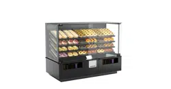
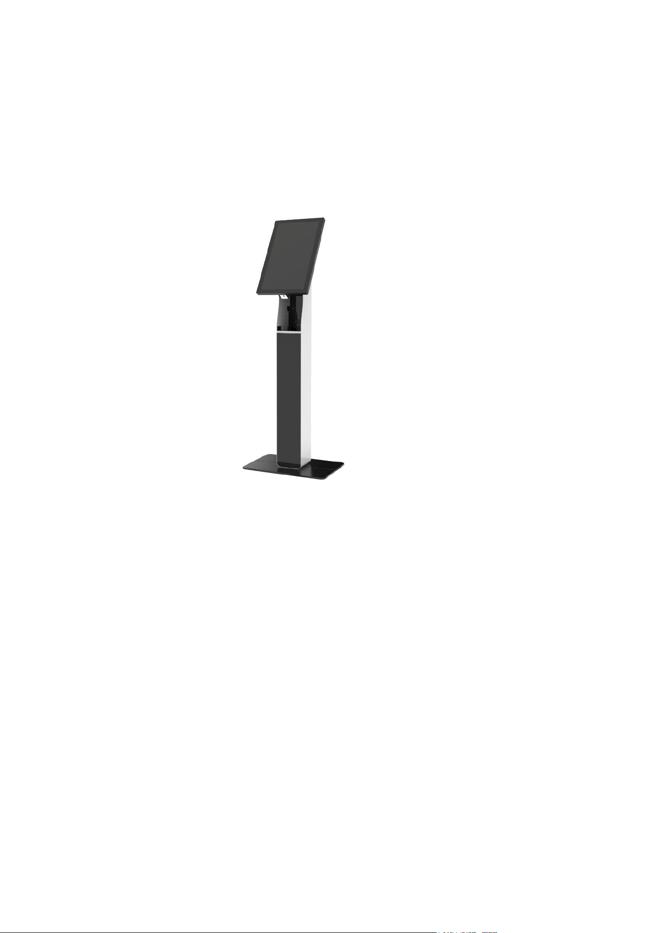
1.1 Overview
Smart Self-Ordering Kiosk, suitable for interactive self-ordering, payment, and other applications.
1.2 Features
VESA mounting holes for various installation options
High resolution FHD(1920x1080)
Optional Windows or Android systems with flexible configurations to meet different customer
requirements
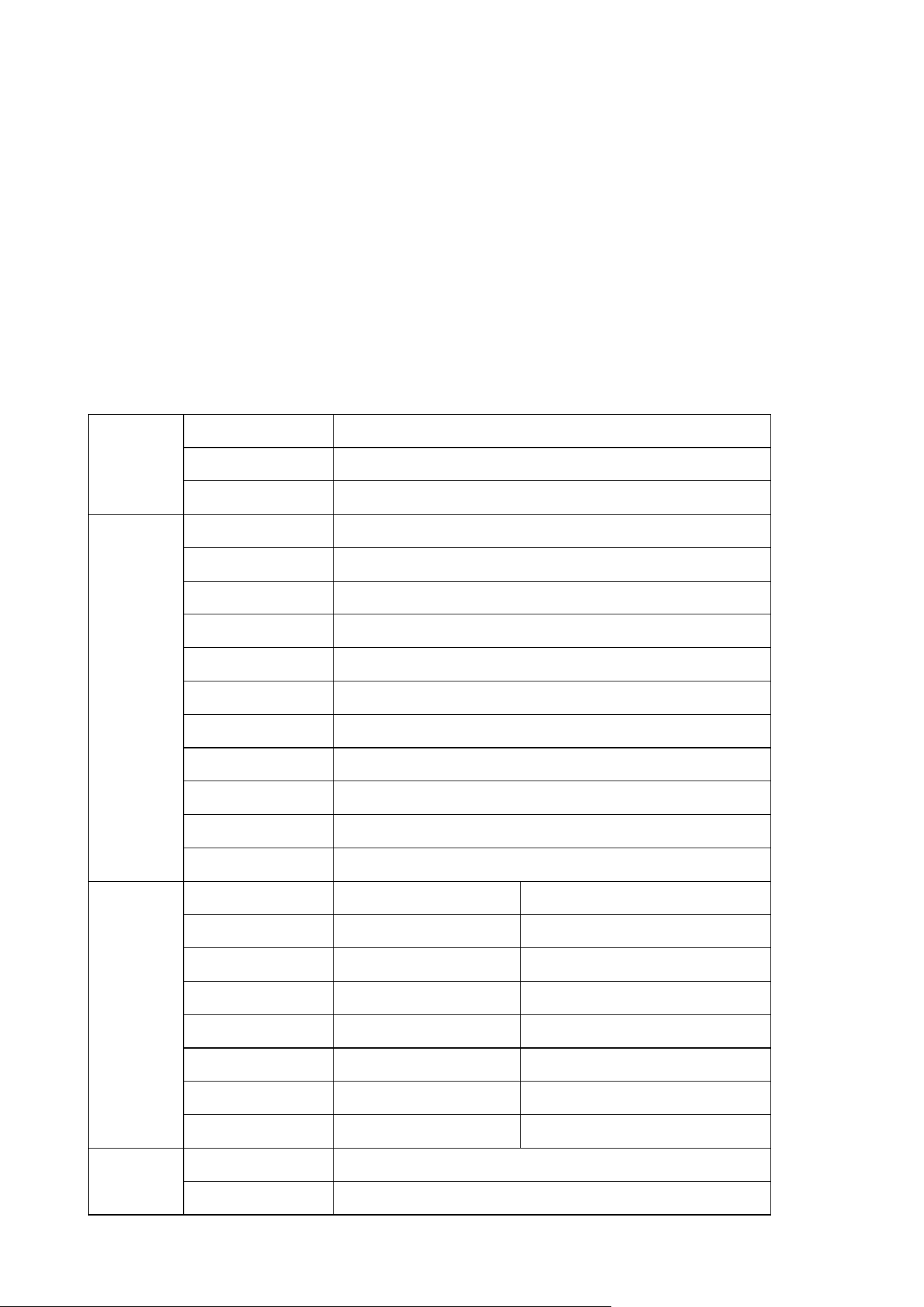
1.3 Specifications
Touch
Screen
Touch Type
Projected Capacitive Touch
Touch Points
10-point
Response Time
10ms
Display
Type
TFT-LCD
Size
21.5 inch
Resolution
1920x1080
Aspect Ratio
16:9
Brightness
500cd/m2
Contrast Ratio
1000:1
Response Time
14ms
Viewing Angle
H178º V178º
Display Colors
16.7M
Refresh Rate
60Hz
Lifetime
30,000 hours
host
OS
WIN10(trial version)
Android 11
CPU
Intel Celeron J6412
Rockchip RK3568
RAM
4G/8G
2G/4G
Storage
128G/256G(SSD)
16G/32G/64G
Speaker
5W*2
5W*2
I/O Ports
USB*4/RJ45*1
USB*2/RJ45*1
Scanner
HF521
HF521
Network
Ethernet /WIFI
Ethernet /WIFI
Power
Voltage
100-240VAC,50/60HZ
Power Consumption
60W
Enclosure
Material
SPCC
Surface Finish
Powder coated
Color
Black (customized)
Dimensions
Overall size
649.4mm*387.4mm*56mm
Net Weight
8.5kg
Package
729mm*144mm*536mm
Gross Weight
11.5kg
Environment
Application
Indoor
Operating Temp.
0~40℃
Storage Temp.
-20~60℃
Operating Humidity
20%~80%
Storage Humidity
10%~90%
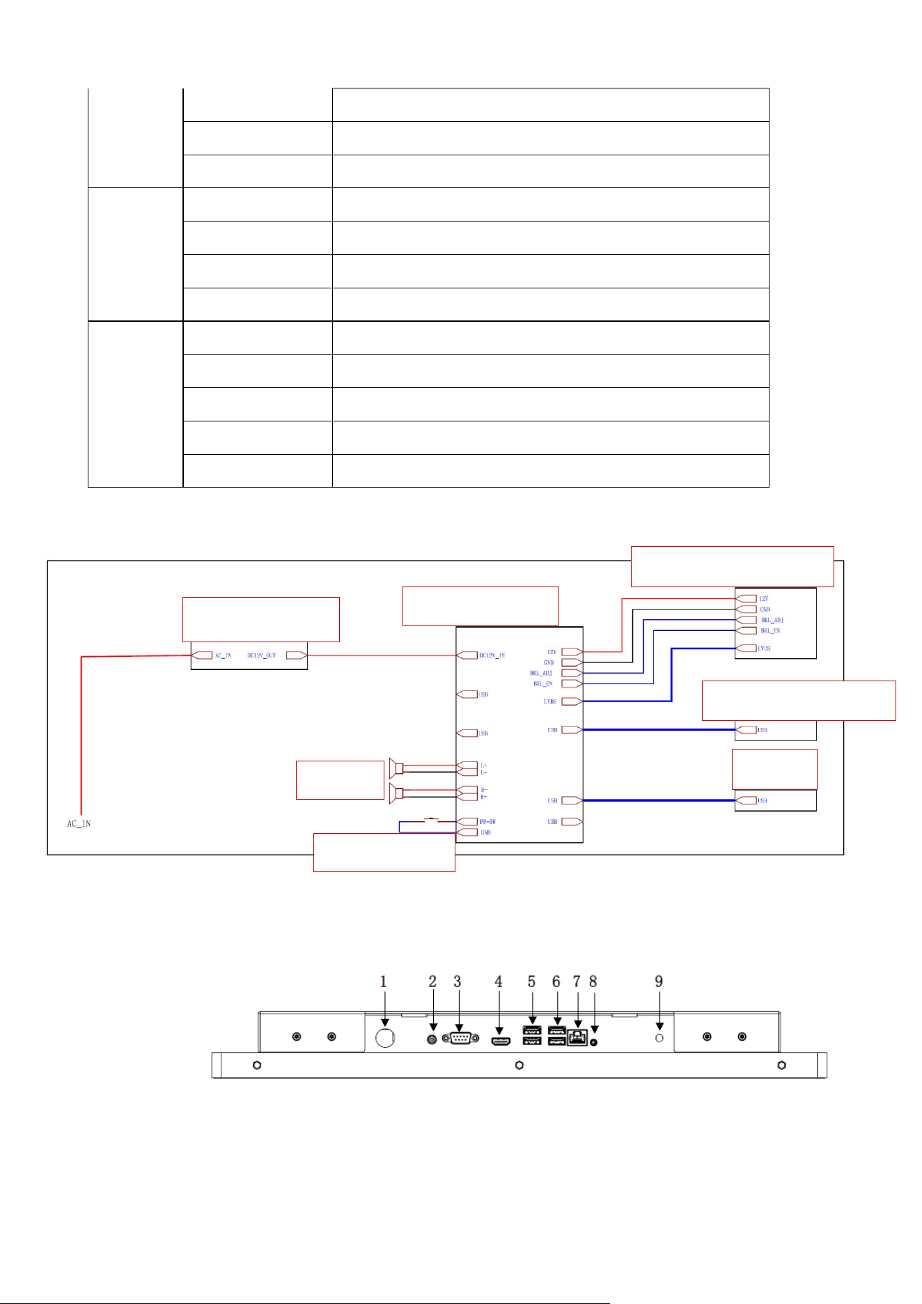
1.4 System Block Diagram
The block diagram below shows the various electronic systems.
1.5 Interface Description
1.5.1Product Interface
Interface layouts may vary depending on the mainboard version (Windows vs. Android, or different
configurations).
1.Windows 6412
Power Adapter
PC Mainboard
21.5-inch Touch Screen
21.5-inch LCD Panel
Speaker
Scanner
Metal Button
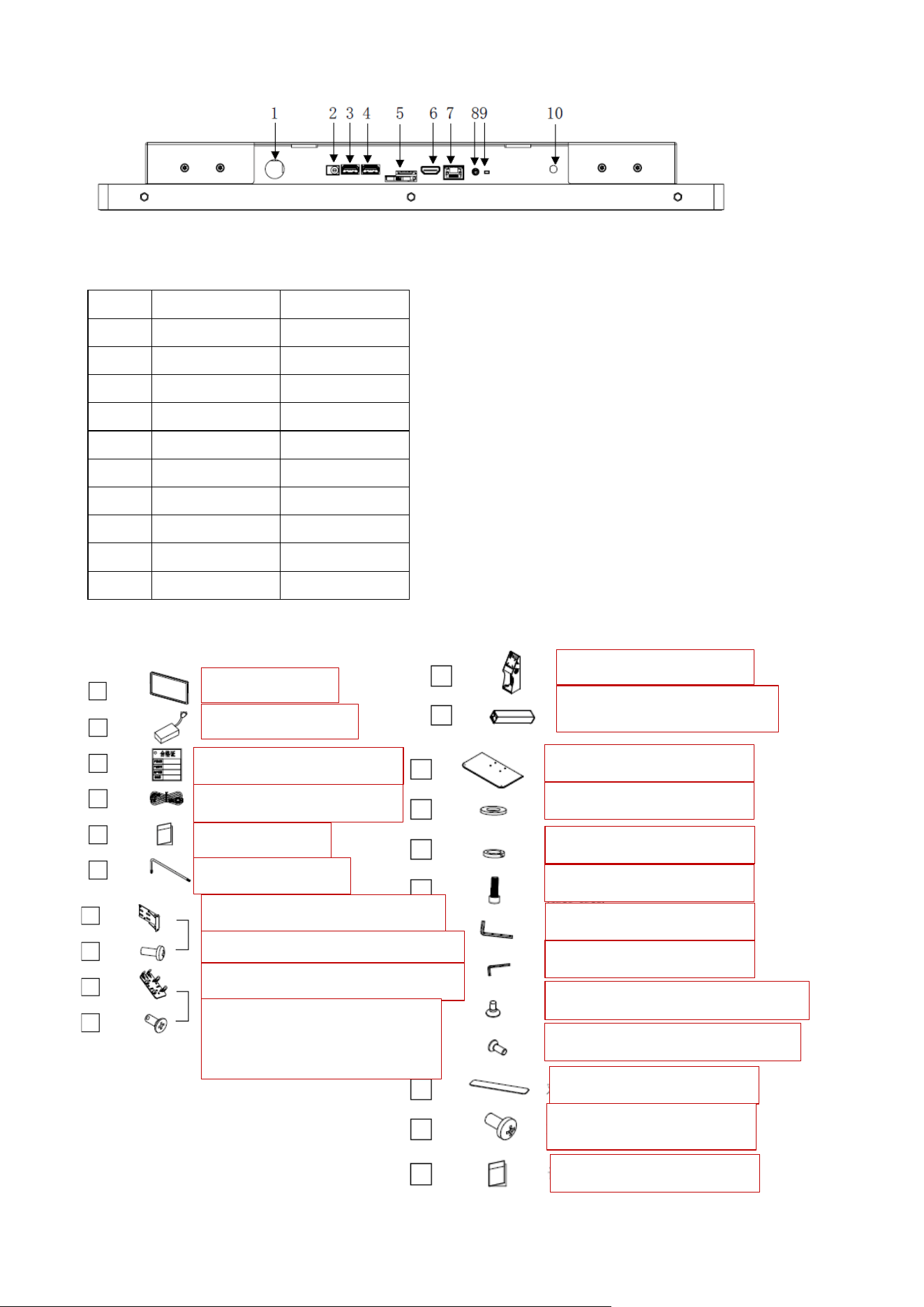
2.Android 3568
1.5.2 Interface Details
No.
Windows
Android
1
Power On
Power On
2
DC IN
DC IN
3
COM
USB
4
HDMI OUT
USB
5
USB*2
TF card
6
USB*2
HDMI IN
7
RJ45
RJ45
8
SPK
SPK
9
Antenna
Reset
10
Antenna
1.6 Accessory Kit Overview
Product
Power Adapter
Certificate of Conformity
Power Cord
User Manual
M3 Torx Wrench
Card Reader Kit (Optional 1)
M4*8 Phillips Pan Head-Optional
Screw
A upper column
A lower column
Large Base
M6 Flat Washer
Card Reader Kit (Optional 2)
Screw
M4*8 Phillips Countersunk
Head-Optional Screw-
Optional Screw
M6 Spring Washer
M6 Cheese Head Screw
S5 L-shaped Wrench
S4 L-shaped Wrench
ST2.9*9.5 Self-Tapping Screw
M6 Countersunk Head Screw
Double-Sided Tape
M4*8 Phillips Screw
User Manual
Chapter 2
Product Installation
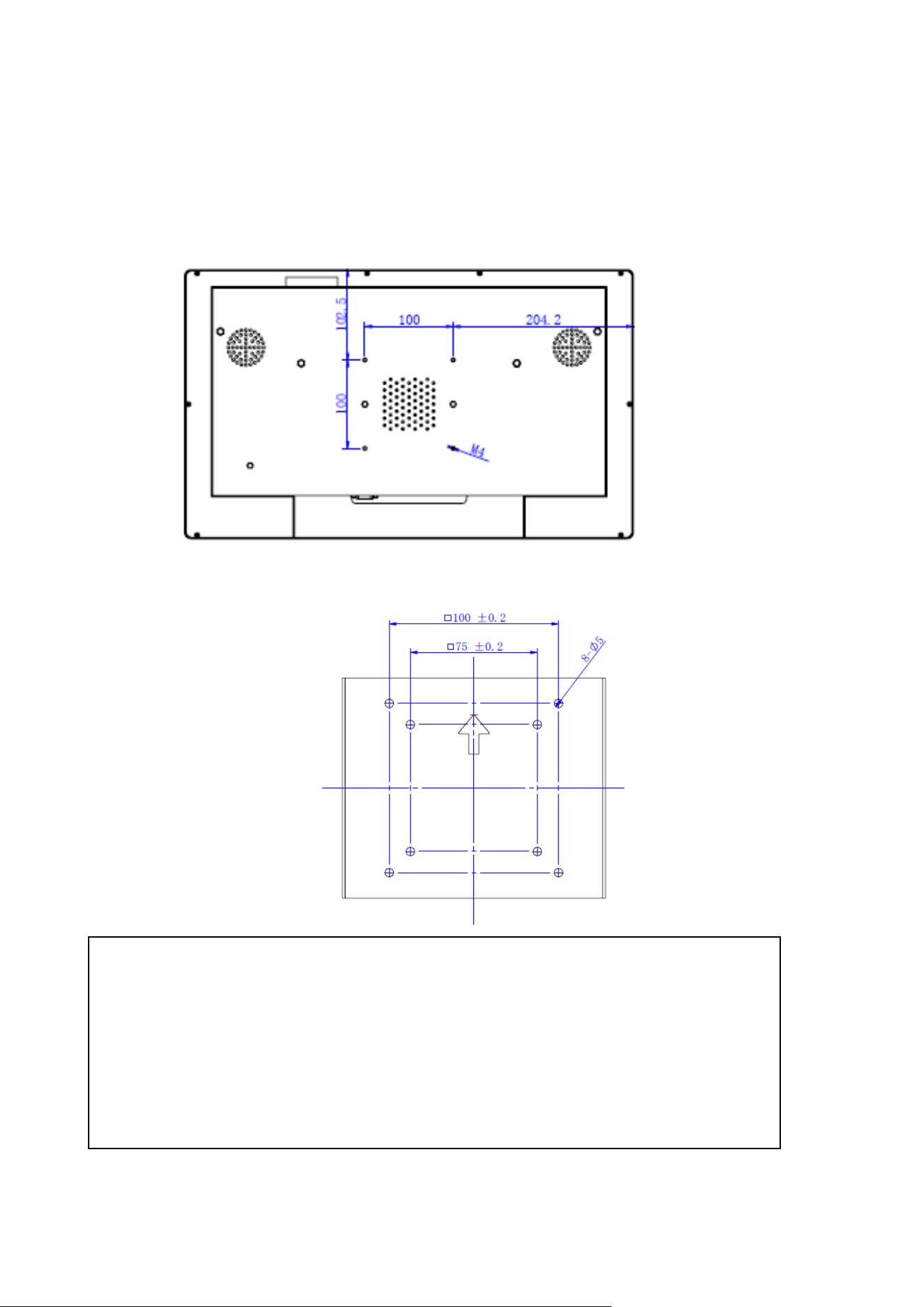
2.1 VESA Mounting
This product complies with the VESA Flat Display Mounting Interface Standard. The VESA mount is
located on the rear of the device and corresponds to the bracket’s mounting plate.
Mounting Holes on the Back of the Touch All-in-One
2.1.1Display Installation
Note: Install or remove the product only when it is powered off.
Warning!
The distance between the rear cover surface and the bottom of the screw hole is 12–14
mm.Use M4 screws of appropriate length to mount the display.
IMPORTANT: The mounting bracket must be capable of supporting at least 10 kg (15 kg
recommended).
注意:安装支架必须能够支持至少 33 磅(15.0 公斤)
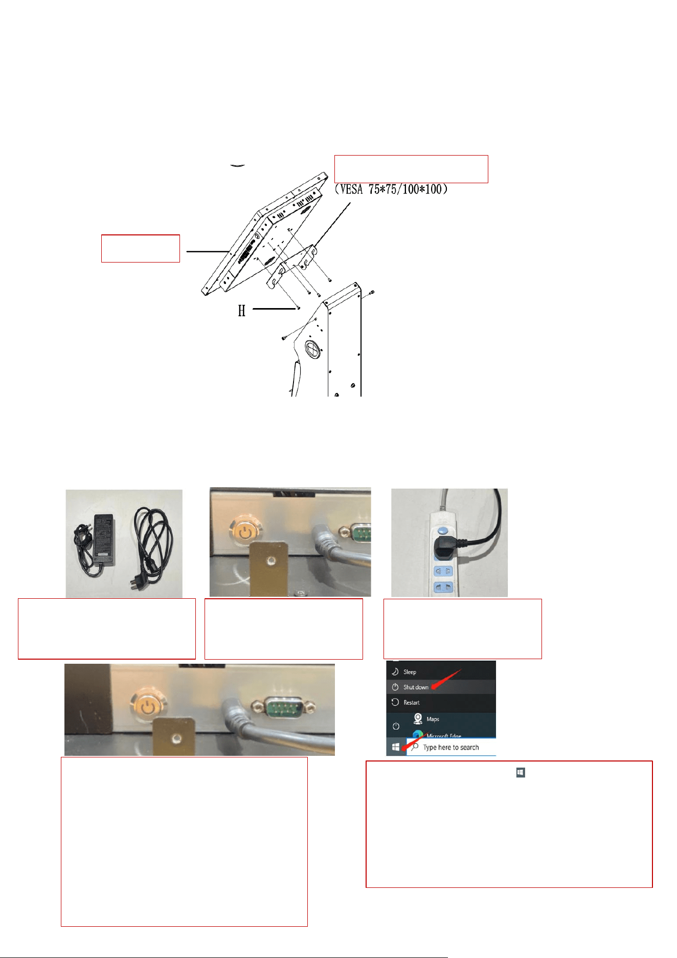
Step 1: Attach the mounting plate to the corresponding holes on the rear of the display using four cross-
head screws, matching the orientation shown.
Step 2: Hang the display (with plate attached) onto the bracket’s locking slots.
Step 3: Tighten both sides using the hand screws.
2.3 Operation Instructions
Instructions for power on/off, brightness adjustment, and volume control are provided. For
other operations, follow the same procedures as a standard computer system.
2.3.1 Power On/Off
1、配送电源适配器, 2、适配器 DC 插头 3、适配器电源线再
电源线接入适配器 插入到机器 DC 插口 插入 AC 电源插座处
4、按下主机启动开关,启动后主机会发出一声 5、关机:如图点击 图标
“滴”的声音,表示主机已经通电开机,等待 从系统中把主机电源关闭,待
主机系统启动即可。请保证机器屏幕没有任何 设备关机后即可拔除电源线,
遮挡物,因机器触摸屏是通过非透明物质感应 请勿直接拔掉电源线,突然断
的,如有遮挡物会出现干扰触摸效果。 电。容易造成机器零部件坏。
Mounting plate
Display
1、Power adapter is included.
Connect the power cord to
the adapter.
2、Insert the DC plug of
the adapter into the DC
jack of the unit.
3、Then plug the adapter
power cord into the AC
outlet.
4、Press the power button to start the unit.
After startup, the unit will emit a single
"beep" sound, indicating that the main unit
is powered on. Please wait for the system
to boot up. Ensure that the screen is free of
any obstructions, as the touchscreen
operates based on sensing through non-
transparent objects. Any obstruction may
interfere with touch performance.
5、Shutdown: Click the icon as shown in the
figure to power off the unit from the operating
system. After the device has completely shut down,
the power cord may be unplugged. Do not unplug
the power cord directly, as sudden power loss may
damage internal components.
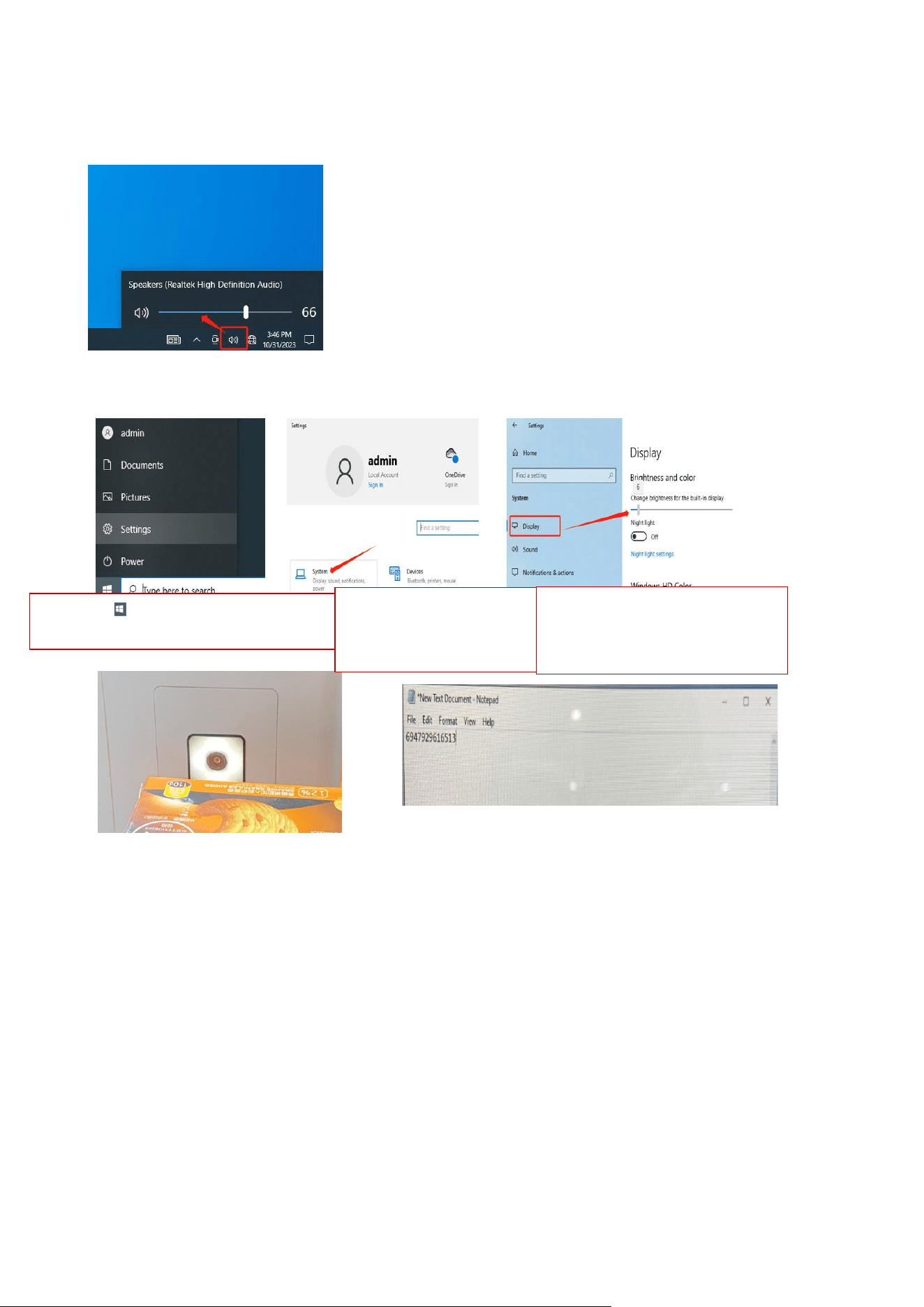
2.3.2 System Volume Adjustment
Click the volume icon in the system tray and adjust to the desired level.
2.3.3 Screen Brightness Adjustment
Navigate through: Menu → Settings → Display → Brightness adjustment.
2.3.3 Scanner Operation
Bring a QR code or barcode close to the scanner window. The LED lights up,and the decoded data
appears on the screen.
Remark:
The following models are covered (touch all-in-one and touch monitor variants):
Touch All-in-One:
DSW-B1156-S4B、DSW-B1215-S4B、DSW-B119-S4A、DSW-B1238-S4B、DSW-B127-S4B、DSW-
B132-S4B、DSW-B143-S4B、DSW-B155-S4B
Touch Monitor:
TS-B1156-S4B、TS-B1215-S4B、TS-B119-S4A、TS-B1238-S4B、TS-B127-S4B、TS-B132-S4B、
TS-B143-S4B、TS-B155-S4B
1、 Click icon to enter the menu
settings page.
2、 Click to enter the
system settings page.
3、 Select Display Settings,
then adjust the brightness.

FCC Warnning:
This equipment has been tested and found to comply with the limits for a Class B digital device,
pursuant to part 15 of the FCC Rules. These limits are designed to provide
reasonable
protection againstharmful interference in a residential installation. This equipment generates,
uses and can radiateradio
frequency
energy
and,
if
not
installed
and
used
in
accordance
with
the
instructions,
maycause
harmful
interference
to
radio
communications.
However,
there
is
no
guarantee
thatinterference
will
not
occur
in
a
particular
installation.
If
this
equipment
does
cause
harmfulinterference to radio or television reception, which can be
determined by turning the equipmentoff
and
on,
the
user
is
encouraged
to
try
to
correct
the
interference
by
one
or
more
of
thefollowing measures:
•
Reorient or relocate the receiving antenna.
•
Increase the separation between the equipment and receiver.
•
Connect the equipment into an outlet on a circuit different from that to which the receiver is
connected.
• Consult the dealer or an experienced radio/TV technician for help.
Caution:
Any
changes
or
modifications
to
this
device
not
explicitly
approved
by
manufacturer
could void your authority to operate this equipment.
This
device
complies
with
part
15
of
the
FCC
Rules.
Operation
is
subject
to
the
following
two
conditions:
(1)This
device
may
not
cause
harmful
interference,
and
(2)
this
device
must
accept
any
interference received, including interference that may cause undesired operation.
This
equipment
complies
with
FCC
radiation
exposure
limits
set
forth
for
an
uncontrolled
environment.
This
equipment
should
be
installed
and
operated
with
minimum
distance
20cm
between the radiator and your body.