USER MANUALS\21-30330_FUSION_USER MANUAL_GHSS476H-8110_HTD_SELF-SVC CASE REV B DATE: 05/30/2023
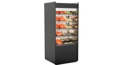
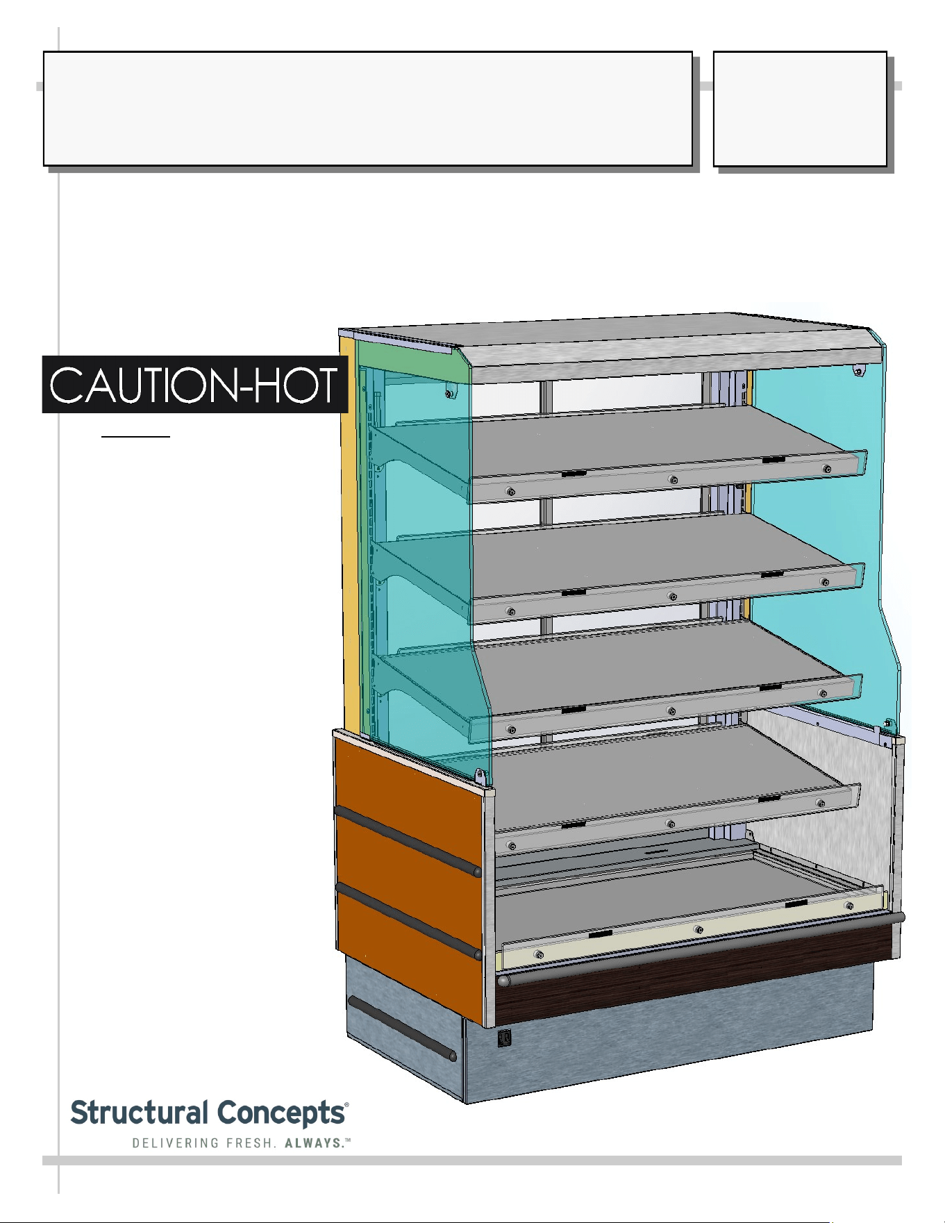
SELF-SERVICE MERCHANDISER WITH HEATED SHELVES AND DECK
> THERMOSTATS (CONTROLLING HEAT TO SHELVES/DECK)
> HEATER FANS (NEAR UPPER PLENUM)
> REAR SLIDING REFLECTIVE GLASS DOORS (STANDARD)
> REAR STAINLESS SOLID BACK (OPTIONAL)
> SOLID METAL SHELVING
> GLASS END PANELS
Important! See Installation
Section of Manual to
Confirm Proper Placement of
“Caution-Hot” Labels on
Polycarbonate Heat Shields
on Heated Shelves and Deck
Model GHSS476H.8110
Structural Concepts Corp. ∙ 888 E. Porter Rd ∙ Muskegon, MI 49441 Phone: 231.798.8888 Fax: 231.798.4960 ∙ www.structuralconcepts.com
FUSION
User
Manual
READ AND SAVE THESE INSTRUCTIONS
SCC P/N
21-30330
2
TABLE OF CONTENTS
OVERVIEW / TYPE / COMPLIANCE / WARNINGS / PRECAUTIONS / WIRING / PLUGS ...........…..
INSTALLATION: TOE-KICK REMOVAL FROM CASE / CASE REMOVAL FROM SKID …………….
INSTALLATION: POSITIONING & ALIGNING CASE / BASE FRAME SHIMMING …….……………..
INSTALLATION, CONT’D: ATTACHING & SEALING SPLASH GUARD BRACKET TO REAR
BASE FRAME …………………………………………………………………………………………..
INSTALLATION, CONT’D: INNER CLOSE-OFFS / SIDE TOE-KICKS / SEALING CLOSE-OFFS TO
FLOOR / REPLACING FRONT & REAR TOE-KICKS ……………………………………………….
INSTALLATION, CONT’D: IMPORTANT! HEATED SHELF LABEL PLACEMENT ……………….….
INSTALLATION, CONT’D: ELECTRICAL-FIELD WIRING BOX / FRONT TOE-KICK ………….....….
STARTUP: ELECTRICAL BOX / MAIN POWER SWITCH / LED LIGHTS / THERMOSTATS /
THERMOMETER ….…………………………………………………………………………………...
STARTUP, CONT’D: HEATER FANS ………………………………………………………………………..
STARTUP, CONT’D: START-UP, OPERATION AND SHUTDOWN (AUTHORIZED PERSONNEL
ONLY!) .......................................................................................................................................
GENERAL LAYOUT: CASE FRONT …………………………………………………………………………...
GENERAL LAYOUT, CONT’D: CASE REAR ….……………………………………………………………...
GENERAL LAYOUT, CONT’D: LED LIGHTS / LED REMOVAL & REPLACEMENT ……..……………..
GENERAL LAYOUT, CONT’D: POWER CORD & PLUG, LED LIGHTS AND LIGHT FIXTURES ……..
CLEANING SCHEDULE: CASE EXTERIOR - DAILY, WEEKLY AND MONTHLY …….……………...
CLEANING SCHEDULE, CONT’D: CASE INTERIOR - DAILY ………………………….….…….……...
TROUBLESHOOTING ….…………………………………………………..………………...………………..
SERIAL LABEL & LOCATION / TECHNICAL INFORMATION / ADDITIONAL INFORMATION .…...
PROGRAMMABLE CONTROLLER INFORMATION ………………………………………......………….
TECHNICAL SERVICE CONTACT INFORMATION / WARRANTY INFORMATION…………………..
3-4
5
6
7
8
9
10
11
12
13
14
15
16
17
18
19
20
21
22
23
3
OVERVIEW
This Fusion merchandiser is designed for dry heating
operations throughout the product area. Heat is generated
from both shelving and deck.
• Cases should be installed and operated according to
this operating manual’s instructions to insure proper
performance.
• These Structural Concepts® self-service heated
merchandisers are designed to hold pre-heated hot
foods at 140 °F to 165 °F (60 °C to 74 °C).
• Product must be pre-heated to these temperatures
PRIOR TO being placed in merchandiser. This case is
NOT designed to heat product from cold or ambient
conditions.
• This merchandiser is designed for display of
perishable, packaged products.
• Improper use will void warranty.
TYPE “1” CONDITION
This unit is designed for the display of products in ambient
store conditions where temperatures and humidity are
maintained within a specific range.
COMPLIANCE
This equipment MUST be installed in compliance with
all applicable NEC, federal, state and local
electrical and plumbing codes.
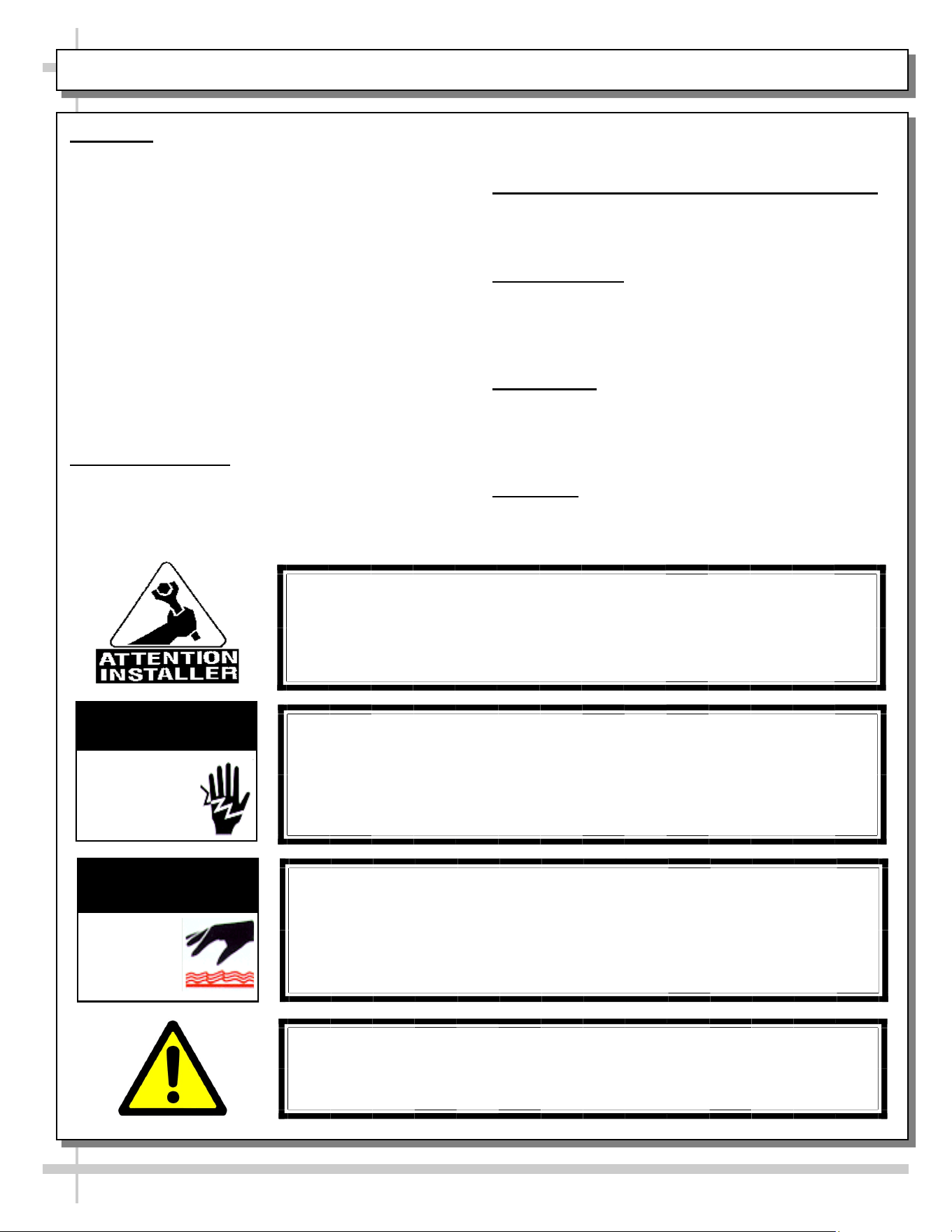
WARNING
Risk of electric shock. Disconnect power before servicing unit.
CAUTION! More than one source of electrical supply is
employed with units that have separate circuits.
Disconnect ALL ELECTRICAL SOURCES before servicing.
WARNING
ELECTRICAL
HAZARD
WARNING
Shelves and Deck Are Hot! Turn Off Main Power Switch and allow to
cool 45 minutes before cleaning or removing from case.
WARNING
HOT
SURFACE
OVERVIEW / TYPE / COMPLIANCE / WARNINGS / PRECAUTIONS / WIRING / PLUGS - PAGE 1 of 2
• Ambient conditions are to be at 55% max. humidity
and maximum temperatures of 75 °F (24 °C).
INTEGRATED AVERAGE PRODUCT TEMPERATURE
• These units are designed to merchandise product at
an integrated average product temperature of
150 °Fahrenheit / 66 °Celsius.
THERMOMETERS
• Thermometers in equipment reflect internal air
temperature only (not actual food temperature).
• Use probe thermometers to determine actual product
temperatures.
COMPLIANCE
• Performance issues when in violation of applicable
NEC, federal, state and local electrical and plumbing
codes are not covered by warranty.
• See below compliance guideline.
WARNINGS
• This page contains important warnings to prevent
injury or death. Please read carefully!
WARNING: This product can expose you to chemicals, including
Urethane (Ethyl Carbamate), which are known to the state of
California to cause cancer and birth defects or other reproductive
harm. For more information go to P65Warnings.ca.gov.
4
PRECAUTIONS
• Following are important precautions to prevent damage to unit, merchandise or product.
• Please read carefully!
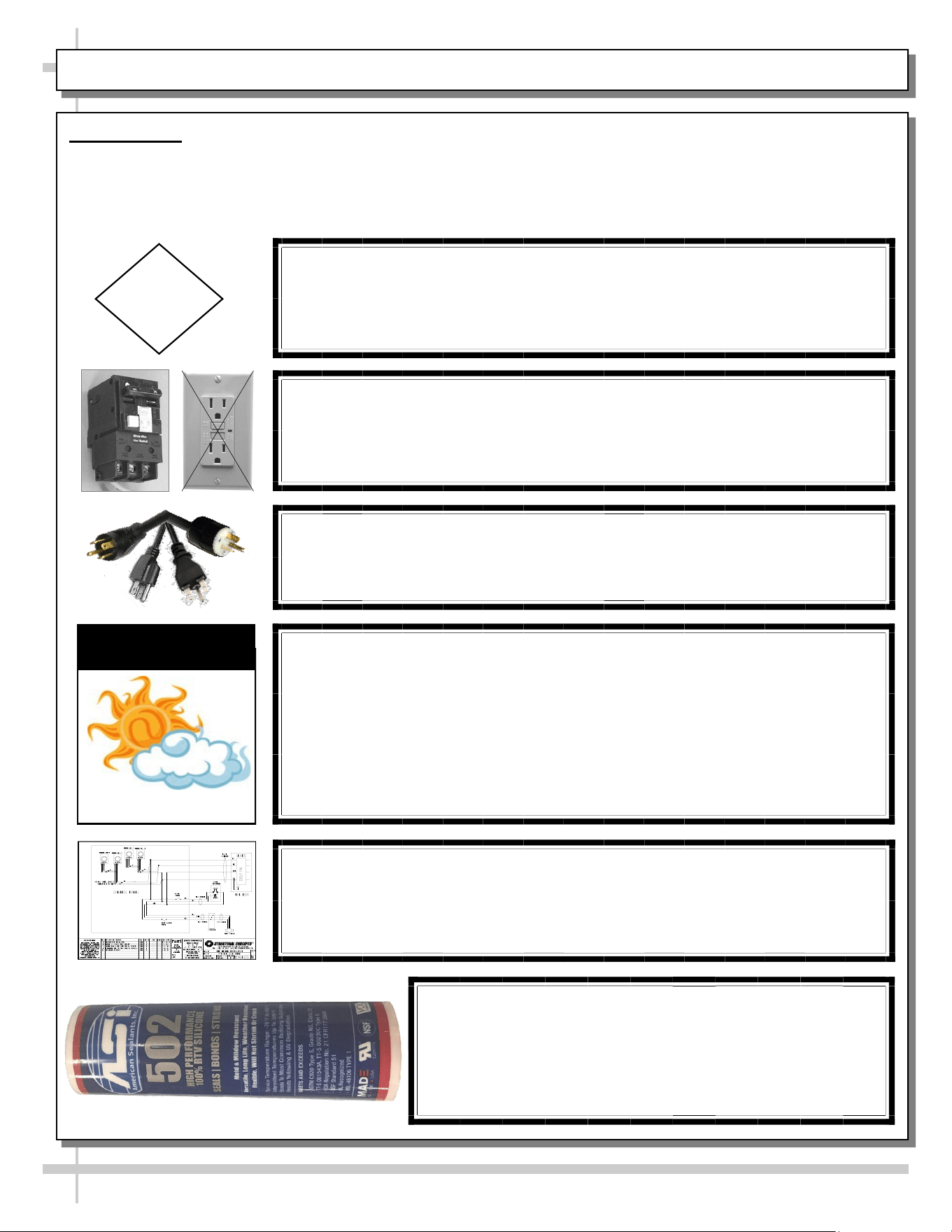
CAUTION! LAMP REPLACEMENT GUIDELINES
LED lamp replacements must meet factory specifications.
CAUTION
CAUTION! ADVERSE CONDITIONS / SPACING ISSUES
• Performance issues caused by adverse conditions are NOT warranted.
• When adjoining to another heated case (without end panels), apply
industrial grade silicone sealant along uprights and lower base. Tightly
join to opposite end panels.
• Case must not be exposed to direct sunlight or any heat source.
• To maintain proper case temperature, keep case at least 15-feet from
exterior doors, overhead HVAC vents or any air curtain disruption.
CAUTION
CAUTION! POWER CORD AND PLUG MAINTENANCE
Risk of electric shock. If cord or plug becomes damaged,
replace only with cord and plug of same type.
OVERVIEW / TYPE / COMPLIANCE / WARNINGS / PRECAUTIONS / WIRING / PLUGS - PAGE 2 of 2
CAUTION! GFCI BREAKER USE REQUIREMENT
If N.E.C. (National Electric Code) or your local code
requires GFCI (Ground Fault Circuit Interrupter) protection,
you MUST use a GFCI breaker in lieu of a GFCI receptacle.
WIRING DIAGRAM FORMAT & LOCATION
• Each case has its own wiring diagram folded & in its own packet.
• Wiring diagram placement may vary; it may be placed near ballast
box, field wiring box, raceway cover, or other related location.
SEAL FLOOR-MOUNTED UNITS TO THE FLOOR
• Thoroughly clean floor to assure a secure seal.
• Base frames or fixed (non-removable) cladding,
panels, adjustable close-offs and/or splash guard
brackets must be sealed to floor with silicone that
meets or exceeds food grade NSF/ANSI Standard 51.
5
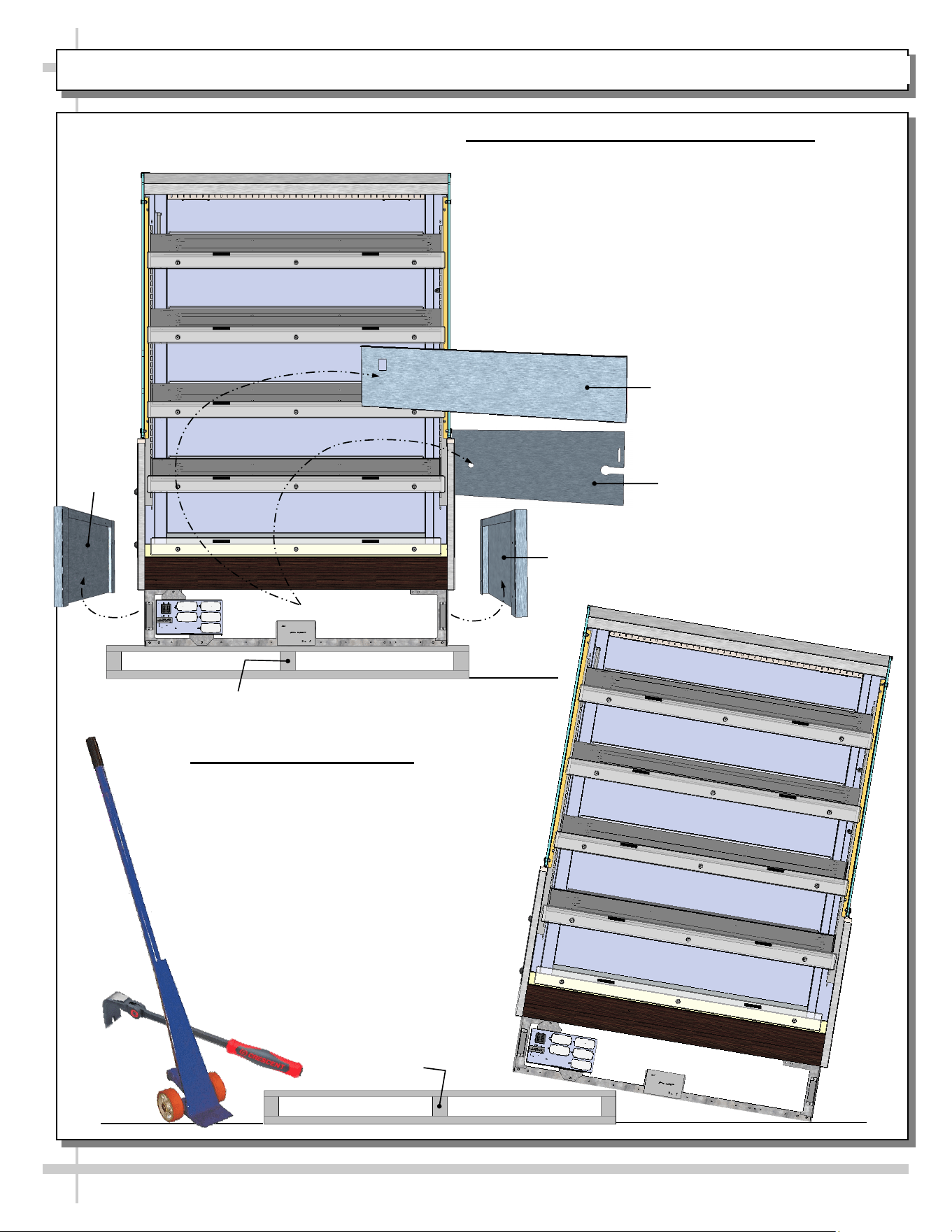
INSTALLATION: TOE-KICK REMOVAL FROM CASE / CASE REMOVAL FROM SKID
1. Remove Front, Rear and Side Toe-Kicks
Important! To prevent damage to case, you must
remove front, rear and side toe-kicks.
• Front toe-kick is held in place by magnets.
• Rear toe-kick is held in place by screws.
• Left/Right side toe-kicks are held in place by screws.
• Adjustable close-offs (as illustrated on page 8 of
User Manual) are taped to inner lower end panels.
• See illustration at left.
Skid
Front Toe-Kick
Rear Toe-Kick
2. Remove Case From Skid
• Caution! Case must always remain
supported or center of gravity will
allow case to fall.
• Use J-bar or indexing flat pry bar as
needed for leverage.
• Slide unit to end of skid and slowly
lower it onto floor.
• Slide skid out from under case while
case is being supported.
• See illustration at right.
J-Bar
Indexing Flat Pry Bar
Skid
Right Side Toe-Kick
Right
Side
Toe-Kick
3. Positioning & Aligning Case Alongside Others
• Before shimming base frames, make
certain case is in proper position and, if
required, aligned with adjoining case.
• This may require the repositioning of the case
you are installing or the already positioned case.
6
INSTALLATION: POSITIONING & ALIGNING CASE / BASE FRAME SHIMMING
Base Frames
4. Shim Base Frames
• Shims will be provided for leveling case.
• Shims are to be placed at underside of base
frames.
• Use indexing flat pry bar as needed for leverage.
• Front and rear toe-kicks should remain off case
while shimming base frames.
Indexing Flat
Pry Bar
7
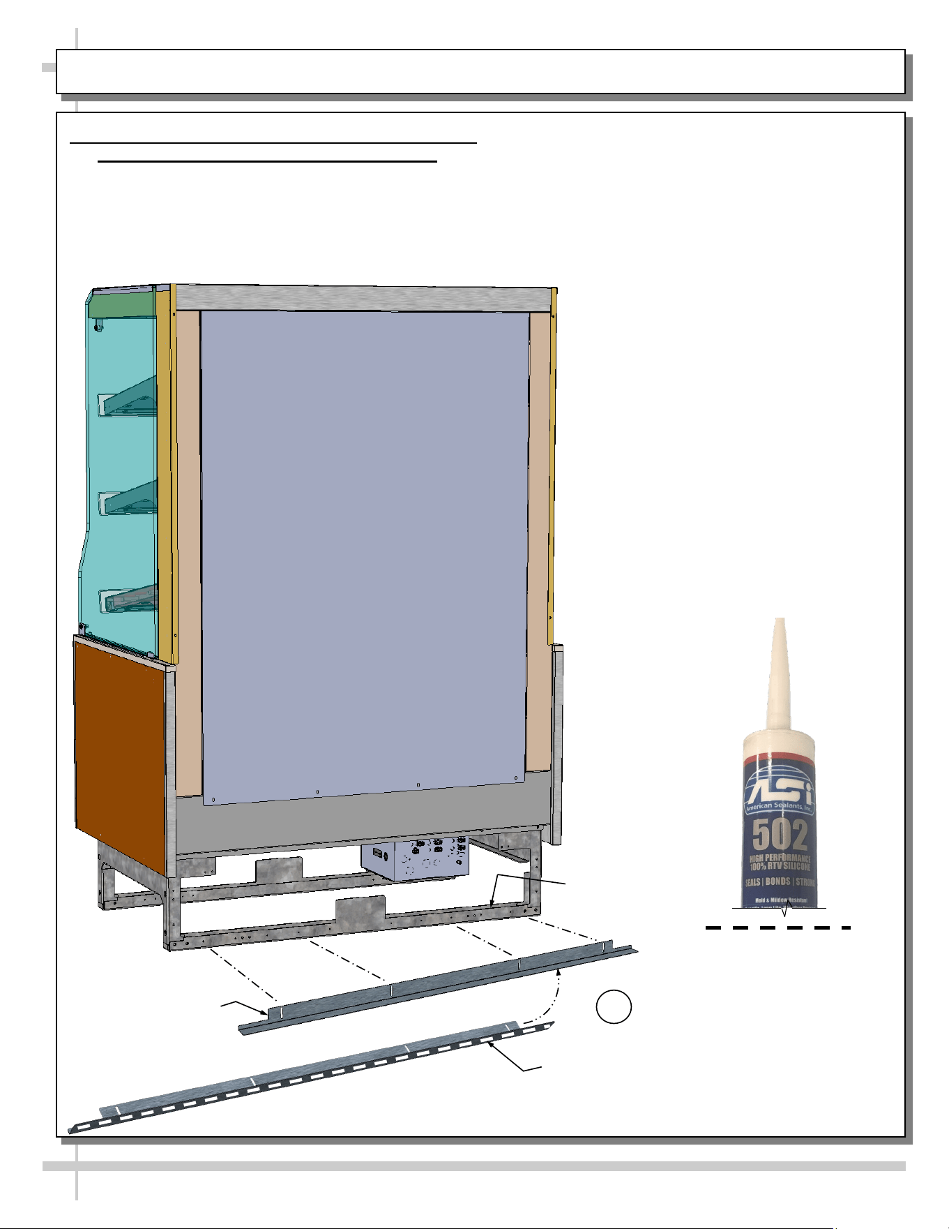
INSTALLATION, CONT’D: ATTACHING/SEALING SPLASH GUARD BRACKET TO REAR BASE FRAME
• After case has been properly positioned and
base frames have been shimmed, place a bead
of silicone sealant to underside of splash guard
bracket (that will rest on floor).
• Center the back of the bracket flush against
frame support rail; attach to frame support rail
with SCC-supplied screws.
• See illustrations below.
Splash Guard
Bracket Shown
Removed
From Case
Rear Base
Frame
5. Applying Sealant To Underside of Splash Guard
Bracket / Attaching It To Rear Base Frame
• Splash guard bracket prevents entry or leakage of
liquid or moisture to underside of case.
• Splash guard bracket will likely be attached to
skid during shipment.
Splash Guard Bracket Shown With
Silicone Sealant Applied At Underside
5
Silicone Sealant (To Match
Case Color) Conforming To
NSF/ANSI 51 Specs (For
Outer Bead Applications)
8
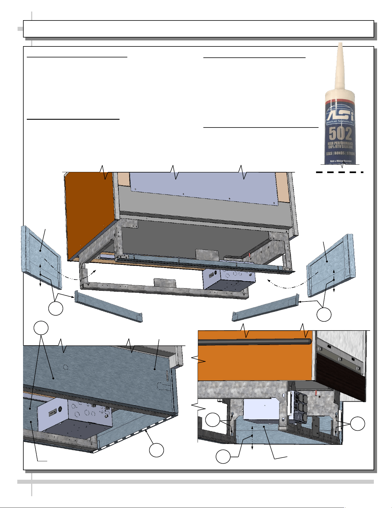
INSTALLATION, CONT’D: INNER CLOSE-OFFS / SIDE TOE-KICKS / SEALING CLOSE-OFFS TO FLOOR
6. Inner Adjustable Close-Offs
• Inner adjustable close-offs are gravity-based
(without screws to hold them intact).
• Inner adjustable close-offs are taped at the inside
of side toe-kicks during shipment.
• Remove tape from close-offs, allowing them to
freely float up and down (as shown).
7. Attaching Side Toe-Kicks
• Side toe-kicks are attached to base frame with
four (4) supplied screws at each end (as shown).
• Inner adjustable close offs MUST BE inserted in
side toe-kicks before attachment to base frame.
Side
Toe-Kick
Side
Toe-Kick
8
9
6
6
7
6
7
Side Toe-Kick (Typ.)
Silicone Sealant (To
Match Case Color)
Conforming To
NSF/ANSI 51 Specs (For
Outer Bead Applications)
8. Silicone Sealant Application
• Apply silicone sealant to floor directly
underside of gravity-based
adjustable close-offs.
• Lower close-offs and seal them to
the floor.
• Case shown suspended
for illustration purposes only.
9. Replace Front & Rear Toe-Kicks
• Replace front toe-kick (via
magnets) and rear toe-kicks (via
screws).
• See illustrated below.
Rear Toe-Kick
Front Toe-Kick
9
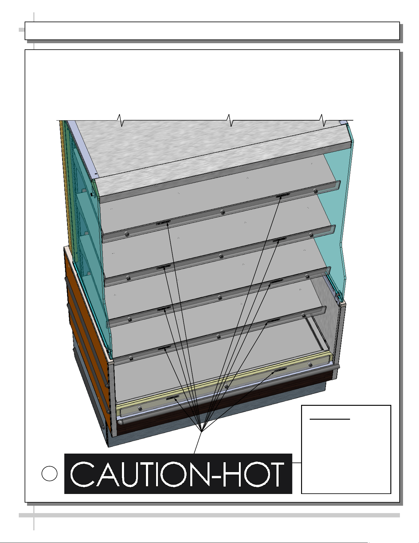
INSTALLATION, CONT’D: IMPORTANT! HEATED SHELF LABEL PLACEMENT
Important! Check
That “Caution-Hot”
Labels Are Properly
Placed On The
Polycarbonate Heat
Shields (on Heated
Shelves and Deck)
as Shown.
10. Important! Check That “Caution-Hot” Labels Are Properly Attached To Case.
• Shelves and deck can get extremely hot and cause severe burns.
• Illustration below shows proper placement of “Caution-Hot” labels.
• Two labels must be placed on each shelf and deck (as shown below).
• If labels are NOT properly attached, contact Structural Concepts. See SCC TECHNICAL SERVICE
CONTACT INFORMATION section in this manual for contact information.
10
10
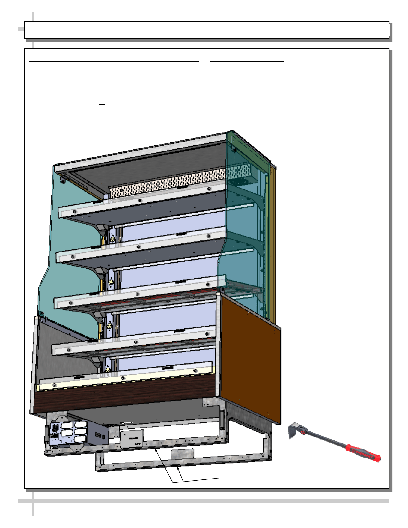
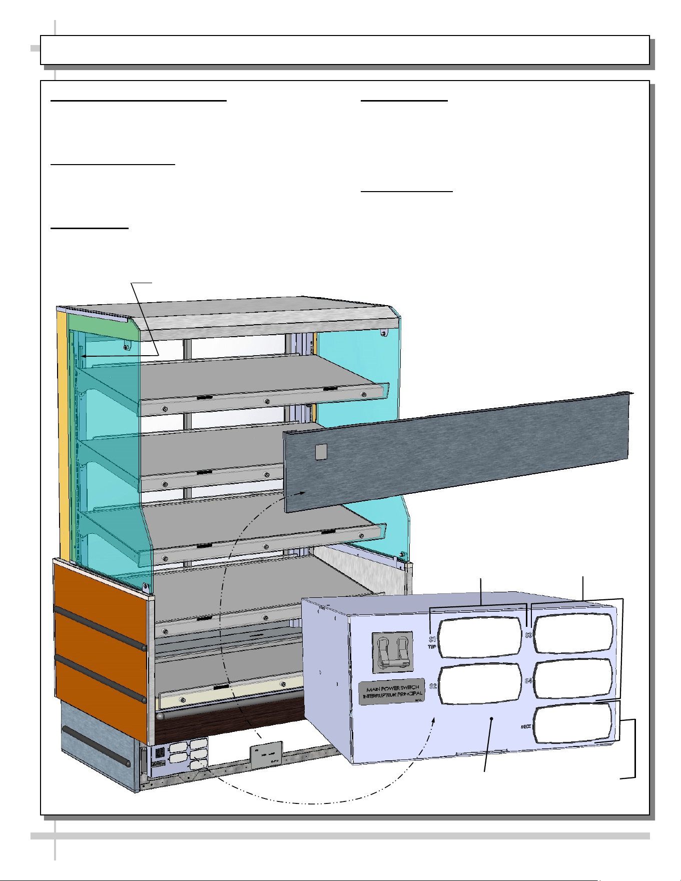
INSTALLATION, CONT’D: ELECTRICAL-FIELD WIRING BOX / FRONT TOE-KICK
11. Electrical Box/Field Wiring Box
• Electrical/field wiring box is accessible at front
of case (after removal of front toe-kick).
• Electrical box contains main power switch and
thermostats to all shelves and deck.
Main Power
Switch
12
Magnet
12. Removable Toe-Kick (Magnetized)
• Front toe-kick is usually shipped separately.
• Front toe-kick is removable by grasping upper lip
and pulling forward (to release from magnets).
• See illustration below.
Magnet
11
4. Thermostats
• Thermostats are in electrical box at case front.
• Thermostats control heat to deck and four (4)
shelves.
• See next page for thermostat controller
specifics.
5. Thermometer
• Thermometer is located at upper left of upright.
• Thermometer reflects internal air temperature
only (not actual food temperature).
• Use probe thermometer to determine ACTUAL
product temperatures.
11
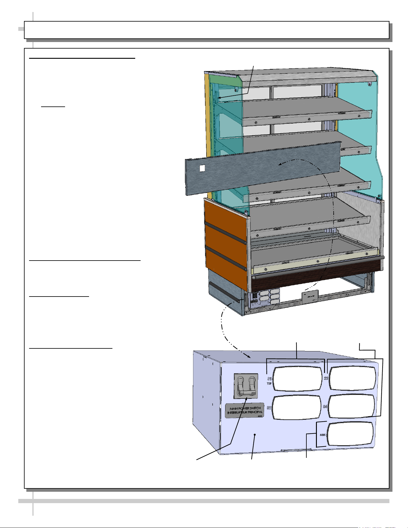
STARTUP: ELECTRICAL BOX / MAIN POWER SWITCH / LED LIGHTS / THERMOSTATS / THERMOMETER
1. Electrical / Field Wiring Box
• Electrical box contains main power switch and
thermostats.
• It is accessible by removing front panel.
2. Main Power Switch
• Main power switch is in electrical box at case front.
• Main power switch controls power to lights AND
thermostats.
3. LED Lights
• Case’s LED lights will come on when Main Power
Switch is turned on.
Thermometer
Thermostats For
Shelves 1 & 2
Thermostats
For Shelves
3 & 4
Front Toe-Kick
Thermostat
For Deck
Electrical / Field
Wiring Box
12
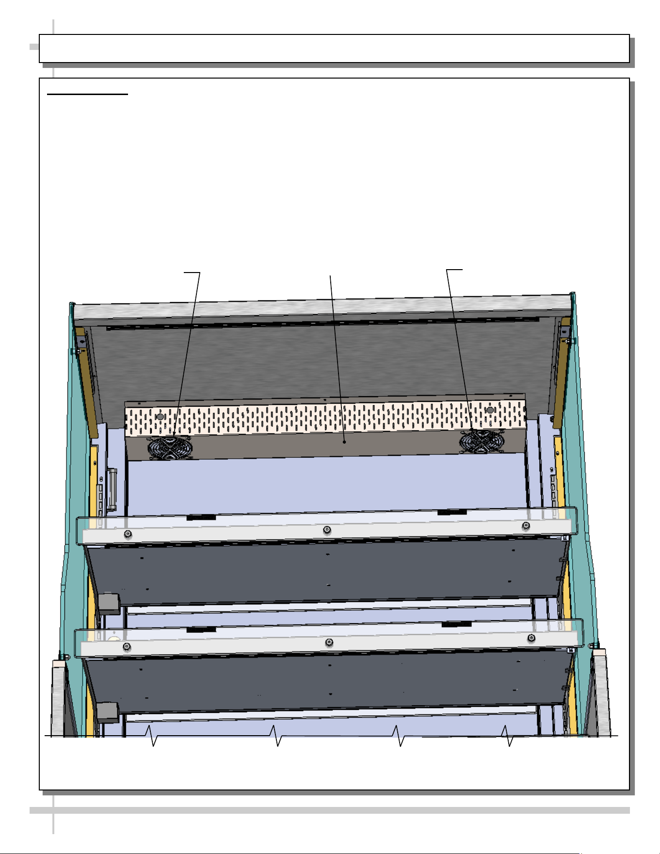
STARTUP, CONT’D: HEATER FANS
6. Heater Fans
• Heater fans operate WITHOUT a separate on/
off switch.
• Heater fans draw warm air from top of case and
distributes it to entire case.
• When unit is energized, check that heater fans are
operational.
• If either heater fan is inoperable, check
TROUBLESHOOTING section in this User Manual.
• See illustration below for general location of heater
fans.
Heater Fan
Heater Fan
Heater Fan Assembly Bracket
--- Angled View of Model GHSS476H.8110 (To View Heater Fan Assembly Bracket) ---
13
STARTUP, CONT’D: START-UP, OPERATION AND SHUTDOWN (AUTHORIZED PERSONNEL ONLY!)
7. Merchandiser Daily Start-Up
• Turn Main Power Switch “ON” (by flipping switch
up).
• LED lights will immediately come on.
• Thermostats (for all shelves and deck) are pre-set
at factory to recommended settings.
• Caution! Food MUST BE cooked PRIOR to being
placed in the case. Food should be heated to a
temperature of between 150 °F to 160 °F (65.6 °C
to 71 °C) prior to placing in case. Food
temperature must NOT be allowed to be below
FDA guideline of 140 °F (60 °C).
• Use probe to check food temperature before
placing in the case.
• After product is placed in case, check
product temperature (again) after one hour
to verify that proper food temperatures are
maintained.
• Due to thermostats being pre-set at factory,
adjustments to thermostats should be very
rare. However, should product temperatures be
outside of range, see programmable controller
section in manual for specifics on adjusting
thermostats.
• After thermostat has been adjusted, check food
temperatures again after one hour with probe.
8. Temperature Control Settings
• Temperatures of all food products are to be at
140 °F to 165 °F (60 °C to 74 °C), for decks and
shelves (including optional shelf #4).
9. Operating Tips
• When restocking, place new product at rear and
rotate older product to front of case.
• Display product expected to sell within 4 hrs.
• Clean up residue immediately. Case will cause
spills and debris to harden to surface!
10. Shutting Down Case
• Turn Main Power switch “OFF” (by flipping
switch down).
• Remove all product from the case (and place in
refrigerated units).
• Caution! Deck and shelving is hot! Do not
touch until case has been turned off allowed to
cool for 45 minutes!
• Allow case to cool for 45 minutes before
cleaning.
• See CLEANING SCHEDULE (DAILY /
WEEKLY) - CASE INTERIOR for specifics.
Thermometer
Thermostats For
Shelves 1 & 2
Thermostats
For Shelves
3 & 4
Thermostat
For Deck
Front Toe-Kick
Electrical / Field
Wiring Box
Main Power
Switch
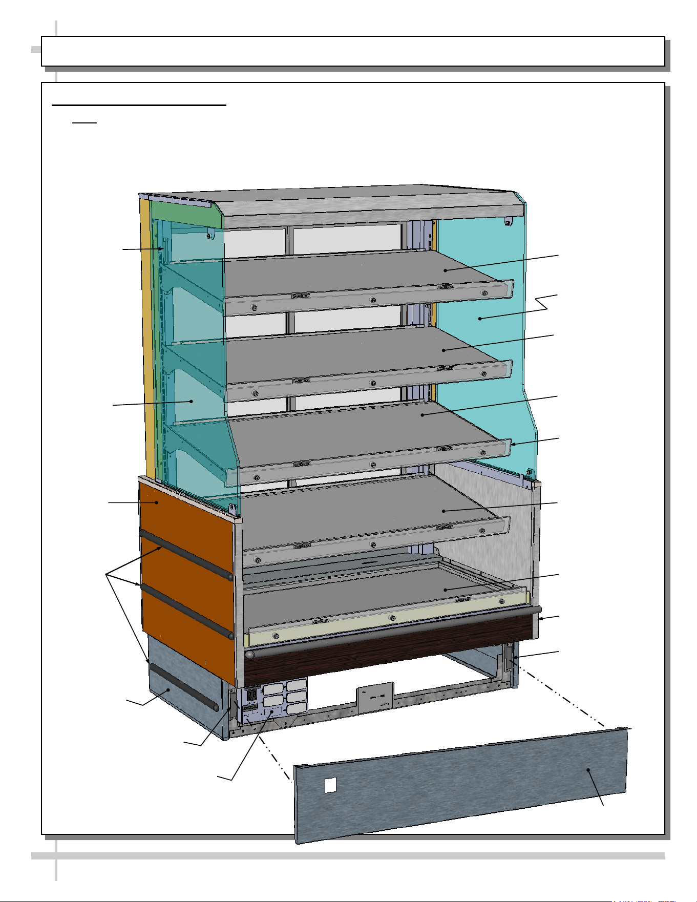
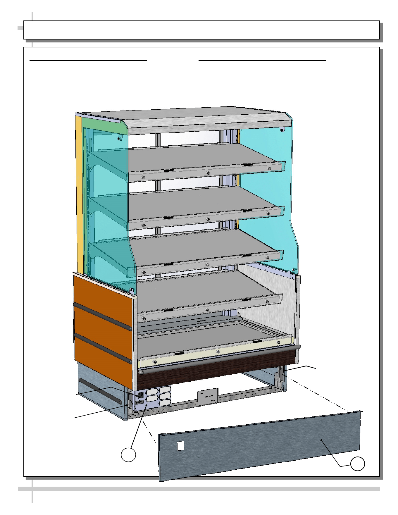
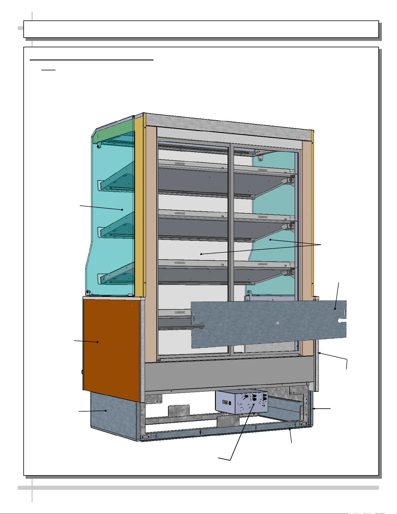
GENERAL LAYOUT: CASE FRONT
14
1. Genera Layout: Case Front
• Note: Model GHSS476H.8110 with rear sliding doors is shown.
• Solid back panel is optional.
• Illustration shown may not exactly reflect every feature or option of your particular model.
• See next page for general layout of case rear.
End
Glass
End Glass
End
Panel
Shelf 1
Shelf 2
Shelf 3
Shelf 4
Front Toe-Kick
Bumpers
(Typ.)
Deck
Lower End
Panel
End Panel
Thermometer
Electrical / Field
Wiring Box
Magnet
Magnet
Polycarbonate
Heat Shield (Typ.)
GENERAL LAYOUT, CONT’D: CASE REAR
15
End Glass
End Panel
Rear Toe-Kick
Rear Sliding
Doors
2. Genera Layout, Cont’d: Case Rear
• Note: Model GHSS476H.8110 with rear sliding doors is shown.
• Solid back panel is optional.
• Illustration shown may not exactly reflect every feature or option of your particular model.
• See previous page for general layout of case front.
End Panel
Lower End
Panel
Lower End
Panel
Splash
Guard
Electrical / Field
Wiring Box (Rear)
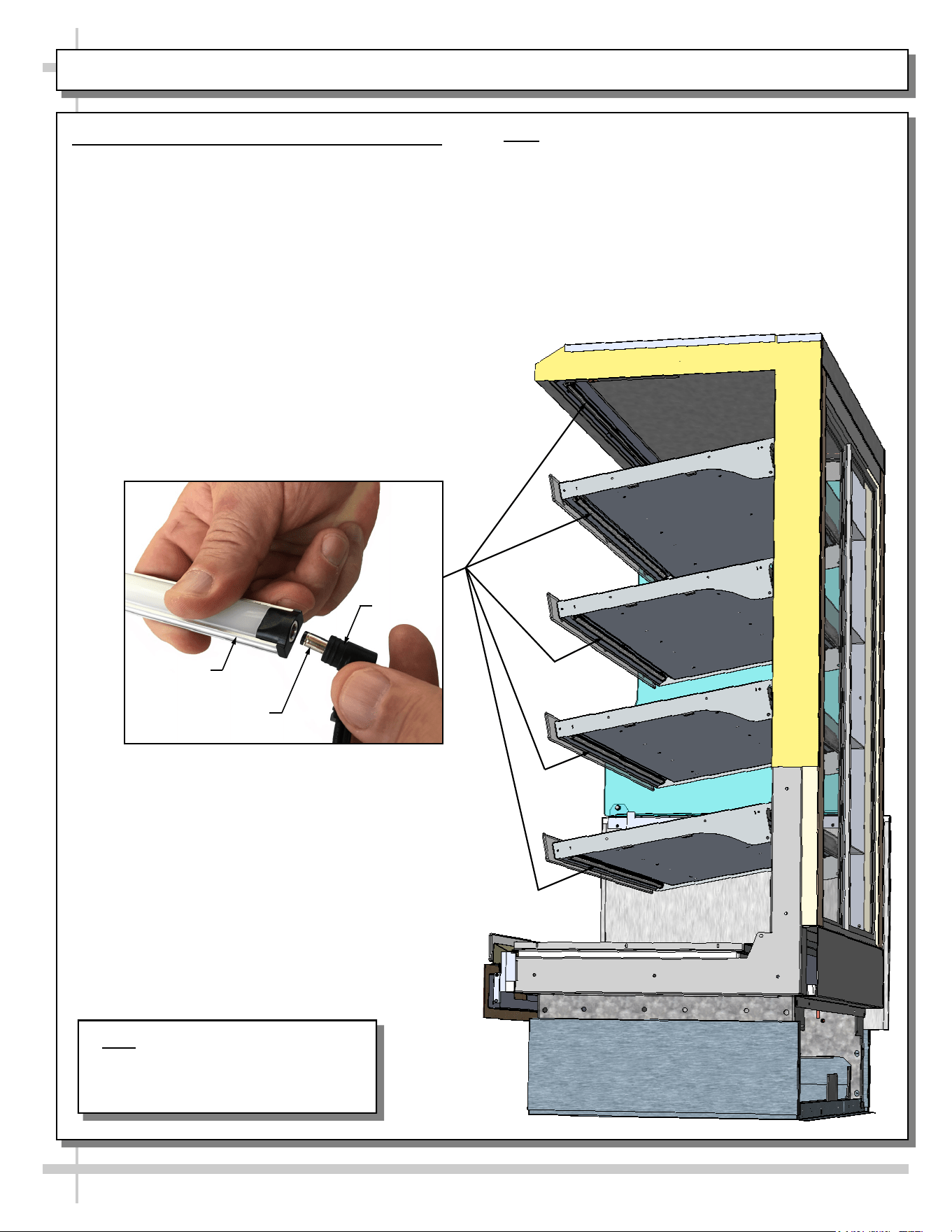
GENERAL LAYOUT, CONT’D: LED LIGHT FIXTURES / LED REMOVAL & REPLACEMENT
16
Note: Model GHSS476H.8110 With
Solid Back Panel Is Shown. It May Not
Exactly Reflect Every Feature Or
Option Of Your Particular Model.
3. General Layout, Cont’d: LED Light Fixtures
Removal of faulty LED light:
• LED lights rarely require change-out.
• To remove faulty LED light, simply grasp light
near retaining spring and carefully pull away
from its spring. Disconnect plug from LED’s
socket.
• Contact Structural Concepts’ Technical Service
Department for replacement parts (see the
Technical Service section of operating manual
for information).
Replacement of LED light:
• To replace LED light fixture, simply insert new
LED light at proper position (socket must be
near plug). Carefully snap into metal springs
so LEDs are held firmly in place.
• Note: LED light and plug must be connected in a
specific manner or they will not work.
• Make certain oval edge of plug connects to oval
edge of LED light.
• See next page for additional LED light guidelines.
LED Light
Plug
LED’s Barrel
Shaped Insert
17
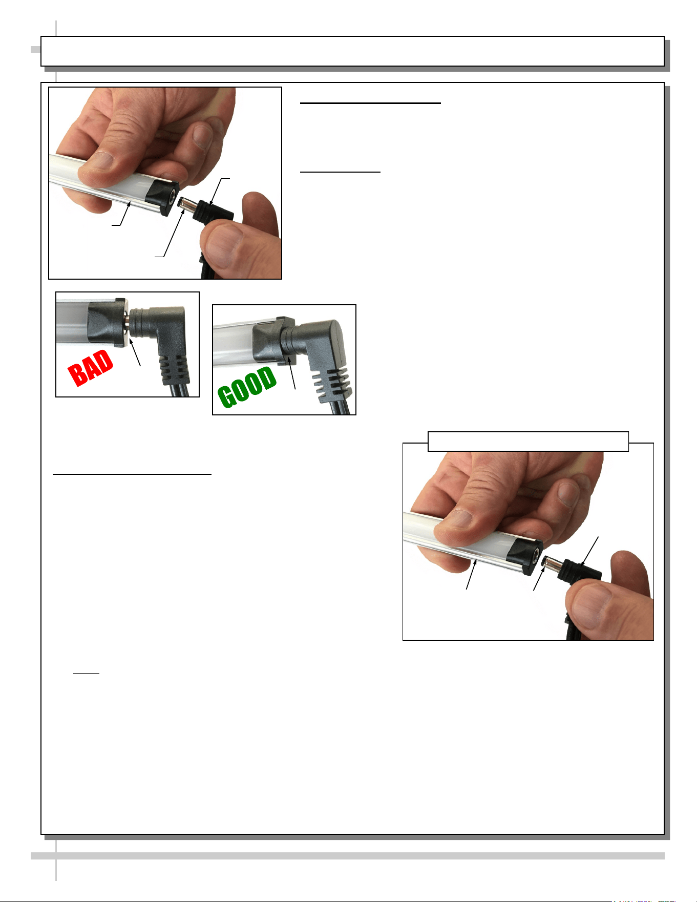
GENERAL LAYOUT, CONT’D: POWER CORD & PLUG, LED LIGHTS AND LIGHT FIXTURES
4. Power Cord and Plug
• Power cord and plug (for LED lights) locations vary
depending upon model.
• Caution! You must plugged in an approved outlet!
5. LED Lights
• LED lights are located at both header and shelving of case
(as shown below).
• Check that ALL of the light plugs are properly connected to
the LED light.
• Plug must be inserted ALL THE WAY into the LED light
orifice (with no gap) to work properly.
• See TROUBLESHOOTING section in manual if LED lights
malfunction.
No Gap
Gap
6. LED Style Light Fixtures
Removal of faulty LED light:
• LED lights rarely require change-out.
• To remove faulty LED light, simply grasp light near
retaining spring and carefully pull away from its spring.
Disconnect plug from LED’s socket.
• Contact Structural Concepts’ Technical Service
Department for replacement parts (see Technical
Service section of this manual for information).
Replacement of LED light:
• To replace LED light fixture, simply insert new LED
light at proper position (socket must be near plug).
Carefully snap into metal springs so LEDs are held
firmly in place.
• Note: LED light and plug must be connected in a
specific manner or they will not work.
• Barrel type LED light design merely requires that plug
be pushed all the way in.
• See illustrations at right.
LED Light
Plug
LED’s Barrel
Shaped Insert
Plug
LED’s Barrel
Shaped
Insert
LED
Light
“Barrel-Shaped” LED Plug & Light Fixture
18
CLEANING SCHEDULE: CASE EXTERIOR - DAILY, WEEKLY AND MONTHLY
Cleaning Daily Weekly Monthly Task
Case
Exterior
X
Wood or Laminate Surfaces
• Clean with warm, soapy water and clean cloth or sponge.
• Dry with clean cloth or paper towel.
X
Insulated Glass
• Clean outside surfaces of glass with household or commercial
glass cleaner.
• Dry with clean cloth or paper towel.
X
Stainless Steel (Case Top, Lower Panels, Etc.)
• Wash with solution of hand-dishwashing liquid detergent & warm
water or solution of baking soda and water. Rinse and polish dry
with paper towel or soft cloth.
• Do not use scouring powders or steel wool as it will scratch
surfaces.
• Brighten by polishing with cloth dipped in vinegar or in ammonia;
sprinkle baking soda on sponge and rub gently; rinse. Polish dry
with paper towel.
• Remove streaks or heat stains by rubbing with club soda.
• Caution! Do not drip or spill cleaning solution into case!
X
Under Case Cleaning
• Remove rear panel (2 screws) or front panel (no screws).
• Clean under case with vacuum and extension.
19
Caution! TURN MAIN POWER SWITCH TO “OFF”
and allow case to cool at least 45 minutes
before cleaning case interior!
Cleaning Daily Task
Case
Interior
X
Glass
• Clean inside surfaces of glass with a household or commercial glass cleaner.
• Wipe dry with clean cloth or paper towel.
X
Polycarbonate Heat Shields (At Front of Shelves)
• Use a liquid detergent and clean with a clean cloth.
• Caution! Do not use glass cleaner on polycarbonate heat shields (as it contains
ammonia). Cleaning solution with ammonia will cause heat shield to become
cloudy and crackled.
X
Shelves / Deck / Wire Racks
• Spills (Unhardened): Clean immediately to prevent hardening or “baking” of
spills. Remove wire rack (if any) to access area. Use a dry cloth, folded over
several times to clean up spills; this will prevent being burned due to steam
from wet cloth on the hot surfaces.
• Spills (Hardened): Clean hardened spills with a damp cloth dipped in
household cleaner. For stubborn stains, use firm-bristled nylon brush or
scouring pad dipped in warm, soapy water. Use spray bottle with water and
clean paper towel to wipe up residue. Wire racks may be removed, submersed
in warm to hot soapy water, and cleaned with soft-bristled brush.
CLEANING SCHEDULE, CONT’D: CASE INTERIOR - DAILY
20
CASE ISSUES TROUBLESHOOTING METHOD
Product is drying
out
Make certain that product has not exceeded allotted display time.
Authorized Personnel Only:
• Adjust temperature control settings. See START-UP, OPERATION AND
SHUTDOWN section for your model in this manual for instructions.
Product
temperature
deviates outside of
acceptable range
(product either
overheating or too
cool)
• If deck or shelving contains few or no products, a temperature reading that is
outside of range may be experienced.
• When case is properly stocked, air is trapped between product; temperatures
should maintain proper range.
• Probe thermometer may be faulty. Use a stainless steel stem-type
thermometer with dial of at least a 1-inch internal diameter and test product.
Accuracy to within 1.8 °F / 1 °C is acceptable.
Authorized Personnel Only:
• Adjust temperature control settings: See START-UP, OPERATION AND
SHUTDOWN section for your model in this manual for instructions.
System is not
operating at all
Check that unit is properly plugged in.
Confirm that the MAIN power switch is on.
If power cord is used, confirm that it is plugged into outlet.
Authorized Personnel Only:
Confirm that the utility power is on.
Authorized Personnel Only:
Check the circuit breaker box for tripped circuits.
Authorized Personnel Only:
GFCI may be required. If N.E.C. (National Electric Code) or your local code
requires GFCI (Ground Fault Circuit Interrupter) protection, you MUST use a GFCI
breaker in lieu of a GFCI receptacle.
Product is not
heating at all
Heating elements may be malfunctioning.
• Call Structural Concepts Technical Service (at last page of this manual).
• Move product to separate location until unit is repaired.
LED lights are not
working
• Check that main power switch is in the on position.
• Check that ALL of the light cords and plugs are properly connected.
See GENERAL LAYOUT, CONT’D: LED LIGHT / LED REMOVAL and
REPLACEMENT section in manual for connection instructions and illustrations.
• If case lights still do not come on, call Structural Concepts Technical Service.
Heater Fans Are
Not Operational
Authorized Personnel Only:
• Confirm that the main power switch is on.
• If main power switch is on, check that LED lights are operational.
• If LED lights are NOT operational, check utility power.
• If LED lights ARE operational and heater fans are STILL not on, contact
Structural Concepts Technical Service.
• Note: Heater fans are accessible by removing fan bracket screws.
TROUBLESHOOTING
21
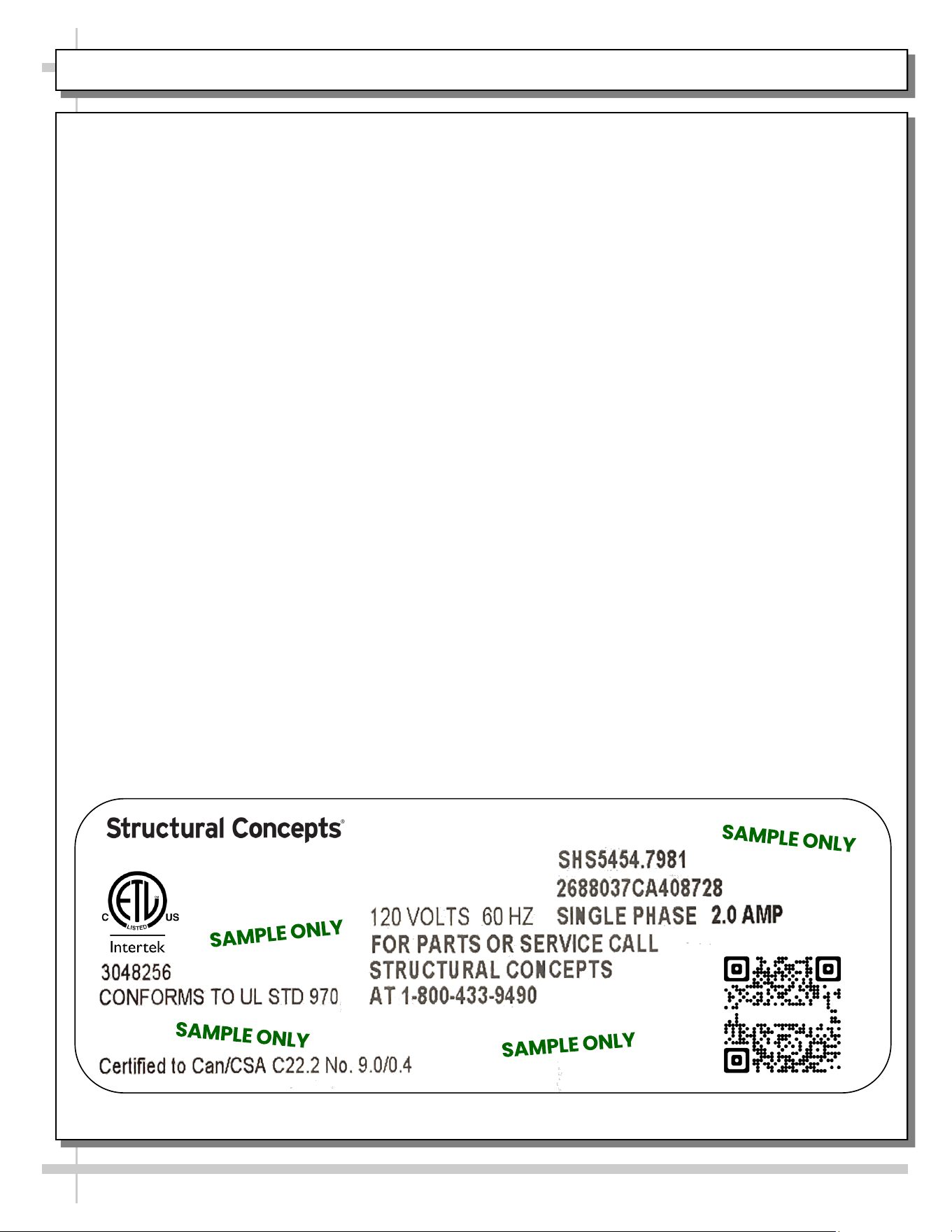
SERIAL LABEL LOCATION & INFO LISTED / TECH INFO & SERVICE - AMBIENT/HEATED CASES ONLY
Serial Label Location & Information Listed /
Technical Information & Service
• Serial labels are affixed at a wide range of places
(on the header, at case rear, behind panels or
toe-kicks, on electrical boxes, etc.).
• Serial labels contain electrical information as well
as regulatory standards to which the case
conforms.
• Sample serial label shown below.
• For additional technical information and service, see
the TECHNICAL SERVICE page in this manual for
instructions on contacting Structural Concepts’
Technical Service Department.
--- Sample Serial Label For Ambient/Heated Cases ---
Fusion
888 E. Porter Rd - Muskegon, MI 49441
Sample QR Code
SCAN FOR PRODUCT LITERATURE
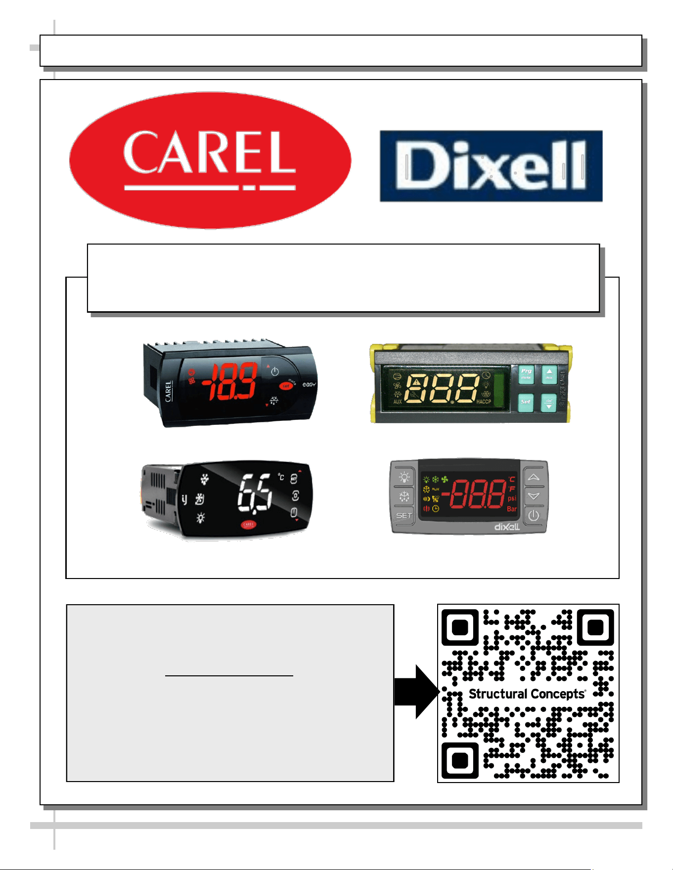
PROGRAMMABLE CONTROLLER (SELECT, CLICK ON OR SCAN QR CODE FOR INFORMATION)
22
Carel® iJF Platform
Carel® PJEZ Platform
Carel® ir33 Platform
Dixell® XM670K-XM679K Platform
To Access Information About The Programmable
Controller That Is Used On Your Case,
Follow These Instructions:
> If Viewing This Document on Smart Phone, Tablet
or Computer, Select/Click On The QR Code at Right.
> If Viewing This Document In Print (Hard Copy),
Scan The QR Code at Right With Your Smart Phone
or Tablet.
Determine Which Programmable Controller Is On Your Case (Controllers
That Are Commonly Used By Structural Concepts Are Shown Below).
Your Particular Programmable Controller May Differ.
STRUCTURAL CONCEPTS TECHNICAL SERVICE CONTACT INFORMATION & LIMITED WARRANTY
23
TECH SERVICE/WARRANTY CONTACT INFO:
1 (800) 433-9490 / EXTENSION 1
DAYS/HOURS AVAILABLE:
MONDAY - FRIDAY (CLOSED HOLIDAYS)
8:00 a.m. TO 5:00 p.m. EST
YOU MUST HAVE THE FOLLOWING INFO AVAILABLE
BEFORE CONTACTING STRUCTURAL CONCEPTS:
SERIAL NO. / MODEL NO. / STORE NO. / STORE
ADDRESS / DETAILS (PHOTOS, LEAK LOCATIONS,
DAMAGE, STORE’S AMBIENT CONDITIONS, ETC.)
To Access The Limited Warranty To Your
Case, Follow These Instructions:
> If Viewing This Document on Smart Phone,
Tablet or Computer, Select/Click On The QR
Code at Right.
> If Viewing This Document In Print (Hard
Copy), Scan The QR Code at Right With Your
Smart Phone or Tablet.