USER MANUALS\20-44626_OASIS_USER MANUAL_B(L)(D)H_B(L)(D)H_HTD_GRAB-N-GO_CASE REV G DATE: 10/14/2022
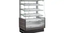
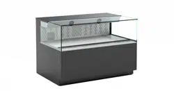
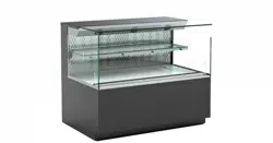
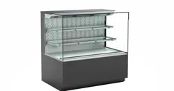
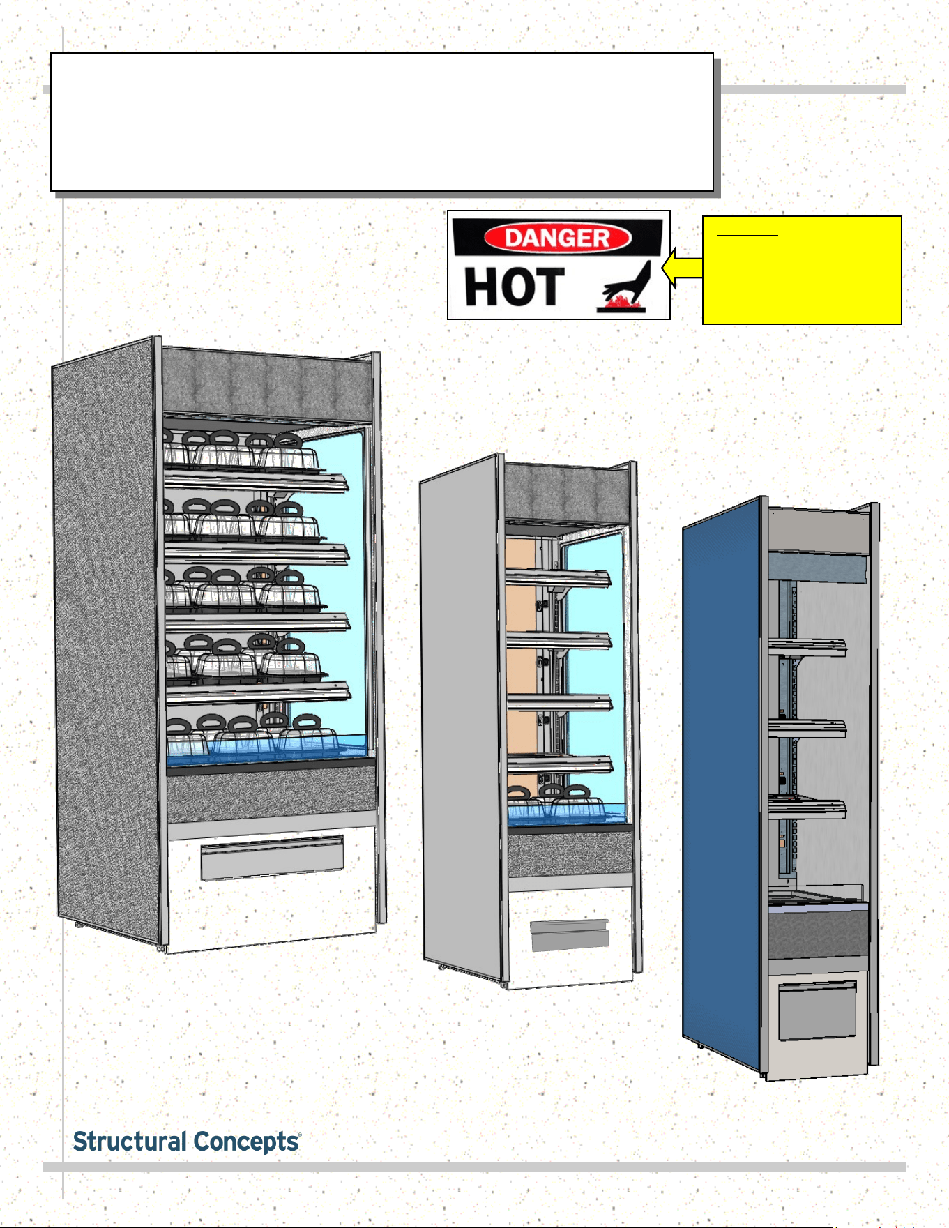
SELF-SERVICE, GRAB-N-GO
MERCHANDISERS / HEATED SHELVES /
FRONT CONTROL PANEL / CERAMIC
METAL HALIDE LIGHTS
Model B2432H
Model B3632H
Important! See Installation
Section Of This Manual For
Specifics On Confirming
Proper Placement of
“Danger-Hot” Labels on
Heated Shelves and Deck
SCC P/N
20-44626
Oasis
READ AND SAVE THESE INSTRUCTIONS
®
USER
MANUAL
Structural Concepts Corp. ∙ 888 E. Porter Rd ∙ Muskegon, MI 49441 Phone: 231.798.8888 Fax: 231.798.4960 ∙ www.structuralconcepts.com
Model B1832H
2
TABLE OF CONTENTS
OVERVIEW / TYPE / COMPLIANCE / WARNINGS / PRECAUTIONS / WIRING / PLUGS ...........…..
INSTALLATION: CASE REMOVAL / POSITIONING & ALIGNING CASE .........………………..……...
INSTALLATION, CONTINUED: IMPORTANT! HEATED SHELF LABEL PLACEMENT ..……………
INSTALLATION, CONTINUED: POSITIONING / ALIGNING / REMOVABLE FRONT & REAR
PANELS ………...……………………………………………………………………………………….
STARTUP: MAIN POWER SWITCH / LIGHTS SWITCH / FRONT PANEL REMOVAL /
ELECTRICAL RACEWAY …………………………………………………………………………….
STARTUP, CONTINUED - CONTROL PANEL EXPLODED VIEW (MODEL B2432H ONLY) ….…….
STARTUP, CONTINUED - CONTROL PANEL EXPLODED VIEW (MODEL B3632H ONLY) ..……...
STARTUP, CONTINUED - OPERATION AND SHUTDOWN (TO BE PERFORMED BY
AUTHORIZED PERSONNEL ONLY!) .......................................................................................
CERAMIC METAL HALIDE LIGHT FIXTURES / REPLACEMENT / POLYCARBONATE HEAT
SHIELDS ……………………………………………………………………………………………......
CLEANING SCHEDULE (DAILY / WEEKLY) - CASE EXTERIOR .………………………….……...…...
CLEANING SCHEDULE (DAILY / WEEKLY) - CASE INTERIOR ...……………………………………...
TROUBLESHOOTING ….…………………………………………………..………………...………………..
SERIAL LABEL & LOCATION / TECHNICAL INFORMATION / ADD’L INFORMATION …….……….
PROGRAMMABLE CONTROLLER INFORMATION.…………………………………………...…………...
TECHNICAL SERVICE CONTACT INFORMATION / WARRANTY INFORMATION ..………...……....
3-4
5
6
7
8
9
10
11
12
13
14
15
16
17
18
3
OVERVIEW
• These Structural Concepts cases should be installed and
operated according to these instructions to ensure proper
performance. Improper use will void warranty.
• This unit is designed to display products in ambient store
conditions with a maximum temperature of 80 °F (27 °C) .
DRY HEAT PURPOSES / PRE-HEATING PRODUCT, ETC.
This case is designed for dry heating operations throughout the
product area. Heat is generated from heated shelving/deck.
• Structural Concepts® heated merchandisers are designed
for packaged foods at 140 °F to 165 °F (60 °C to 74 °C).
• Product must be pre-heated to these temperatures PRIOR
TO being places in merchandiser. This case is NOT
designed to heat product from cold or ambient conditions.
• This merchandiser is designed to display perishable,
packaged products. Improper use will void warranty.
• Depending upon model, overhead incandescent lamps
may be used on shelving and header of merchandiser.
COMPLIANCE
This equipment MUST be installed in compliance with
all applicable NEC, federal, state and local
electrical and plumbing codes.
WARNING
Risk of electric shock. Disconnect power before servicing unit.
CAUTION! More than one source of electrical supply is
employed with units that have separate circuits.
Disconnect ALL ELECTRICAL SOURCES before servicing.
WARNING
ELECTRICAL
HAZARD
WARNING
Shelves and Decks Are Hot! Disconnect and allow to cool
45 minutes before cleaning or removing from case.
Ceramic metal halide lamps are hot! Turn off or disconnect and
allow to cool 45 minutes before servicing or replacing.
WARNING
HOT
SURFACE
OVERVIEW / TYPE / COMPLIANCE / WARNINGS / PRECAUTIONS / WIRING / PLUGS - PAGE 1 of 2
INTEGRATED AVERAGE PRODUCT TEMPERATURE
• These units are designed to merchandise product at an
integrated average product temperature of 150 °F (66 °C).
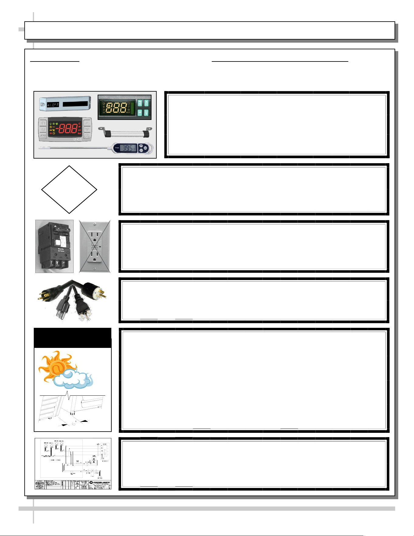
THERMOMETERS
• Thermometers in equipment reflect internal air temperature
only (not actual food temperature).
• Use probe thermometers to determine actual product
temperatures.
COMPLIANCE
• Performance issues when in violation of applicable NEC,
federal, state and local electrical and plumbing codes are
not covered by warranty. Please see below.
WARNINGS
• This page contains important warnings to prevent injury or
death. Please read carefully!
ATTENTION
CONTRACTORS
WARNING: This product can expose you to chemicals, including
Urethane (Ethyl Carbamate), which are known to the state of
California to cause cancer and birth defects or other reproductive
harm. For more information go to P65Warnings.ca.gov.
4
PRECAUTIONS
• Following are important precautions to prevent
damage to unit or merchandise. Please read carefully!
POWER CORD AND PLUG MAINTENANCE
• Caution! Risk of electric shock.
• If cord or plug becomes damaged, replace only with
cord and plug of same type.
CAUTION! LAMP REPLACEMENT GUIDELINES
Ceramic metal halide lamps reflect specific size, shape and overall
design. Any replacements must meet factory specifications.
Ceramic metal halide lamps must be replaced with similar lamps.
CAUTION
CAUTION! ADVERSE CONDITIONS / SPACING ISSUES
• Performance issues caused by adverse conditions are NOT warranted.
• To prevent damage to end panels due to condensation, apply industrial
grade silicone sealant and tightly join to opposite end panels. When not
adjoining cases, keep end panels at least 6” away from walls &
structures. Rear panels must also be kept at least 6” from walls and
structures.
• Case must not be exposed to direct sunlight or any heat source.
• To maintain proper case temperature, keep case at least 15-feet from
exterior doors, overhead HVAC vents or any air curtain disruption.
• Self-contained case clearance: 6” min. air intake / 6” min. air discharge.
CAUTION
CAUTION! POWER CORD AND PLUG MAINTENANCE
Risk of electric shock. If cord or plug becomes damaged,
replace only with cord and plug of same type.
OVERVIEW / TYPE / COMPLIANCE / WARNINGS / PRECAUTIONS / WIRING / PLUGS - PAGE 2 of 2
CAUTION! GFCI BREAKER USE REQUIREMENT
If N.E.C. (National Electric Code) or your local code
requires GFCI (Ground Fault Circuit Interrupter) protection,
you MUST use a GFCI breaker in lieu of a GFCI receptacle.
WIRING DIAGRAM FORMAT & LOCATION
• Each case has its own wiring diagram folded & in its own packet.
• Wiring diagram placement may vary; it may be placed near ballast
box, field wiring box, raceway cover, or other related location.
CAUTION! DO NOT RELY ON THERMOMETERS OR
THERMOSTATS FOR PRODUCT (FOOD) TEMPERATURES.
• Thermometers & thermostats reflect air temperatures ONLY.
• For ACTUAL product (food) temperatures, use a calibrated food
probe thermometers ONLY.
• For accurate readings, DO NOT use infrared food thermometers.
5
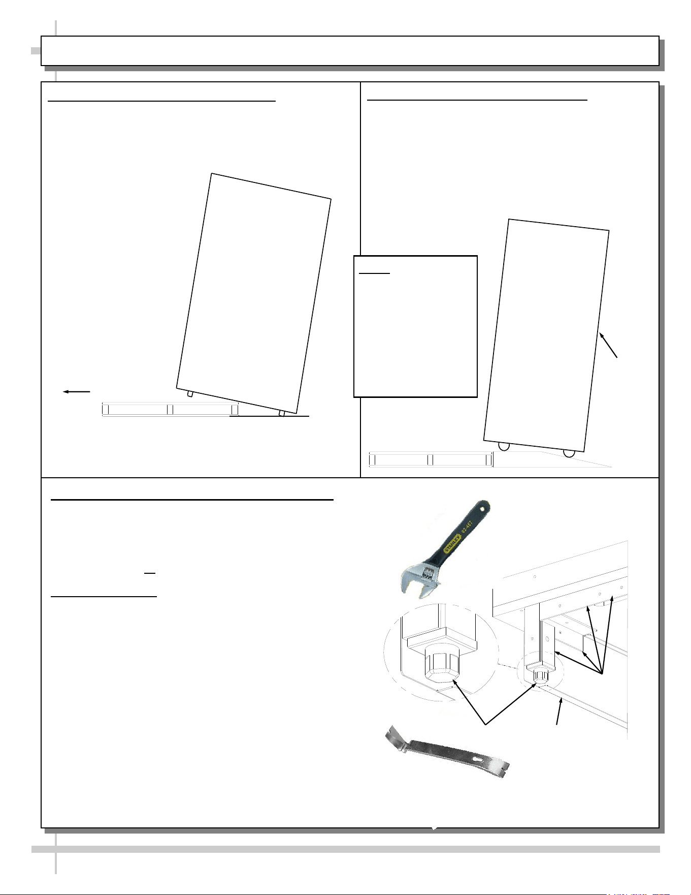
INSTALLATION: CASE REMOVAL / POSITIONING & ALIGNING CASE
Pry Bar
Base
Frame
Leveler
Adjustable
Wrench
Toe-Kick
3. Position & Align Case Alongside Other Cases
• Before adjusting levelers, make certain that the
case is in proper position and, if required, aligned
with adjoining case(s).
• This may require the repositioning of the case you
are installing or the already positioned case(s).
4. Adjust Levelers
• After case is in proper position, adjust case so it is
level and plumb (see illustration at right).
• You may need to remove front and/or rear
Toe-kick to access levelers.
• Use adjustable wrench to adjust leveler.
• Depending upon case weight it may be necessary
to use a pry bar to accomplish this task.
• Do not use pry bar on toe-kick as it may buckle.
• Do not use pry bar on end panel as it may chip.
• Use pry bar ONLY on base frame to avoid
damaging case.
• See illustration and photos at right.
1. Remove Case From Skid (Levelers)
• Remove shipping brace that may be securing
case to skid.
• Support case to prevent tipping.
• Caution! Levelers can be damaged if case hits
floor with heavy force!
Case can be repositioned with pallet truck when front lower
panel is removed. Blocking may be necessary to obtain
adequate height.
Slide Skid Out
• Carefully slide unit
to rear of skid and
tip backward off
skid.
• Illustration may
not reflect every
feature or option
of your particular
case.
2. Remove Case From Skid (Casters)
Remove shipping brackets that may be securing
casters to skid
• Place ramp up against skid (to allow case to
smoothly slide off from skid).
• Maintain support of case at all times or center
of gravity may cause case to fall.
• Unlock Casters. Roll unit to rear of skid.
Ramp
Roll down ramp
and off from skid.
Support
while
rolling
case
down
ramp.
Note: Illustrations
shown reflect a
general outline of
sample cases and
do not reflect
features or
options of your
particular model.
6
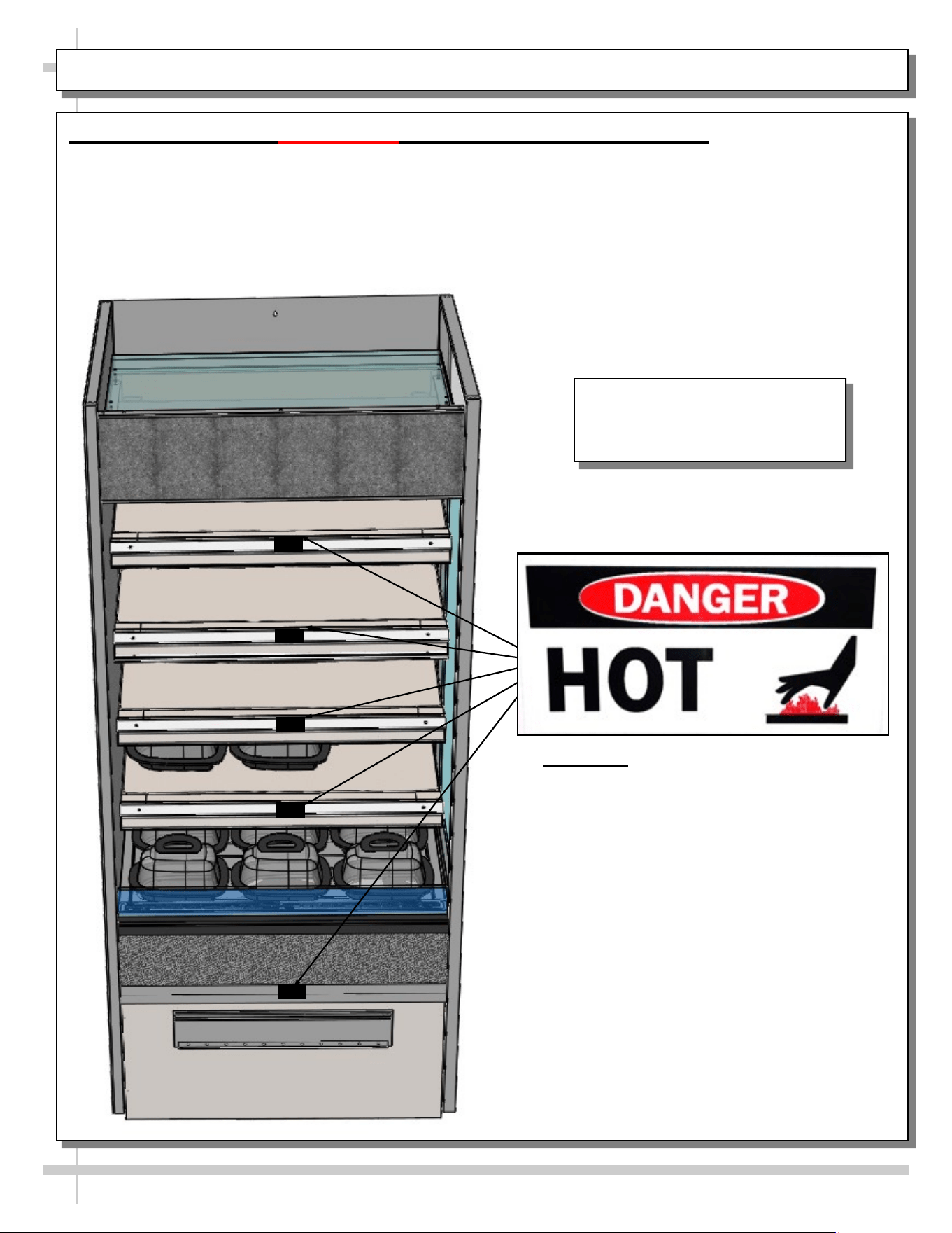
INSTALLATION, CONTINUED: IMPORTANT! HEATED SHELF LABEL PLACEMENT
Important! Check That “Caution-Hot”
Labels Are Placed On
Heated Shelves and Deck
As Shown In Illustration At Left
5. Important! Check That “Caution-Hot” Labels Are Properly Attached To Case
• Shelves can get extremely hot and cause severe burns.
• Illustration below shows proper placement of “Caution-Hot” labels.
• At least ONE label must be placed on each shelf (as shown below). Wide units may have two or more
labels placed on shelves and deck.
• If labels are not properly attached, contact Structural Concepts to obtain labels. See SCC TECHNICAL
SERVICE CONTACT INFORMATION section at last page in manual.
Illustration Shown May Not
Exactly Reflect Every Feature or
Option of Your Particular Case.
7
INSTALLATION, CONTINUED: POSITIONING / ALIGNING / REMOVABLE FRONT & REAR PANELS
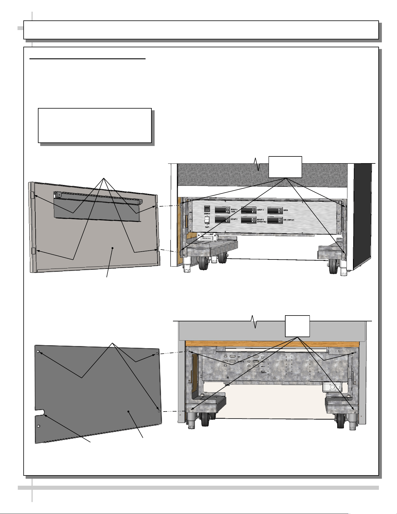
6. Removable Front & Rear Panels
• Front panels are removable by simply sifting up and off (via slot/hook method). See illustration below.
• Rear panels are removable by accessing four (4) screws. See illustration below.
• Return to case in reverse order it was removed.
--- Typical Case Rear ---
--- Sample Case Front ---
Typical Rear
Panel
Screw Holes
(Typical)
Power Cord
Slot
Screw
Holes
Typical Front
Panel
Panel Slots
Panel
Hooks
Illustrations Shown May Not
Exactly Reflect Every Feature or
Option of Your Particular Case.
8
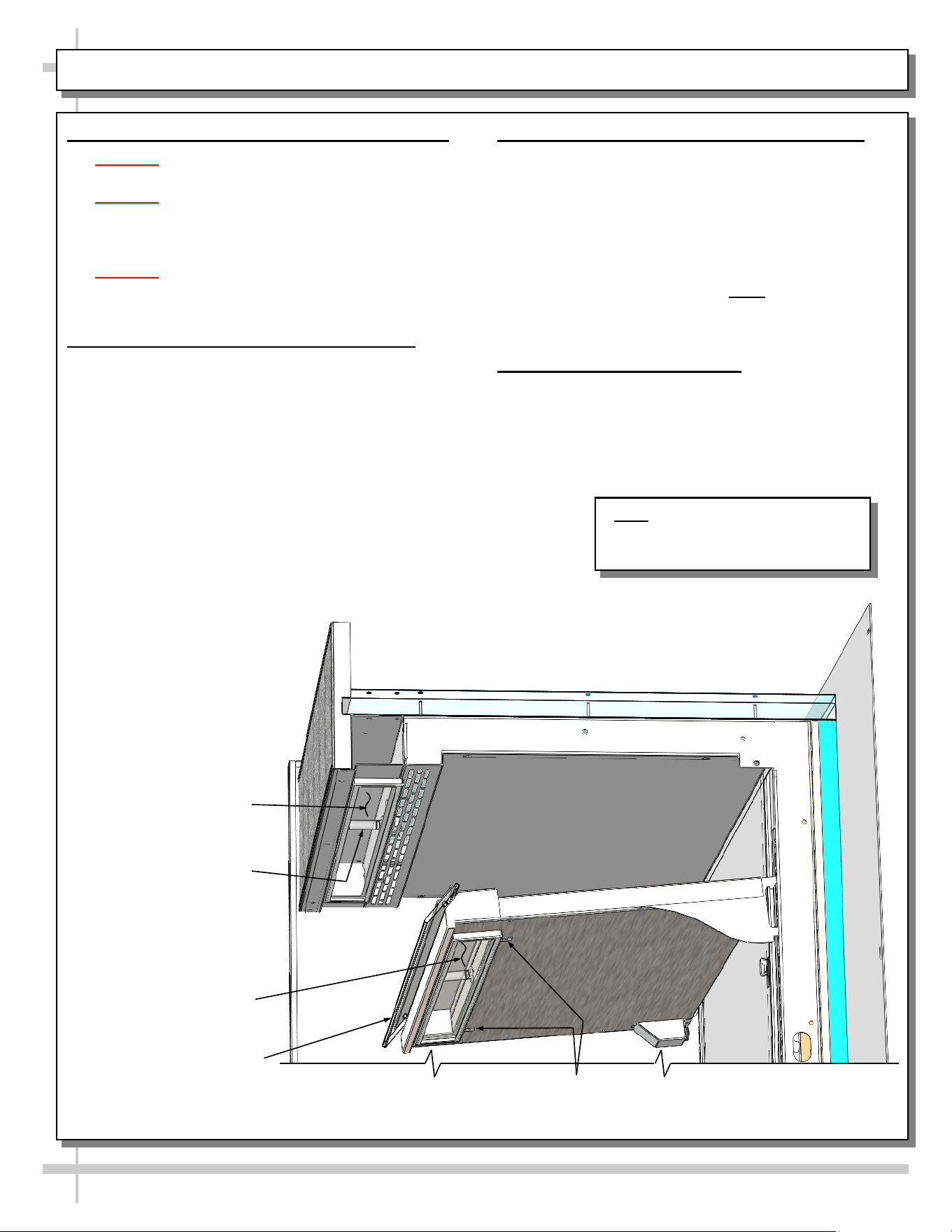
STARTUP: MAIN POWER SWITCH / LIGHTS SWITCH / FRONT PANEL REMOVAL / ELEC. RACEWAY
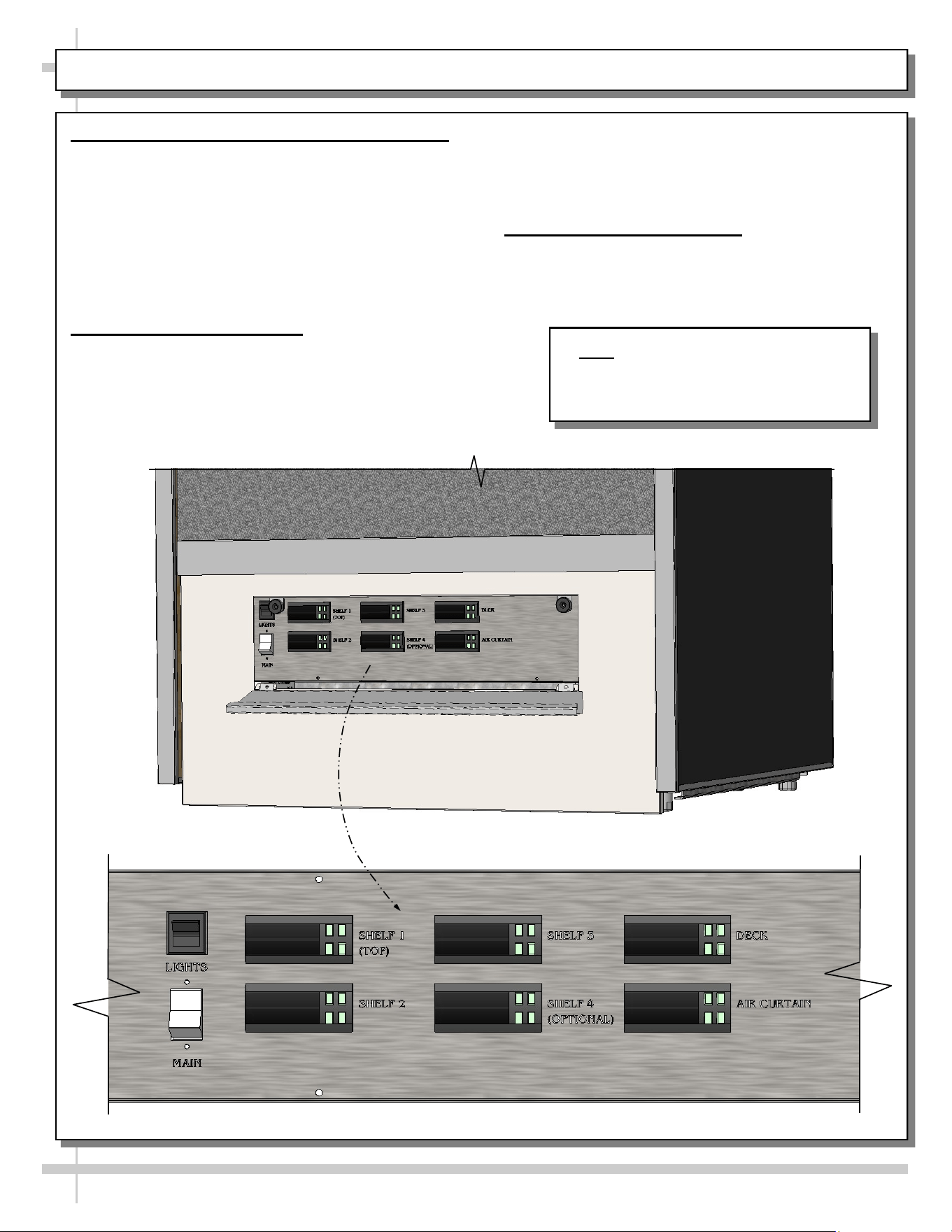
1. Front Flip-Down Door / Main Power / Lights
• Models have flip-down door with magnet features
allowing access to controls at front of case.
• Main power switch, lights and pre-heat buttons are
accessible when down-down door is lowered.
• When main power switch is turned on, power to
entire case is provided.
• When light switch is turned on, all lights in entire
case will turn on.
2. Front/Rear Panel Removal
• To remove front (or rear) panels, lift front panel up
and off case. No screw removal is required to
remove front panel.
• Certain models employ magnets along with slot/
hook method on front/rear panels.
• Replace front/rear panels in same manner they
had been removed.
3. Electrical Raceway Access
• Directly behind front (or rear) panel is the
electrical raceway.
Note: Model B3632H Is Shown With
Flip-Down Door Removed. General
Layout Is Applicable To All Models
Represented In This Operating Manual.
9
STARTUP, CONTINUED - CONTROL PANEL EXPLODED VIEW (MODEL B2432H ONLY)
Model B2432H - Control Panel Exploded View
1. Field Access Box
• Field access box is at lower-left of control panel.
2. Main Power / Lights
• Main power switch and lights switch are at right
of control panel (as shown below).
3. Shelves and Deck Heater Controls
• Heater controls to shelves and deck are on
control panel.
• See Carel® Controller information in this manual
for specifics.
Shelf One
Shelf Three
Shelf Two
Shelf Four
(Optional)
Deck
10
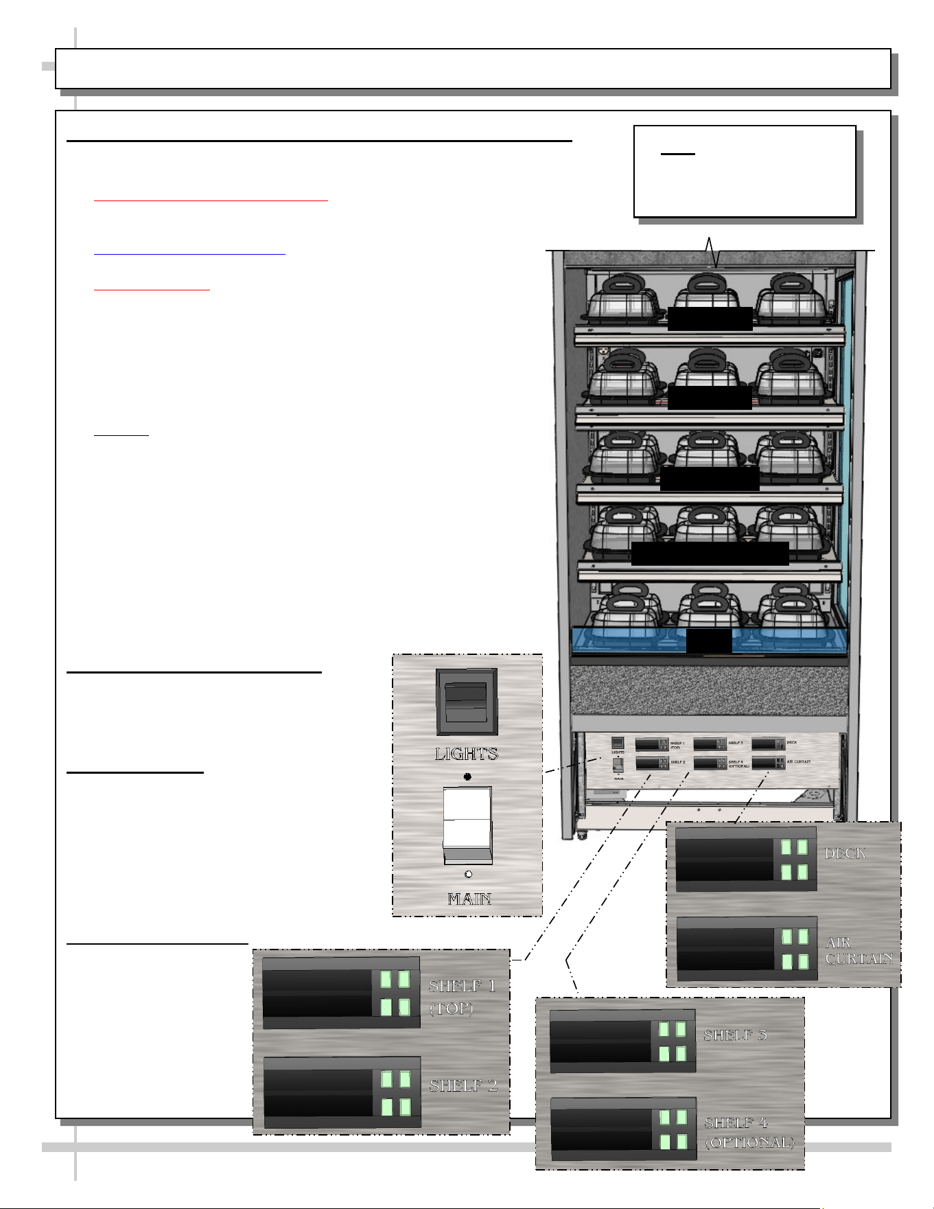
STARTUP, CONTINUED - CONTROL PANEL EXPLODED VIEW (MODEL B3632H ONLY)
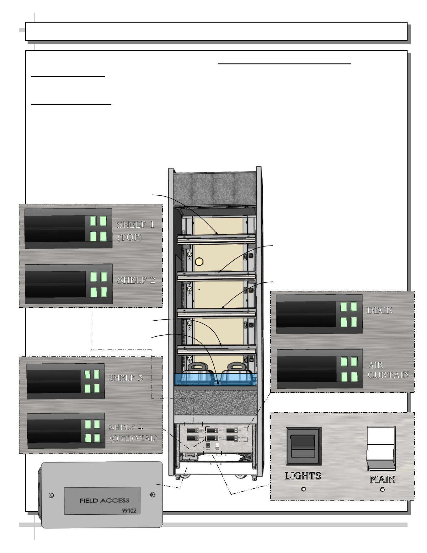
Model B3632H - Control Panel Exploded View
1. Field Access Box
• Field access box is at lower-left of control panel.
2. Main Power / Lights
• Main power switch and lights switch are at right
of control panel (as shown below).
3. Shelves and Deck Heater Controls
• Heater controls to shelves and deck are on
control panel.
• See Carel® Controller information in this manual
for specifics.
Shelf Three
Shelf Two
Shelf Four (Optional)
Deck
Shelf One
11
STARTUP, CONTINUED - OPERATION AND SHUTDOWN (AUTHORIZED PERSONNEL ONLY!)
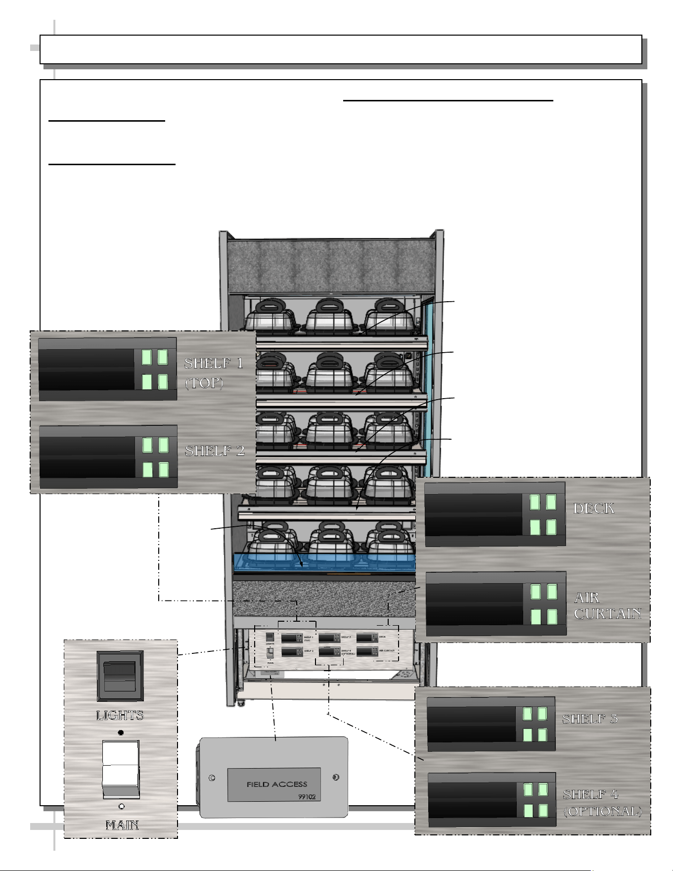
1. Merchandiser Daily Start-Up (For Authorized Personnel Only)
• Lift up hinged door at case front. Both switches should be in off position.
• Turn main power switch / lamp switch on.
• Inoperative Dashboard Notations: Markings of “Well,” “Overhead” and
“Pre-Heat” may on faceplates. These fuctions are NOT used on these
Note: Model B3632H Is
Shown. General Layout Is
Applicable To All Models
Represented In Manual.
models and are to be disregarded.
• Ceramic Metal Halide Note: Lamps may take up to 15
minutes to fully illuminate.
• Cautionary Note: Deck, shelving and overhead lights are hot!
Do not touch unless dials have been turned off & area is cool!
• Each programmable controller controls a particular shelf as
well as the deck.
• Programmable controllers are pre-set at the factory and
should RARELY require adjustment.
• Allow 15-20 minutes for temperature to reach desired
temperature before placing product on shelves/deck.
• Caution! Food MUST BE cooked PRIOR to being placed in
the case. Food should be heated to a temperature of
between 150 °F to 160 °F (65.6 °C - 71 °C) prior to placing in
case. Food temperature must NOT be allowed to be below
FDA guideline of 140 °F (60 °C).
• Use probe to check food temperature before placing in case.
• After product is placed in case, check product temperature
(again) after one hour to verify that proper food temperatures
are maintained.
• Should product temperatures be outside of range, adjust
temperature controls for that particular shelf or deck up or
down by one number.
• Check food temperature again after one hour.
2. Temperature Control Settings
• Temperatures of all food products are to
be at 140 °F to 165 °F (60 °C to 74 °C),
for decks and shelves (including
optional shelf #4).
3. Operating Tips
• When restocking, place new product at
back and rotate older product to front of
case.
• Display product expected to sell within
4 hours.
• Clean up residue immediately. Case will
cause spills and debris to harden to
surface!
4. Shutting Down Case
• Remove all product
from case. Turn
main power switch
“OFF.”
• Allow case to cool
for 45 minutes
before cleaning.
Shelf One
Shelf Four (Optional)
Deck
Shelf Two
Shelf Three
12
1. Ceramic Metal Halide Light Fixture Warnings
• Warning! Turn off lights switch before replacing
ceramic metal halide lights.
• Warning! Lamps are manufactured to resist
breakage. Replace with same wattage lamp that is
similarly manufactured. If uncertain of wattage,
refer to label on case for specifics.
• Warning! As ceramic metal halide lamps may heat
up entire light fixture area, allow case to cool down
for 45 minutes before accessing.
2. Removal of Ceramic Metal Halide Lamps
• Loosen lamp access screws. Allow lamp cover to
drop downward.
• Wrap lamp in cloth or paper towel (as added
protection from warm lamp).
• Grasp lamp with firm grip and pull straight outward
(without bending or twisting lamp).
CERAMIC METAL HALIDE LIGHT FIXTURES / REPLACEMENT / POLYCARBONATE HEAT SHIELDS
3. Installation of Ceramic Metal Halide Lamps
• Wrap new lamp in cloth or paper towel (as
added protection from warm lamp AND to
prevent oils from skin from getting on lamp).
• Firmly grasp and carefully insert into open
socket.
• Raise lamp cover back into place. Tighten
screws that had been loosened.
• Turn lamp switch back on. Note: Ceramic metal
halide lamps may take up to 15 minutes to gain
full illumination.
4. Polycarbonate Heat Shields
• Polycarbonate heat shields can heat up to
extremely hot temperatures.
• Allow to cool before touching or cleaning.
Ceramic Metal Halide
Heat Lamp (Typical)
Polycarbonate Heat
Shield (Typical)
Glass Cover
(Typical)
Glass Cover (Typical)
Lamp Access Screws (Typ.)
Note: Illustration Shown May Not
Exactly Reflect Every Feature or
Option of Your Particular Case
13
CLEANING SCHEDULE (DAILY / WEEKLY) - CASE EXTERIOR
Cleaning Daily Weekly Task
Case
Exterior
X
Wood or Laminate Surfaces
• Clean with warm, soapy water and clean cloth or sponge.
• Dry with clean cloth or paper towel.
X
Insulated Glass
• Clean outside surfaces of glass with household or commercial glass
cleaner.
• Dry with clean cloth or paper towel.
X
Stainless Steel (case top, sides, front, rear, etc.)
• Wash with solution of hand-dishwashing liquid detergent & warm water or
solution of baking soda and water. Rinse and polish dry with paper towel or
soft cloth.
• Do not use scouring powders or steel wool as it will scratch surfaces.
• Brighten by polishing with cloth dipped in vinegar or in ammonia; sprinkle
baking soda on sponge and rub gently; rinse. Polish dry with paper towel.
• Remove streaks or heat stains by rubbing with club soda.
• Caution! Do not drip or spill cleaning solution into case!
X
Under Case Cleaning
Remove front or rear panel. Clean under case with vacuum.
14
Caution! TURN MAIN POWER SWITCH TO “OFF”
and allow case to cool at least 45 minutes
before cleaning case interior!
Cleaning
Daily
Weekly
Task
Case
Interior
X
Glass
Clean inside surfaces of glass with a household or commercial glass
cleaner. Wipe dry with clean cloth or paper towel.
Polycarbonate Heat Shields (At Each Shelf)
• Use a liquid detergent and clean with a clean cloth.
• Caution! Do not use glass cleaner on polycarbonate heat shields. Such
cleaning solution will cause heat shield to become cloudy and crackled.
X
Shelves / Decks / Wire Racks
Spills (Unhardened): Clean immediately to prevent hardening or “baking”
of spills. Remove wire rack (if any) to access area. Use a dry cloth, folded
over several times to clean up spills; this will prevent being burned due to
steam from wet cloth on the hot surfaces.
Spills (Hardened): Clean hardened spills with a damp cloth dipped in
household cleaner. For stubborn stains, use firm-bristled nylon brush or
scouring pad dipped in warm, soapy water. Use spray bottle with water and
clean paper towel to wipe up residue. Wire racks may be removed,
submersed in warm to hot soapy water, and cleaned with soft-bristled
brush.
X
Ceramic Metal Halide Glass Covers
After case has been allowed to cool 45 minutes, use household or
commercial glass cleaner and clean cloth (or paper towel) to remove any
smudges, fingerprints, or oily residue from glass surface.
CLEANING SCHEDULE (DAILY / WEEKLY) - CASE INTERIOR
15
CASE ISSUES TROUBLESHOOTING METHOD
Product is drying out Make certain that product has not exceeded allotted display time.
Authorized Personnel Only:
• Adjust temperature control settings. See START-UP, OPERATION AND
SHUTDOWN section for your model in this manual for instructions.
Product temperature
deviates outside of
acceptable range
(product either
overheating or too
cool)
• If deck or shelving contains few or no products, a temperature reading that is
outside of range may be experienced.
• When case is properly stocked, air is trapped between product; temperatures
should maintain proper range.
• Probe thermometer may be faulty. Use a stainless steel stem-type
thermometer with dial of at least a 1-inch internal diameter and test product.
Accuracy to within 1.8 °F / 1 °C is acceptable.
Authorized Personnel Only:
• Adjust temperature control settings: See START-UP, OPERATION AND
SHUTDOWN section for your model in this manual for instructions.
System is not
operating at all
Check that unit is properly plugged in.
Confirm that the MAIN power switch is on.
If power cord is used, confirm that it is plugged into outlet.
Authorized Personnel Only:
Confirm that the utility power is on.
Authorized Personnel Only:
Check the circuit breaker box for tripped circuits.
Authorized Personnel Only:
GFCI may be required. If N.E.C. (National Electric Code) or your local code
requires GFCI (Ground Fault Circuit Interrupter) protection, you MUST use a
GFCI breaker in lieu of a GFCI receptacle.
Product is not heating
at all
Heating elements may be malfunctioning.
• Call Structural Concepts Technical Service (at last page of this manual).
• Move product to separate location until unit is repaired.
Ceramic metal halide
lamps are not working
Caution! Case is extremely hot! Turn off main power switch and allow
lamps to cool for 45 minutes before touching light bulbs.
• Be sure ALL lamps are inserted properly (and all the way for proper
connection to take place).
• Check that bulbs are not burned out.
• It may take 15 minutes for ceramic metal halide lamps to fully illuminate.
TROUBLESHOOTING
16
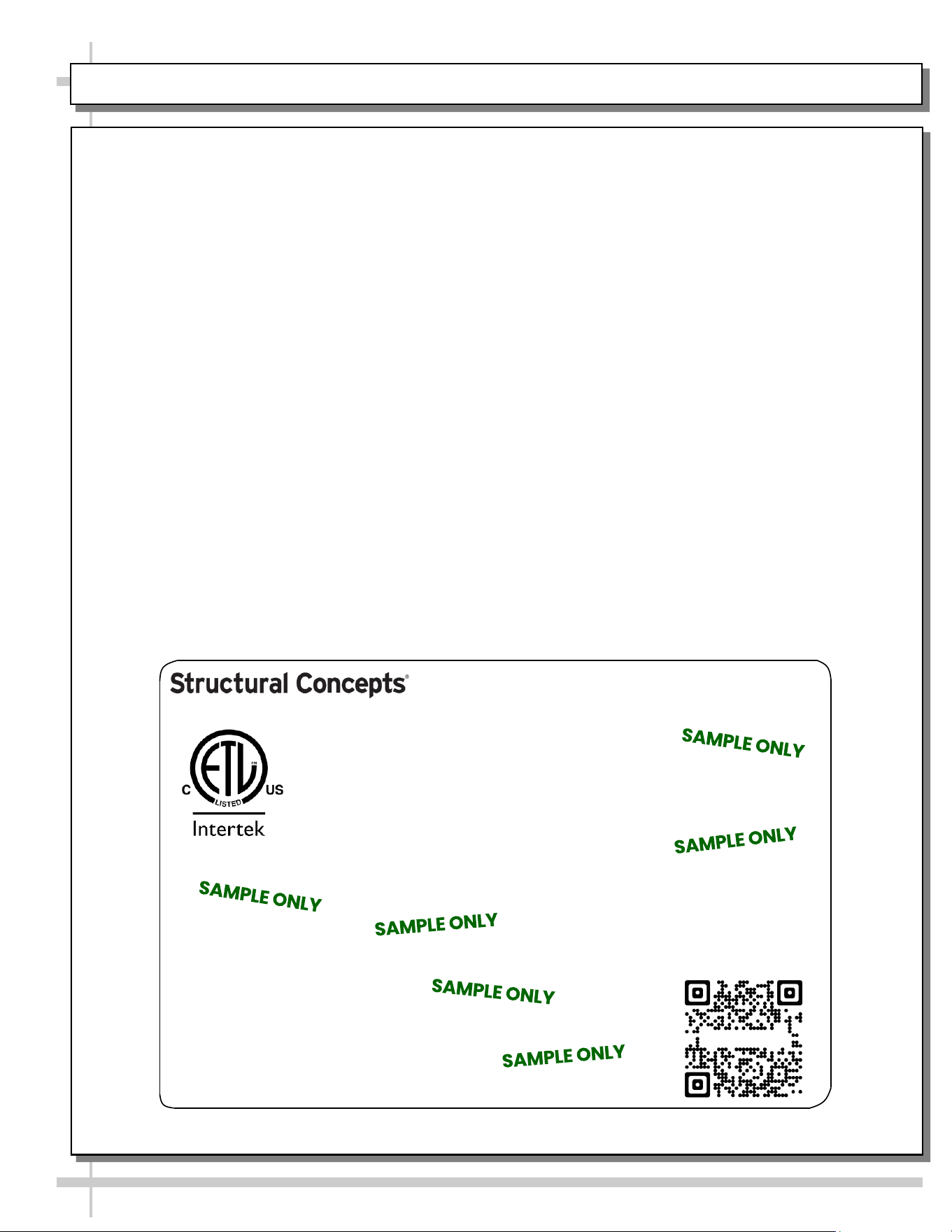
SERIAL LABEL LOCATION & INFO LISTED / TECH INFO & SERVICE - AMBIENT/HEATED CASES ONLY
--- Sample Serial Label For Ambient/Heated Cases ---
MODEL NRS3648RXV-SAMPLE
SERIAL NO. 12345X30DZ098765
888 E. Porter Rd - Muskegon, MI 49441
3048256
Conforms to UL Std. 65
CERTIFIED TO CAN/CSA
STD C22.2 NO 120
120 VOLTS 60HZ
FOR PARTS OR SERVICE CALL
STRUCTURAL CONCEPTS
AT 1-800-433-9489
SINGLE PHASE 1.84 AMPS
Serial Label Location & Information Listed /
Technical Information & Service
• Serial labels are affixed at a wide range of places
(on the header, at case rear, behind panels or
toe-kicks, on electrical boxes, etc.).
• Serial labels contain electrical information as well
as regulatory standards to which the case
conforms.
• Sample serial label shown below.
• For additional technical information and service, see
the TECHNICAL SERVICE page in this manual for
instructions on contacting Structural Concepts’
Technical Service Department.
Sample QR Code
SCAN FOR PRODUCT LITERATURE
Reveal
Harmony
Fusion
Impulse
Addenda
Blend
Grocerant
Oasis
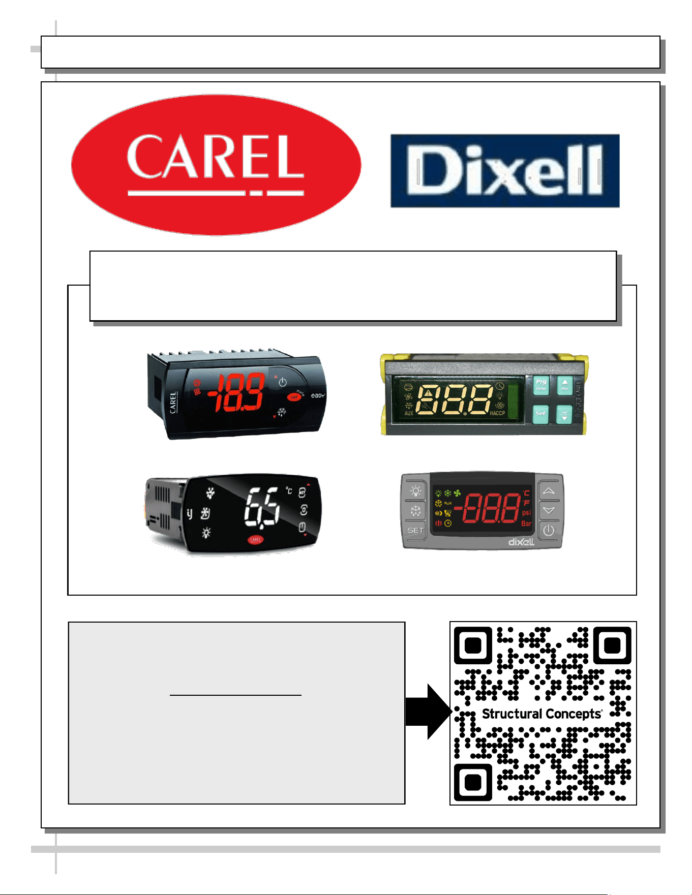
PROGRAMMABLE CONTROLLER (SELECT, CLICK ON OR SCAN QR CODE FOR INFORMATION)
17
Carel® iJF Platform
Carel® PJEZ Platform
Carel® ir33 Platform
Dixell® XM670K-XM679K Platform
To Access Information About The Programmable
Controller That Is Used On Your Case,
Follow These Instructions:
> If Viewing This Document on Smart Phone, Tablet
or Computer, Select/Click On The QR Code at Right.
> If Viewing This Document In Print (Hard Copy),
Scan The QR Code at Right With Your Smart Phone
or Tablet.
Determine Which Programmable Controller Is On Your Case (Controllers
That Are Commonly Used By Structural Concepts Are Shown Below).
Your Particular Programmable Controller May Differ.
STRUCTURAL CONCEPTS TECHNICAL SERVICE CONTACT INFORMATION & LIMITED WARRANTY
18
TECH SERVICE/WARRANTY CONTACT INFO:
1 (800) 433-9490 / EXTENSION 1
DAYS/HOURS AVAILABLE:
MONDAY - FRIDAY (CLOSED HOLIDAYS)
8:00 a.m. TO 5:00 p.m. EST
YOU MUST HAVE THE FOLLOWING INFO AVAILABLE
BEFORE CONTACTING STRUCTURAL CONCEPTS:
SERIAL NO. / MODEL NO. / STORE NO. / STORE
ADDRESS / DETAILS (PHOTOS, LEAK LOCATIONS,
DAMAGE, STORE’S AMBIENT CONDITIONS, ETC.)
To Access The Limited Warranty To Your
Case, Follow These Instructions:
> If Viewing This Document on Smart Phone,
Tablet or Computer, Select/Click On The QR
Code at Right.
> If Viewing This Document In Print (Hard
Copy), Scan The QR Code at Right With Your
Smart Phone or Tablet.