REV F DATE: 06/23/2023 USER MANUALS\21-26055_REVEAL_USER MANUAL_NR(L)(H)HSSV_HTD_SELF-SVC_FREE-STDG_CASE
SCC P/N
21-26055
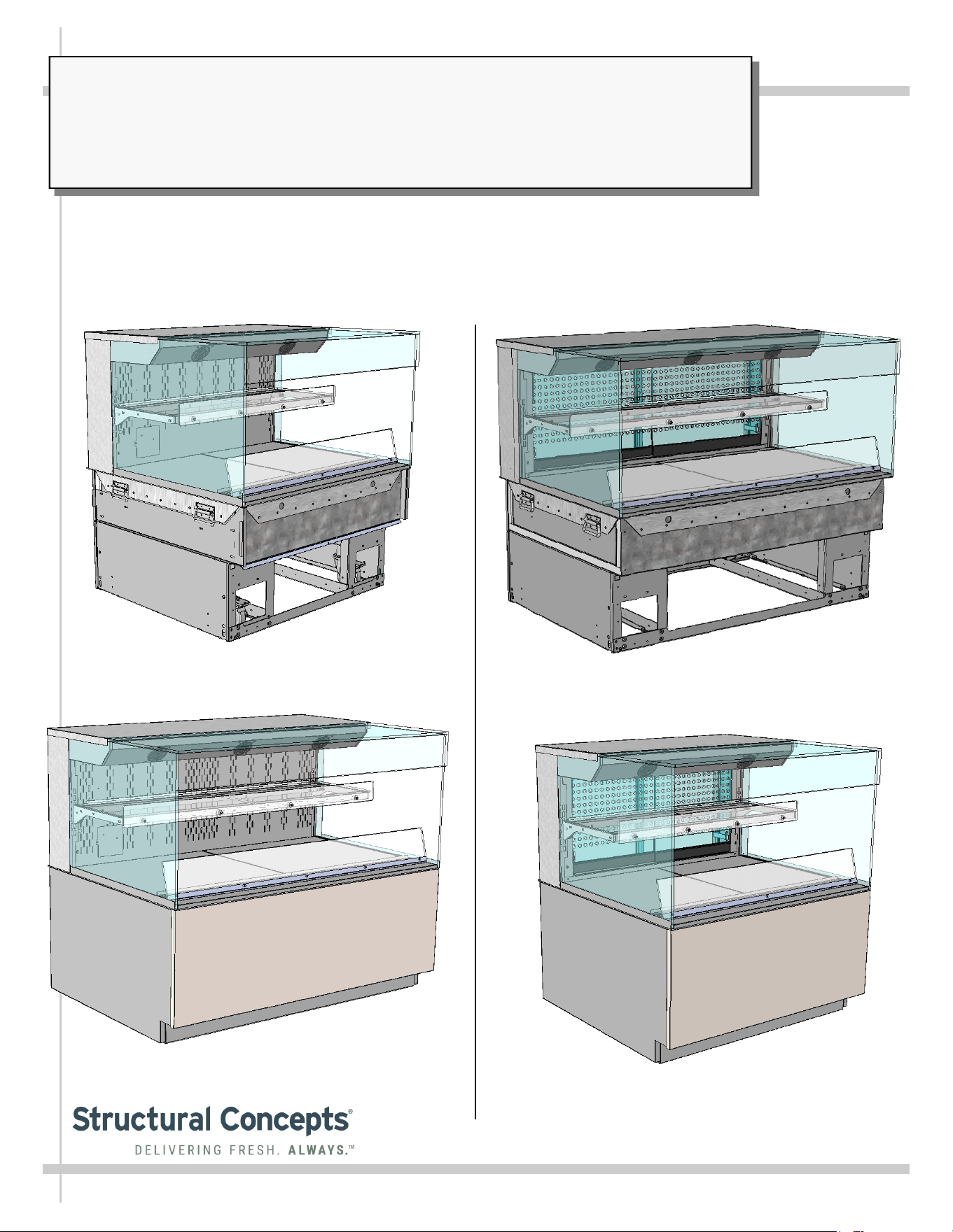
REVEAL® FREE-STANDING SELF-SERVICE HEATED MERCHANDISERS
> REAR SLIDING DOOR UNITS WITH PERFORATED PLENUMS THAT SLIDE IN TANDEM WITH DOORS
> SOLID BACK UNITS WITH FIXED METAL PERFORATED PLENUM
> CAUTION! DO NOT PUSH OR PULL ON UPPER GLASS ENCLOSURE!
> ONLY USE HANDLES (AT EACH END OF CASE) TO PUSH OR PULL CASE INTO POSITION!
> SEE PAGES 10-11 FOR FRONT/SIDE PANEL/REAR PANELS & TOE-KICK ATTACHMENT INSTRUCTIONS
REVEAL
®
READ AND SAVE THESE INSTRUCTIONS
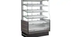
Model NR3640HSSV Free Standing Unit With Rear
Sliding Doors Shown WITH Front/Side/Rear
Cladding and Toe-Kick Attached
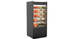
Model NR4840HSSV Free Standing Unit With Rear
Sliding Doors Shown WITHOUT Front/Side/Rear
Cladding And Toe-Kick Attached
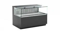
Model NR4840HSSV Free Standing Unit With
Solid Back Shown WITH Front/Side/Rear
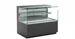
Model NR3640HSSV Free Standing Unit With
Solid Back Shown WITHOUT Front/Side/Rear
Cladding and Toe-Kick Attached
USER
MANUAL
Structural Concepts Corp. ∙ 888 E. Porter Rd ∙ Muskegon, MI 49441 Phone: 231.798.8888 Fax: 231.798.4960 ∙ www.structuralconcepts.com
2
TABLE OF CONTENTS
TABLE OF CONTENTS …………………………………………………………………………………...…...
REVEAL® FREE STANDING HEATED SELF-SERVICE MODEL APPLICABILITY &
DIMENSIONS ....………………………………………………………………………………………..
OVERVIEW / DISPLAY TYPE I vs. II / COMPLIANCE / WARNINGS / PRECAUTIONS ……………...
INSTALLATION: TOE-KICK REMOVAL / DISCONNECTING CASE FROM SKID ...……..…………...
INSTALLATION, CONT’D.: CASTER ADJUSTMENT / LOCK / UNLOCK / CASE REMOVAL
FROM SKID .………………………………………………………………………………...………….
INSTALLATION, CONT’D: SHELVING ASSEMBLY COMPONENTS ...………………………………...
INSTALLATION, CONT’D: PLUG IN UNIT / TURN ON MAIN POWER SWITCH AND LED LIGHTS
SWITCH …………………………………………………………….....……………………………..….
INSTALLATION, CONT’D: ATTACHING FRONT PANEL COMPONENTS …………………....……….
INSTALLATION, CONT’D: ATTACHING SIDE PANELS AND REAR UPPER/LOWER PANELS …..
CASE DESIGN & FIELD SERVICE PARTS LIST: CASE FRONT VIEW ………………..………………
CASE DESIGN & FIELD SERVICE PARTS LIST, CONT’D: CASE REAR VIEW ……………..……….
CASE DESIGN & FIELD SERVICE PARTS LIST, CONT’D: ELECTRICAL BOX COMPONENTS .…
CASE DESIGN & FIELD SERVICE PARTS LIST, CONT’D: HEATER / DECKS / BAFFLE / AIR
DEFLECTOR ……………………………………………………………………………………………..
CASE DESIGN & FIELD SERVICE PARTS LIST, CONT’D: SHELVING ASSEMBLY COMPONENTS
CASE DESIGN & FIELD SERVICE PARTS LIST, CONT’D: LED LIGHT / PLUG / THERMOMETER ..
CASE DESIGN & FIELD SERVICE PARTS LIST, CONT’D: REAR PIKE DOORS / PERFORATED
PLENUM DOORS ……………………………………………………………………………………...
CASE STARTUP / HEATER SETTINGS / LIGHTS SWITCH / SHUTTING DOWN CASE ..…………..
PRODUCT PLACEMENT / AIRFLOW CONSIDERATION / LOAD LINES ………………………….…..
CLEANING SCHEDULE (TO BE PERFORMED BY STORE PERSONNEL) ..…....…...…………...….
PREVENTIVE MAINTENANCE (TO BE PERFORMED BY TRAINED SERVICE PROVIDER) ……....
TROUBLESHOOTING (TO BE PERFORMED BY STORE PERSONNEL ONLY) ...………………......
TROUBLESHOOTING (TO BE PERFORMED BY TRAINED SERVICE PROVIDERS ONLY) ……….
SERIAL LABEL INFORMATION & LOCATION ..…………………………….……...…....……………..…
PROGRAMMABLE CONTROLLER INFORMATION .………………………………………..…………….
TECHNICAL SERVICE CONTACT INFORMATION / WARRANTY INFORMATION ...…...…...….....
2
3
4-5
6
7
8
9
10
11
12
13
14
15
16
17
18
19
20
21
22
23-24
25-26
27
28
29
3
REVEAL® FREE STANDING HEATED SELF-SERVICE MODEL APPLICABILITY & DIMENSIONS
Model
Upper Display
Height
Overall
Height
Case Depth x Length
NR3633HSSV 13 5/8”UDH 32 7/8”OH 33”D x 35 3/4”L
NR3640HSSV 20 3/8”UDH 39 5/8”OH 33”D x 35 3/4”L
NR3647HSSV* 27 7/8”UDH 47 1/8”OH 33”D x 35 3/4”L
NR3655HSSV* 35 1/4”UDH 54 5/8”OH 33”D x 35 3/4”L
NR4833HSSV 13 5/8”UDH 32 7/8”OH 33”D x 47 3/4”L
NR4840HSSV 20 3/8”UDH 39 5/8” 33”D x 47 3/4”L
NR4847HSSV* 27 7/8”UDH 47 1/8”OH 33”D x 47 3/4”L
NR4855HSSV* 35 1/4”UDH 54 5/8”OH 33”D x 47 3/4”L
*Taller units have a heater rod and additional fans in upper section of merchandiser.
4
OVERVIEW / DISPLAY TYPE I vs. II / COMPLIANCE / WARNINGS / PRECAUTIONS - PAGE 1 of 2
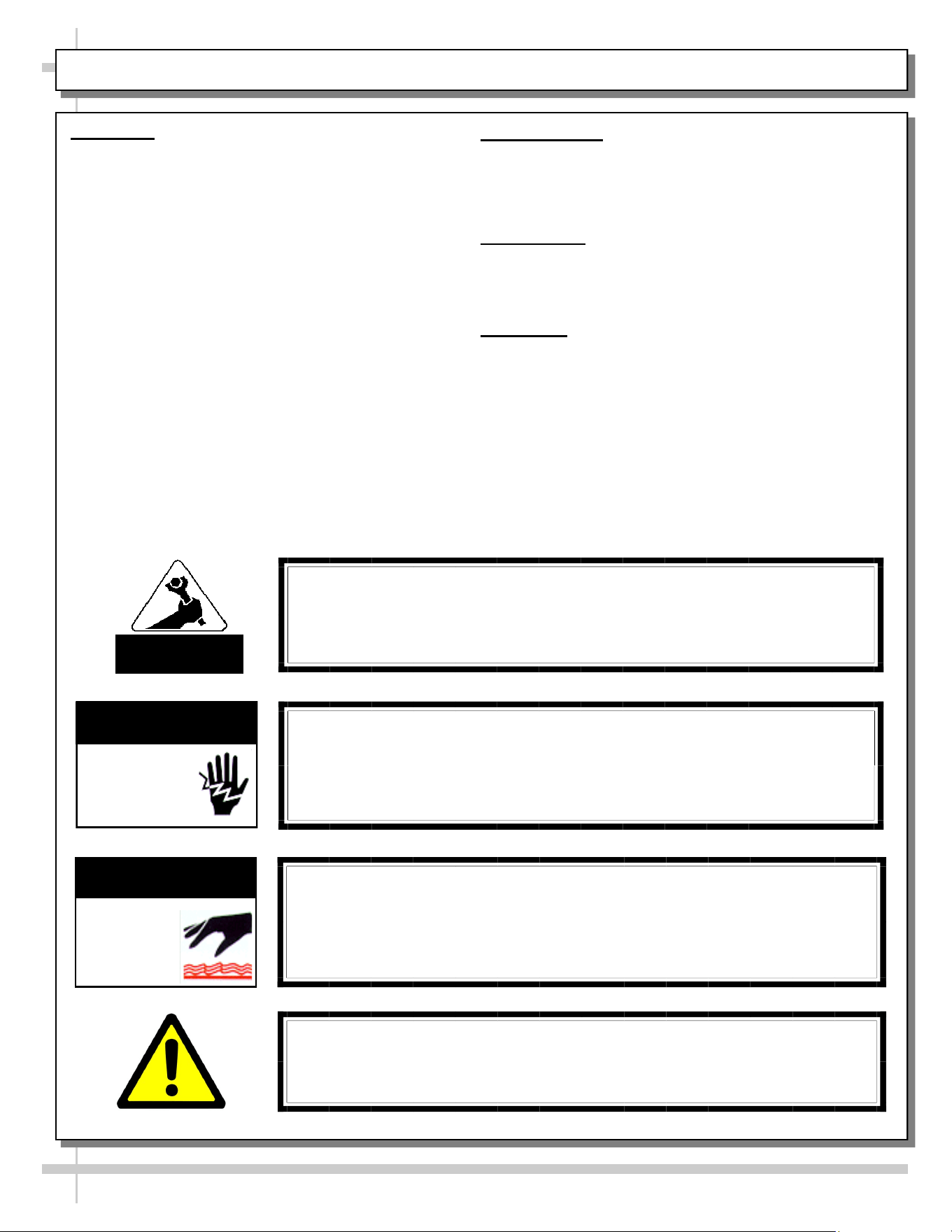
WARNING
Risk of electric shock. Disconnect power before servicing unit.
CAUTION! More than one source of electrical supply may be
employed with units that have separate circuits.
Disconnect ALL ELECTRICAL SOURCES before servicing.
WARNING
ELECTRICAL
HAZARD
OVERVIEW
• These Structural Concepts Reveal® heated cases
are designed to hold pre-heated, perishable,
packaged foods at 140 °F to 180 °F (60 °C to 82 °C).
• Cases should be installed and operated according to
this operating manual’s instructions to insure proper
performance. Improper use will void warranty.
• Product must be pre-heated before placing in
merchandiser. This case is NOT designed to heat
product from cold or ambient conditions.
• All heating elements are thermostat controlled for
individual adjustment.
COMPLIANCE
This equipment MUST be installed in compliance with
all applicable NEC, federal, state and local
electrical and plumbing codes.
THERMOMETER
• Thermometers in equipment reflect internal air
temperature only (not actual food temperature).
• Use probe thermometers to determine actual product
temperatures.
COMPLIANCE
• Performance issues when in violation of applicable
NEC, federal, state and local electrical and plumbing
codes are not covered by warranty. See below.
WARNINGS
• Please read the important warnings in this document
carefully as they can prevent injury or death.
• See next page for PRECAUTIONS.
ATTENTION
CONTRACTORS
WARNING: This product can expose you to chemicals, including
Urethane (Ethyl Carbamate), which are known to the state of
California to cause cancer and birth defects or other reproductive
harm. For more information go to P65Warnings.ca.gov.
WARNING
Decks and shelves may be hot! Disconnect and allow to cool
before cleaning or removing from case.
WARNING
HOT
SURFACE
5
OVERVIEW / DISPLAY TYPE I vs. II / COMPLIANCE / WARNINGS / PRECAUTIONS - PAGE 2 of 2
PRECAUTIONS
• Following are important precautions to prevent damage to unit or merchandise.
• Please read carefully!
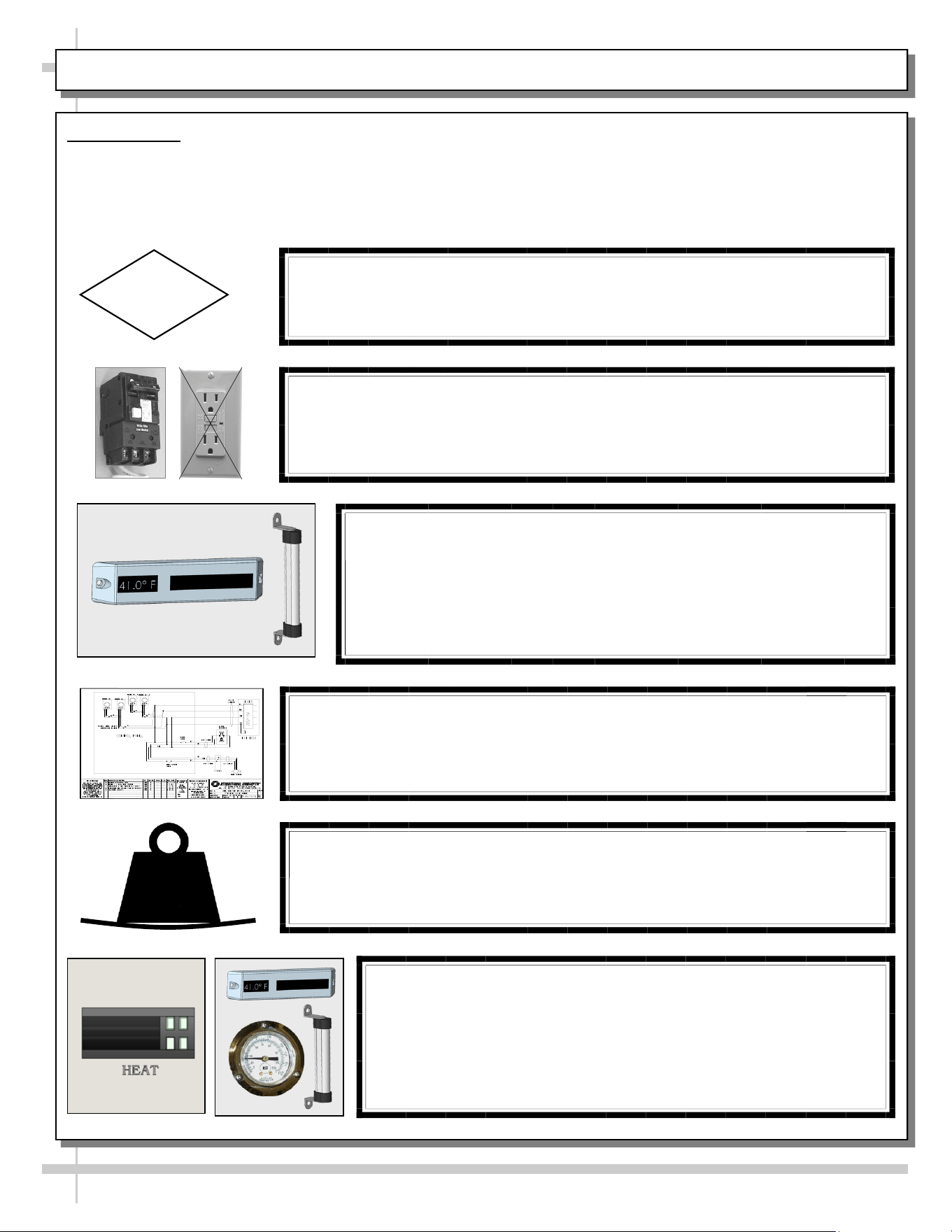
CAUTION! LAMP REPLACEMENT GUIDELINES
LED lamps reflect specific size, shape and overall design.
Any replacements must meet factory specifications.
CAUTION
WIRING DIAGRAM FORMAT & LOCATION
• Each case has its own wiring diagram folded & in its own packet.
• Wiring diagram placement may vary; it may be placed near field
wiring box, raceway, or other related location.
CAUTION!
DO NOT RELY ON THERMOMETERS OR THERMOSTATS
FOR ACTUAL PRODUCT (FOOD) TEMPERATURES.
• Thermometers and thermostats reflect air temperatures ONLY.
• For PRECISE food temperatures, use calibrated food
thermometers ONLY.
CAUTION! GFCI BREAKER USE REQUIREMENT
If N.E.C. (National Electric Code) or your local code
requires GFCI (Ground Fault Circuit Interrupter) protection,
you MUST use a GFCI breaker in lieu of a GFCI receptacle.
CAUTION!
• To prevent sagging or breakage, do not exceed 5 LBS (2.3 KG)
weight load per top glass section (between vertical supports).
• To prevent scratching or marring, do not place ANY items on glass.
5
LBS
CAUTION!
DO NOT RELY ON THERMOMETERS OR THERMOSTATS
FOR ACTUAL PRODUCT (FOOD) TEMPERATURES.
• Thermometers & thermostats reflect air temperature ONLY.
• For ACTUAL food temperatures, use a calibrated food
thermometer.
6
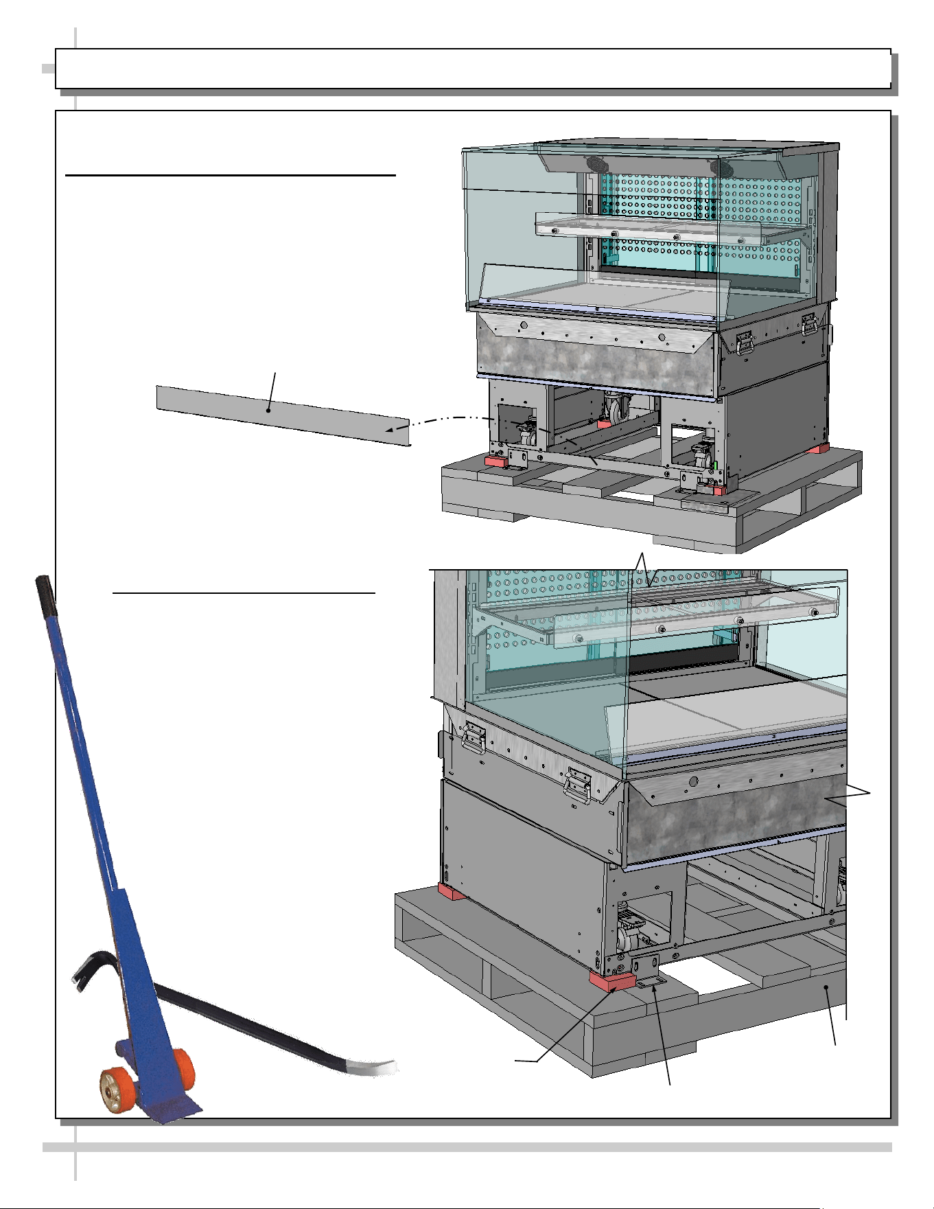
INSTALLATION: TOE-KICK REMOVAL / DISCONNECTING CASE FROM SKID
Skid
Rubber
Shipping
Block
Shipping Bracket
1. Remove Front Toe-Kick From Case
• To prevent damage to case, remove front
toe-kick from case before removing from
Skid.
• Toe-kick is held in place by magnets only.
No screw removal is required.
• Place front toe-kick in secure location
while removing case from Skid.
Front Toe-Kick
2. Disconnect Case From Skid
• Remove screws from shipping
brackets. Remove and discard
shipping brackets from Skid.
• Place J-bar/pry under base frame.
Raise case up from Skid to take
weight off casters.
• With case raised, lower casters all
the way down against Skid (see
next step for detailed instructions on
lowering or raising casters).
• Remove rubber shipping blocks.
7
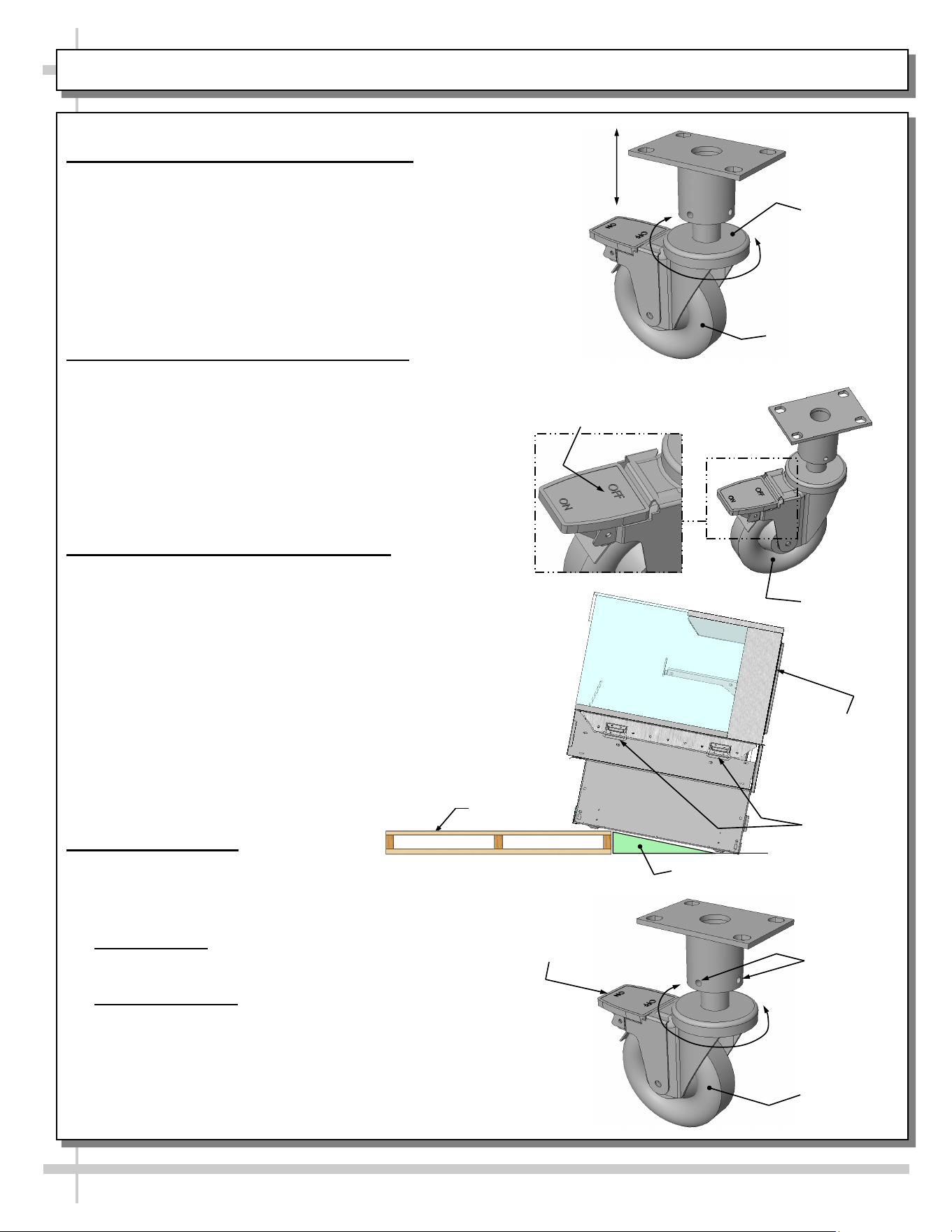
INSTALLATION, CONT’D.: CASTER ADJUSTMENT / LOCK / UNLOCK / CASE REMOVAL FROM SKID
3. Caster Height: Raising and Lowering
• Raise or lower casters (to adjust case height) by
rotating casters’ vertical adjustment rings.
• Rotate vertical adjustment ring clockwise to lower
caster (and increase height of case).
• Rotate vertical adjustment ring counter-clockwise
to raise caster (and decrease height of case).
4. Caster Rolling Capability: Unlocking
• Important! Case is shipped with caster mechanisms
factory set at ON (locked) to prevent case from
rolling.
• Unlock casters by pressing OFF on the caster
mechanism.
• See illustration at right.
5. Carefully Remove Case From Skid
• Check that casters are lowered as far down as they
will go (as instructed in step #4).
• Use handles to carefully slide case to rear of Skid
(see illustration at right).
• Caution! 4 people may be required for this task!
• Carefully lower to floor (using ramp if available).
• Slide Skid from under case as required.
• Maintain support of case at all times or center
of gravity may cause case to fall.
• See illustration at right.
6. Casters: Locking
• After case is at desired position (and height), use level
to check that case is level and plumb.
• Readjust height as needed (as instructed in
step #4).
• Locking Height: After proper height (and
positioning) of case is attained, tighten the two
(2) set screws to lock each caster’s height in place.
• Locking Movement: Then, to prevent casters’ rolling
capability, lock casters by pressing ON atop the “ON”
and “OFF” lever mechanism (shown at right). Case
will now be secured at its new location.
Vertical
Adjustment
Ring
Caster
Caster
Tighten Set
Screws To
Lock Caster
Height In
Place
Press “ON” Lever To
Lock Caster In Place
(And Prevent Casters’
Rolling Capability)
Skid
Support case
while removing
from Skid
Press “OFF” Lever To
Unlock Casters (And
Allow Casters To Roll)
Caster
Handles
Ramp
8
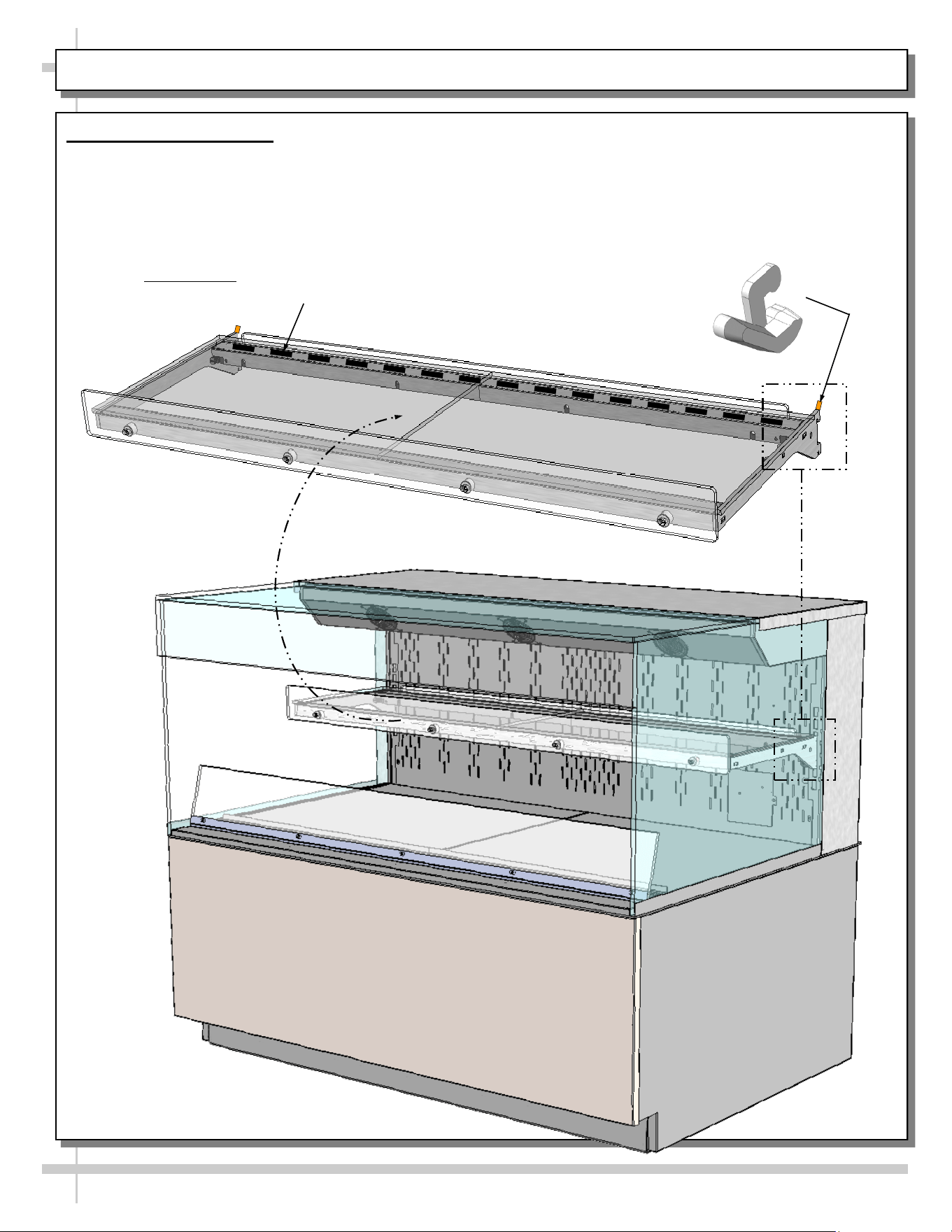
INSTALLATION, CONT’D: SHELVING ASSEMBLIES / SHELVING RETAINER CLIP REMOVAL
7. Shelving Assemblies
• Shelving retainer clips help secure shelves during
shipping
• After case is in place & level (before startup),
you must remove shelving retainer clips.
See illustration below.
• Check that glass shelving is in proper position before
placing product in case
• Shelves may be adjusted vertically or entirely removed
from merchandiser.
• Metal shelving brackets ARE NOT able to be angled.
From Factory: Transparent 2-Sided Tape Holds
Glass To Top Of Rear Shelf Support Rail
Shelving Retainer Clip
(Typ.) Is To Be Removed
After Case Is In Place and
Level (Before Startup)
9
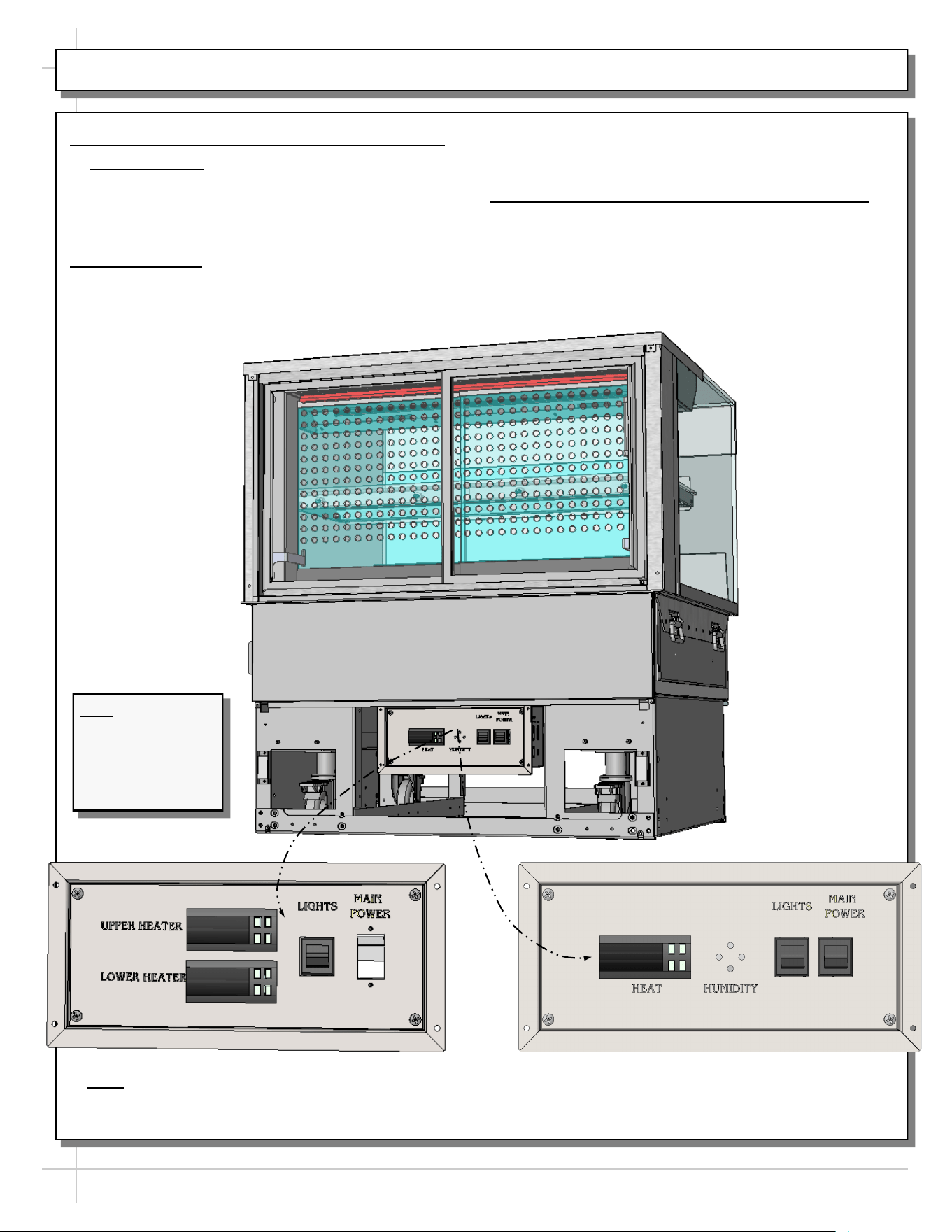
INSTALLATION, CONT’D: PLUG IN UNIT / TURN ON MAIN POWER SWITCH AND LED LIGHTS SWITCH
8. Shelving Retainer Clips To Be Removed
• Important Note: If you have not done so already,
after case is in place and level (before startup),
your must remove shelving retainer clips.
• See previous page for illustration.
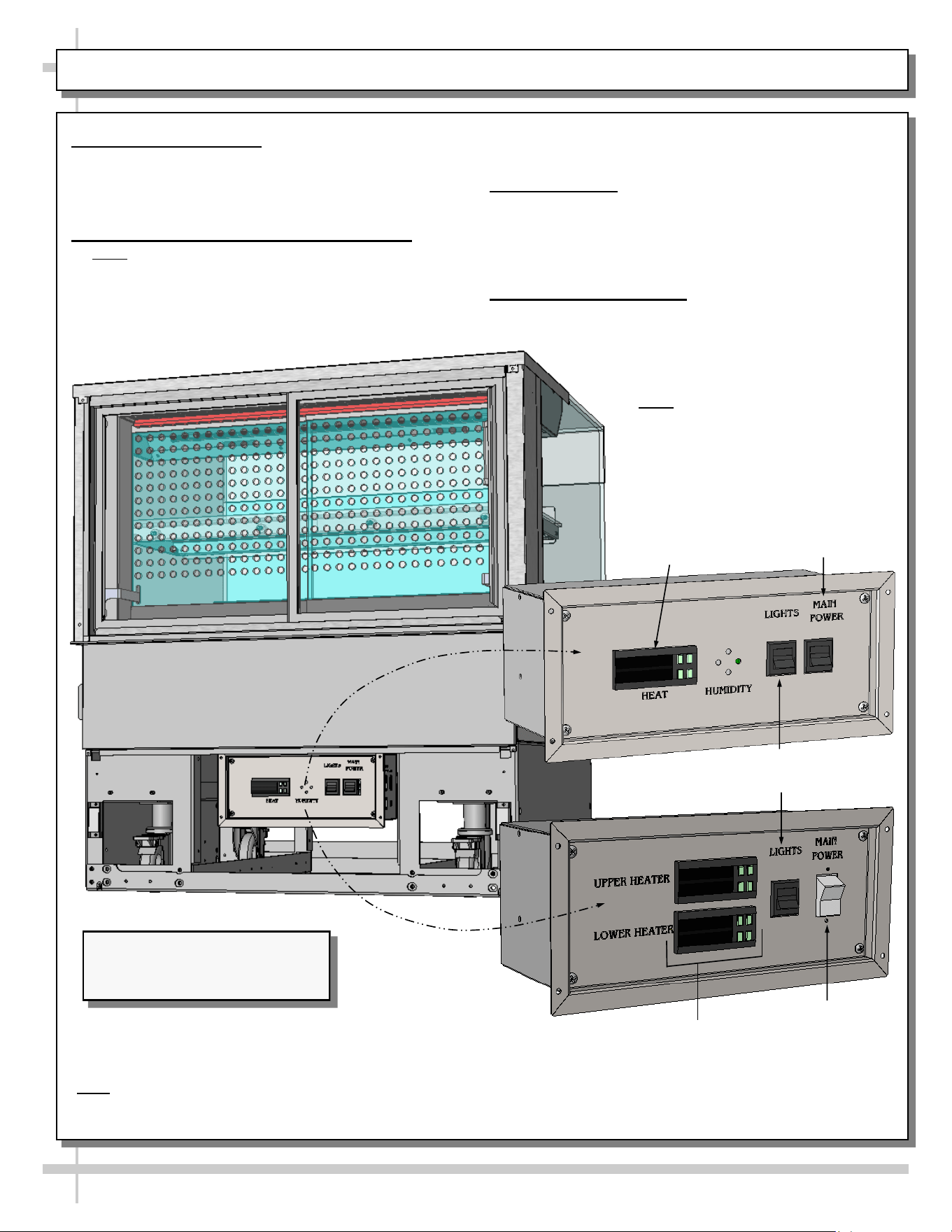
9. Plug Case In
• Check field access box for factory-supplied
power cord.
• Plug case into electrical outlet.
• See enlarged illustration below-right.
10. Main Power Switch / LED Lights Switch
• Main power switch and LED lights switch is
accessible at case rear electrical box.
• Turn on main power switch and LED lights
switch.
• See partially-disassembled illustration below.
- OR -
**
*Note: Only taller units have upper and lower heaters (with two programmable controllers). All others have
only ONE heater (with ONE programmable controller).
**If “HUMIDITY” etching is on faceplate, simply ignore; such markings are not applicable to cases in manual.
*
*
Note: Model Shown
May Not Exactly
Reflect Every
Feature or Option of
Your Particular
Case.
Note: Illustration shown may
not reflect every feature or
option of your particular case.
10
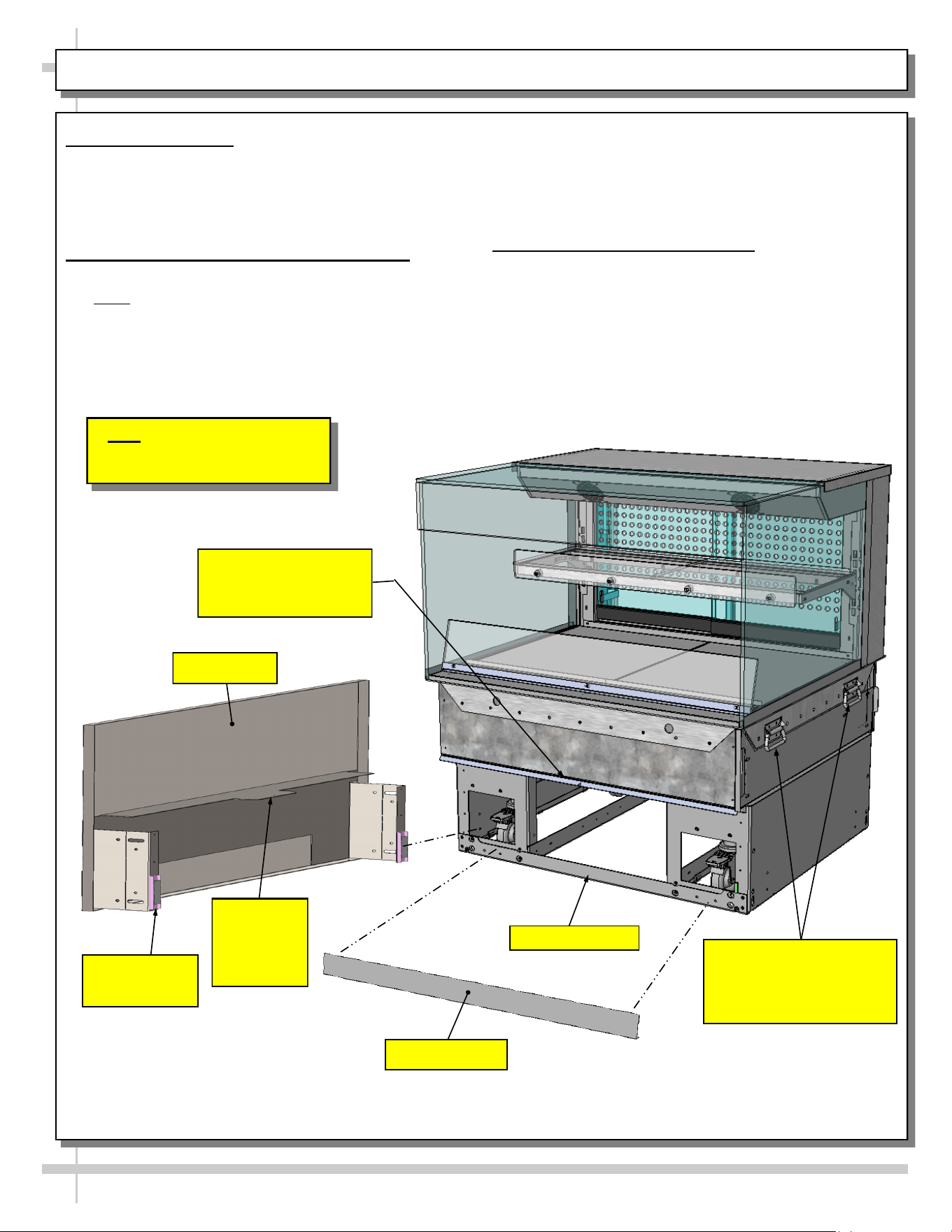
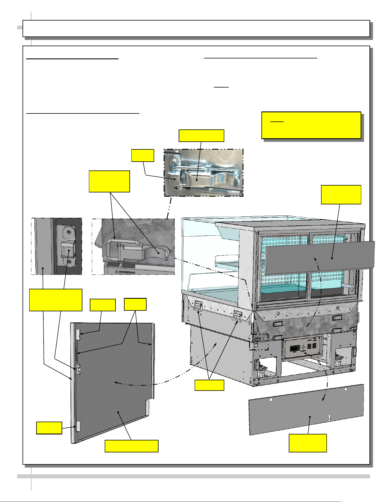
INSTALLATION, CONT’D: ATTACHING FRONT PANEL COMPONENTS
11. Shipping Brace
• Shipping brace keeps case secure during
shipment as well as during positioning in store.
• After case is in position, shipping brace may be
removed from case front (though not required).
12. Attaching Front Panel Components
• Carefully remove components from packaging.
• Note: All front panel components may be attached
to case via magnets (WITHOUT screw
attachments).
• Attach front toe-kick to case (via lower magnets).
• Slide front panel horizontal support bracket into
case’s support slot (line up arrows).
• Then, slide front panel into case until it attaches
to case via lower magnets.
• See illustration below.
13. Handles On Sides of Case
• Handles may remain on case after it has been
moved into position and cladding is attached.
• However, if handles interfere with the placement
of cladding, they may be removed.
>> See Next Page For Instructions on ATTACHING
SIDE PANELS AND REAR PANELS.
Support Slot (For Front
Panel’s Horizontal
Support Bracket)
Shipping Brace
Front Toe-Kick
Front Panel
Horizontal
Support
Bracket
Front Panel
Magnet (Typ.)
Front Panel
Handles (on Both Sides
of Case) May Be
Removed If They Interfere
With Cladding.
11
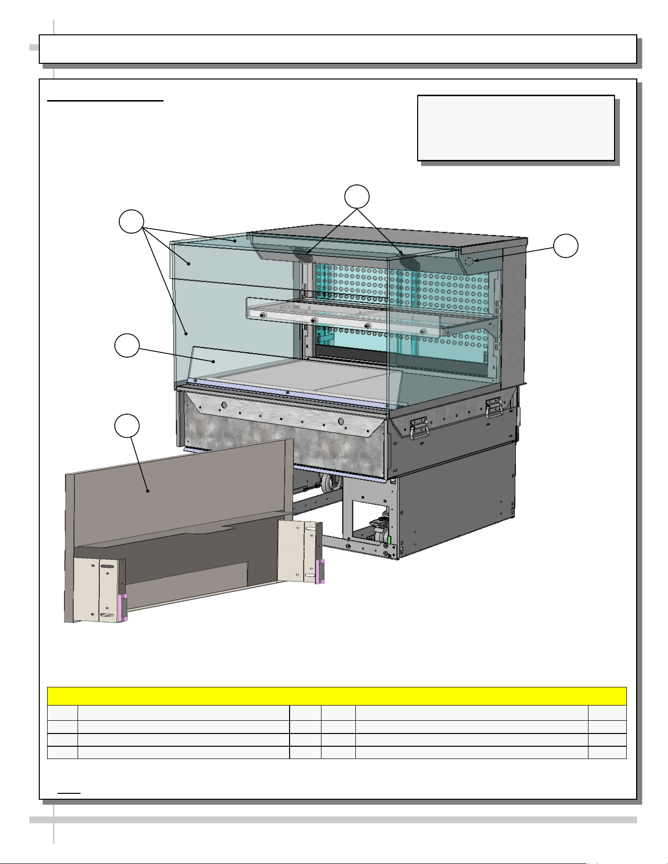
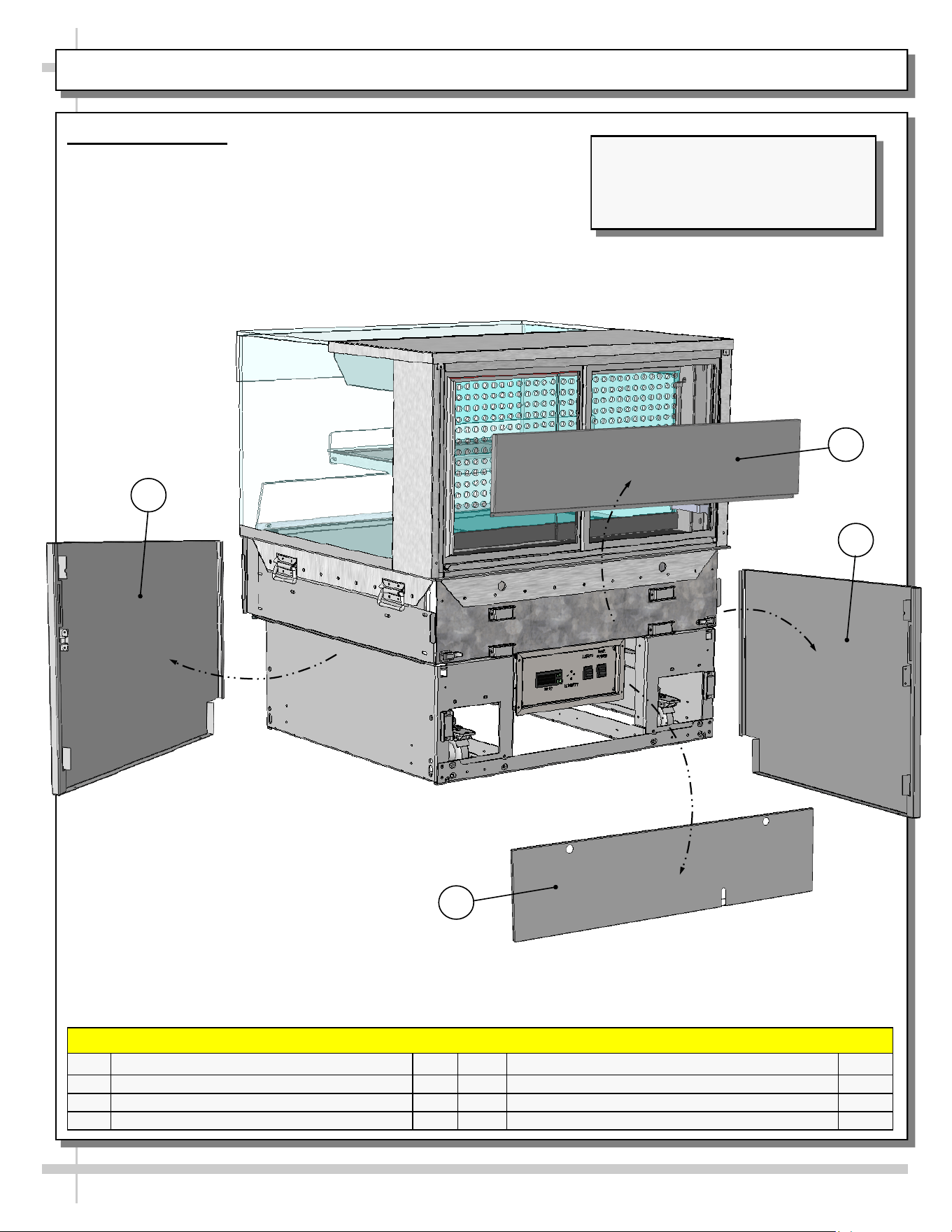
INSTALLATION, CONT’D: ATTACHING SIDE PANELS AND REAR UPPER/LOWER PANELS
14. Attaching Side Panels
• Attach side panels to case using slot/hook
method.
• Use latches at case rear to firmly attach side
panels to case.
• See illustrations below.
15. Attaching Rear Upper Panel
• Place rear upper panel onto care rear.
• Four (4) magnets will hold it firmly in place.
• See illustration below
16. Attaching Rear Lower Panel
• Use finger holes to place rear panel onto lower
rear of case. Magnets will hold it firmly in place.
>> Note: Components may be removed in reverse
order they were shown being attached on this sheet.
Note: Illustration shown may
not reflect every feature or
option of your particular case.
Rear Lower
Panel
Unlocked
Latch (Typ.)
Side Panel (Typ.)
Slots
Side Panel And
Hook (Typ.)
Insert
Handles
Locked Latch
Hook
Insert
Rear Upper
Panel
12
CASE DESIGN & FIELD SERVICE PARTS LIST: CASE FRONT VIEW
1. Case Front View
• Model NR3640HSSV with rear sliding doors is illustrated below.
• Solid back units differ from unit shown.
Model NR3640HSSV Free-Standing
Unit (Shown) May Not Exactly Reflect
Every Feature or Option of Your
Particular Case.
FIELD SERVICE PARTS LIST: CASE FRONT VIEW
P/N COMPONENT NAME AMT P/N COMPONENT NAME AMT
1 UV-BONDED GLASS ASSEMBLY 1 4 AIR DEFLECTOR 1
2 FAN (IN UPPER AIRFLOW SYSTEM)* 5* 5 FRONT PANEL ASSEMBLY 1
3 HEATER ROD** 1
3
2
1
4
5
*Number of fans vary depending upon model.
**Note: Only taller models have a heater rod (accompanied by a separate programmable controller).
13
CASE DESIGN & FIELD SERVICE PARTS LIST, CONT’D: CASE REAR VIEW
2. Case Rear View
• Model NR3640HSSV with rear sliding doors is illustrated below.
• Solid back units differ from unit shown.
FIELD SERVICE PARTS LIST: CASE REAR VIEW
P/N COMPONENT NAME AMT P/N COMPONENT NAME AMT
6 REAR UPPER PANEL 1 9 REAR-LEFT SIDE PANEL 1
7 REAR-RIGHT SIDE PANEL 1
8 REAR LOWER PANEL 1
Model NR3640HSSV Free-Standing
Unit (Shown) May Not Exactly Reflect
Every Feature or Option of Your
Particular Case.
6
7
9
8
14
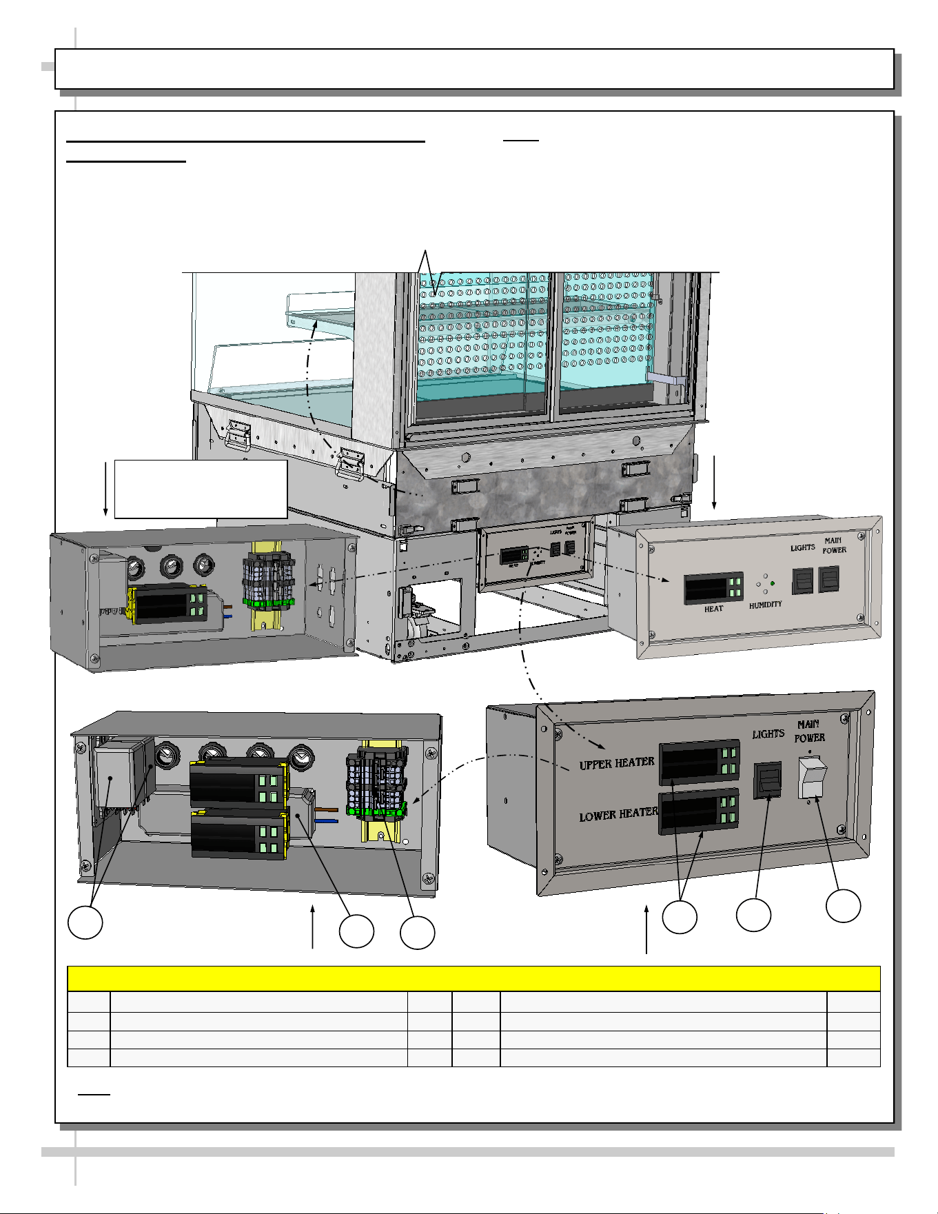
CASE DESIGN & FIELD SERVICE PARTS LIST, CONT’D: ELECTRICAL BOX COMPONENTS
3. Thermostat / LED Driver / Lights / Main
Power Switch
• Remove rear lower panel by lifting up and off; no
screw removal is required.
• Remove 4 screws from the controller/DC driver
box cover to access electrical components.
• Note: Only certified electricians are to access
electrical components in case.
• After accessing controller, return components to
case in reverse order they were removed.
**
Electrical Box With Single
Programmable Controller
(With Faceplate Attached)
FIELD SERVICE PARTS LIST: ELECTRICAL BOX COMPONENTS
P/N COMPONENT NAME AMT P/N COMPONENT NAME AMT
10 RELAYS 2 13 PROGRAMMABLE CONTROLLERS 2*
11 DRIVER 1 14 LIGHTS SWITCH 1
12 TERMINAL STRIP 1 15 MAIN POWER SWITCH 1
Electrical Box With Single
Programmable Controller
(With Faceplate Attached)
Electrical Box With Two
Programmable Controllers
(Faceplate Attached)
10
Electrical Box With Two
Programmable Controllers
(Faceplate Removed)
11
14
15
13
12
- OR -
- OR -
* Note: Only taller models have upper AND lower heaters (requiring two programmable controllers). All others have
only ONE heater (with ONE programmable controller).
15
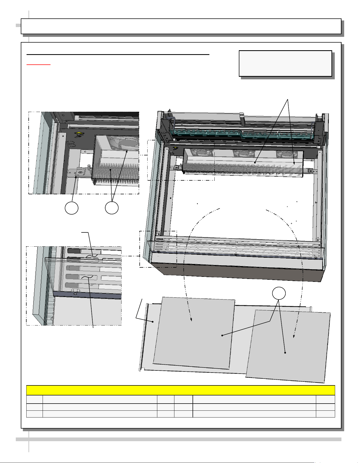
4. Tub Area Access / Heater / Airflow Baffle & Deflector
Caution! Turn main power off before accessing heater components.
• To access tub area (including heater) remove sub-deck and deck pans.
No screw removal is required.
• After cleaning or servicing, return sub-deck & deck pans to case.
• Restore power to case.
CASE DESIGN & FIELD SERVICE PARTS LIST, CONT’D: HEATER / DECKS / BAFFLE / AIR DEFLECTOR
Model Shown May Not Exactly
Reflect Every Feature or Option
of Your Particular Case.
*Number may vary depending upon model.
Air Discharge
Baffle
FIELD SERVICE PARTS LIST: HEATER / DECKS / BAFFLE / AIR DEFLECTOR
P/N COMPONENT NAME AMT P/N COMPONENT NAME AMT
16
HEATER STRIP 2
18
DECK PAN 2
17 HEATER FAN (HOUSING SHOWN X-PARENT) 3*
Sub-Deck
--- Case Rear ---
--- Case Front ---
Air
Deflector
Heater Fan Assembly
(Shown Transparent)
16
17
18
16
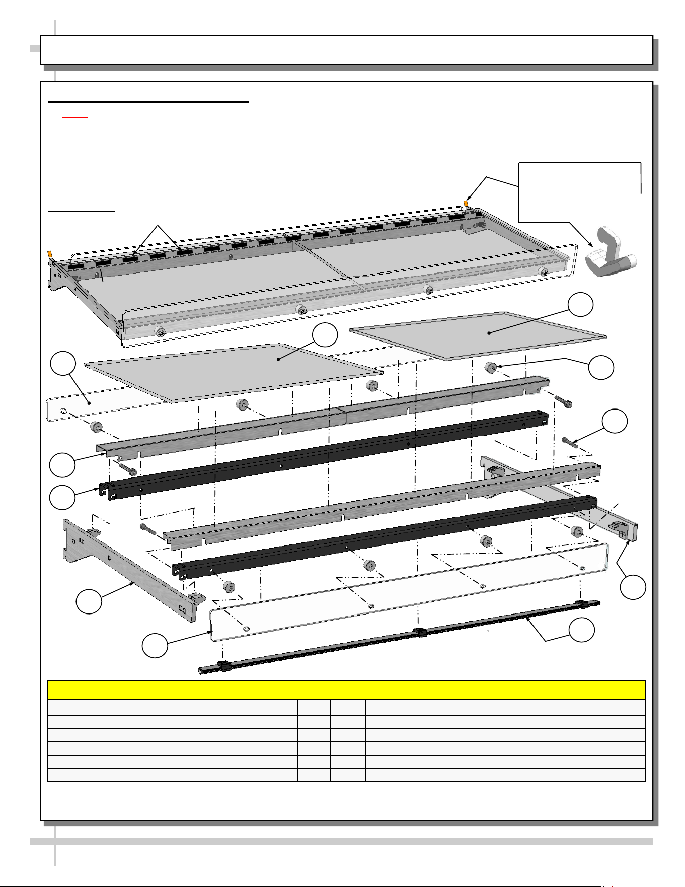
CASE DESIGN & FIELD SERVICE PARTS LIST, CONT’D: SHELVING ASSEMBLY COMPONENTS
5. Shelf Assembly Components
• Note: After case is in place & level (before startup),
remove shelfing retainer clips (sample clip shown
below-right).
• Check that glass shelving is in proper position before
placing product in case
• Shelves may be adjusted vertically or entirely removed
from merchandiser.
• Metal shelving brackets ARE NOT able to be angled.
They are at a fixed 90° position.
• These components comprise EACH shelf assembly.
FIELD SERVICE PARTS LIST: SHELVING ASSEMBLY COMPONENTS
P/N COMPONENT NAME AMT P/N COMPONENT NAME AMT
19 GLASS, LEFT/RIGHT HAND 2 24 SHELF GUARD, FRONT POLYCARBONATE* 1
20
SHELF GUARD, REAR POLYCARBONATE* 1
25
LIGHT, LED 1
21
SHELF SUPPORT RAIL, OUTER** 2 26 BRACKET, RIGHT HAND 1
22
SHELF SUPPORT RAIL, INNER 2 27 THUMB SCREW, SHELF SUPPORTS 4
23 BRACKET, LEFT HAND 2 28 BUMPER STAND 8
* Polycarbonate does NOT need to be removed to remove shelf assemblies from case.
** Assembled with shelf support rail, inner (item #22) and thumb screw (item #27) before leaving the factory.
27
1
25
20
28
From Factory: Transparent 2-Sided Tape Holds
Glass To Top Of Rear Shelf Support Rail
Shelving Retainer Clips
Are To Be Removed
After Case Is In Place &
Level (Before Startup)
19
24
23
22
21
26
17
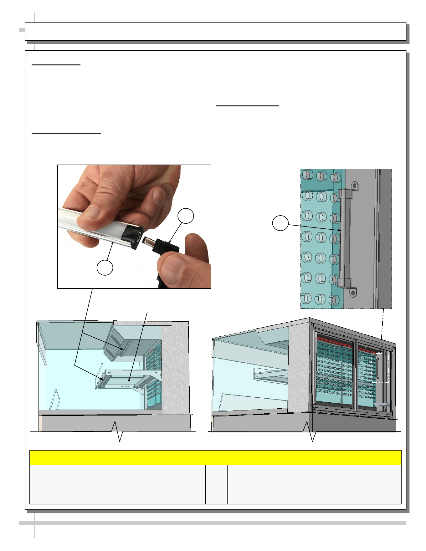
CASE DESIGN & FIELD SERVICE PARTS LIST, CONT’D: LED LIGHT / PLUG / THERMOMETER
Shelf
FIELD SERVICE PARTS LIST: LED LIGHTS / PLUGS / THERMOMETER
P/N COMPONENT NAME AMT P/N COMPONENT NAME AMT
29
LED LIGHT (ALSO CALLED OUT
ON PREVIOUS PAGE)
1 31 THERMOMETER 1
30 PLUG, LED LIGHT 1
29
30
31
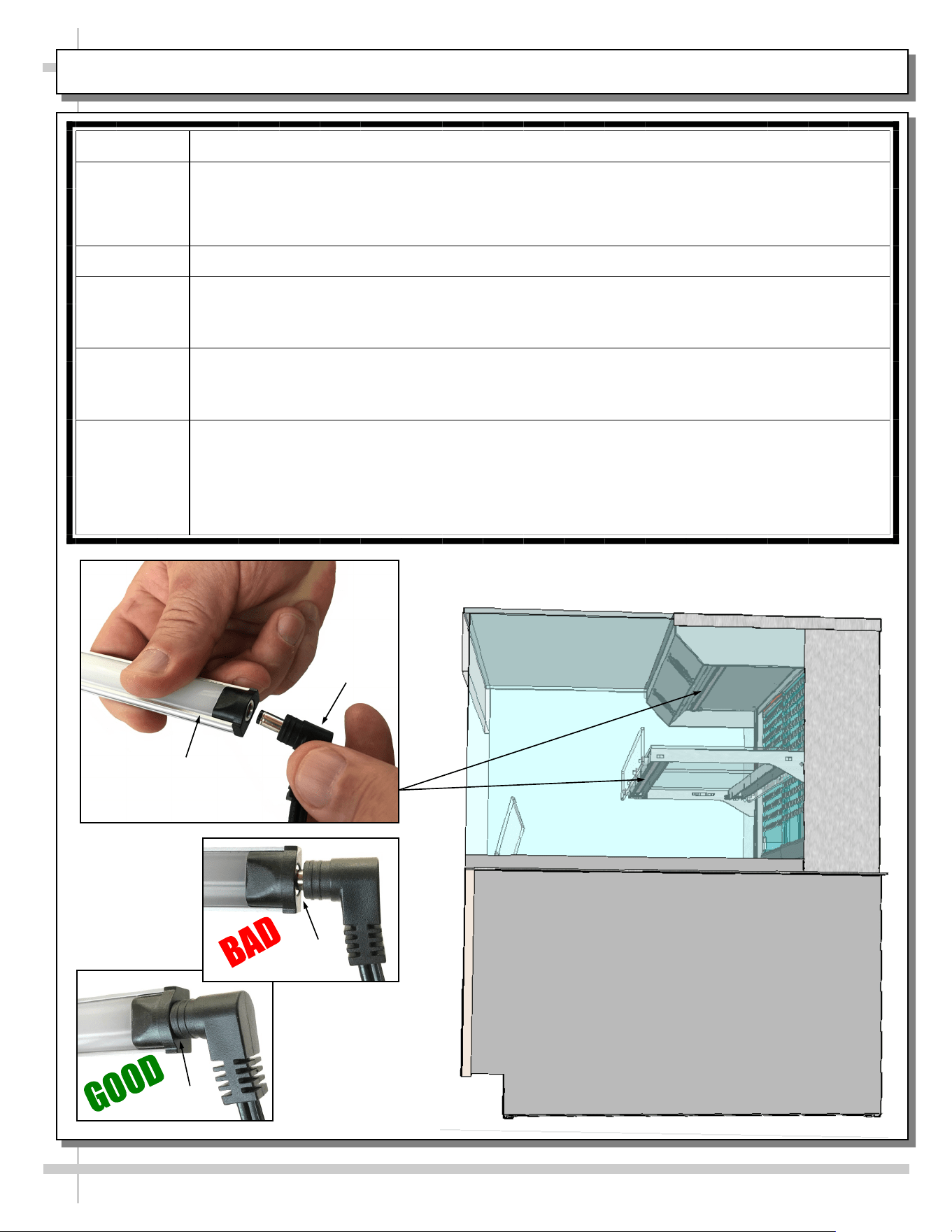
6. LED Light
• LED lights are located at both header and
shelving of case (as shown below).
• Check that ALL of the light plugs are properly
connected to the LED light.
• See TROUBLESHOOTING section in manual
if LED lights malfunction.
7. LED Light Plug
• LED lights are located at both header and
shelving of case (as shown below).
• Check that ALL plugs are properly connected to
the LED lights.
• Plug must be inserted ALL THE WAY into the
LED light orifice (with no gap) to work properly.
8. Thermometer
• Thermometer provides air temperature of
heated section of case.
• Thermometers DOES NOT provide actual food
temperature.
• Use probe thermometer to determine actual
product temperatures.
18
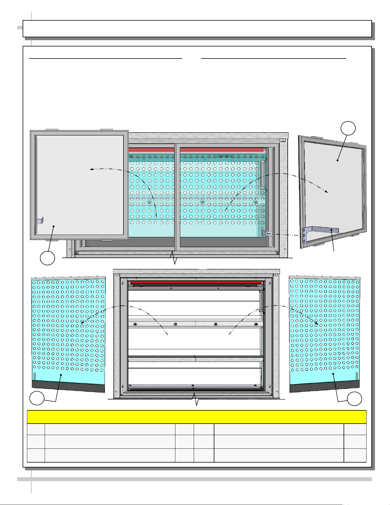
CASE DESIGN & FIELD SERVICE PARTS LIST, CONT’D: REAR PIKE DOORS / PERF. PLENUM DOORS
9. Rear Sliding Pike Doors (With Brackets)
• Rear sliding pike doors also control perforated
plenum via inner bracket (as illustrated below).
• To remove rear sliding doors, move them toward
center of case.
• Individually lift each door up toward the top of the
case; pivot the bottom of the door out.
• Return doors to case in reverse order they were
removed.
Inner Bracket To Control
Inner Perforated Plenum
FIELD SERVICE PARTS LIST: REAR SLIDING PIKE DOORS / PERFORATED PLENUM SLIDING DOORS
P/N COMPONENT NAME AMT P/N COMPONENT NAME AMT
32
PIKE DOOR, OUTER WITH INNER BRACKET,
REAR-LEFT
1
34
PERFORATED SLIDING DOOR, INNER 2
33
PIKE DOOR, OUTER WITH INNER BRACKET,
REAR-RIGHT
1
10. Rear Sliding Inner Perforated Doors
• Rear sliding inner perforated doors are shown
below.
• To remove, slide toward center of case.
• Individually lift each door up toward the top of the
case; pivot the bottom of the door out.
• Return perforated doors to case in reverse order
they were removed.
32
34
33
34
19
CASE STARTUP / HEATER SETTINGS / LIGHTS SWITCH / SHUTTING DOWN CASE
• If adjusting heater settings, allow 20 minutes at new
settings for temperature to affect product.
3. Light Switch
• Control panel (at case rear) is accessible after
removal of lower-rear panel.
• Turn lights switch “ON” to turn on lights.
• All LED lights will come on at the same time.
4. Shutting Down Case
• Remove all product from case.
• Turn main power switch to “OFF” position.
• Caution! Deck and shelving are
hot. Allow case to cool for 45
minutes before cleaning.
• Note: When main power is turned
back on, you do NOT need to
re-enter settings. Temperatures will
revert back to your LATEST
SETTINGS before shutdown.
1. Main Power Switch
• Control panel (at case rear) is accessible after
removal of lower-rear panel.
• Turn main power switch “ON” to energize case.
2. Heating Up Case / Adjusting Settings
• Note: Cases are designed to MAINTAIN product
temperatures – NOT heat up product! Do not place
product that is cold or ambient temperature in case.
• Before placing pre-heated food in case, allow
1 1/2 hours (90-minutes) for case to achieve its
desired temperature.
Model Shown May Not Exactly
Reflect Every Feature or Option
of Your Particular Case.
**
- OR -
Programmable
Controller
Lights
Switches
Main Power
Switch
Programmable
Controllers*
Main Power
Switch
*Note: Only taller units have upper and lower heaters (with two programmable controllers). All others have only ONE
heater (with ONE programmable controller).
**If “HUMIDITY” etching is on faceplate, simply ignore; such markings are not applicable to cases in user manual.
20
START-UP AND OPERATION, CONTINUED: LOAD LIMITS
20
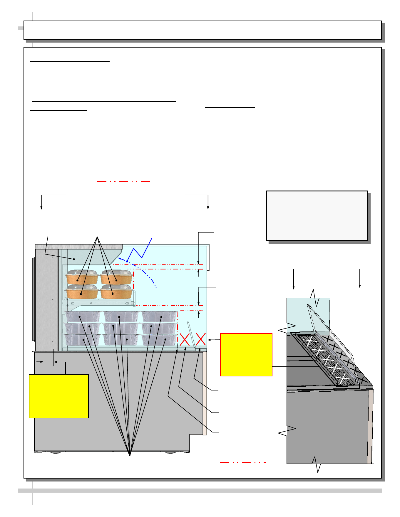
PRODUCT PLACEMENT / AIRFLOW CONSIDERATION / LOAD LINES
• See illustration below.
• Caution! For discharged air to reach the return air
grille, you must not block front OR rear grilles with
product.
• Do not place product on front ledge of case.
3. Load Lines
• Load lines represent the limit that product can be
place (either horizontally or vertically) and/or
stacked in case.
• Keep product at or under load lines to assure that
heated airflow is properly cycled from air diffuser
through return air grille.
• Proper product placement will maintain
acceptable product temperature.
• See illustration below.
1. Product Placement
• Product can be placed on decking or steps
(risers) within the service display area.
• A wide range of product may be displayed.
2. Air Diffuser Grille & Return Air Grille
Considerations
• Proper airflow is critical to maintain proper
product temperature.
• Proper product placement will allow discharged
air to flow over (and around) product to the
return air grille (at case rear) AS WELL AS the
upper airflow circulation system. See illustration
below.
Angled View Of
Discharge Air Grille
Load Lines
1” Minimum
Load Line
1” Minimum
Load Line
Model NR3640HSSV (Shown)
May Not Exactly Reflect Every
Feature or Option of Your
Particular Case. However,
General Airflow Consideration
and Load Line Guidelines Apply.
Caution!
2” Air Return
Grille At Rear
Inner.
Do Not Block!
Model NR3640HSSV Shown Below
Load Lines
Caution!
Do Not Place
Product On
Discharge Air
Grille or Ledge
Product Stop
Sample
Product (Typ.)
Discharge Air
Grille
Ledge
Upper Airflow
Circulation
System
Sample
Product (Typ.)
Airflow Direction of
Upper Airflow
Circulation System
21
CLEANING SCHEDULE (TO BE PERFORMED BY STORE PERSONNEL)
FREQ. INSTRUCTIONS
Daily Glass Surfaces (Including Shelves): Clean glass surfaces and shelves with household or
commercial glass cleaner.
Daily Rear Sliding Door Exterior Glass: Clean with household or commercial glass cleaner. Clean out
rear door track with moist cloth.
Daily End Panels, Front Panel, Toe-Kick, etc.: Wipe off all surfaces with warm water and mild soap
solution and non-abrasive cloth.
Daily Decks: Wipe off decks with moist cloth dipped in mild soap and water solution.
Daily Stainless Steel Surfaces:
• Wash with a solution of hand dishwashing liquid detergent and water or a solution of baking
soda and water. Rinse and polish dry with paper towel or soft cloth.
• Never use scouring powders or steel wool as they will scratch stainless steel.
• Brighten by polishing with a cloth dipped in vinegar or in ammonia; sprinkle baking soda on
sponge and rub gently; rinse. Polish dry with paper towel.
• Remove streaks or heat stains from stainless steel by rubbing with club soda.
Quarterly Under Case Cleaning:
• Remove front and/or lower rear panel.
• Use broom or vacuum to remove all dust, dirt, food particles or residue from underside of case.
• For units with optional humidification system, check overflow; if it needs to be emptied or
cleaned, do so.
• Replace front and/or lower rear panel after cleaning.
22
FREQ. INSTRUCTIONS
Quarterly
Tub Area:
• Caution! Turn off power to case. Allow case to cool for 45 minutes before proceeding.
• Remove sub-deck and deck pans.
• Wipe down tub area.
• Return subdeck and deck pans to case.
• Restore power to case.
WARNING! TURN OFF CASE BEFORE PERFORMING PREVENTIVE MAINTENANCE!
PREVENTIVE MAINTENANCE (TO BE PERFORMED BY TRAINED SERVICE PROVIDER)
23
TROUBLESHOOTING (TO BE PERFORMED BY STORE PERSONNEL) - PAGE 1 OF 2
CONDITION TROUBLESHOOTING
Fan Noise Is
Excessive
Call service provider.
Case is Not
Holding Proper
Temperature
If a large amount of cool (or ambient) product was added to the case, it will take time
for the temperature to adjust. Product must be pre-heated before placing in case.
• Check air return grilles (area at front of decking) for obstructions.
• DO NOT set product on air grilles as this will prevent proper airflow!
• See PRODUCT PLACEMENT / AIRFLOW CONSIDERATION / LOAD LINES
section in manual for product placement guidelines.
Check that the case is not in the sun or directly under HVAC/air conditioner ducts.
See OVERVIEW / DISPLAY TYPE I vs. II / COMPLIANCE / WARNINGS /
PRECAUTIONS section in this manual for specifics.
If case still is not holding proper temperature, call service provider.
Check all fans to confirm that all are operating.
24
TROUBLESHOOTING (TO BE PERFORMED BY STORE PERSONNEL) - PAGE 2 OF 2
CONDITION TROUBLESHOOTING
Case Lights
Not Working
Check that light switch is in the ON position.
• See INSTALLATION, CONT’D: PLUG IN UNIT / TURN ON MAIN POWER SWITCH
AND LED LIGHT SWITCH section in manual for switch location (regardless of case
design).
If case is not hard-wired, check that power cord is properly connected to wall outlet.
Check that ALL of the light plugs are properly connected to the LED light.
• Plug must be inserted ALL THE WAY into the LED light orifice (with no gap).
• See illustrations below-left.
Power may not be reaching the case.
• Contact store management to have trained service provider perform troubleshooting.
• Troubleshooting to be performed by trained service providers only is on next page.
If case light still do not come on, it may need to be replaced.
• Contact Structural Concepts’ Technical Service Department for replacement light
(see TECHNICAL SERVICE section of this manual for contact information).
• To replace, disconnect plug from existing LED light. Disconnect LED light from its
brackets. Replace with new LED light. Insert plug ALL THE WAY into LED light orifice.
No Gap
Gap
LED Light
Plug
25
CONDITION TROUBLESHOOTING
Fans Emit
Excessive Noise
Check that the case is aligned, level and plumb.
Check axial fans for cleanliness.
Check that fan motors are securely mounted in brackets.
Check that nothing is preventing blade rotation.
Check that the fan shroud is properly secured.
Fans Are Not
Working
Check that the MAIN power switch is on.
Check that fans are plugged.
Check for foreign material obstructing fan performance.
Check that fan blades freely rotate within fan shrouds
Check that power is going to fans
Check that fan wiring is connected on terminal blocks.
System Not
Operating
Check that the utility power is on.
Check that the MAIN power switch is on.
Check the circuit breaker box for tripped circuits.
TROUBLESHOOTING (TO BE PERFORMED BY TRAINED SERVICE PROVIDERS ONLY), PAGE 1 OF 2
26
CONDITION TROUBLESHOOTING
Case Lights Are
Not Working
See TROUBLESHOOTING (TO BE PERFORMED BY STORE PERSONNEL)
section in manual for most common troubleshooting solutions.
Check power.
• If power is not supplied to the case, facility may have faulty power distribution.
• If power is supplied to the case but lights are not energized, case’s power supply
may be faulty.
Case Is Not
Holding
Temperature
If a large amount of product was added to the case, it will take time for the
temperature to adjust.
Check that case is not in sun or near a heat or air-conditioning vent.
Digital Control
Display Is Blank
Check that the MAIN power switch is on.
Check the circuit breaker box for tripped circuits.
System Is Not
Operating
Check that the utility power is on.
Check that the MAIN power switch is on.
Check the circuit breaker box for tripped circuits.
TROUBLESHOOTING (TO BE PERFORMED BY TRAINED SERVICE PROVIDERS ONLY), PAGE 2 OF 2
27
SERIAL LABEL LOCATION & INFO LISTED / TECH INFO & SERVICE - AMBIENT/HEATED CASES ONLY
--- Sample Serial Label For Ambient/Heated Cases ---
MODEL NRS3648RXV-SAMPLE
SERIAL NO. 12345X30DZ098765
888 E. Porter Rd - Muskegon, MI 49441
3048256
Conforms to UL Std. 65
CERTIFIED TO CAN/CSA
STD C22.2 NO 120
120 VOLTS 60HZ
FOR PARTS OR SERVICE CALL
STRUCTURAL CONCEPTS
AT 1-800-433-9489
SINGLE PHASE 1.84 AMPS
Serial Label Location & Information Listed /
Technical Information & Service
• Serial labels are affixed at a wide range of places
(on the header, at case rear, behind panels or
toe-kicks, on electrical boxes, etc.).
• Serial labels contain electrical information as well
as regulatory standards to which the case
conforms.
• Sample serial label shown below.
• For additional technical information and service, see
the TECHNICAL SERVICE page in this manual for
instructions on contacting Structural Concepts’
Technical Service Department.
Sample QR Code
SCAN FOR PRODUCT LITERATURE
Reveal
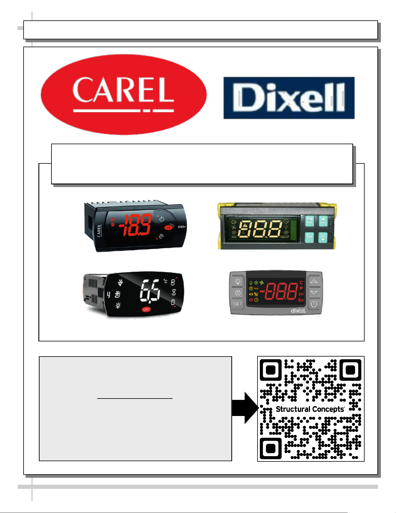
PROGRAMMABLE CONTROLLER (SELECT, CLICK ON OR SCAN QR CODE FOR INFORMATION)
28
Carel® iJF Platform
Carel® PJEZ Platform
Carel® ir33 Platform
Dixell® XM670K-XM679K Platform
To Access Information About The Programmable
Controller That Is Used On Your Case,
Follow These Instructions:
> If Viewing This Document on Smart Phone, Tablet
or Computer, Select/Click On The QR Code at Right.
> If Viewing This Document In Print (Hard Copy),
Scan The QR Code at Right With Your Smart Phone
or Tablet.
Determine Which Programmable Controller Is On Your Case (Controllers
That Are Commonly Used By Structural Concepts Are Shown Below).
Your Particular Programmable Controller May Differ.
STRUCTURAL CONCEPTS TECHNICAL SERVICE CONTACT INFORMATION & LIMITED WARRANTY
29
TECH SERVICE/WARRANTY CONTACT INFO:
1 (800) 433-9490 / EXTENSION 1
DAYS/HOURS AVAILABLE:
MONDAY - FRIDAY (CLOSED HOLIDAYS)
8:00 a.m. TO 5:00 p.m. EST
YOU MUST HAVE THE FOLLOWING INFO AVAILABLE
BEFORE CONTACTING STRUCTURAL CONCEPTS:
SERIAL NO. / MODEL NO. / STORE NO. / STORE
ADDRESS / DETAILS (PHOTOS, LEAK LOCATIONS,
DAMAGE, STORE’S AMBIENT CONDITIONS, ETC.)
To Access The Limited Warranty To Your
Case, Follow These Instructions:
> If Viewing This Document on Smart Phone,
Tablet or Computer, Select/Click On The QR
Code at Right.
> If Viewing This Document In Print (Hard
Copy), Scan The QR Code at Right With Your
Smart Phone or Tablet.