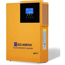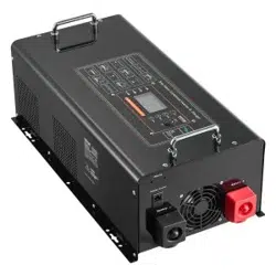
����W ��V
MANUAL
Wave Inverter Charger
Inverter
Version: 1.0
SUPPORT
If you are experiencing technical problems and cannot find
a solution in this manual,please contact ECO-WORTHY for
further assistance.
·Call:1-866 939 8222(US&CA)
+44 7553 406988(UK)
+49 6175 6514 999(DE)
·Web://www.eco-worthy.com/
·E-mail: customer.service@eco-worthy.com
12V / 3000W / 100A
INVERTER CHARGER
PURE SINE WAVE
OUTPUT

Catalogue:
Ⅰ. General Information
Ⅱ. Introduction
Ⅲ. Packing List
Ⅳ. Product Description
Ⅴ. Installation
Ⅵ. Unit Operation
Ⅶ. Troubleshooting
Ⅷ. Specification
Ⅸ. Warranty
VIII. Technical Support
.................................................�
..............................................................�
...............................................................�
..................................................�
..............................................................��
........................................................��
.....................................................��
............................................................��
..................................................................��
.................................................��

Purpose
This manual describes the assembly, installation, operation and trou-
bleshooting of this unit. Please read this manual carefully before
installation and operation.
Scope
The manual provides safety and operating manual lines as well as
information on installing and configuring the inverter-charger. It also
provides information about troubleshooting the unit. It does not
provide details about particular brands of batteries. You need to
consult individual battery manufacturers for this information.
Please Keep This Manual For Future Reference
For safe and optimum performance, the Inverter-Charger must be
used properly. Carefully read and follow all instructions and guide-
lines in this manual and give special attention to the CAUTION and
WARNING statements.
Disclaimer
While every precaution has been taken to ensure the accuracy of the
contents of this guide, we assume no responsibility for any errors or
omissions. Eco-worthy reserves the rights to change specifications
and product functionality without notice.
Important
Please be sure to read and save the entire manual before using your
Sine wave Inverter-Charger. Misuse may result in damage to the unit
and/or cause serious injury. Read manual in its entirely before using
the unit and save manual for future reference.
I.General Information
-�-
Symbols
Definition
Indicates the danger of electric shock. If not avoided, it would
cause casualities.
Indicates a potentially dangerous condition which could result in
injury or death.
Indicates important information or warnings related to concepts
talked about in the text.
Indicates more information is available in other documents relating
to the subject and reader.
Indicates important steps or tips for optimal performance.
-�-
IMPORTANT SAFETY INFORMATION
This section contains important safety information for the Sine wave
Inverter Charger. Before using the unit, please read all instructions
and cautionary markings provided with the unit, and all appropriate
sections of this guide.
The Sine wave Inverter-Charger contains no user-serviceable parts.
See Warranty section for how to handle product issues.
* Do not cover or obstruct any vent openings or install it in a
zero-clearance compartment.
* When working with electrical equipment or lead-acid batteries,
please arrange someone nearby in case of an emergency.
* Study and follow all the battery manufacturer's specific precautions
when installing, using and servicing the battery connected to the
inverter.
* Wear eye protection and gloves.
* Avoid touching your eyes while using this unit.
* Keep fresh water and soap on hand if battery acid comes in contact
with eyes. If it occurs, clean right away with soap and water at least ��
minutes and then seek medical attention.
* Batteries will produce explosive gases. DO NOT smoke or have an
open spark or fire near the system.
* Keep unit away from moist or damp areas.
* Avoid dropping any metal tool or object on the battery. Doing so
may create a spark or short circuit which goes through the battery or
another electrical tool that may create an explosion.
* Avoid moisture. Never expose unit to snow, water, etc.
* The unit provides high voltage AC. Please treat the AC output socket
the same as regular wall AC sockets at home.
-�-
DANGER!
Fire & or Chemical Burn Hazard
WARNING!
Shock Hazard, Keep Away From Children !
DANGER!
Failure to follow these instructions can result in death or serious
injury.
-�-
* DO NOT install the unit near flammable fumes or gases (such as
propane tanks or large engines).
* AVOID covering the vent openings. Always operate unit in an open
area.
*Prolonged exposure to high heat or freezing temperatures will
decrease its lifespan.
* DO NOT connect AC power sources like utility power or generator to
the AC output of the unit. It will damage the unit and may cause fire.
Feeding AC to the AC output of the unit is not covered by warranty.
* The ��V DC unit is designed for ��V House Battery System only. Use
on a higher house battery system will damage the unit and lead to
explosion.
* The ��V DC unit is designed for ��V House Battery System only. Use
on a lower house battery system will damage the unit and lead to
explosion.
* DO NOT use in connection with life support systems or other medi-
cal equipment or devices.
FCC and CE EMC INFORMATION
This equipment has been tested and found to comply with the limits
for a Class B digital device, pursuant to part �� of the FCC Rules (for
���V models) and comply with the CE EMC Standard on ���V models.
These limits are designed to provide reasonable protection against
harmful interference in the residential installation. This equipment
generates, uses, and can radiate radio frequency energy. If it is not
installed and used in accordance with the instructions, it may cause
harmful interference to radio communications. However, there is no
guarantee that interference will not occur in a particular installation.
If this equipment does cause harmful interference to radio or televi-
sion reception, it can be determined by turning the equipment off
and on. The user is encouraged to correct the interference by one or
more of the following measures:
WARNING!
Explosion Hazard !
LIMITATIONS ON USE
���V Series
Thank you for purchasing our Sine wave inverter-Charger. With our
state of the art, easy to use design, this product will offer you reliable
service by providing True Sine wave AC power for your home, cabin,
boat, RV or trailer and recharge your battery automatically when utility
AC is available. The Sine wave Inverter-Charger can run many AC-pow-
ered appliances when you need AC power anywhere. The multi-stage
battery charger will charge different types of batteries. The built-in
transfer switch will automatically switch the load to the battery power
when the utility power is interrupted.
This manual will explain how to use this unit safely and effectively.
Please read and following these instructions and precautions carefully.
* Re-orient or relocate the receiving antenna.
* Increase the separation between the equipment and the receiver.
* Consult the dealer or an experienced radio/TV technician for help.
II.Introduction
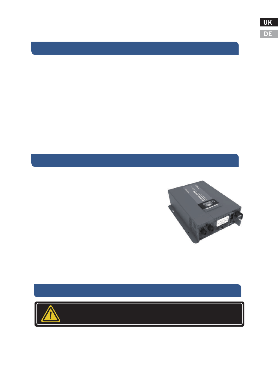
The Sine wave Inverter-Charger includes the
items listed below.
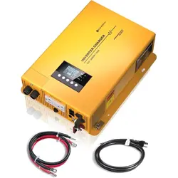
* Inverter-Charger base unit
* Communication Input Cable: with Ameri-
can standard plug, ��AWG; �m
* Battery Connection Cable: �/� AWG; �.�m
* User Manual
It is recommended that all wiring be done by a certified technician or
electrician to ensure adherence to the applicable electrical safety
wiring regulations and installation codes. Failure to follow these
instructions can damage the unit and could also result in personal
injury or loss of life.
III.Packing List
IV.Product Description
-�-
WARNING!
-�-
Before beginning unit installation, please consider the following:
* The unit should be used or stored in an indoor area away from direct
Sunlight heat, moisture or conductive contaminants.
* When placing the unit, allow a minimum of three inches of space
around it for optimal ventilation.
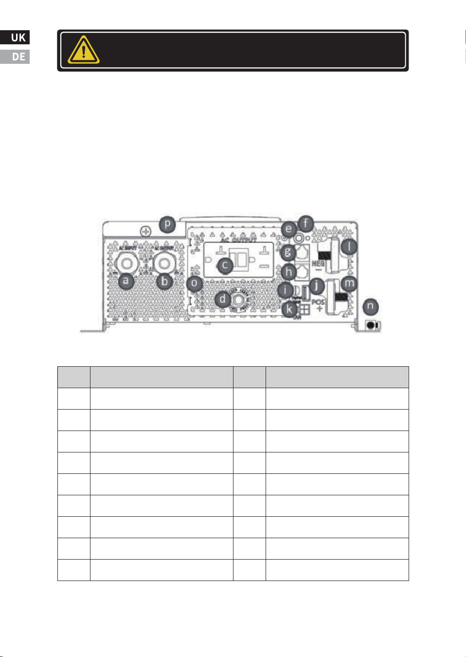
Main Unit Front
CAUTION
���V GFCI SERIES
Item
a
b
c
d
e
f
g
h
i
Description
AC input Hardwire Cable strain Relief
AC Output Hardwire Cable strain Relief
AC Output Socket
AC Output socket Ciruit Breaker
Power button
Power Indicator
Remote Port
Battery Temperature Sensor Port
lgnition Start Port
Description
Program Port
CAN BUS Port
DC Negative Stud
DC Positive Stud
Chassic Groud Connector
AC Output Wiring Compartment
Ac Input & Output Wiring Compartment
Fans and fan guards
Item
j
k
l
m
n
o
p
q
-�-
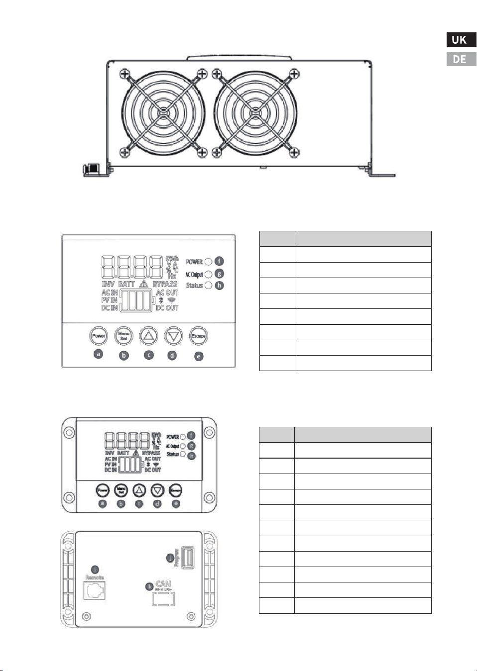
Main Unit Rear
Multi-Function Display
Remote Control Display Panel(Optional)
Item
a
b
c
d
e
f
g
h
Description
Power button
Menu button
Up button
Down button
Escape button
Power indicator
AC output indicator
Status indicator
Item
a
b
c
d
e
f
g
h
I
J
K
Description
Power button
Menu button
Up button
Down button
Escape button
Power indicator
AC output indicator
Status indicator
Remote Panel Socket
Program Port
CAN-BUS port
Fans and fan guards
-�-
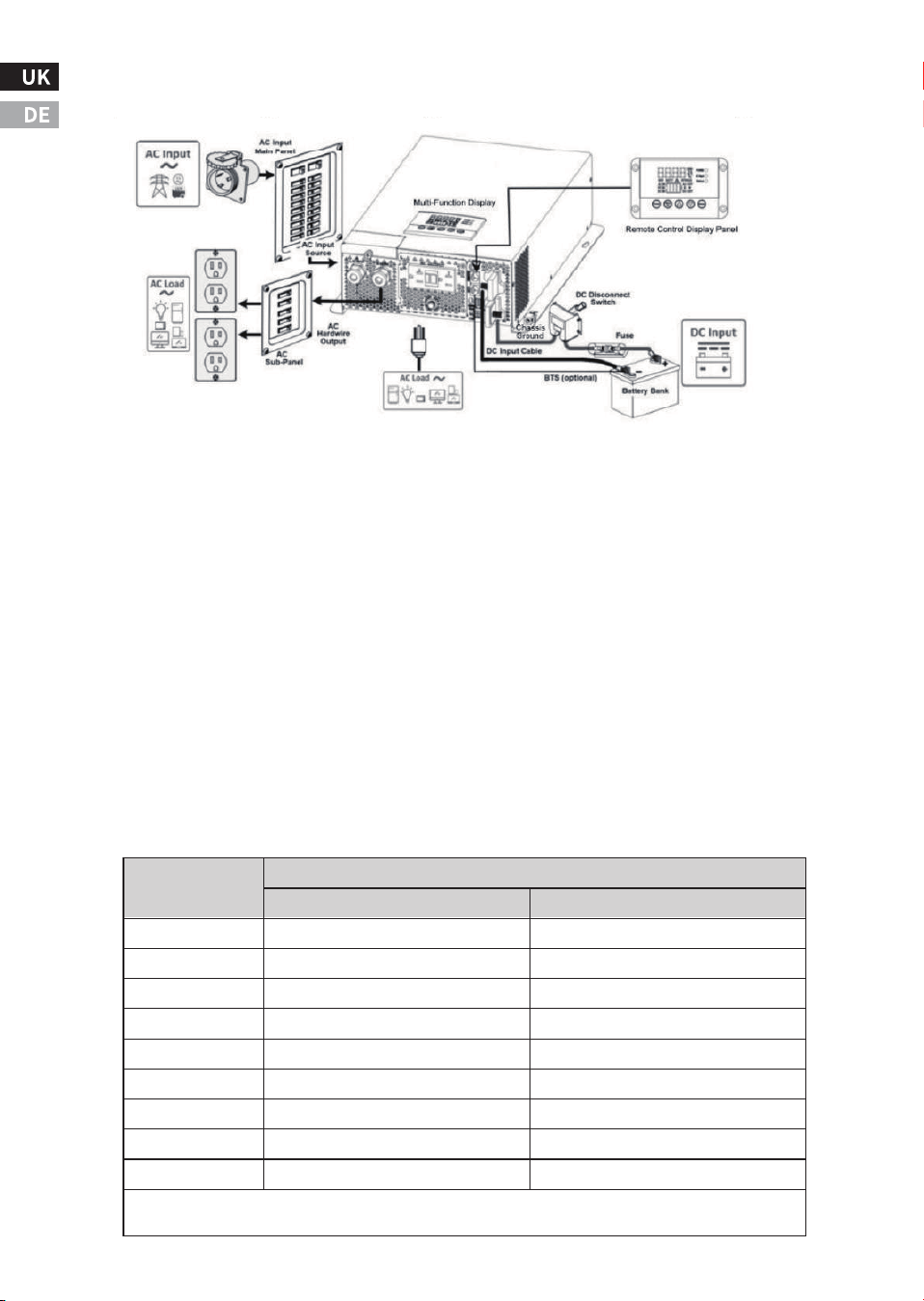
Typical Wiring Block Diagram of Inverter-Charger
● Battery Bank
* The converter/inverter is intended to recharge batteries. The battery
that is connected to this product is only suitable if it complies with the
given battery standard for that battery type, and is provided with a
battery management system that will monitor and control the electri-
cal and thermal health of the battery during charging. When installing
this converter/inverter, the battery is to be verified as in compliance
with the applicable battery standard.
* The use of deep cycle or lithium ion battery is highly recommended
for power inverter application.
* For battery size, you need to identify how much and for how long
the inverter has to provide AC power to the loads (based on Amps x
hour energy consumption). It is recommended to purchase as much
battery capacity as possible.
��W
���W
���W
���W
����W
����W
����W
����W
����W
AC Load
��V/���AH
�� hrs.
��.� hrs.
� hrs.
� hrs.
�� mins
�� mins
�� mins
N.R.
N.R.
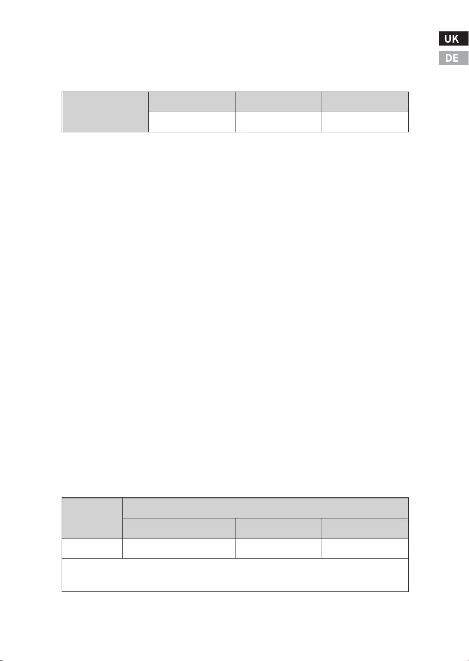
Estimated run time on ��V Battery bank on ��V Input Models
N.R.- Not Recommended. Based on more than �C discharged on battery capacity.
Estimated run times are for reference use only. Actual run times may vary on battery type used.
��V/���AH
�� hrs.
�� hrs.
�� hrs.
� hrs.
� hrs.
� hrs.
�� mins
�� mins
�� mins
● DC Fuse or Circuit Breaker
* DC-rated fuse or DC-rated circuit breaker connected along the DC
positive line is required.
* Based on the size of the Battery Bank, determine the overall short
circuit current rating of the battery bank from the battery manufac-
turer. The fuse or circuit breaker has to be able to withstand the short
circuit current that can be supplied by the battery bank.
* For battery banks with total capacity under ���Ah, the most afford-
able ANL fuse type can be used. Otherwise please use Class-T type.
● DC Disconnect Switch
* A DC Disconnect Switch connected along the DC positive line is
recommended. The rating of the switch is with the same or higher
rating of the selected fuse or circuit breaker. Use ignition protected
switches when required by local codes.
* This switch is used to disconnect the positive of the battery bank to
the unit's positive terminal during maintenance/repair service, when
not in use, or when troubleshooting. It could also be an A/B/A+B/OFF
type switch to select either one of the two or both(paralleling) battery
banks (if available).
● DC Input Cable
* All DC Input Wires should be insulated multi-strand low resistance
wires.
* The DC wires must be copper and with minimum ���℃ rating.
-�-
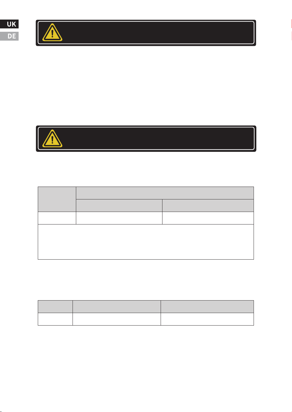
The typically recommended wire length is limited to � feet or less for each of the positive and
the negative. For longer wires, a proportionally thicker gauge is required to compensate for
additional voltage drop.
Fuse/Circuit
Breaker Rating
��V ����W System ��V ����W System ��V ����W System
��� Adc ��� Adc ��� Adc
Model
��V ����W
series
≤ � feet (Recommended) ≤ �.� feet
Thinnest DC Input Wires Gauge Used
< �� feet
���mm�AWG #�/� ���mm� ��� kcmil (MCM) ���mm� ��� kcmil (MCM)
● AC Input Source
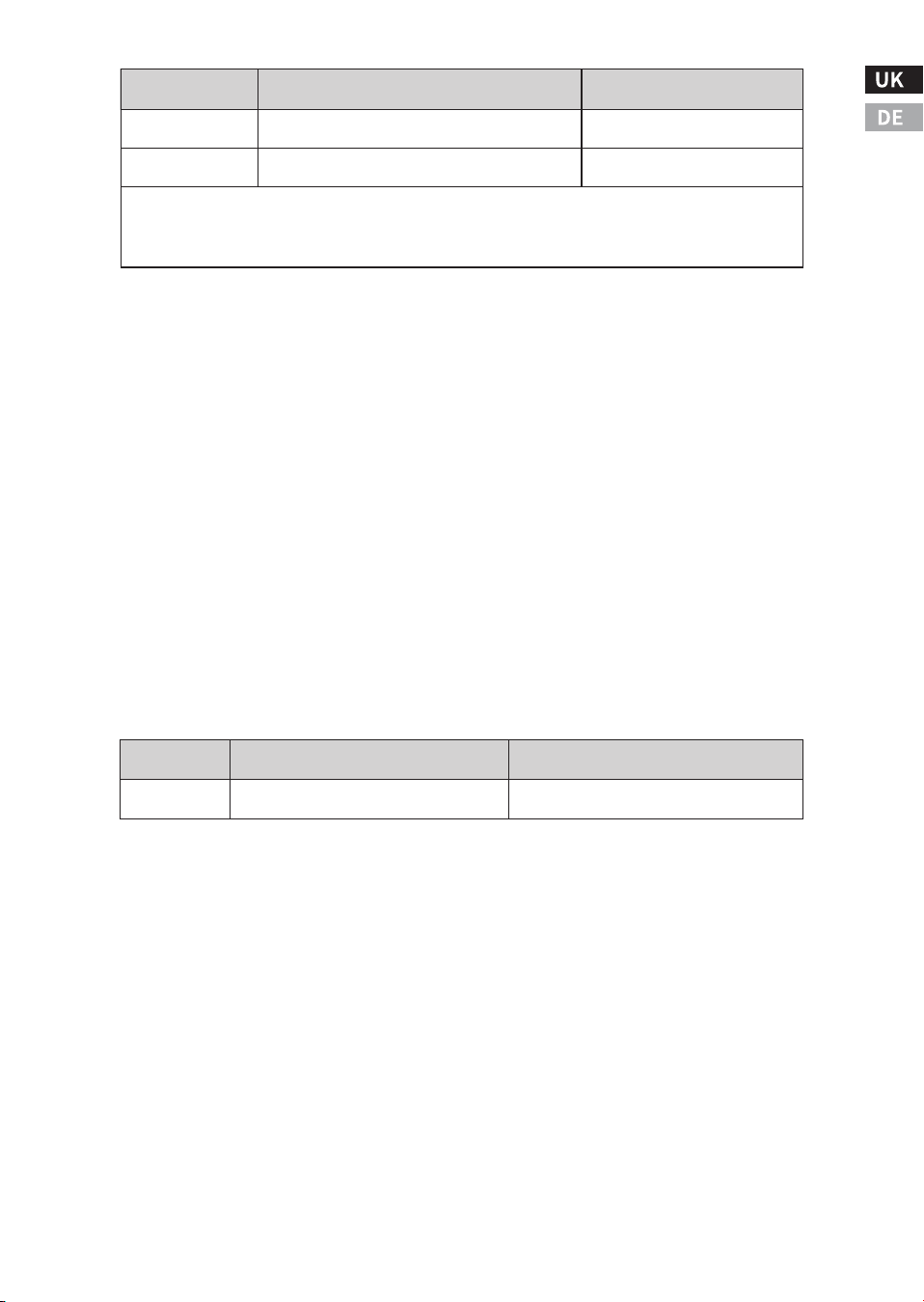
An AC source is usually qrid power or an AC Generator. The acceptable
AC Input voltagerange and frequency are as shown:
An automatic or manual AC source selector switch can be used to
switch between the multiple sources of shore power to the unit.
Usually, the AC Main Panel includes a main circuit breaker that serves
as over-current protection and as a disconnect for the AC shore power
supply line. Additional AC circuit breakers serve individual circuits
and one of the AC circuit breakers will serve the unit. During By-Pass
mode, the AC Input source will serve the AC Output Load and also the
AC Input current for the charger when it is used to charge the battery.
These guidelines assume you are using the DC supplied cable and
fuse sizes recommended in this manual. The use of a thinner gauge in
the DC wires may cause the inverter to trigger the under-voltage shut
down under heavy load conditions. It may also melt the wire insula-
tion and catch fire, resulting in death or serious injury. The choice of
the wire gauge should also match or exceed the ampacity rating of
the DC fuse and holder being used.
● Chassis Ground
The unit chassis has to be grounded properly before use. Never oper-
ate the unit without proper grounding. Failure to do so will result in
death or serious injury.
-��-
DANGER!
CAUTION
- These guidelines assume you are using the DC supplied cable and fuse sizes recommended in
this manual. lf you are using different sizes, refer to the applicable installation code for the
DC grounding detail.
- In marine applications, the main AC-DC ground bonding may require galvanic isolators to
manual avoid galvanic corrosion.Check your local electrical codes (i.e. NEC UL, ABYC...).
Model
��V ����W
series
Recreation Vehicle Marine
Thinnest Wire Gauge Used
Acceptable Ac Input Voltage Range
Model
Acceptable AC Input Frequency Range
��-��� VAC
���VAC series
��-��� Hz
��mm²/AWG # � AWG# �/�
The unit is designed to accept non-Sine wave AC Input Source
supplied by a generator.
● AC Hardwire Output
An AC Sub-Panel is recommended to incorporate an AC output circuit
breaker and breakers for individual load circuits. Use the same wire
size as the one used for the AC input wire.
● AC Output Socket and
● AC Output Thermal Breaker
A single AC Output socket is provided for direct AC output from the
unit. An over-current protective device (thermal breaker) is connect-
ed in series with the AC Output Socket to avoid excessive current
being drawn from it.
● Multi-Function Display
The display is used to provide unit information and for unit setting.
● Remote Control Port
The port is used to connect to the Remote Control Display. And it is
used to provide unit information and for unit setting.
-��-
Model
���VAC series
���VAC series
AC Input Circuit Breaker to serve the unit
��A(maximum)
��A(maximum)
AC Input Wire
�mm�/#�� AWG(minimum)
�mm�/#�� AWG(minimum)
- Follow the electrical and/or building code when you choose AC Branch Breaker and AC Input
wire Size. Connect the unit to any AC Input Source.
- Smaller size AC input wire can be used when a lower amperage rated AC input Circuit Breaker
is used from upstream to feed the unit.
AC Output Socket Type
Model
AC Output Thermal Breaker
NEMA �-�� GFCI
���VAC series
��A
● BTS Port
The port is used for connecting to the optional Battery Temperature
Sensor. The thermistor installed inside the ring terminal is used to
measure the battery terminal temperature and the unit will make
compensation on battery charging voltage for battery charging.
● Ignition Start Port, Program Port, CAN-BUS Port
The Ignition Start Port is used for connecting to the ignition start
signal from vehicles to control the operation of the inverter.
Program Port
This USB port is for system firmware upgrade use only. This CANNOT
be used for charging Smart phones or USB powered devices. Misuse
of this port can potentially damage the unit and is not covered by the
warranty. The USB port is located on the Inverter-Charger and an
extra port that shares the same function is also located on the back of
Remote Control Display.
CAN-BUS Port
This is for unit communication through the CAN interface. Misuse on
this port can potentially damage the unit and is not covered by the
warranty. This port is located on the Inverter-Charger and an extra
port that shares the same function is also located on the back of
Remote Control Display.
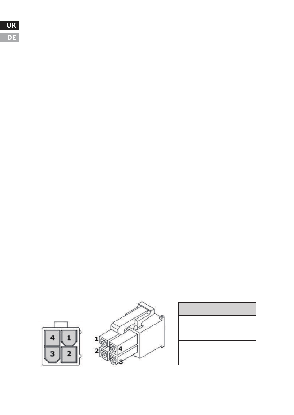
Information on the CAN-BUS plug/connector:
* Input voltage: � VDC - �� VDC
* Input amperage: �mA typical, ��mA Max @��V
-��-
CAN-BUS
Connector(on inverter)
Pin
�
�
�
�
Designation
PS-
CANH-H
CAN-L
PS+
CAN-BUS PIug
(cable end)
* DO NOT install the unit near flammable fumes or gases (such as
propane tanks or large engines).
* AVOID covering the ventilation openings. Always operate unit in an
open area.
Choosing the location:
* The unit should only be installed in locations that meet the follow-
ing requirements. Do not allow water or other fluids to drip or splash
on the unit.
* Environment temperature should be between -� °F and ��� °F (-��
°C and �� °C).
* Allow at least three inches of clearance around the unit. The more
clearance for ventilation around the unit, the better the performance
is.
Mounting the Unit:
* Choose an appropriate mounting location.
* The unit can be mounted in any direction.
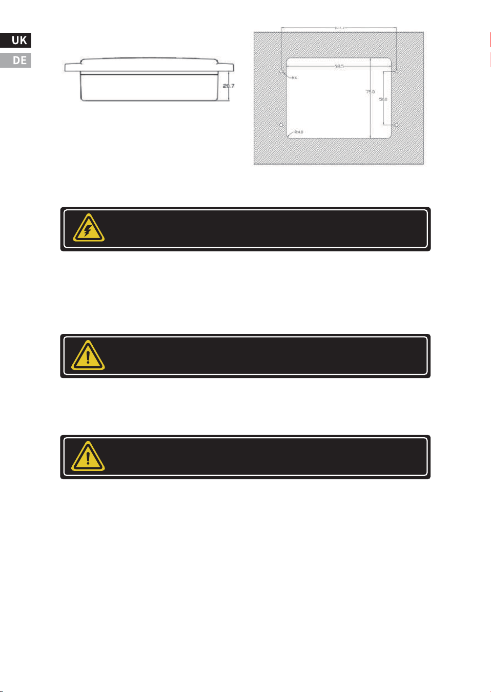
* Use the mounting template below to mark the positions of the
mounting screws.
* Drill the � mounting holes,place the unit in position and fasten the
unit to the mounting surface.
V. Installing The Unit
-��-
WARNING:
Explosion hazard!
12V / 3000W / 100A
INVERTER CHARGER
PURE SINE WAVE
OUTPUT
-��-
DC Input Connection:
The unit “On/Off ” switch does not disconnect the DC power from the
battery. Use the DC Disconnect Switch or disconnect the DC input
cables to disconnect the DC power from the battery before working
on any circuits connected to the unit. Failure to follow these instruc-
tions can result in death or serious injury.
Reversing the DC Input terminals will damage the unit and it cannot
be repaired. Damage caused by reverse polarity connection is not
covered by the warranty.
Field wiring Dc terminals tightening torque �� - �� Nm
* Connect a negative DC Input cable between the unit DC negative
terminal and battery negative terminal.
* Make sure the Disconnect Switch is in the OFF position. Connect a
positive DC Input cable between the unit DC positive terminal and
one terminal of the Disconnect Switch.
* Connect another DC Input cable between the other terminals of the
Disconnect Switch to one side of the terminal of the fuse holder or DC
rated circuit breaker(OFF position).
WARNING!
Electrical Shock Hazard!
CAUTION
IMPORTANT
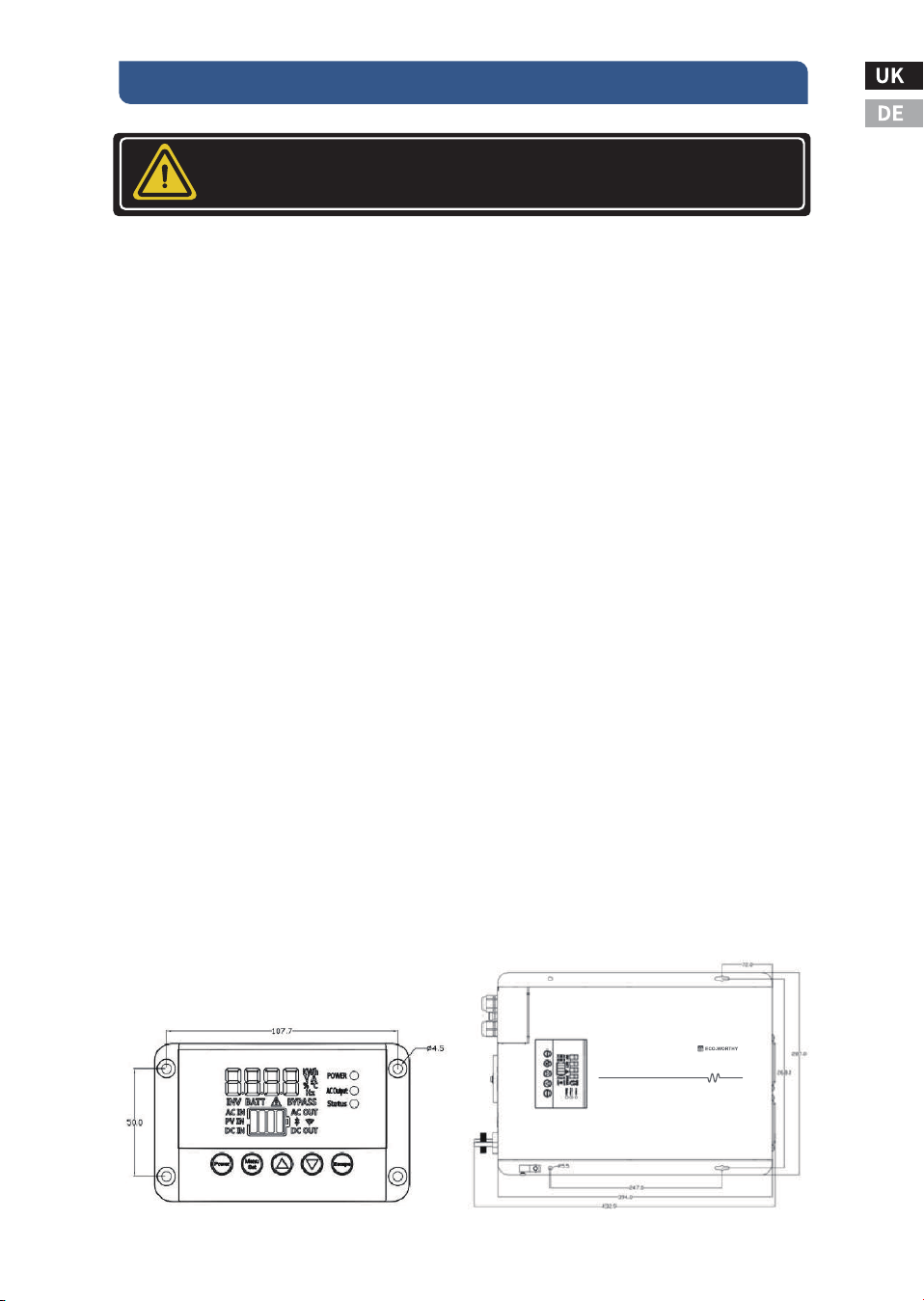
Remote control display panel
(All dimensions in mm)
* Connect another Dc input cable between the other terminal of the
fuse holder or DC rated circuit breaker to the battery positive termi-
nal.
Note: For Marine application, either the DC fuse or DC rated circuit
breaker needs to be installed within � inches (�� cm) from the battery
positive terminals.
* Install the selected fuse to the fuse holder.
Chassis DC Ground connection:
* Connect the grounding wire to the unit’s Chassis DC Ground Lug
located near the DC Input terminal and the other side of the cable to
the common grounding point.
* For a Recreation Vehicle, the common ground point is usually the
vehicle chassis or a dedicated DC ground bus.
* For Marine, the common ground point is usually the DC ground bus
or engine negative bus.
Note: Do not use the Chassis DC Ground Lug for your AC Grounding.
For AC Grounding, see AC Wiring instructions for more details.
AC Input and AC Output Hardwire Connections:
Before making any AC Input and AC Output Hardwire connection,
please be sure the AC Input Source is not energized and the DC
disconnect switch is switched OFF. Please double check the location
of the AC input connector located inside the wiring compartment.
Misconnecting to the AC output connector inside the same compart-
ment will damage the unit and may cause fire.
-��-
WARNING!
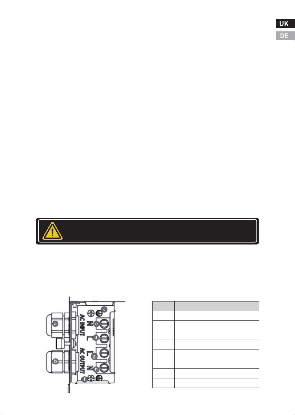
Item
a
b
c
d
e
f
g
h
Description
AC INPUT STRAIN RELIEF
AC OUTPUT STRAIN RELIEF
AC INPUT GROUND
AC INPUT LIVE
AC INPUT NEUTRAL
AC OUTPUT GROUND
AC OUTPUT LIVE
AC OUTPUT NEUTRAL

Remove the AC wiring compartment cover by unscrewing the one
screw located at the front of the AC wiring compartment cover.
For AC Input connections:
* Insert the AC Input cable through the AC input Strain relief on the
unit.
* Connect the AC Main Panel AC Ground wire to the AC Input Ground
terminal on the unit.
If a solid ground wire is used, the wire can be connected directly
under the screw head. If a stranded ground wire is used, ring termi-
nals must be used.
* Connect the AC Main Panel AC Live to unit's AC Input 'L' Live termi-
nal.
* Connect the AC Main Panel AC Neutral wire to unit's AC Input Neutral
'N' terminal.
* Tighten the strain relief to secure the AC Input wire.
For AC Output Hardwire connections:
* Insert the AC Output cable through the AC Output Strain relief on the
unit.
* Connect the AC Sub-Panel AC Ground wire to the AC Output Ground
terminal on the unit. If a solid ground wire is used, the wire can be
connected directly under the screw head. If a stranded ground wire is
used, ring terminals must be used.
* Connect the AC Sub-Panel AC Live to unit's AC Output 'L' Live termi-
nal.
* Connect the AC Sub-Panel AC Neutral wire to unit's AC Output
Neutral 'N' terminal.
* Tighten the strain relief to secure the AC output wire.
Remote Display Connection:
Route the Rj�� cable from the unit to your desired location for the
Remote Control Display and connect one end of the cable to the main
unit Remote Port and the other end of the cable to the Display Panel
socket located at the rear panel of the Remote Control Display.
-��-

BTS(Battery Temperature Sensor) Connection (optional):
To provide more accuracy and precision on battery voltage charging
against battery temperature, a BTS (sold separately) can be used. The
BTS can also be used to terminate the charging cycle when it senses
the temperature of the battery rise to above �� °C or fall below � °C.
See "Understanding the Error Code ” E�� -E�� for more details. Use
the following procedures to install the BTS.
* Connect the Rj�� end of the BTS cable to the BTS Port on the main
unit.
* Install the ring terminal end of the BTS cable to the negative termi-
nal of the battery bank.
Ignition Start Port Connection (optional):
The ignition start connection provides an inverter ON/OFF function
through the Ignition Start Port. See more details on Understanding of
Ignition Start On/Off function.
Quick Test on Unit after Installation:
* Connect a small Ac load like a ��W light bulb to the AC Output of the
unit.
* Switch DC disconnect switch to ON to provide battery power to the
unit, then press and hold On/Off button on Main unit or 'Power'
button on Display panel for � second to turn unit or inverter ON.
* The 'Status' LED on display will turn Amber indicating inverter is ON.
AC Output LED turns green indicating the AC is available.
* Verify the ��W light bulb is ON.
* Switch ON the Main Circuit Breaker on the AC Input Panel.
* Switch ON the Ac Input Circuit Breaker that provides AC input power
to the unit.
* If AC input source is available, the 'Status' LED amber will flash for
about �� seconds indicating the AC input source is available. It will
then turn to solid green or flashing green indicating the unit is
running from the Ac input source.
* Verify the ��W light bulb remains ON.
* The unit is successfully installed and functioning properly.
-��-

Ground Fault Circuit Interrupters (GFCIs)and Monthly Testing
(���VAC ����W/ ����W/����W model)
A GFCl is a device that de-energizes a circuit when a current to ground
exceeds a specified value that is less than that required to blow the
circuit breaker. GFCls are intended to protect people from electric
shocks and are usually required in wet or damp locations.
Installations in marine and recreation vehicles require GFCl protec-
tion of branch circuits connected to the AC output of the unit.
For units equipped with GFCl, the GfCl function is required to be
tested monthly
* To test the GFCl, turn unit ON either in By-Pass mode or battery
power mode. Plug a small AC load (e.g. ��W light bulb) to the AC
Output GFCl Socket.
* Check that the AC load is ON.
* Press the 'TEST' button to trip the GFCl protection. A clicking sound
should be observed. Check that the AC load is turned off.
* Press the 'RESET' button until hearing a click to reset the GFCl
outlet.
* Check that the AC load is back ON again.
Note: Be aware that a tripped GFCl outlet cannot be reset with the
unit operating in Battery Power Mode and with the Load Sense
setting activated. Turn load Sense feature Off before resetting the
tripped GFCl.
How to Reset the GFCl outlet when tripped (���V AC
����W/����W /����W model if available):
When Utility AC input Source is available:
* Unplug all the AC loads from the unit's GFCl outlet.
* Press the 'RESET’ button until hearing a click to reset the GFCl
socket.
* Plug in the AC Loads and verify the AC Load is ON.
When Utility AC Input Source is not available:
* Unplug all the Ac loads from the unit's GFCl outlet.
* Turns unit On and be sure the unit is running in Battery Power Mode.
* Check/Set the Load Sense 'F��’ setting to off.
* Press the 'RESET’ button until hearing a click to reset the GFCl
socket
* Press the 'RESET’ button until hearing a click to reset the GFCl
socket
-��-
* Plug in the AC Loads and verify the Ac Load is ON.
Note: Be aware that a tripped GFCl outlet can only be Reset when
there is a continuous AC input supplying to the GFCl Socket.
The unit is preset with factory default settings and will fulfill the basic
needs for inverter-charger operation. The display is used to provide
information about the unit status and the unit function can be
customized through the Display.
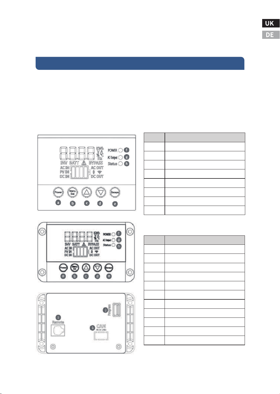
Understanding the Indicator/Push Button/Unit Functions
-��-
V. UNIT OPERATION
Item
a
b
c
d
e
f
g
h
Description
Power button
Menu button
Up button
Down button
Escape button
Power indicator
AC output indicator
Status indicator
Item
a
b
c
d
e
f
g
h
I
J
K
Description
Power button
Menu button
Up button
Down button
Escape button
Power indicator
AC output indicator
Status indicator
Remote Panel Socket
Program Port
CAN-BUS port
Normal Operation
When unit is On, the Multi-Function display shows Battery Voltage "V'.
Pressing any button will illuminate the backlighting of the display for
about �� seconds.
'Power’ button (Same function as the green 'On/Off' push button on
the main unit):
- To turn the inverter ON: press and hold until hearing the beep (in
about � sec.). All icons in the display turn ON, followed by the Display
revision levels 'Dx.x' and then the Display revision levels 'rx.x' (where
x= any number).
- To turn the inverter OFF: press and hold until hearing the beep (in
about � sec.). Display turns off and the unit cannot be turned on again
but after about � sec (when hearing the deactivation of the internal
relays).
Note: When AC input is available, this 'Power' button cannot be used
to turn OFF the unit.
Menu/Set button:
- Press once to view unit setting on display. See more details on View-
ing and Change Unit Setting section.
▼and ▲ button:
- The ▲ or ▼ V can be used to scroll through DC Current 'A’ , AC
Output Power 'KW' and Battery Voltage 'V'.
- Press and hold ▲ and ▼ buttons together for � seconds to show
firmware revision numbers.
-��-
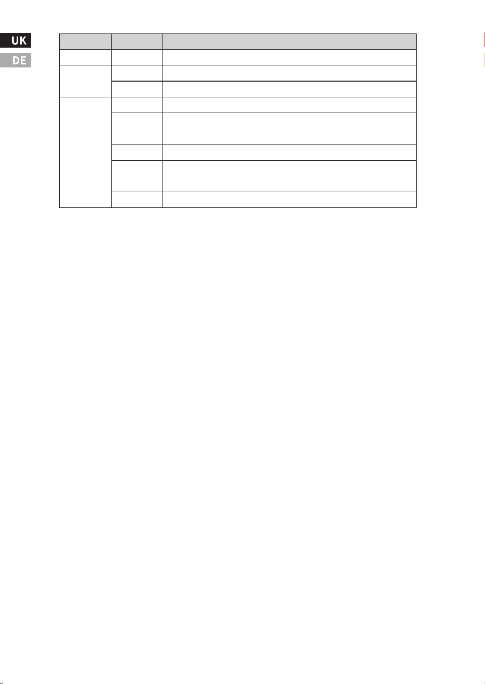
Indicator
Power
AC
Output
Status
Status
ON
ON
OFF
Green
Green
(Flash)
Amber
Amber
(Flash)
Red
Unit is power ON.
AC output is available.
AC output is not available.
AC Output is running from Utility.
AC Output is running from utility and battery charger is charging
the battery.
AC Output is running from Inverter.
Utility is detected and is under verification. AC Output is still running
from inverter and will switch to Utility in about �� seconds.
Error/Warning occurs. Display will show Error or Warning code.
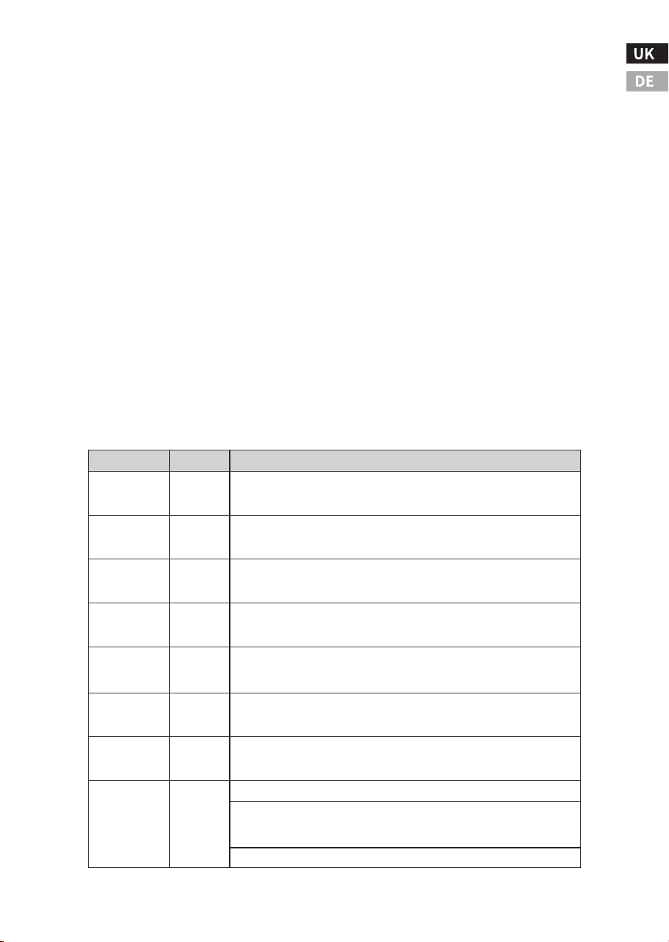
Function
Unit Setting
Display
F��
��.�*
F��
��.�*
Battery Low
Disconnect
Battery Low
Warning
Description and Available Setting
- 'Escape' button: Press once to return back to Normal Operation.
- Press and hold for � seconds to turn OFF or ON the AC Output Switch
(Optional)
(Use this button as an AC Output ON/OFF function for the Output)
Viewing and Change Unit Setting
- When unit is in normal operation mode, Press "Menu/Set' button
once to view unit setting as listed on the Unit Setting Function Chart.
- The ▲ or ▼ button can be used to scroll through each unit setting. If
a particular setting needs to be modified, press and hold the
'Menu/Set' button for � seconds and the set parameter will flash on
the display. Use the ▲ or ▼ button to scroll through the available
settings. Once the desired setting is chosen, press and hold the
'Menu/Set’ button until a beeping sound occur and the new setting is
saved.
- Press 'Escape' button once to return back to Normal Operation. (If
none of the button is triggered for about � seconds, display will also
return back to Normal Operation.)
Unit Setting Function Chart
-��-
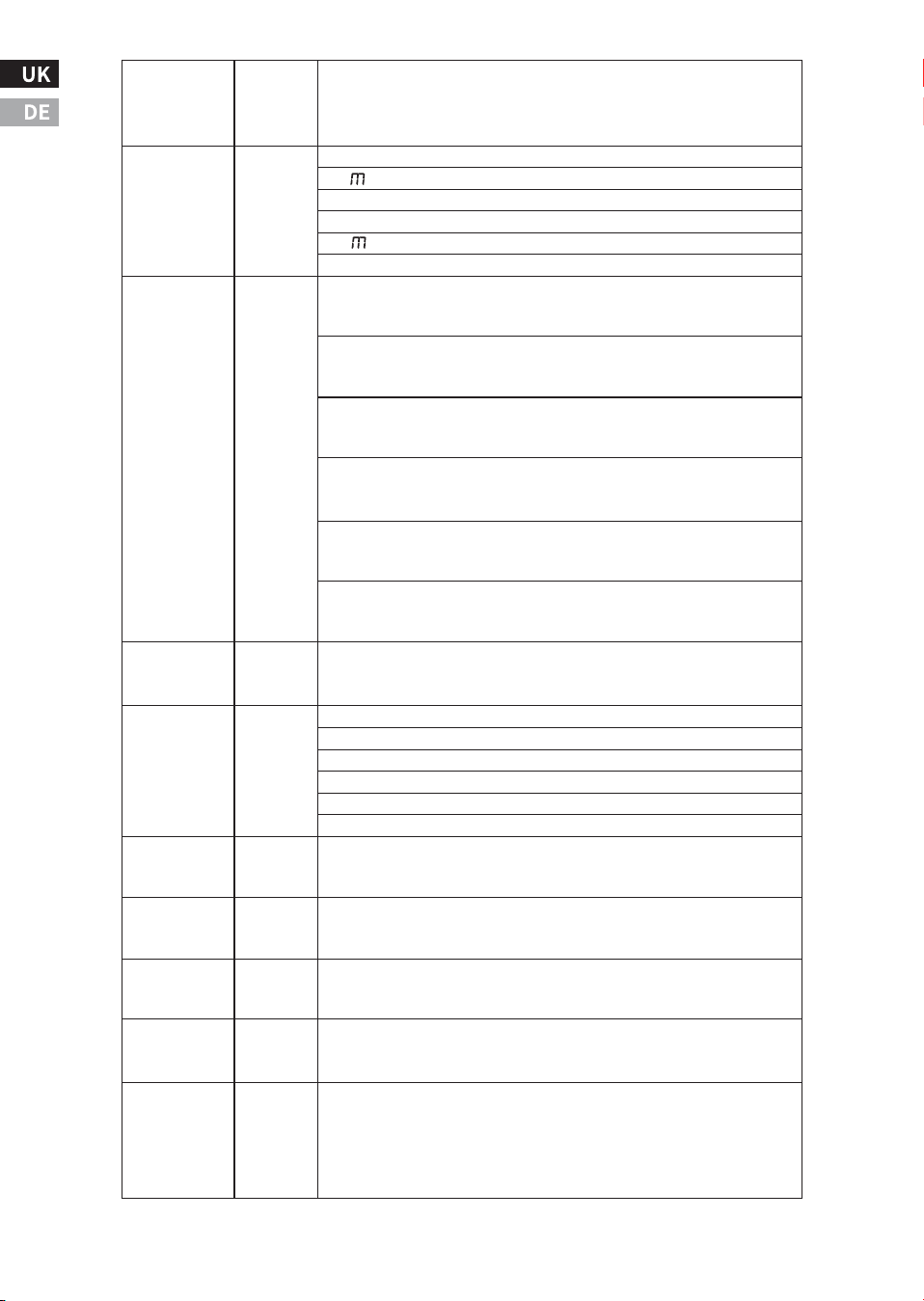
Battery Low Disconnect Voltage selectable ranges is ��.� -��.�V
(�.�Vsteps)* (Default voltage is set to ��.�V*)
Battery Low Warning Voltage selectable ranges is ��.� - ��.�V (�.�V
step)*(Default voltage is set to ��.�V*)
F��
��.�*
Battery Low
Recovery
Battery Low Recovery Voltage selectable ranges is ��.� - ��.�V (�.�V
step)(Default voltage is set to ��.�V*)
F��
OFF
Power Save
Time
The range is from � to ��, adjusted by �-h increments. The next
Setting after �� is OFF. When total load is less than ��W.
F��
OFF
Load
Sense
OFF (Default): Continuous AC Output when inverter is ON
�� : Continuous AC Output when inverter is ON and Ac load is > ��W
�� : Continuous AC Output when inverter is ON and Ac load is > ��W
F��
��.�*
Audible
Buzzer
Battery Low Warning Voltage selectable ranges is ��.� - ��.�V (�.�V
step)*(Default voltage is set to ��.�V*)
ATO(Default): Auto Backup. Inverter automatically turns ON when
ACBlackout.
F��
ON
Battery Low
Warning
ON (Default): Buzzer is enabled. Unit buzzes when Warning or Error
occurs OFF: Buzzer is disabled. Unit does not buzz when Warning
and Error occur.
INV :Use as Inverter only. No By-Pass functions
OFF: Inverter function is disabled. No AC backup when AC Blackout.
F��
ATO
Inverter
-��-
F���
���*
F��
ON
F��
GEL
F��
��.�*
AC Charger
Battery
Type
Bulk/Absorpt-
ion Voltage
6EL
A6
d
li
p6
p5y
Bulk
Current
��V/����WModels:
Selectable Ranges ���A,��A,��A,��A,��A(Default ���A).
(Default): GEL Battery, default Bulk Charge/Float Voltage is��.�V/��.�V*
: AGM Battery, default Bulk Charge/Float Voltage is ��.�V/��.�V*
: Flooded Battery, default Bulk Charge/Float Voltage is ��.�V/��.�V*
: Lithium Battery, default Bulk Charge/Float Voltage is ��.�V/��.�V*
: Program, default Bulk Charge/Float Voltage is ��.�V/��.�V*
: Power Supply Mode, Default Power Supply Voltage is ��.�V
F��
��A
Absorption to
Float Current
F��
��.�*
Float
Voltage
F��
��.�*
Recharge
Voltage
F��
Nor
Battery
Temperature
F��
��A
AC Input
Source Circuit
Breaker
F��
OFF
Equalize
Charging for
Flooded
Battery
��V/����W Models: Selectable Range: ��A,��A, ��A, �A,�A (Default ��A)
��V/����W Models: Selectable Range: ��A,��A, ��A, �A, �A (Default ��A)
��V/����W Models: Selectable Range: ��A, ��A, �A, �A, �A (Default �A)
��V/����W Models: Selectable Range: �A, �A, �A, �A, �A (Default �A)
��V/����W Models: Selectable Range: �A, �A, �A, �A, �A (Default �A)
��V/����W Models: Selectable Range: �A, �A, �A, �A, �A (Default �A)
��V/����W Models:
Selectable Ranges ���A,��A,��A,��A,��A(Default���A).
��V/����W Models:
Selectable Ranges ��A,��A,��A,��A,��A(Default ��A).
��V/����W Models:
Selectable Ranges ��A,��A,��A,��A,��A(Default ��A).
��V/����WModels:
Selectable Ranges ��A,��A,��A,��A,��A(Default ��A)
��V/����W Models:
Selectable Ranges ��A,��A,��A,��A,�A(Default ��A).
Float voltage is based on the battery type chosen. All battery types
have selectable ranges of��.�-��.�V. (Default on GEL Battery is
��.�V*)
Battery Recharge Voltage Selectable Range: ��.� to ��.�V (�.�V
step)*(Default on GEL, AGM, Flooded, PGM battery setting is ��.�V*
and Libattery setting is ��.�V)
Hi: High > �� °C
Nor (Default): Normal �� -��°C
Low : Low < ��°C
��� Vac Models: Range: ��A,��A,��A (Default ��A).��� Vac Models:
Range:��A,��A,��A(Default ��A on EU, ��A on UK and AU).
OFF(Default):CHG EQU is disabled.
�H : only one hour of equalize charging once.
This setting is only available when Flooded battery type is selected.
lt allows only one hour to equalize charging once.
Bulk/Absorption voltage is based on the battery type chosen. All
battery types have selectable ranges of ��.�-��.�V*.(Default on GEL
Batteryis��.�V*)
ON (Default): AC Charger is enabled. Charge battery when AC input
is available.
OFF:AC Charger is disabled. No battery charging when Ac Input is
available.
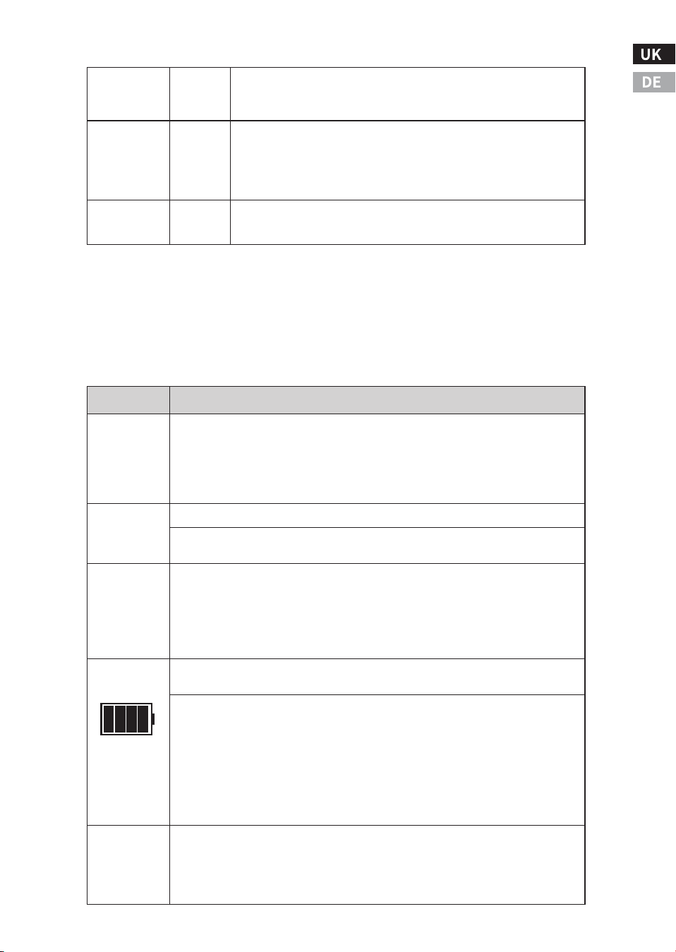
*For ��V Models (LF-BIC��������, LF-BIC��������, LF-BIC��������,
LF-BIC��������, LFB�C��������, LF-BIC��������), all voltage
values are doubled.
Understanding the Display Icons during Unit Operation
-��-
Icons
Meaning
BYPASS
AC IN
AC OUT
Solid: Unit is running in ByPass mode. (The transfer switch is switched to AC
Input Source).
- AC Output power is running from AC Input Source.
- AC Output is available at both the AC Output socket and the AC Output
Hardwireterminal (indicated by AC Output indicator located on the right side
of the Display)
Solid: Unit is running in Battery Mode (The transfer switch is switched to
inverter)
- AC Output power is running from the inverter
- AC Output is available to both the AC Output socket and the AC Output
Hardwire terminal (indicated by AC Output indicator located on the right side
of the Display)
Battery
Inverter
Mode
Battery bar(s) in solid indicates the unit is in Battery Mode. The bars show
estimated remaining battery power.
� solid bars: Battery is Full
� solid bars: Battery capacity with ��% remaining
� solid bars: Battery capacity with ��% remaining
� solid bar: Battery capacity with ��% remaining
No bar: Battery is empty. Inverter will shut down when it reaches under-volt-
age shutdown point.
Note: This indicator is for reference use only. lt varies depending on battery
health or type used.
Battery bar(s) with the last bar flashing indicates the unit is running in Bypass
mode andthe battery charging process is in progress. The charging stages are
indicated by and the number of bars.
Solid: AC Input is available and is in the operating range
Flashing: AC Input is detected and is under verification before switching to
Bypass mode. This normally takes about �� seconds.
F��
��HZ
F��
���V
Output
Frequency
Output
Voltage
��HZ or ��HZ
After changing the output frequency setting, turn the unit off and
then on again, in order for the change to take effect.
���V Series Output Voltage Range: ���V, ���V, ���V; (Default
���V���V Series Output Voltage Range: ���V, ���V, ���V; (Default
���V)After changing the output Voltage setting, turn the unit off
and then on again, in order for the change to take effect.
F��
no
Factory
Default
Select to reset all settings to default.
YES
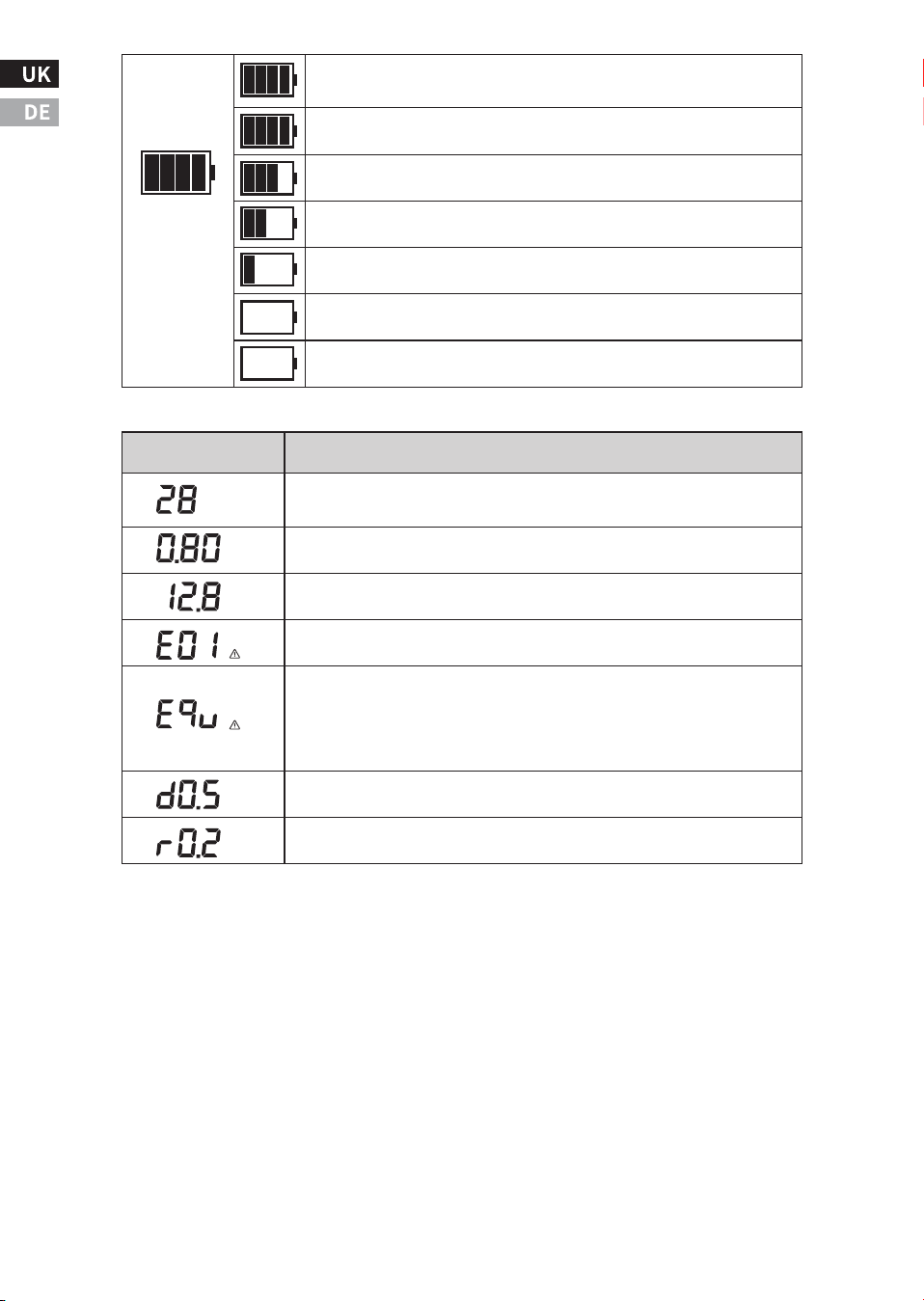
-��-
Display Character
Meaning
� bars in solid: indicates the battery is fully charged and it is in Float
stage.
The last bar flashing: indicates the battery is in Absorption charging
stage.
The third bar flashing: indicates the battery is in Bulk charging stage
and the battery is >��.�V.
The second bar flashing: indicates the battery is in Bulk charging
stage and the battery is >��.�V.
The first bar flashing: indicates the battery is in Bulk charging stage
and tthe battery is > ��.�V.
'A' icon on indicates the display shows battery discharge current (��A
as shown)
"KW' icon on, it indicates the display shows AC Output power in
KW(�.�� KW = ���Was shown)
'V' icon on, it indicates the display shows battery voltage in V (��.�V
as shown)
Warning icon on, it indicates the display shows Error/Warning Code
(E�� as shownBattery Low Disconnected error)
Indicating the Display Panel firmware revision
Indicating the Main Unit firmware revision
Equalization on Flooded battery is in process. This function is
available for use with Flooded battery type only. The display will also
show the equalization voltage during theprocess. Follow the
instruction provided by the battery manufacturer when performing
the equalization process.
No bar: indicates the battery is in Bulk charging stage and the battery
is >��.�V.
Battery icon flashing: indicates the battery is in Bulk charging stage
and the battery is below ��.�V.
Charger
Mode
A
KW
V
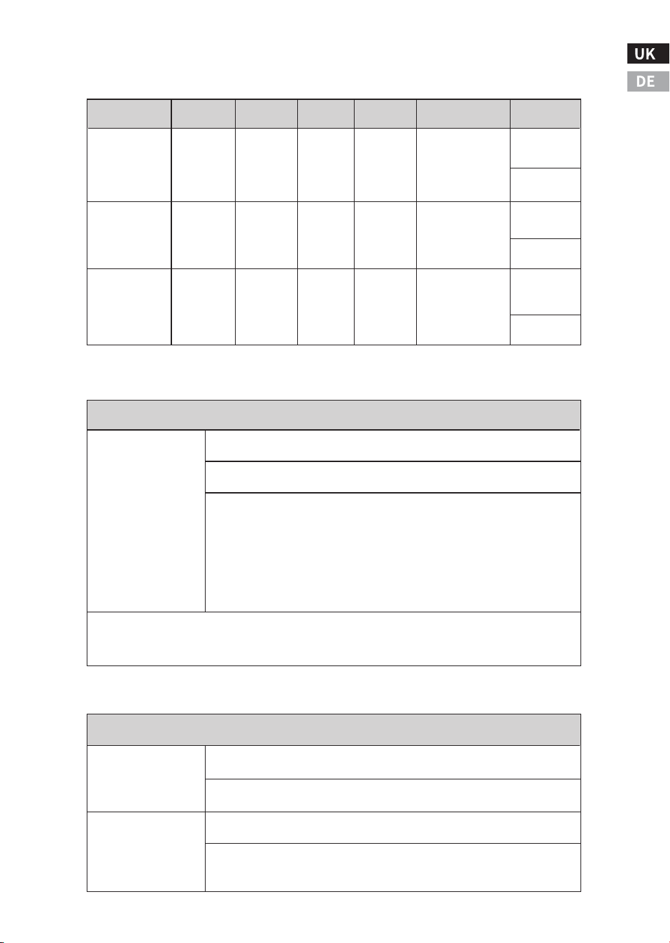
Exploring the Unit Settings
a) Inverter and Charger Functions
b) Load Sense Function
c) Battery Disconnect Function
-��-
This Load Sense function is only effective when the unit is running as
inverter(Battery power) mode.
'Off' : Unit provides continuous AC Output power all the time.
��: Load Sense power setting is set to ��W. Unit will provide continu-
ous AC Output only when the AC load connected to the AC Output is
>��W. AC Output will switch back to pulsing AC Output every few
seconds when the AC Load connected is approximately ��W or less.
��: Load Sense power setting is set to ��W. Unit will provide continu-
ous AC Output only when the AC load connected to the AC Output is
>��W. AC Output will switch back to pulsing AC Output every few
seconds when the AC Load connected is approximately ��W or less.
* The Load Sense Power rating is available at power levels of ��W and ��W.
* This setting is designed to reduce battery power when the unit is running as invertei and the
AC Load demand is small.
Load Sense Mode
F��
F��
��.�
F��
��.�
Battery Low Disconnect Voltage selectable range: ��.� - ��.�V (�.�V
step)(Default ��.�V)
The Battery Low Disconnect Voltage has to be with a minimum of �.�V
below the Battery Low Alarm (F��) Voltage.
Battery Low Alarm Selectable range: ��.� -��.�V (�.�V step) (Default
��.�V)
The Battery Low Alarm Voltage has to be with a minimum of �.�V
above the Battery Low Disconnect (F��) Voltage and has to be with a
minimum of �.�V below the Battery Low Recovery (F��) Voltage.
Battery Under and Over Voltage Setting
F��(Inverter)
ATO
ATO
ATO
ATO
OFF
OFF
OFF
OFF
ON
ON
OFF
OFF
ON
ON
OFF
OFF
ON
OFF
ON
OFF
ON
OFF
ON
OFF
Bypass
Backup
Bypass
Backup
Bypass
-
Bypass
-
Auto
Backup
Commonly
used default
setting
For external
charger
Y
-
N
-
Transfer
Switch
On-Line UPS
Battery
charger only
Bypass only
Inverter only
(charger
disabled)
Inverter only
Y
-
N
-
INV
INV
INV
INV
ON
ON
OFF
OFF
ON
OFF
ON
OFF
Backup
Backup
Backup
Backup
N
N
N
N
F��(CHG) AC INPUT AC OUT CHARGE FUNCTIONING COMMENT
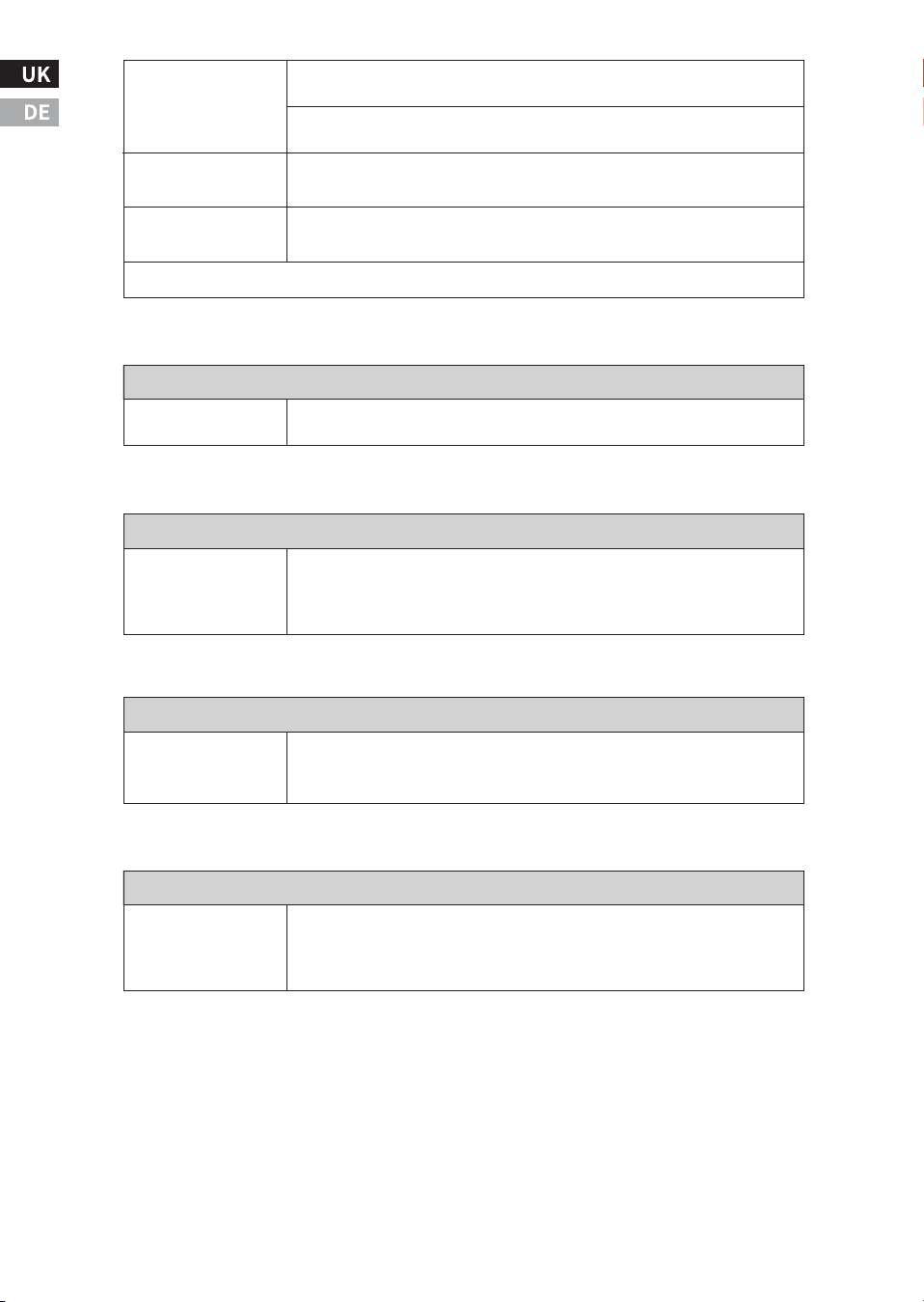
d) Alarm Function
-��-
F��
��.�
Battery Under Voltage Recovery selectable range: ��.� - ��.�V (�.�V
step)(Default ��.�V)
The Battery Low Recovery Voltage has to be with a minimum of �.�V
above the Battery Low Alarm(F��) Voltage.
��.�V (Not User selectable)
��.�V(Not User selectable)
Battery Over Voltage
Disconnect
Battery Over Voltage
Recovery
Note: For ��Vsystem, all voltages are doubled.
Alarm Setting
F��
Fault and warning audible alarm can be enabled (On-Default) or
disabled(Off).
e) Power Saving Shutdown Time Setting Function
Power Saving Shutdown Time setting
F��
Power Saving Shutdown Time function can be enabled (ON) or
disabled (OFFDefault).The range is from � to ��, adjusted by �-h
increments. The next setting after �� is OFF. The shutdown time will be
calculated when the total load is less than ��W
g) AC Qutput Voltage Function
AC Output Voltage Function Setting
F��
���V Series Output Voltage Range: ���v,���V,���V; (Default ���V)
���V Series Output Voltage Range: ���V,���V,���V; (Default ���V)
Note: After changing the output voltage setting, turn the unit off and
then on again, in order for the change to take effect.
f) AC Output Frequency ��HZ or ��HZ Function
Qutput Frequency ��HZ or ��HZ Function Setting
F��
Output Frequency ��HZ or ��HZ Function SettingNote: After changing
the output frequency setting, turn the unit off and then on again, in
order for the change to take effect.
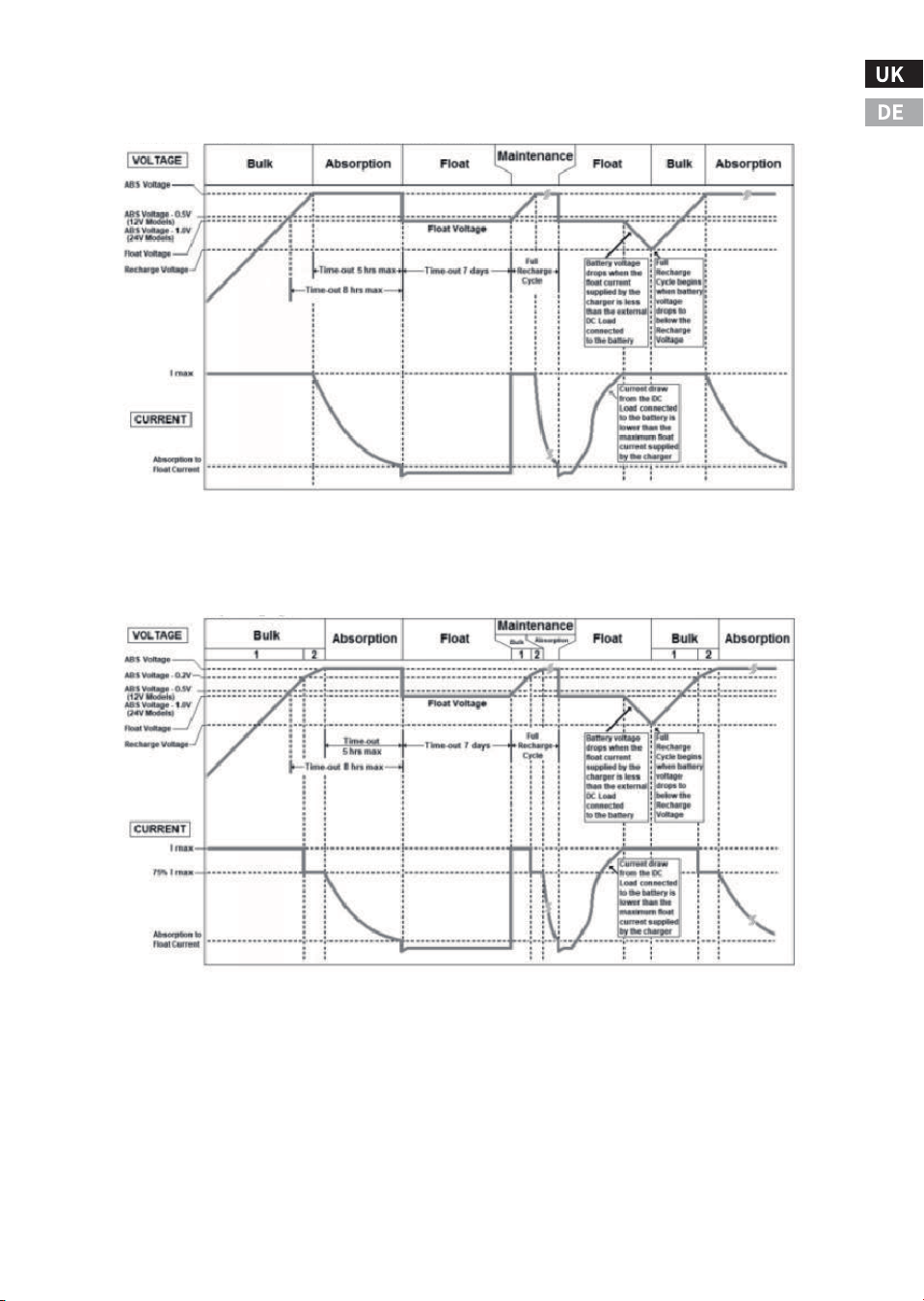
h) Charger Functions
GEL, AGM, Flooded and Program Battery Charging Profile
Lithium Battery Charging Profile
Battery Charging Cycle
-��-
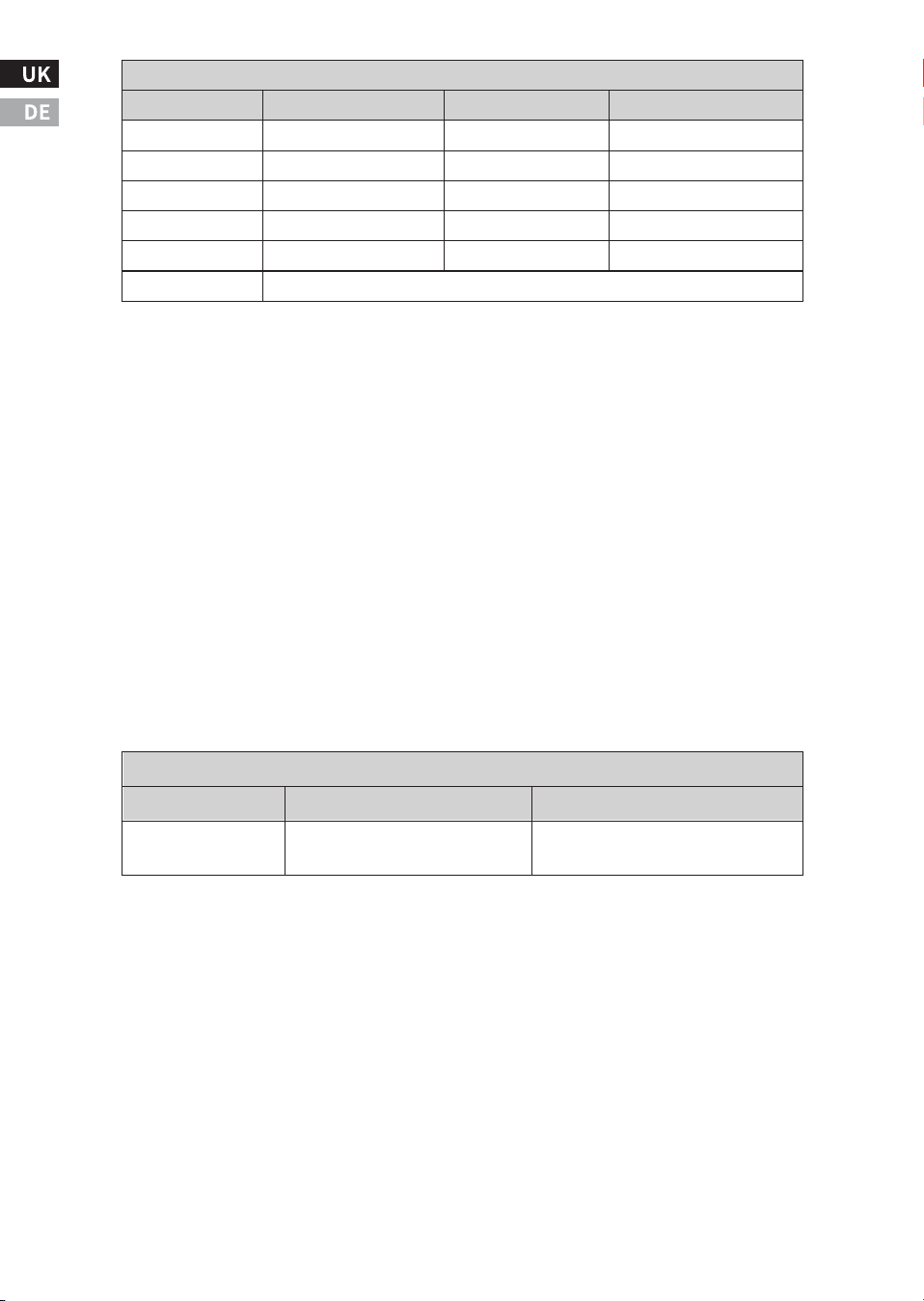
* Consult the battery manufacturer when choosing the Bulk and Float
Voltage for the battery bank.
* When selecting the Float Voltage, it has to be with a minimum of
�.�V below Bulk Voltage setting.
* The Recharged Voltage determines the restart cycle of the battery
bank. The charger will go through a full recharge cycle when the
battery voltage drops to the Recharge Voltage set value.
When selecting the Recharge Voltage, it has to be with a minimum of
�.�V below the Float Voltage setting.
* If Power Supply is chosen, the charger will provide a constant
voltage to charge the battery bank.
Note: For ��V system, all voltages are doubled.
* Consult the battery manufacturer when choosing the Bulk Stage
charging current of the battery bank. For a sealed lead acid battery,
the rule of thumb for the maximum charging current is �/� of battery
capacity.
* The Absorption to Float Stage current determines the transition
from Absorption Stage to Float Stage. If an external DC load is
connected to the battery bank, a higher current setting is recom-
mended to compensate for the extra current drawn from the external
DC load.
-��-
Charging Voltage Setting: Bulk/Absorption (ABS), Float (FLO) and Recharge (REC)
Bulk Voltage (Default)
��.�-��.�V (��.�V)
��.�-��.� & ��.�V(��.�V)
��.�-��.�V (��.�V)
��.�-��.�V(��.�V)
��.�-��.�V(��.�V)
Float Voltage (Default)
��.�-��.�V (��.�V)
��.�-��.�V (��.�V)
��.�-��.�V (��.�V)
��.�-��.�V (��.�V)
��.�-��.�V (��.�V)
��.�-��.�V (��.�V)
Recharge Voltage (Default)
��.�-��.� V(��.�V)
��.�-��.� V (��.�V)
��.�-��.� V (��.�V)
��.�-��.�V(��.�V)
��.�-��.� V(��.�V)
Battery Type
GEL
Flooded
AGM
Lithium
Program
Power Supply
Charging Current Setting: Bulk Stage (F��), Absorption to Float Stage (F��)
Model
��V ����W
Bulk Stage
���A,��A,��A,��A,��A
(Default: ���A) (Default: ��A)
Absorption to Float Stage
��A,��A,��A,�A,�A
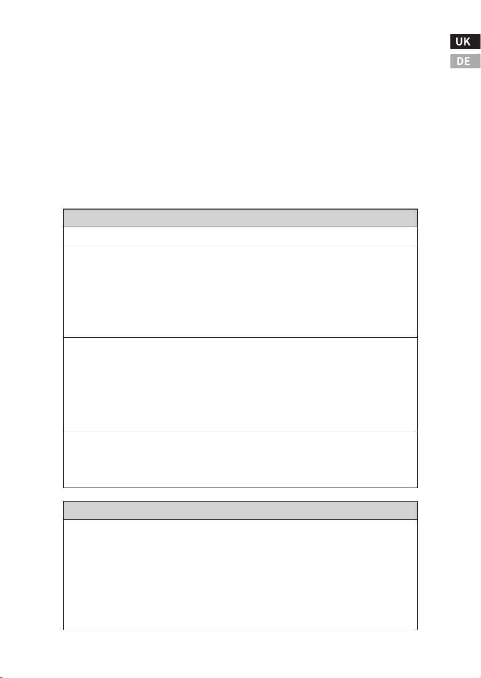
* In order to avoid the tripping of the external AC Source Branch
Breaker, when high powered AC loads are connected to the AC
Output, the charging current will automatically be reduced so that
the total AC Input current (AC Output Current + AC Charger Current) is
maintained below the set values of the AC Input Circuit Breaker (F��).
See more details on AC Source Circuit Breaker Function.
Note: When the battery charging process starts, the unit will first
measure the battery voltage. If it senses the battery voltage is below
�.�V, the charger current will automatically reduce to < ��A. It will
resume back to the set charger current when the battery is charged to
above �.�V in �� minutes. See more details on section Understanding
the Error Codes(E�� and E��)
-��-
There are three settings (Low, Normal, High) available for battery temperature setting.
* Setting to 'Low'temperature will compensate the charging voltage by +�.���V on GEL
andFlooded battery type and +�.���V on AGM battery type.
Setting to 'Nor' will have no change to the selected charging voltage.
* Setting to 'Hi’ temperature will compensate the charging voltage by -�.��V on GEl and
Flooded battery type and -�.��V on AGM battery type.
Optional Battery Temperature Sensor (BTS) installed (Part Number: BTS��K).
* lf the temperature measured by the BTS is below ��°C, the charging voltage will be
compensated with +�.���V per °C on GEL and Flooded battery or +�.���V per °C on AGM
battery.
* lf the temperature measured by the BTS is above ��c, the charging voltage will be compen-
sated with -�.���V per °C on GEL and Flooded battery or -�.���V per °C on AGM battery.
There is no voltage adjustment compensation when battery type of Lithium, Program or
Power Supplyis selected.
Note:For ��V system, allvoltage values ues are doubled.
Battery Temperature Setting 'F��' (voltage adjustment from ��°C setting)
No Battery Temperature Sensor(BTS) installed
Equalization setting can only be set on Flooded batteries. Before the equalization begins, the
unit will automatically fully charge the battery first, followed by one hour of equalization.
Consult and follow the instruction provided by the battery manufacturer when performing
the equalization process.
* Select 'F��'under setting �H.
* The unit will start a full flooded battery charging cycle first before the Equalization begins.
The Equalization Voltage is set to ��.�V and current is limited to �/�� of the set Bulk Stage
ChargingCurrent.
Flooded Battery Equalization(F��)Setting:
i) AC Source Circuit Breaker Function
-��-
This setting limits the total AC current draw from the AC Source during the ByPass Mode to
avoid tripping the AC Source Circuit Breaker . The selected value has to be the same or
smaller than the rating of the AC Source Circuit Breaker.
AC Source Circuit Breaker Setting
���VACModels:Selectable Values: ��A,��A,��A(Default: ��A)F��
Equalization setting can only be set on Flooded batteries. Before the equalization begins, the
unit will automatically fully charge the battery first, followed by one hour of equalization.
Consult and follow the instruction provided by the battery manufacturer when performing
the equalization process.
* Select 'F��'under setting �H.
* The unit will start a full flooded battery charging cycle first before the Equalization begins.
The Equalization Voltage is set to ��.�V and current is limited to �/�� of the set Bulk Stage
Charging Current.
* Display will show 'F��' and the battery voltage during the Equalization period.
The unit cannot determine when to terminate the equalization of the battery. A one-hour
timeout is set as a safety feature and requires the user to continually re-activate it as
necessary after checking the batteries manually.
* To terminate the Equalization process, change and save the battery type to other types like
AGM, GEL etc.and then change and save it back to the Flooded type battery.
Note:For ��V system,all voltage values are doubled.
Flooded Battery Equalization(F��)Setting:
The charger will restart a full charging cycle automatically if the float stage is maintained for �
days.
Battery Recharge Timer:
* Display will show 'F��' and the battery voltage during the Equalization period.
* The unit cannot determine when to terminate the equalization of the battery. A one-hour
timeout is set as a safety feature and requires the user to continually re-activate it as
necessary after checking the batteries manually.
* To terminate the Equalization process, change and save the battery type to other types like
AGM, GEL etc.and then change and save it back to the Flooded type battery.
Note:For ��V system,all voltage values are doubled.
j) Manufacturing Factory Default Function
k)Understanding of Ignition Start ON/OFF Function
Providing +��V to the Ignition Start port will turn ON the inverter and
removing the +��V will turn OFF the inverter.
Use of the 'Ignition Start' port located on the main unit will override
the 'Power' On/Off function of both the Multi-Function Display and
the main unit.
AC Load on Inverter
Although the Inverter-Charger can provide high surge power up to
two times the rated output power, some high surge loads like air
conditioners, sump-pumps, heavy-duty motors, etc. may still trigger
the inverter protection system even though the load falls within the
power rating of the inverter. A higher power Inverter-Charger is
required for these appliances.
Understanding the Error Codes
-��-
Note: E�� will show for about �� sec. After �� sec, display will turn Off and
unit will shutdowncompletely.
Note: The charger current with battery voltage < �.�V is limited to ~ ��A and
there is a �� minutes timer to allow the charger to charge the battery to > �.
�V, lf battery voltage remains < �.�V aftel �� minutes ofcharging, the charger
will shutdown and show E�� (Bad battery).
Note: The setting for battery type is GEL. lf another battery type is used, select 'Yes' to set all
the parameter to factory default, then proceed to the battery type and make change to the
new battery type.
Factory Default Setting
Code Condition Corrective Action
Select 'Yes' to reset all the settings to the preset Factory Default settings.
F�� NO
E��
(Battery
Mode)
E��
(Bypass
Mode)
Recharge the battery immediately
and restart unit.
No AC Output. Inverter shutdown due
to low battery voltage.
Check the battery connection.No battery is connected to the unit.
Remove or turn off Dc load connected
to the battery to minimize the
charging time to charge the battery to
>�.�V, lf this condition is iqnored the
charger will terminate the charging
process(See note below).
Battery voltage remains < �.�V. A
large portion of the charger current
provided is used to maintain the DC
load connected to the battery. E��
will turn OFF when the battery
voltage is charged to > �.�V
-��-
Note: E�� will show for about �� sec. After �� sec, display will turn off and unit
will shutdown completely.
Code Condition Corrective Action
E��
E��
E��
Check battery voltage or determine if
any external charger is connected to
the battery bank that leads to high
battery voltage.
When unit is in Battery/Inverter
mode, unit senses the battery voltage
is too high and inverter has
shutdown.
Check load connected to the output.
Reduce load and restart the unit.
When unit is in Battery/Inverter
mode, AC output is overloaded or
short-circuited andinverter has
shutdown.
Turn unit off and wait for �� minutes
before restarting.Check if any object
has blocked the airflow of the unit.
When unit is in Battery/Inverter
mode. internal temperature is too
high and inverter has shutdown.
E��
Recharge battery as unit will
shutdown shortly.
When unit is in Battery/Inverter
mode, input battery voltage is low
and warning occurs.
E��
Reduce AC load.
Note:E�� occurs when AC Output power
is close to ����W for ����W unit, ����W
for ����W uniand ����W for ����W unit.
When unit is in Battery/Inverter
mode, AC output load connected has
been sensed high and is close to
shutdown limit.
E��
Reduce load and check if any
ventilation of theunit is blocked.
When unit is in Battery/Inverter
mode, internal temperature is high
and is close to over-temperature
shutdown limit.
E��
Check battery setting. And check if
there is any other DC power sources
connected to the battery has high
voltage.
When unit is in Bypass mode, Battery
Charging voltage is too high.
E��
-Check corrective action in E��
(Bypass Mode)and restart the
charging process by removing and
reconnecting the AC Input Source.
Bad Battery Classification (Bypass
Mode)condition has not been solved.
AC Charge!has shutdown.
-Check if there is any heavy DC load
connected tothe battery as stated in
E��(Bypass mode).
-Restart the charging process.
-Change to a new battery.
Other conditions leading to Bad
Battery Classification: Battery Voltage
remains below �/�/�.�V after �/�/��
minutes of charging.
E��
Reduce load and check if any
ventilation of the unit is blocked.
When unit is in Bypass mode, interna
transfer switch temperature is high
and shutdown occurs.
-��-
Code Condition Corrective Action
E��
E��
E��
(optional)
E��
(optional)
Check RJ�� cable connected between
the main unit and the remote display
panel.
Remote display panel has communi-
cation error.
Check AC Input and AC Output wiring.AC Back Feed to Unit AC Output.
E��
Consult Customer Service for assistance.
Internal Fault. Unit damage.
Reduce AC load.Check the AC Circuit
Breaker(Cbr)rating match with the
external AC Input Source Branch
Breaker rating.
AC Input Current withdrawn from the
unit is close to the set AC Circuit
Breaker (Cbr) rating.
Reduce AC Load connected to unit.
AC Input Current drawn by unit is
beyond the current rating of the
transfer switch(��A for ���V
models;��A for ���V models).
E��
Cool down the battery. Battery
charging cycle will automatically
resume when the temperature drops
to below �� ℃.
Battery temperature sensed by BTS
is>��°C. Battery charging cycle
terminates.
E��
Check battery and environmental
temperature or add ventilation to the
battery compartment.
Battery temperature sensed by BTS
is>�� °C and is close to battery
temperature thermal shutdown.
E��
Check battery and environmental
temperature.The charging cycle will
resume when temperature increases
to > � °C.
Battery temperature sensed by BTS
is<� °C. Battery charging cycle
terminates.
To troubleshoot the unit, please note the error code displayed on the
main unit and review ‘Understanding the Error Codes ’in section �.
-��-
VII. Troubleshooting
Problem Possible Cause/Condition Solution
No AC
Output at
AC Output
Socket
Reset the thermal breaker.
The thermal breaker on the unit is
tripped.
Chec kunit 'Int' setting.Unit is set to Inverter Off.
Reduce AC load.Inverter may be
overloaded.
Check Error code on display. Inverter
may be overloaded.
Reset GFCl.
For ���V model, GFCl may have
tripped.
Check AC Input Source. Operating
range of AC Input is ��-���VAC. Unit
Start-upAC Voltage is higher than ��V
AC and below ���VAC.
With unit running from AC Input
Source or shore power, the Ac input
Source is available but is outside the
acceptance range.
Check battery voltage.
DC over-voltage,under-voltage, or
other shutdown type errors in
addition to overload.
Set Charger function 'CHG' to On.
Check charger setting. Charger may
be set to Off.
Check battery and remove the DC
load connected to the battery and
restart the charger again.
Unit had determined the battery is
bad. See also description in Error
code E��(Bypass Mode) and E��.
Charger did
not supply
charging
current
Check battery temperature or
environmental temperature. Battery
charging cycle will resume when the
battery cools down to acceptable
level. See Understanding the Error
Codes for more details.
Battery is with BTS installed and it
senses the battery temperature is
high (E��).
Check battery temperature or
environmental temperature. Battery
charging cycle will resume when the
battery temperature increases to
acceptable temperature. See
Understanding the Error Codes for
more details.
Battery is with BTS installed and it
sense! the battery temperature is too
low to accept charge (E��).
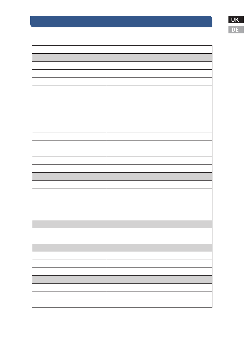
VIII. Specification
-��-
��V Input Model
Specification
Running as Inverter
AC Output Power
AC Output Current
AC Surge Power (Peak)
AC Output Voltage/Frequency
AC Output Waveform
Nominal DC Input Voltage
No Load battery draw(Inverter Mode)
No Load Current(Power Saving Mode)
DC Input Valtage operating range
Under Voltage Alarm
Under Voltage Alarm Recovery
Under Voltage Shutdown
Under Voltage Recovery
Over Voltage Shutdown /Recovery
AC Transfer Switch
Transfer Time
Transfer Relay Rating
AC Input Source Setting (Optional)
AC Output Hardwire (Max.)
AC Output Socket (Max.)
Display
Inverter Mode
Charger Mode
Remote PANEL Display
Remote Display Port
Inverter Mode
Charger Mode
Running as Battery Charger
Charging Voltage Range
Float Voltage Range
Recharge Voltage Range
���VAC ��V Model
����W
��A
����W
��VAC/��HZ
Sinewave (<�% THD)
��.� VDC
<�.� ADC
< �.� ADC
��.�-��.� VDC
��.� - ��.� VDC
��.�-��.� VDC
��.�-��.� VDC
��.� - ��.� VDC
��.� / ��.� VDC
< �� ms
��A
��, ��, ��A
��A
GFCI ��A
Battery Voltage, DC Current, AC Output Power
Charging Voltage, Charging Current, AC Input Power
RJ��
Battery Voltage, DC Current, AC Output Power
Charging Voltage, Charging Current, AC Input Power
��.� - ��.� VDC
��.� -��.� VDC
��.� - ��.� VDC
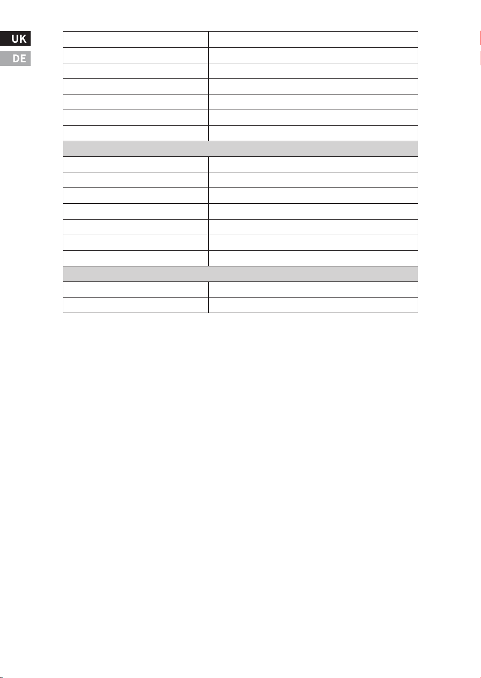
-��-
Note: Specifications are subject to change without notices
Bulk Charge CurrentRange
Absorption -Float Current Range
Battery Type
Charge Cycle Stages
Maintenance RechargeCycle
Power Factor Correction
Efficiency
Safety and Environmental
Conformance
EMIEMC
Agency Markings
Operating Temperature
Storage Temperature
Relative Humidity
Operating Altitude
Weight and Dimension
Weight
Dimension
�� -��� A
�-�� A
Gel, Flooded, AGM, Lithium, Program, Power Supply
Buk /Absorption / Float / Recharge
� days
>��%
>��%
���VAC Series
UL ���, CSA C��.� No.���.�-��
FCC Part �� Class B
CETLUS
�'C to ��°C (��°F to ���°F)
-��°C to ��°C (-�°F to ���°F)
�-��% non-condensing
Up to �,���ft (����m) above sea level
��.� lbs.(�.� kg)
��.� x��.� x�.� inches (���.�x��� x���mm)

IX. Warrant
During the production and assembly of the Inverter-Charger, each
unit undergoes several checks and tests. These are carried out with
strict adherence to the established procedures. Each Inverter-Char-
ger has a serial number allowing complete follow-up on the checks,
according to the particular data for each device. For this reason it is
very important never to remove the type plate which shows the serial
number. The warranty for this equipment depends upon the strict
application of the instructions appearing in this manual.
When the product is operated under normal conditions, we will
provide Two Years of dependable service.
Two-year Limited Warranty
We warrant the inverter-charger to be free from the defects and/or
failures specified below for a period not exceeding two years from the
date of sale to the original customer.
* Defects and/or failures due to manufacturing
* Defects and/or failures due to materials
* Non-conformity to specifications due to faulty manufacturing
and/or inspection processes. If the inverter-charger fails to conform
to this warranty, we will repair or replace the inverter-charger at our
sole option.
-��-

Warranty Exclusions
�. No claim based on the limited warranty will be brought after the
applicable warranty period. Any delivery of additional inverter or the
repair or replacement of the inverter would not extend the original
terms of this limited Warranty.
�. This Limited Warranty shall not cover defects and/or failures of the
inverter from the following causes even though such defects and/or
failures are discovered within the applicable warranty period.
a) Defects and/or failures caused by devices and/or parts other than
the inverter or by mounting methods of such devices and/or parts.
b) Defects and/or failures caused by defective wiring, installation, or
handling.
c) Defects and/or failures caused by installations not in conformance
with inverter specifications, installation manuals, operation manu-
als, or labels attached to the inverter.
d) Defects and/or failures caused by unauthorized maintenance,
operation or modification.
e) Defects and/or failures caused by removal from the original place
of installment.
f) Defects and/or failures caused by repair not in accordance with our
instructions.
g)Defects and/or failures caused by in appropriate handling during
transportation or storage.
h)Defects and/or failures caused by external accidents such as fire,
explosion, and civil disorder.
i) Defects and/or failures caused by natural forces, acts of God or force
majeure events and other unforeseen hurricanes, tornadoes, volca-
nic action, floods, tsunami, lightning, snow dangers, etc
j) Defects and/or failures caused by smoke and/or other pollution, salt
damage, acid rain, etc.
We reserve the rights to make any modifications to the product with-
out prior notification.
-��-
VIII. Technical Support
-��-
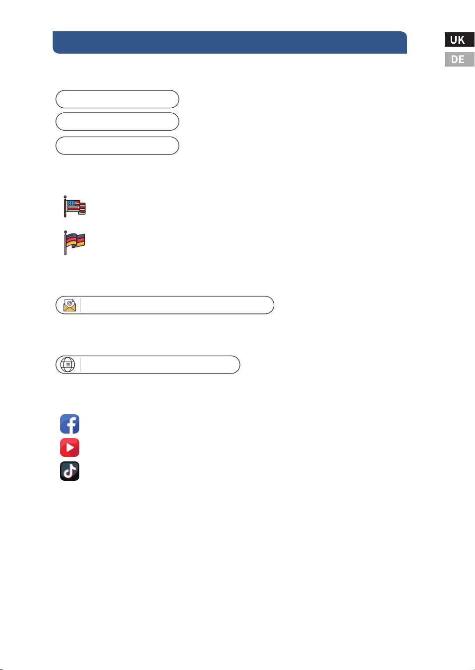
7.Renoly Support
Address(US): ���� East State Hwy D Suite C Springfield,
Address(DE):
Missouri �����
ECO-Worthy Europe GmbH Otto-Hahn-Str. ��
����� Friedrichsdorf - Köppern Germany
Youtube: @ecoworthy
Facebook: https://www.facebook.com/ecoworthy.store/
Tiktok: https://www.tiktok.com/@eco_worthy
�) Customer service telephone numbers:
�) Customer service email:
Tel(DE): +�� ����-����-���
Tel(US): �-���-���-����
Tel(UK): +���-���-������
�) Company address: USA/Germany
E-mail:customer. service@eco-worthy.com
�) Official website address:
Web: https://www.eco-worthy.com/
�) Official social media:

ECO-WORTHY