3.5KW SOLAR OFF-GRID INVERTER
All-in-one
ECO3500W(SR)
SUPPORT
If
you are experiencing technical problems and cannot find a solution
in this manual,please contact ECO-WORTHY for further assistance.
·Call:1-866 939 8222(US&CA)
+49 6175 6514 999(DE)
·Web://www.eco-worthy.com/
·E-mail: customer.service@eco-worthy.com
+44 7553 406988(UK)
USER MANUAL
Version: 1.0

All-in-one solar charge inverter V4.1 2
Important safety instructions
Please keep this manual for future use.
This manual contains all safety, installation and operating instructions for the ECO Series all-in-one solar
charge inverter.
Please read all instructions and precautions in the manual carefully before installation and use.
Non-safety voltage exists inside the all-in-one solar charge inverter. To avoid personal injury, users shall
not disassemble the all-in-one solar charge inverter themselves. Contact our professional maintenance
personnel if there is a need for repair.
Do not place the all-in-one solar charge inverter within the reach of children.
Do not install the all-in-one solar charge inverter in harsh environments such as moist, oily, flammable
or explosive, or heavily dusty areas.
The mains input and AC output are high voltage, so please do not touch the wiring terminals.
The housing of the all-in-one solar charge inverter is hot when it is working. Do not touch it.
Do not open the terminal protective cover when the all-in-one solar charge inverter is working.
It is recommended to attach proper fuse or circuit breaker to the outside of the all-in-one solar charge
inverter.
Always disconnect the fuse or circuit breaker near the terminals of PV array, mains and battery before
installing and adjusting the wiring of the all-in-one solar charge inverter.
After installation, check that all wire connections are tight to avoid heat accumulation due to poor
connection, which is dangerous.
The all-in-one solar charge inverter is off-grid. It is necessary to confirm that it is the only input device
for load, and it is forbidden to use it in parallel with other input AC power to avoid damage.

All-in-one solar charge inverter V4.1
3
CONTENTS
1. GENERAL INFORMATION............................................................................. 4
1.1 PRODUCT OVERVIEW AND FEATURES ......................................................................... 4
1.2 BASIC SYSTEM INTRODUCTION................................................................................... 5
1.3 APPEARANCE .................................................................................................................5
1.4 DIMENSION DRAWING .................................................................................................7
2. INSTALLATION INSTRUCTIONS................................................................... 8
2.1 I
NSTALLATION PRECAUTIONS
...................................................................................... 8
2.2 W
IRING SPECIFICATIONS AND CIRCUIT BREAKER SELECTION
................................... 9
2.3 I
NSTALLATION AND WIRING
......................................................................................10
2.4 I
NSTALLATION AND WIRING
......................................................................................15
2.4.1 INTRODUCTION .....................................................................................................15
2.4.2 PRECAUTIONS FOR CONNECTING THE PARALLEL CONNECTING LINES ............16
2.4.3 SCHEMATIC DIAGRAM OF PARALLEL CONNECTION IN SINGLE PHASE .............18
2.4.4 SCHEMATIC DIAGRAM OF PARALLEL CONNECTION IN SPILIT PHASE ...............21
3. OPERATING MODES .................................................................................... 31
3.1 CHARGING MODE ...................................................................................................... 31
3.2 OUTPUT MODE ...........................................................................................................32
4. LCD SCREEN OPERATING INSTRUCTIONS ................................................33
4.1 O
PERATION AND DISPLAY PANEL
............................................................................ 33
4.2 S
ETUP PARAMETERS DESCRIPTION
...........................................................................37
4.3 B
ATTERY TYPE PARAMETERS
.....................................................................................45
5. OTHER FUNCTIONS ..................................................................................... 46
5.1 DRY NODE .................................................................................................................. 47
5.2 RS485 COMMUNICATION PORT .............................................................................. 47
5.3 USB COMMUNICATION PORT ...................................................................................47
5.4 PARALLEL COMMUNICATION FUNCTION (PARALLEL OPERATION ONLY).............. 48
5.5 CURRENT SHARING DETECTION FUNCTION (PARALLEL OPERATION ONLY) .........48
6. PROTECTION ................................................................................................49
6.1 PROTECTIONS PROVIDED ...........................................................................................49
6.2 F
AULT CODE
............................................................................................................... 51
6.3 H
ANDLING MEASURES FOR PART OF FAULTS
..........................................................55
7. SYSTEM MAINTENANCE ............................................................................ 56

All-in-one solar charge inverter V4.1
4
8. TECHNICAL PARAMETERS ......................................................................... 57
1. General information
1.1 Product overview and features
ECO series is a new all-in-one hybrid solar charge inverter, which integrates solar energy storage &
means charging energy storage and AC sine wave output. Thanks to DSP control and advanced control
algorithm, it has high response speed, high reliability and high industrial standard. Four charging modes are
optional, i.e. Only Solar, Mains Priority, Solar Priority and Mains & Solar hybrid charging; and two output
modes are available, i.e. Inverter and Mains, to meet different application requirements.
The solar charging module applies the latest optimized MPPT technology to quickly track the maximum
power point of the PV array in any environment and obtain the maximum energy of the solar panel in real
time.
Through a state of the art control algorithm, the AC-DC charging module realizes fully digital voltage
and current double closed loop control, with high control precision in a small volume. Wide AC voltage
input range and complete input/output protections are designed for stable and reliable battery charging
and protection.
Based on full-digital intelligent design, the DC-AC inverter module employs advanced SPWM
technology and outputs pure sine wave to convert DC into AC. It is ideal for AC loads such as household
appliances, power tools, industrial equipment, and electronic audio and video equipment. The product
comes with a segment LCD display design which allows real-time display of the operating data and status of
the system. Comprehensive electronic protections keep the entire system safer and more stable.
Features:
1. Full digital voltage and current double closed loop control, advanced SPWM technology, output of
pure sine wave.
2. Two output modes: mains bypass and inverter output; uninterrupted power supply.
3. Available in 4 charging modes: Only Solar, Mains Priority, Solar Priority and Mains & Solar hybrid
charging.
4. Advanced MPPT technology with an efficiency of 99.9%.
5. Designed with a LCD screen and 3 LED indicators for dynamic display of system data and
operating status.
6. ON/OFF rocker switch for AC output control.
7. Power saving mode available to reduce no-load loss.
8. Intelligent variable speed fan to efficiently dissipate heat and extend system life.
9. Lithium battery activation by PV solar or mains, allowing access of lead-acid battery and lithium
battery.
10. 360 ° all-round protection with a number of protection functions.
All-in-one solar charge inverter V4.1
5
11. Complete protections, including short circuit protection, over voltage and under voltage
protection, overload protection, reverse protection, etc.
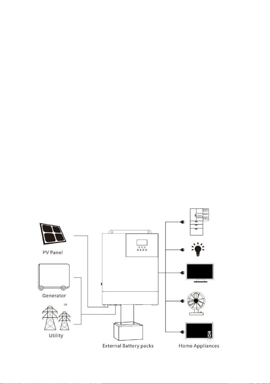
1.2 Basic system introduction
The figure below shows the system application scenario of this product. A complete system consists of the
following parts:
1. PV module: Convert light energy into DC power, and charge the battery through the all-in-one solar
charge inverter, or directly invert into AC power to drive the load.
2. Mains or generator: Connected at the AC input, to power the load while charging the battery. If the
mains or generator is not connected, the system can also operate normally, and the load is powered by the
battery and PV module.
3. Battery: Provided to ensure normal power supply to the system loads when solar energy is
insufficient and the Mains is not connected.
4. Household load: Allow connection of various household and office loads, including refrigerators,
lamps, TVs, fans and air conditioners.
5. All-in-one solar charge inverter: The energy conversion unit of the whole system.
Specific system wiring method depends on the actual application scenario.
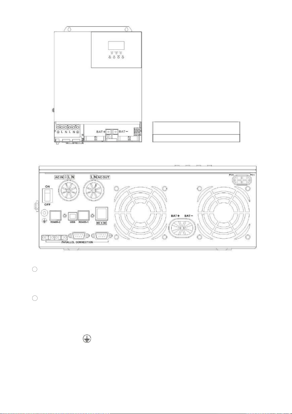
1.3 Appearance

All-in-one solar charge inverter V4.1
6
①
Overload protector
⑩
RS485-1
communication port
②
ON/OFF rocker switch
⑪
Dry contact port
③
AC input port
⑫
Cooling fan
④
AC output port
⑬
Battery port
⑤
Grounding screw hold
⑭
Cooling fan
⑥
RS485-2 communication port
⑮
PV port
⑦
Current sharing port
(parallel module only)
⑯
Touch the key lightly
⑧
Parallel communication port
(parallel module only)
⑰
Indicator light
⑨
USB communication port
⑱
LCD screen
All-in-one solar charge inverter V4.1
7
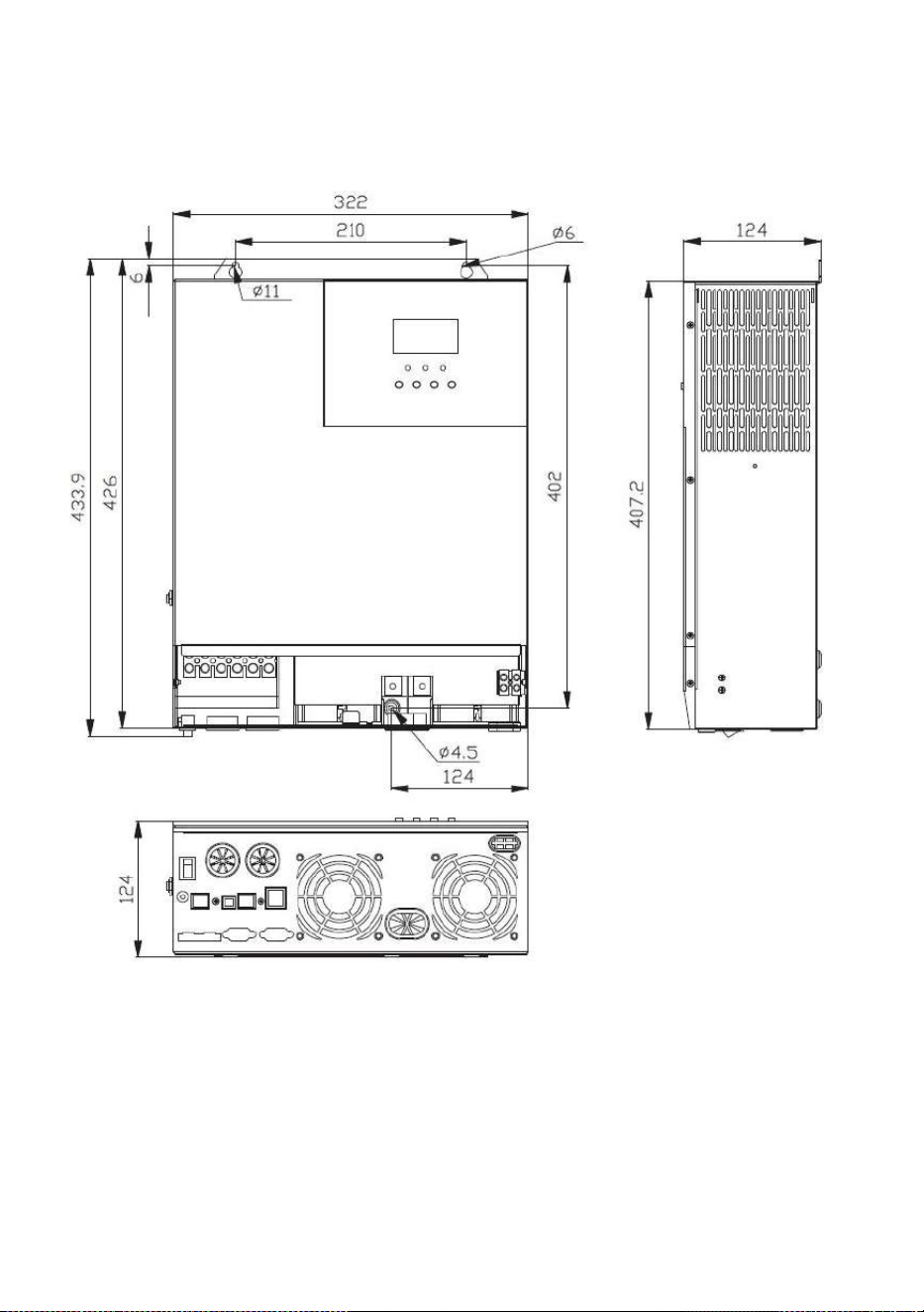
1.4 Dimension drawing

All-in-one solar charge inverter V4.1 8
2. Installation instructions
2.1 Installation precautions
Please read this manual carefully prior to installation to familiarize yourself with the installation
steps.
Be very careful when installing the battery. Wear safety goggles when installing a lead-acid liquid
battery. Once coming into contact with the battery acid, rinse with clean water timely.
Do not place metal objects near the battery to prevent short-circuit of the battery.
Acid gas may be generated when the battery is charged. So, please ensure good ventilation.
When installing the cabinet, be sure to leave enough space around the all-in-one solar charge
inverter for heat dissipation. Do not install the all-in-one solar charge inverter and lead-acid
battery in the same cabinet to avoid corrosion by acid gas generated during battery operation.
Only the battery that meets the requirements of the all-in-one unit can be charged.
Poorly connected connections and corroded wires may cause great heat which will melt the wire
insulation, burn the surrounding materials, and even cause fires. So, make sure the connectors
have been tightened, and the wires are secured with ties to avoid looseness of connections
caused by shaking of wires during mobile application.
The system connection wires are selected according to a current density of not more than 5
A/mm
2
.
Avoid direct sunlight and rainwater infiltration for outdoor installation.
Even after the power is turned off, there is still high voltage inside the unit. Do not open or touch
the internal components, and avoid related operations until the capacitor completely discharges.
Do not install the all-in-one solar charge inverter in harsh environments such as moist, oily,
flammable or explosive, or heavily dusty areas.
Polarity at the battery input end of this product shall not be reversed, otherwise it may damage
the device or cause unpredictable danger.
The mains input and AC output are high voltage, so please do not touch the wiring terminals.
When the fan is working, do not touch it to prevent injury.
Load equipment input power needs to confirm that this all-in-one solar charge inverter is the
only input device, and it is forbidden to use in parallel with other input AC power to avoid
damage. It is necessary to confirm that the solar charge inverter is the only input device for load

All-in-one solar charge inverter V4.1 9
equipment, and it is forbidden to use it in parallel with other input AC power to avoid damage.
2.2 Wiring specifications and circuit breaker selection
Wiring and installation must comply with national and local electrical codes.
Recommended PV array wiring specifications and circuit breaker selection: Since the output current of the
PV array is affected by the type, connection method and illumination angle of the PV module, the minimum
wire diameter of the PV array is calculated according to its short-circuit current; refer to the short-circuit
current value in the PV module specification (the short-circuit current is constant when the PV modules are
connected in series; the short-circuit current is the sum of the short-circuit currents of all PV modules
connected in parallel); the short-circuit current of the PV array shall not exceed the maximum input current.
Refer to the table below for PV input wire diameter and switch:
Models
Recommended PV
wiring diameter
Maximum PV
input current
Recommended air switch or
circuit breaker type
110/120Vac
10mm
2
/7AWG
50A
2P—63A
Note: The voltage in series shall not exceed the maximum PV input open circuit voltage.
Refer to the table below for recommended AC input wire diameter and switch:
Models
Recommended AC
input wiring diameter
Maximum
bypass input
current
Recommended air switch or
circuit breaker type
110/120Vac
10mm
2
/7AWG
40A
2P—40A
Note: There is already an appropriate circuit breaker at the Mains input wiring terminal, so it is not
necessary to add one more.
Recommended battery input wire diameter and switch selection
Models
Recommended
battery wiring
diameter
Rated
battery
discharge
current
Maximum
charge
current
Recommended air
switch or circuit
breaker type
110/120Vac
25mm
2
/3AWG
85A
120A
2P—140A
Recommended AC output wiring specifications and circuit breaker selection
All-in-one solar charge inverter V4.1
1 0
Models
Recommended
AC output
wiring
diameter
Rated inverter
AC output
current
Maximum
bypass output
current
Recommended air
switch or circuit
breaker type
110/120Vac
10mm
2
/7AW
30A
40A
2P—40A
Note: The wiring diameter is for reference only. If the distance between the PV array and the all-in-one
solar charge inverter or the distance between the all-in-one solar charge inverter and the battery is
relatively long, using a thicker wire can reduce the voltage drop to improve system performance.
Note: The above are only recommended wiring diameter and circuit breaker. Please select the appropriate
wiring diameter and circuit breaker according to actual situations.
2.3 Installation and wiring
Installation steps::
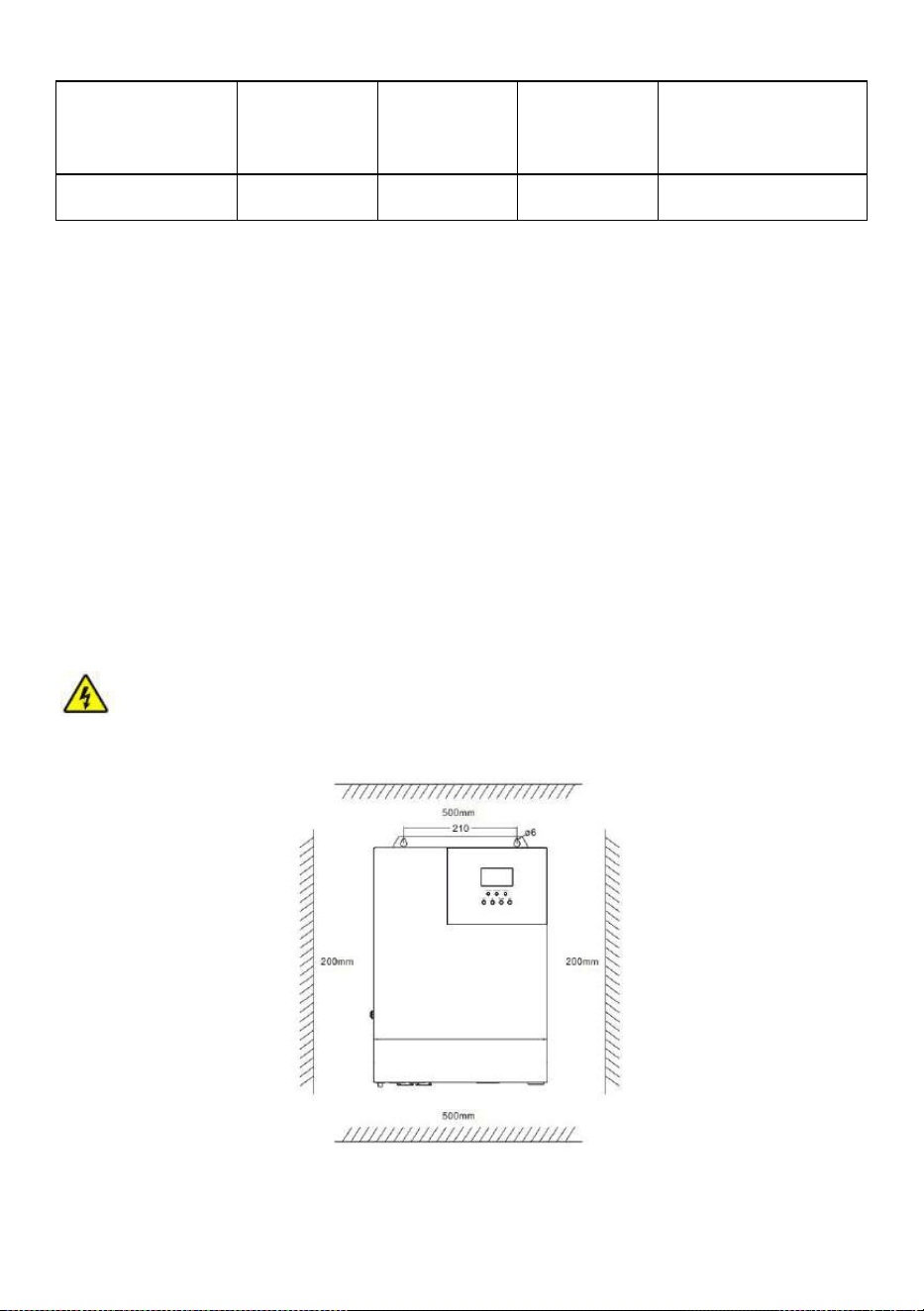
Step 1: Determine the installation position and the space for heat dissipation. Determine the installation
position of the all-in-one solar charge inverter, such as wall surface; when installing the all-in-one solar
charge inverter, ensure that there is enough air flowing through the heat sink, and space of at least 200m to
the left and right air outlets of the inverter shall be left to ensure natural convection heat dissipation. Refer
to the installation diagram of the whole machine as above.
Warning:
Danger of explosion! Never install the all-in-one solar charge inverter and lead-acid
battery in the same confined space! Also do not install in a confined place where battery gas may collect.
Step 2:
Remove the terminal cover
All-in-one solar charge inverter V4.1
1 1
Step3:
Wiring
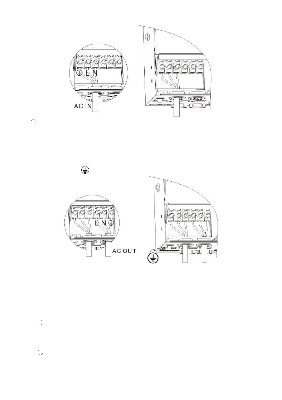
AC input / output wiring method:
1 Prior to AC input/output wiring, disconnect the external circuit breaker and confirm that the wire
used is thick enough. Please refer to Section 2.2 “ Wiring Specifications and Circuit Breaker
Selection”;
2 Properly connect the AC input wire according to the wire sequence and terminal position shown
in the figure below. Please connect the ground wire first, and then the live wire and the neutral
wire;
:Ground L:Live N:Neutral
All-in-one solar charge inverter V4.1
1 2
3 Properly connect the AC output wire according to the wire sequence and terminal position
shown in the figure below. Please connect the ground wire first, and then the live wire and the
neutral wire. The ground wire is connected to the grounding screw hole on the cabinet through
the O-type terminal.
:Ground L:Live N:Neutral
Note: The grounding wire shall be as thick as possible (cross-sectional area is not less than 4mm
2
).
The grounding point shall be as close as possible to the all-in-one solar charge inverter. The shorter
the grounding wire, the better.
PV input wiring method:
1
Prior to wiring, disconnect the external circuit breaker and confirm that the wire used is
thick enough. Please refer to Section 2.2 “ Wiring Specifications and Circuit Breaker
Selection”;
2
Properly connect the PV input wire according to the wire sequence and terminal
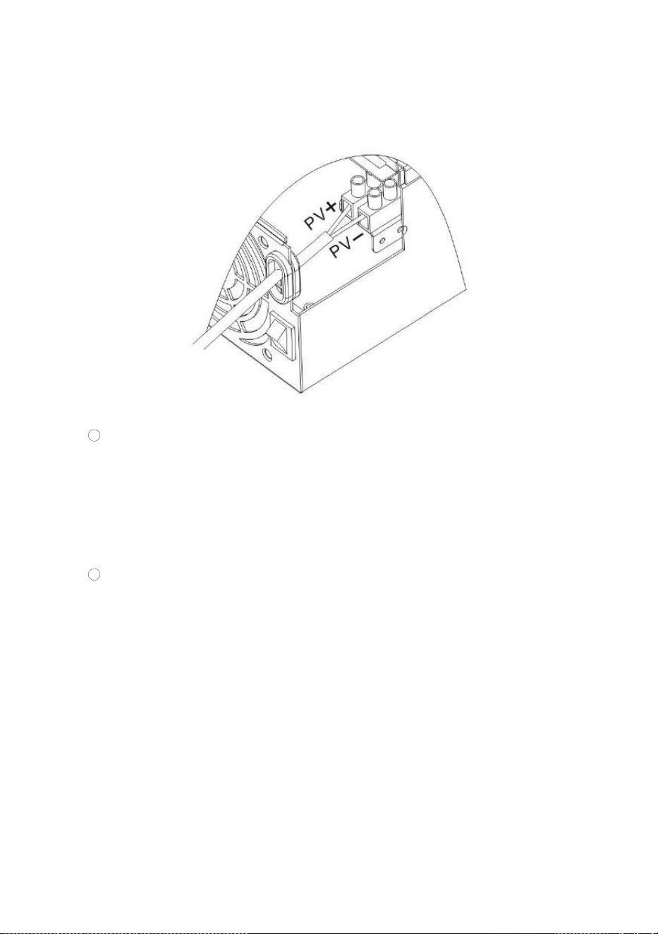
All-in-one solar charge inverter V4.1
1 3
position shown in the figure below.
PV+: PV input positive pole PV-: PV input negative pole
BAT wiring method:
1
Prior to wiring, disconnect the external circuit breaker and confirm that the wire used is
thick enough. Please refer to Section 2.2 “ Wiring Specifications and Circuit Breaker
Selection”. The BAT wire needs to be connected to the machine through the O-type
terminal. The O-type terminal with an inner diameter of 6 mm is recommended. The O-
type terminal shall firmly press the BAT wire to prevent excessive heat generation
caused by excessive contact resistance;
2
Properly connect the BAT wire according to the wire sequence and terminal position
shown in the figure below.
BAT+: Battery positive electrode BAT-: Battery negative electrode

All-in-one solar charge inverter V4.1
1 4
Warnings:
1 Mains input, AC output and PV array will generate high voltage. So, before wiring, be sure to
disconnect the circuit breaker or fuse;
2 Be very careful during wiring; do not close the circuit breaker or fuse during wiring, and ensure that
the “+” and “-” pole leads of each component are connected properly; a circuit breaker must be
installed at the battery terminal. Refer to Section 2.2 “ Wiring Specifications and Circuit Breaker
Selection” to select a right circuit breaker. Before wiring, be sure to disconnect the circuit breaker to
prevent strong electric sparks and avoid battery short circuit; if the all-in-one solar charge inverter is
used in an area with frequent lightning, it is recommended to install an external lightening arrester at
the PV input terminal.
Step 4: Check if the wiring is correct and firm. In particular, check if the battery polarity is reversed, if the
PV input polarity is reversed and if the AC input is properly connected.
Step 5: Install the terminals cover.
All-in-one solar charge inverter V4.1
1 5
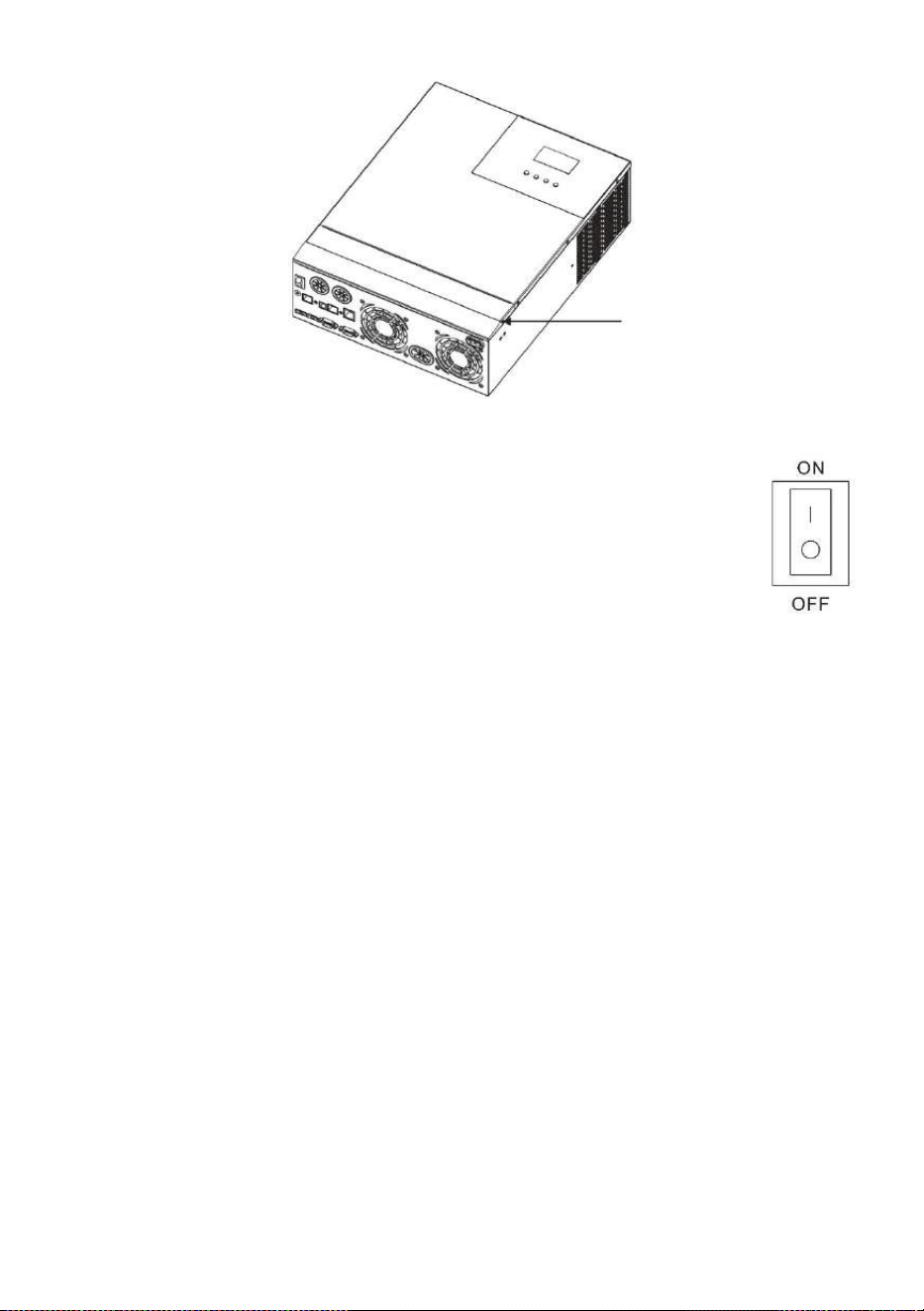
Step 6: Turn on the all-in-one solar charge inverter
First, close the circuit breaker at the battery terminal, and then turn the rocker switch
on the left side of the machine to the "ON" state. The "AC/INV" indicator flashing
indicates that the inverter is working normally. Close the circuit breakers of the PV
array and the Mains. Finally, turn on AC loads one by one as the AC output is normal
to avoid a protection action caused by a large momentary shock due to simultaneous
turning on the loads simultaneously. Now, the machine goes into a normal
operation according to the set mode.
Note: If power is supplied to different AC loads, it is recommended to first turn on the load with a large
surge current. After the load is stable, turn on the load with a small surge current.
Note: If the all-in-one solar charge inverter does not work properly or the LCD or indicator is abnormal,
refer to Chapter 6 to handle the exceptions.
2.4 Installation and wiring
2.4.1 Introduction
1. Maximum six all-in-one solar charger inverters can be used for parallel operation.
2. When using the parallel operation function, the following connecting lines (package accessories)
shall be firmly and reliably connected:
Parallel communication line*1: Current sharing detection line*1:

All-in-one solar charge inverter V4.1
1 6
2.4.2 Precautions for connecting the parallel connecting lines
Warning:
1, Battery wiring:
Parallel connection in single or spilit phase: Ensure that all all-in-one solar charger inverters are
connected to the same battery, with BAT + connected to BAT + , BAT - connected to BAT -, and
that the connection is correct with the same wiring length and line diameter before power on and
start-up, so as to avoid the abnormal operation of parallel system output caused by wrong
connection.
2, AC OUT wiring:
Parallel connection in single phase: Ensure L-to-L, N-to-N and PE-to-PE connection for all all-in-
one solar charger inverters, and that the connection is correct with the same wiring length and
line diameter before power on and start-up, so as to avoid the abnormal operation of parallel
system output caused by wrong connection. For specific wiring, please refer to 2.4.3 Wiring
Diagram
Parallel connection in spilit phase: Ensure N-to-N and PE-to-PE connection for all all-in-one
solar charger inverters. The L lines of all inverters connected to the same phase need to be
connected together. But L lines of different phases cannot be joined together. Other connection
precautions are the same as parallel connection in single phase. For specific wiring, please refer to
2.4.4Wiring Diagram
3 AC IN wiring:
Parallel connection in single phase: Ensure L-to-L, N-to-N and PE-to-PE connection for all all-in-
one solar charger inverters, and that the connection is correct with the same wiring length and
line diameter before power on and start-up, so as to avoid the abnormal operation of parallel
system output caused by wrong connection. Meanwhile, it is not allowed to have multiple
different AC source inputs to avoid damage to the external equipment of the inverter. The

All-in-one solar charge inverter V4.1
1 7
consistency and uniqueness of AC source input shall be ensured. For specific wiring, please refer
to 2.4.3 Wiring Diagram.
Parallel connection in spilit phase: Ensure N-to-N and PE-to-PE connection for all all-in-one
solar charger inverters. The L lines of all inverters connected to the same phase need to be
connected together. But L lines of different phases cannot be joined together. Other connection
precautions are the same as parallel connection in single phase. For specific wiring, please refer to
2.4.4 Wiring Diagram.
4, Wiring of parallel communication line:
Parallel connection in single or spilit phase: Our company's parallel communication line is a
DB15 standard computer cable with shielding function. Ensure the "one-in-one-out" rule when
connecting each inverter, that is, connect the male connector (out) of this inverter with the female
connector (in) of the inverter to be paralleled. Do not connect the male connector of the inverter
to its female connector. In addition, make sure to tighten the parallel communication line of each
inverter with self-contained end screws of DB15 to avoid the abnormal operation or damage of
the system output caused by the falling off or poor contact of the parallel communication line.
5, Wiring of current sharing detection line:
Parallel connection in single phase: Our company's current sharing detection line is a twisted
connection line. Ensure the "one-in-one-out" rule when connecting each inverter, that is, connect
the current sharing line of the inverter with the current sharing green port of the inverter to be
paralleled (choose one port from the two, and there is no mandatory sequence requirement). The
current sharing ports of the inverter cannot be connected to each other. In addition, make sure
that the red and black current sharing connection lines of each inverter are not manually
exchanged, and make sure to tighten the lines with self-contained screws to avoid the abnormal
operation or damage of the system output caused by abnormal parallel current sharing detection.
For specific wiring, please refer to 2.4.3 Wiring Diagram.
Parallel connection in spilit phase: The current sharing detection lines of all inverters connected
to the same phase need to be connected together. But the current sharing detection lines of
different phases cannot be joined together. Other connection precautions are the same as parallel
connection in single phase. For specific wiring, please refer to 2.4.4 Wiring Diagram.
6,
Before or after connecting the system, please carefully refer to the following system wiring
All-in-one solar charge inverter V4.1
1 8
diagram to ensure that all wiring is correct and reliable before power on.
7,
fter the system is wired, powered on and in normal operation, if a new inverter needs to be
connected, make sure to disconnect the battery input, PV input, AC input and AC output, and that
all all-in-one solar charger inverters are powered off before reconnecting into the system.
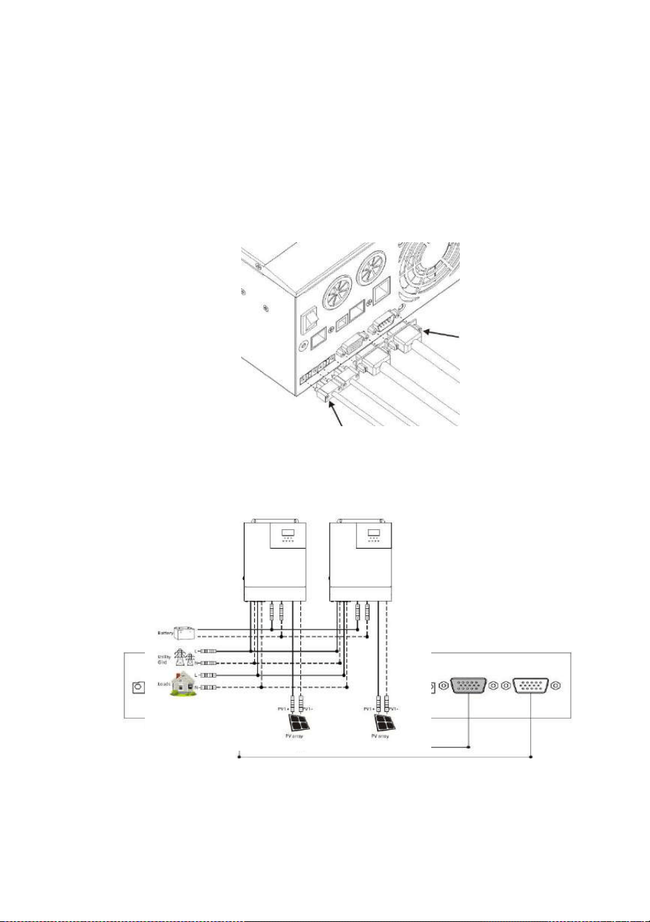
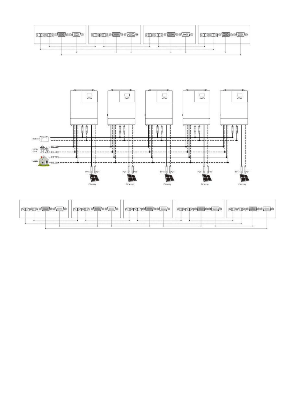
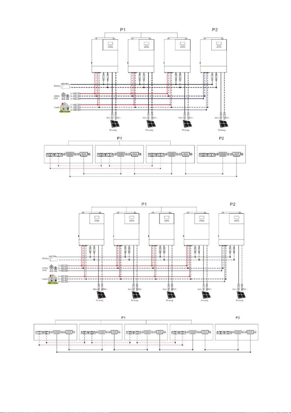
2.4.3 Schematic diagram of parallel connection in single phase
1. The parallel communication line and current sharing detection line of the all-in-one solar charger
inverter need to be locked with screws after connecting. The schematic diagram is as follows:
2. In case of parallel operation with multiple inverters, the schematic diagram of parallel connection
is as follows( for U and S series model):
a) Two all-in-one solar charger inverters of the system connected in parallel:
b
) Three all-in-one solar charger inverters of the system connected in parallel:
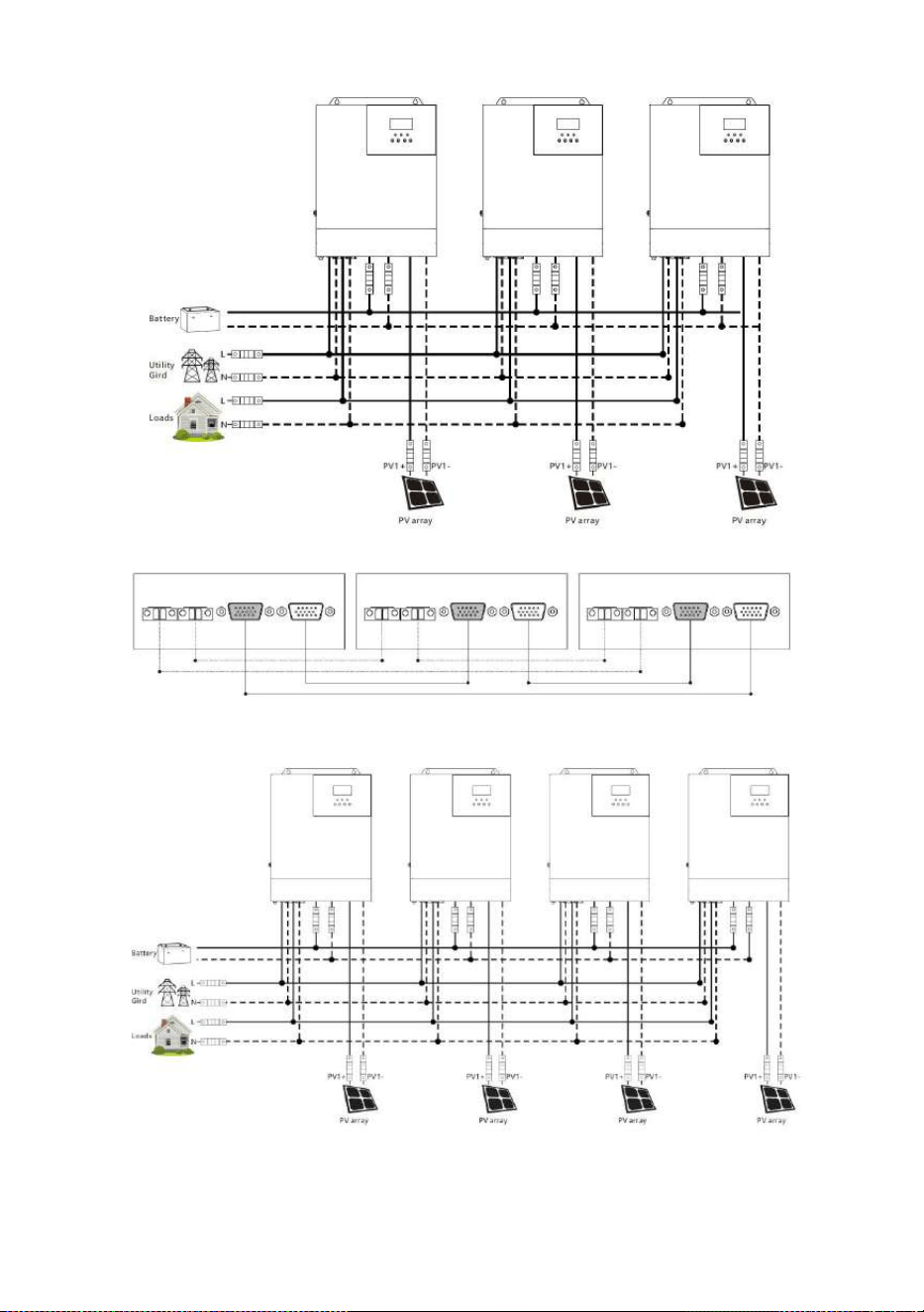
All-in-one solar charge inverter V4.1
1 9
c) Four all-in-one solar charger inverters of the system connected in parallel:
All-in-one solar charge inverter V4.1
20
d) Five all-in-one solar charger inverters of the system connected in parallel:
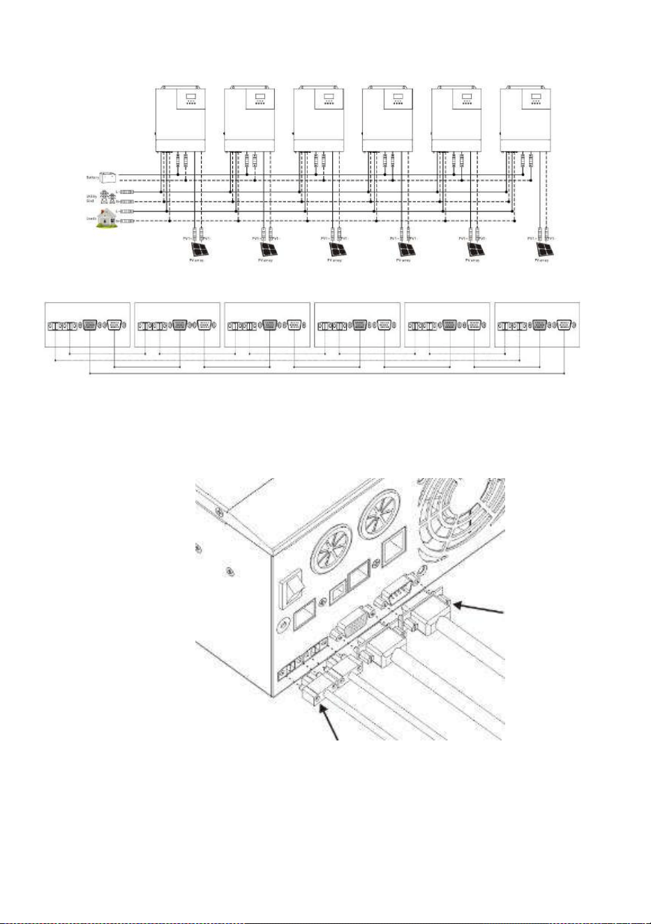
e) Six all-in-one solar charger inverters of the system connected in parallel:
All-in-one solar charge inverter V4.1
21
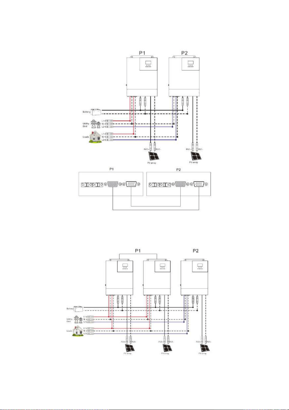
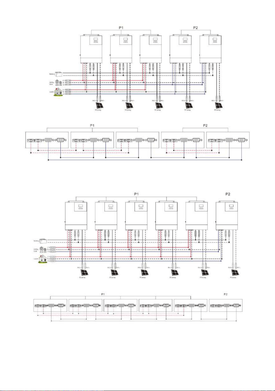
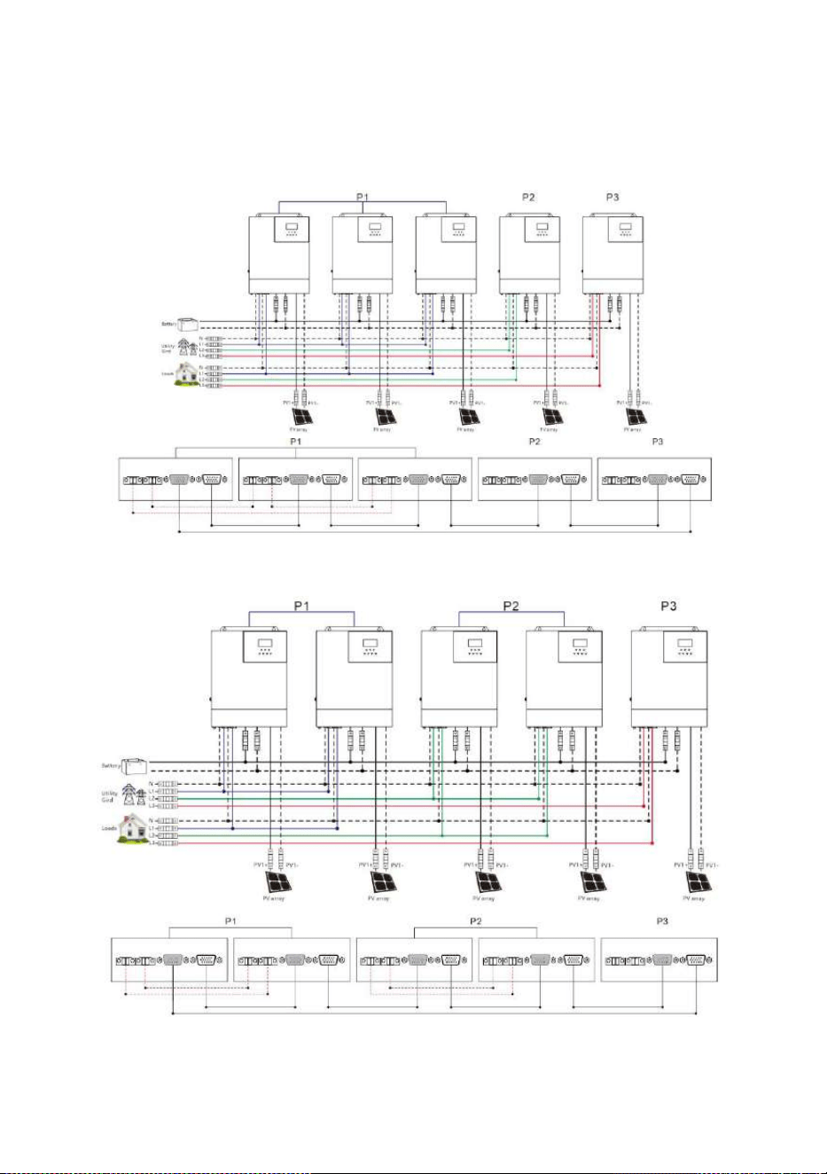
2.4.4 Schematic diagram of parallel connection in spilit phase
1. The parallel communication line and current sharing detection line of the all-in-one solar charger
inverter need to be locked with screws after connecting. The schematic diagram is as follows:
2. In case of parallel operation with multiple inverters, the schematic diagram of parallel connection
is as follows:
Parallel Operation in two phase (only for U series model can be set):
All-in-one solar charge inverter V4.1
22
a
)
Two all-in-one solar charger inverters of the system connected in two phase:
1+1 system:
b
)
Three all-in-one solar charger inverters of the system connected in two
phase:
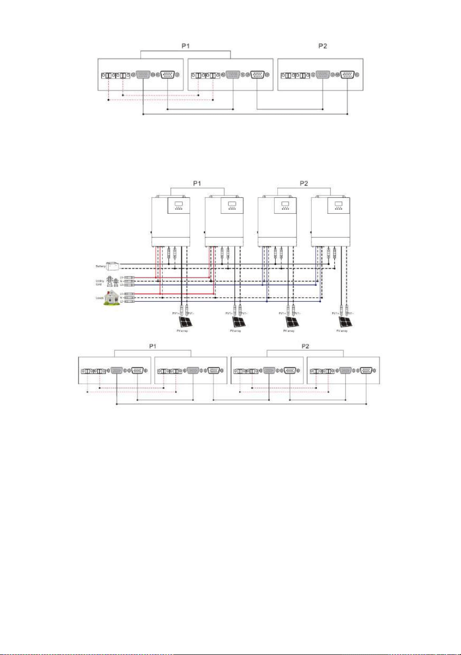
2+1 system:
All-in-one solar charge inverter V4.1
23
c) Four all-in-one solar charger inverters of the system connected in two phase:
2+2 system:
3+1 system:
All-in-one solar charge inverter V4.1
24
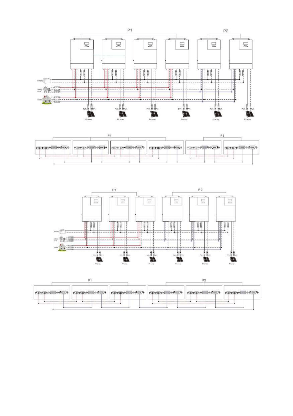
d
)
Five all-in-one solar charger inverters of the system connected in two phase:
4+1 system:
3+2 system:
All-in-one solar charge inverter V4.1
25
e
)
Six all-in-one solar charger inverters of the system connected in two phase:
5+1 system:
4+2 system:
All-in-one solar charge inverter V4.1
26
3+3 system:
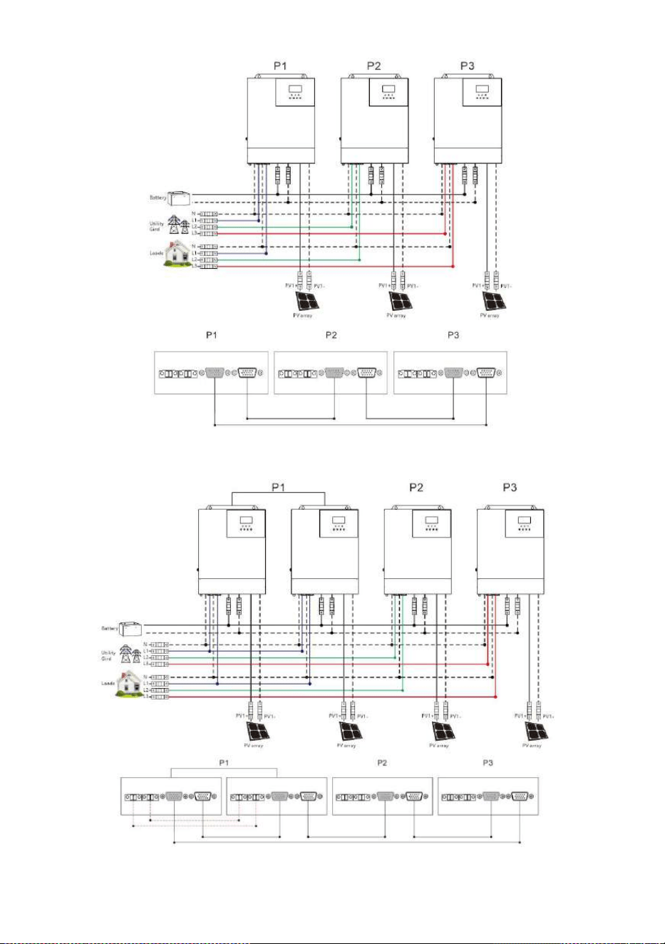
Parallel Operation in three phase (for U and S series model):
a
)
Three all-in-one solar charger inverters of the system connected in three phase:
1+1+1 system:
All-in-one solar charge inverter V4.1
27
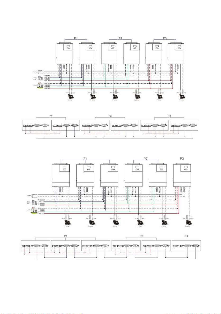
b) Four all-in-one solar charger inverters of the system connected in three phase:
2+1+1 system:
All-in-one solar charge inverter V4.1
28
c) Five all-in-one solar charger inverters of the system connected in three phase:
3+1+1 system:
2+2+1 system:
All-in-one solar charge inverter V4.1
29
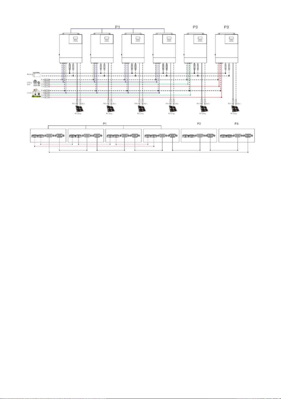
d) Six all-in-one solar charger inverters of the system connected in three phase:
2+2+2 system:
3+2+1 system:
4+1+1 system:
All-in-one solar charge inverter V4.1
30
Note:
1) Before starting up and running, please check whether the connection was correct to avoid any
abnormalities in the system.
2) All wiring must be fixed and reliable to avoid wire drop during use.
3) When the AC output is wired to the load, it shall be properly wired according to the requirements
of the electrical load equipment to avoid damage to the load equipment.
4) Settings [38] need to be set consistently or only for the host. When the machine is running, the
voltage set by the host shall prevail, and the master will force the rewrite of the other slave
machines to keep the same set. Only can be set in the standby mode.
5) When using parallel or spilit phase separation function, the [31] setting items need to be
set accordingly.
Parallel Operation in two phase:
When the parameter [38] setting item=120 for U series model. The [31] setting item:
All connected P1-phase inverters are set to "2P0":
If all connected P2-phase inverters are set to "2P1", the AC output line voltage difference is
120 degrees (L1-L2), line voltage is 120*1.732= 208Vac; Phase voltage is 120Vac (L1-N; L2-N).
If all connected P2-phase inverters are set to "2P2", the AC output line voltage difference is
180 degrees (L1-L2), line voltage is 120*2= 240Vac; Phase voltage is 120Vac (L1-N; L2-N).
All-in-one solar charge inverter V4.1
31
Parallel Operation in three phase:
The [31] setting item:
All connected P1-phase inverters are set to "3P1";
All connected P2-phase inverters are set to "3P2";
All connected P3-phase inverters are set to "3P3";
U series model: When the parameter [38] setting item=120 for U series model. The AC
output line voltage difference is 120 degrees, each line voltage (L1-L2/L1-L3/L2-L3) is
120*1.732= 208Vac; Each phase voltage is 120Vac (L1-N; L2-N; L3-N).
S series model: When the parameter [38] setting item=230 for S series model. The AC
output line voltage difference is 120 degrees, each line voltage (L1-L2/L1-L3/L2-L3) is
230*1.732= 398Vac; Each phase voltage is 230Vac (L1-N; L2-N; L3-N).
6) When the phase sequence is set [31] on the screen, the setting one is turned on to set, and the
other machines are turned off. One by one set. Finally, power off and start up again.
7) After the system runs, the output voltage is measured correctly, and then the load setting is
connected.
3. Operating modes
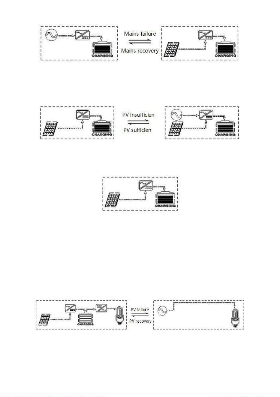
3.1 Charging mode
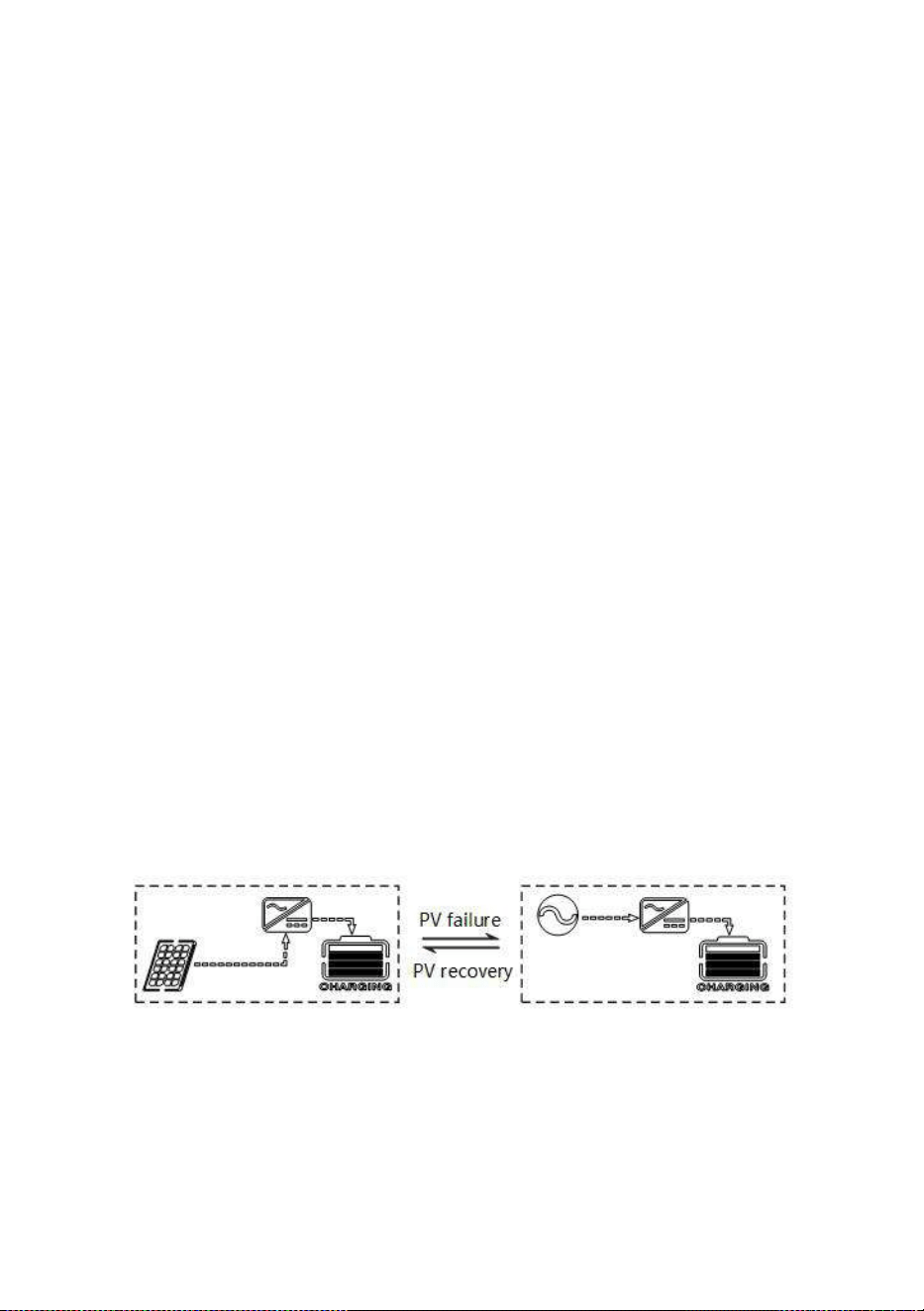
1) PV priority: PV module will charge the battery preferentially, and the battery is charged by the Mains
only when the PV system fails. During the day, solar energy is fully used to charge, while at night, it
converts to the Mains. This can maintain battery level, and is ideal for areas where the grid is relatively
stable and electricity price is relatively high.
2) Mains priority: The Mains supply is preferentially used to charge the battery. Only when the Mains
fails, the PV charging can be activated.
All-in-one solar charge inverter V4.1
32
3) Hybrid charging: PV and mains hybrid charging. PV MPPT charging is a priority, and when PV energy
is insufficient, the mains supply supplements. When the PV energy is sufficient again, the mains stops
charging. This is the fastest charging mode, suitable for the areas where power grid is unstable,
providing sufficient backup power supply at any time.
4) Only Solar (Only Solar): Only PV charging, without Mains charging. This is the most energy-efficient
way in which battery is charged only by solar panels, and is usually used in areas with good lighting
conditions.
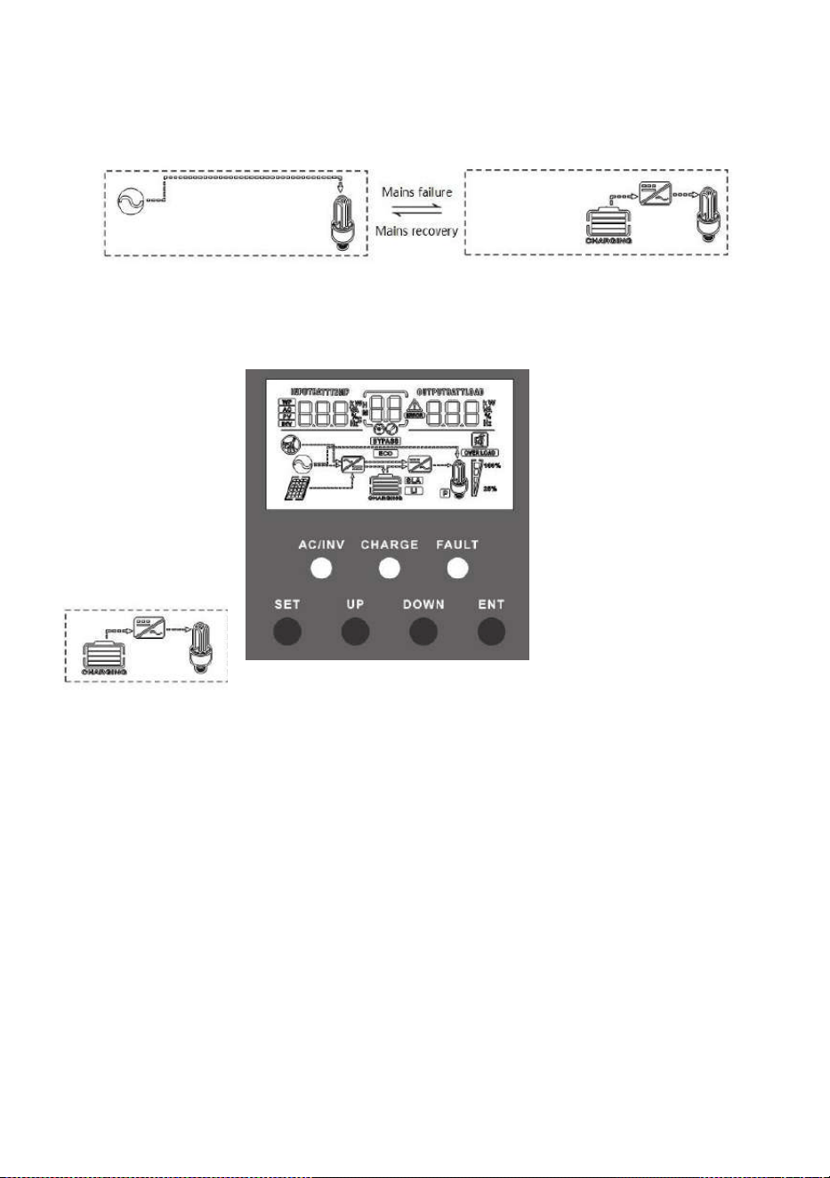
3.2 Output mode
1. PV priority mode:
Switch to mains supply when the PV charging fails. This mode maximizes the use of solar energy
while maintaining battery power, suitable for use in the areas with relatively stable grid. Power
supply priority:Solar—》Utility—》Battery.
2. Mains priority mode:
Switch to inverter only when the mains fails (when there was mains power, switch to mains power for
All-in-one solar charge inverter V4.1
33
charging and power supply).Then, the unit is equivalent to a backup UPS, suitable for areas with
unstable grid. Switching does not affect PV charging. Power supply priority:Utility—》Solar—》
Battery.
3. Battery priority mode:
Switch to mains supply only when the battery discharge undervoltage is lower than the set point
(item 04). When
the charging battery is higher
than the set point
of (05 setting item), switch to the
battery discharge
mode. This can cycle the battery
charge and
discharge. This mode maximizes
the use of DC
power and is used in the area
with stable grid.
Switching does not affect PV
charging. Power
supply priority : Solar— 》
Battery—》Utility.
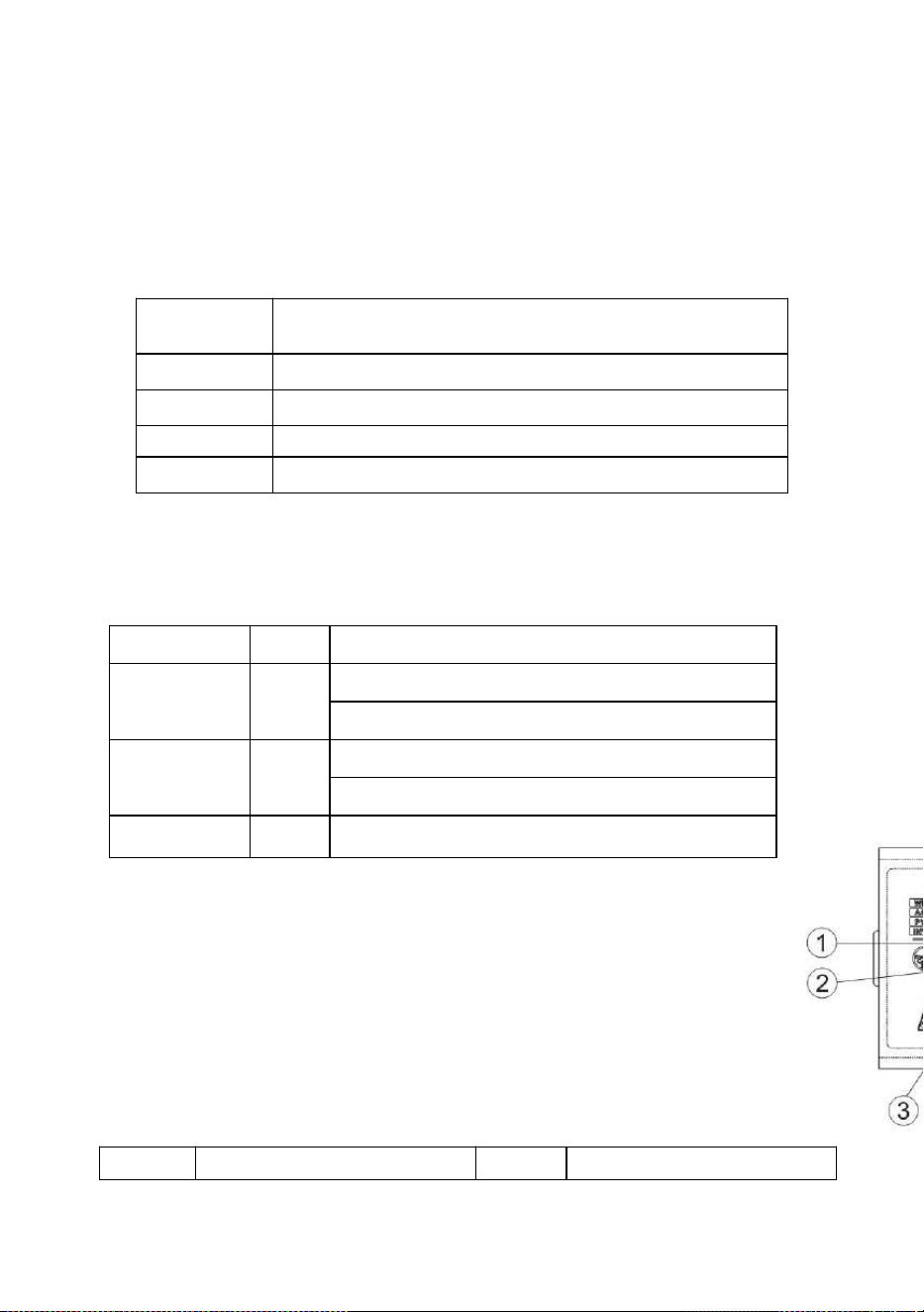
4. LCD screen operating instructions
4.1 Operation and display panel
The operation and display panel is as shown below, including 1 LCD screen, 3 indicators and 4 operation
buttons.
All-in-one solar charge inverter V4.1
34
Operation buttons introduction
Indicators introduction
LCD
screen
introdu
ction
Function
buttons
Description
SET
Enter/Exit Settings menu
UP
Previous choice
DOWN
Next choice
ENT
Confirm/Enter Options under the settings menu,
Indicators
Colors
Description
AC/INV
Yellow
Steady on: Mains output
Flash: Inverter output
CHARGE
Green
Flash: Fast charging
Steady on: Floating charge
FAULT
Red
Flash : Fault state
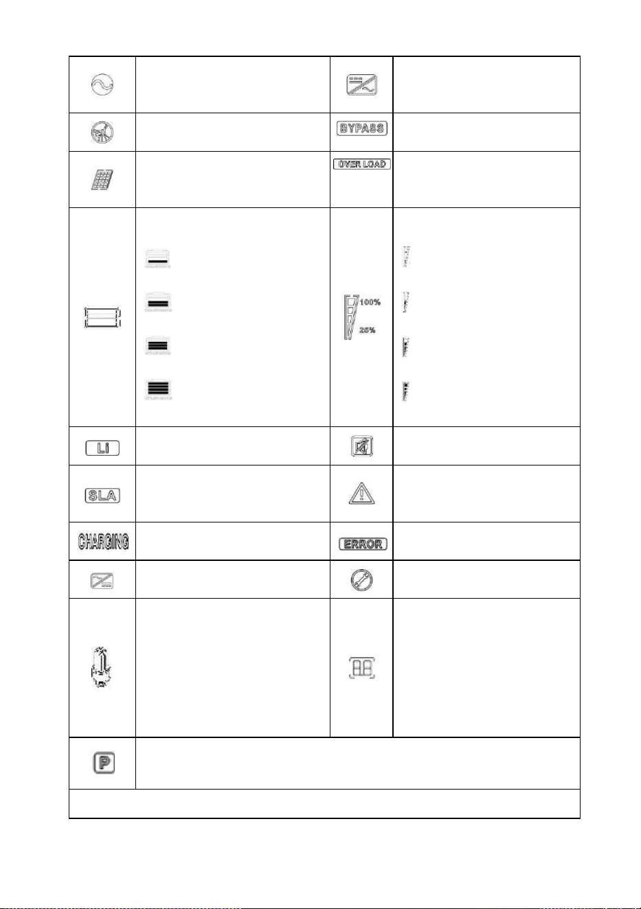
Icons
Functions
Icons
Functions
All-in-one solar charge inverter V4.1
35
Indicates that the AC input
terminal has been connected to
the grid
Indicates that the inverter circuit
is working
Indicates that the AC input mode
in APL mode (wide voltage range)
Indicates that the machine is in
the Mains Bypass mode
Indicates that the PV input
terminal has been connected to
the solar panel
Indicates that the AC output is in
an overload state
Indicates that the machine has
been connected to the battery:
indicates that the remaining
battery is 0%~24%;
indicates that the remaining
battery is 25%~49%;
indicates that the remaining
battery is 50%~74%;
indicates that the remaining
battery is 75%~100%.
Indicates the percentage of AC
output loads:
indicates that the load
percentage is 0%~24%;
indicates that the load
percentage is 25%~49%,
indicates that the load
percentage is 50%~74%,
indicates that the load
percentage is ≥75%
Indicates that the battery type of
the machine is a lithium battery
Indicates that the buzzer is not
enabled
Indicates that the current battery
type of the machine is a lead-acid
battery
Indicates that the machine has
an alarm
Indicates that the battery is in
charging state
Indicates that the machine is in a
fault condition
Indicates that the AC/PV charging
circuit is working
Indicates that the machine is in
setup mode
Indicates that the AC output
terminal has an AC voltage output
The parameters displayed in the
middle of the screen:
1. In the non-setup mode, the
alarm or fault code is displayed.
2. In the setup mode, the
currently set parameter item
code is displayed.
In parallel operation, this icon indicates that this inverter is the host, which is only
valid in parallel mode.
Parameters display on the left side of the screen: input parameters
All-in-one solar charge inverter V4.1
36
Real-time data viewing method
On the LCD main screen, press the “UP” and “DOWN” buttons to scroll through the real-time data of
the machine.
Page
Parameters on the left side of the
screen
Parameters
in the middle
of the screen
Parameters on the right side of
the screen
1
INPUT BATT V
(Battery input voltage)
Fault code
OUTPUT LOAD V (Output
load voltage)
2
BMS BATT V
(BMS battery voltage,This
parameter is valid when BMS is
enabled
)
BMS BATT SOC
(
BMS Percentage of remaining
BMS battery capacity This
parameter is valid when BMS is
enabled)
3
PV TEMP ℃
PV OUTPUT KW
Indicates AC input
Indicates PV input
Indicates inverter circuit
This icon is not displayed
Display battery voltage, battery charge total current, mains charge power, AC input
voltage, AC input frequency, PV input voltage, internal heat sink temperature,
software version
Parameters display on the right side of the screen: Output parameters
Indicates output voltage, output current, output active power, output apparent
power, battery discharge current, software version; in setup mode, displays the set
parameters under the currently set parameter item code
Arrow display
①
The arrow is not displayed
⑤
Indicates the charging circuit
charging the battery terminal
②
Indicates the grid supplying power
to the load
⑥
The arrow is not displayed
③
Indicates grid supplying power to
the charging circuit
⑦
Indicates the battery terminal
supplying power to the inverter
circuit
④
Indicates PV module supplying
power to the charging circuit
⑧
Indicates the inverter circuit
supplying power to the load
All-in-one solar charge inverter V4.1
37
(PV charger heatsink temperature)
(PV output power)
4
PV INPUT V
(PV input voltage)
PV OUTPUT A
(PV output current)
5
INPUT BATT A
(Input battery current)
OUTPUT BATT A
(Battery output current)
6
INPUT BATT KW
(Battery input power)
OUTPUT BATT KW
(Battery output power)
7
AC INPUT Hz
(AC input frequency)
AC OUTPUT LOAD Hz
(AC output frequency)
8
AC INPUT V
(AC input voltage)
AC OUTPUT LOAD A
(AC output load current)
9
INPUT V
(For maintain)
OUTPUT LOAD KVA
(
Load apparent power
)
10
INV TEMP ℃
(AC charge or battery discharge
heatsink temperature)
INV OUTPUT LOAD KW
(Load active power)
11
APP software version
Bootloader software version
12
Model Battery Voltage Rating
Model Output Power Rating
13
Model PV Voltage Rating
Model PV Current Rating
14
RS485 Address Number
Phase Sequence Number
4.2 Setup parameters description
Buttons operation instructions: Press the “ SET” button to enter the setup menu and exit the setup
menu. After entering the setup menu, the parameter number [00] will flash. At this point, press the “UP”
and “DOWN” buttons to select the code of parameter item to be set. Then, press the “ENT” button to
enter the parameter editing mode, and the value of the parameter is flashing. Adjust the value of the
parameter with the “ UP” and “ DOWN ” buttons. Finally, press the “ENT” button to complete the
parameter editing and return to the parameter selection state.
Note:
in parallel mode, all machines will synchronize the setting parameters of the host (the machine
with "P" is displayed on the display screen) before startup. After startup, the setting parameters of any
machine will be synchronized to other machines in the system

All-in-one solar charge inverter V4.1
38
Parameter
no.
Parameter
name
Settings
Description
00
Exit setting
menu
[00] ESC
Exit the setup menu
01
Output
source priority
[01] SOL
PV priority mode, switching to the Mains when
the PV fails or the battery is lower than the set
value of parameter [04].
[01] UTI default
Mains priority mode, switching to inverter only
when the mains fails.
[01] SBU
Battery priority mode. Switch to mains power
only when the battery is under voltage or lower
than the setting value of parameter [04]; Switch
to battery discharge only when the battery is
fully charged or higher than the setting value of
parameter [05].
02
Output
Frequency
[02] 50.0
Bypass self-adaptation; when the mains is
connected, it automatically adapts to the mains
frequency; when the mains is disconnected, the
output frequency can be set through this menu.
The default output frequency of the 230V
machine is 50HZ, and the 120V machine 60HZ.
[02] 60.0
03
AC Input
Voltage Range
[03] APL
Wide mains input voltage range of 230V
machine: 90~280V
Mains input voltage range of 120V machine:
90~140V
[03] UPS default
Narrow mains input voltage range of 230V
machine: 170~280V
Mains input voltage range of 120V machine:
90~140V
04
Battery Power
to Utility
Setpoint
[04] 43.6V
default
When the parameter [01] =SBU/SOL, the battery
voltage is lower than the set value, and the
output is switched from the inverter to the mains.
Setting range: 40V~52V. Cannot exceed the
value of [14] settings. (Invalid after normal BMS
communication)
05
Utility to
Battery Power
Setpoint
[05]57.6V default
When the parameter [01] =SBU/SOL, the battery
voltage is higher than the set value, and the
output is switched from the mains to the inverter.
Setting range: 48V~60V. Cannot be lower than
the value of [04] / [35] settings. (Invalid after

All-in-one solar charge inverter V4.1
39
Parameter
no.
Parameter
name
Settings
Description
normal BMS communication)
06
Charger source
priority
[06] CSO
PV priority charging; only when the PV charging
fails, the mains charging is started.
[06] CUB
Mains priority charging; only when the mains
charging fails, the PV charging is started.
[06] SNU default
PV and Mains hybrid charging; PV charging is a
priority, and when the PV energy is insufficient,
the Mains charging supplements. When the PV
energy is sufficient, the Mains charging stops.
Note: Only when the Mains bypass output is
loaded, the PV charging and the mains charging
can work at the same time. When the inverter
works, only the PV charging can be started.
[06] OSO
Only PV charging, with the Mains charging not
activated.
07
Max charger
current
[07] 80A default
Max charger current (AC charger+PV charger).
S series model:setting range 0~140A;
U series model:setting range 0~120A;
08
Battery Type
[08] USE
User-defined; all battery parameters can be set.
[08] SLd
Sealed lead-acid battery; constant-voltage
charge voltage: 57.6V, floating charge voltage:
55.2V.
[08] FLd
Vented lead-acid battery; constant-voltage
charge voltage: 58.4V, floating charge voltage:
55.2V.
[08] GEL default
Colloidal lead-acid battery; constant-voltage
charge voltage: 56.8V, floating charge voltage:
55.2V.
[08]
LF14/LF15/LF16
Lithium iron phosphate battery LF14/LF15/LF16,
corresponding to 14strings ,15 strings and 16
strings of lithium iron phosphate battery; for 16
strings, default constant-voltage charge voltage
is 56.8V; for 15 strings, default constant-voltage
charge voltage is 53.2V; for 14 strings, default
constant-voltage charge voltage is 49.2V; allow
adjustable.

All-in-one solar charge inverter V4.1
40
Parameter
no.
Parameter
name
Settings
Description
[08] N13/N14
Ternary lithium battery; which is adjustable.
09
Battery boost
charge voltage
[09] 56.8V
default
Boost charge voltage setting; the setting range is
48V~58.4V, with step of 0.4V; it is valid for user-
defined battery and lithium battery.
10
Battery boost
charge time
[10] 120 default
Boost charge maximum time setting, which
means the maximum charging time to reach the
set voltage of parameter [09] during constant-
voltage charging. The setting range is
5min~900min, with a step of 5 minutes. It is valid
for user-defined battery and lithium battery.
11
Battery floating
charge voltage
[11] 55.2V
default
Floating charge voltage, setting range:
48V~58.4V, step: 0.4V, valid when battery type is
user-defined.
12
Battery over
discharge
voltage (delay
off)
[12] 42V default
Over-discharge voltage; when the battery voltage
is lower than this judgment point, delay the time
set by parameter [13] and turn off inverter
output. Setting range is 40V~48V, with a step of
0.4V. It is valid for user-defined battery and
lithium battery.
13
Battery over
discharge delay
time
[13] 5S default
Over-discharge delay time; when the battery
voltage is lower than the parameter [12], the
inverter output will be turned off after the time
set by this parameter is delayed. The setting
range is 5S~55S, with a step of 5S. It is valid for
user-defined battery and lithium battery.
14
Battery under
voltage alarm
[14] 44V default
Battery undervoltage alarm point; when the
battery voltage is lower than the point, an
undervoltage alarm is given, and the output is
not turned off; the setting range is 40V~52V,
with a step of 0.4V. It is valid for user-defined
battery and lithium battery.
15
Battery
discharge limit
voltage
[15] 40V default
Battery discharge limit voltage; when the battery
voltage is lower than the point, the output is
turned off immediately; the setting range is
40V~52V, with a step of 0.4V. It is valid for user-
defined battery and lithium battery.
16
Battery
[16] DIS
Equalizing charge is disabled

All-in-one solar charge inverter V4.1
41
Parameter
no.
Parameter
name
Settings
Description
equalization
enable
[16] ENA default
Equalizing charge is enabled, only valid for
vented lead-acid battery and sealed lead-acid
battery
17
Battery
equalization
voltage
[17] 58.4V
default
Equalizing charge voltage; setting range:
48V~58.4V, with a step of 0.4V; valid for vented
lead-acid battery and sealed lead-acid battery
18
Battery
equalized time
[18] 120 default
Equalizing charge time; setting range:
5min~900min, with a step of 5 minutes; valid for
vented lead-acid battery and sealed lead-acid
battery
19
Battery
equalized time
out
[19] 120 default
Equalizing charge delay; setting range:
5min~900min, with a step of 5 minutes; valid for
vented lead-acid battery and sealed lead-acid
battery
20
Battery
equalization
interval
[20] 30 default
Equalizing charge derating time, 0~30days, with
a step of 1 day; valid for vented lead-acid battery
and sealed lead-acid battery
21
Battery
equalization
immediately
[21] DIS default
Stop equalizing charge immediately.
[21] ENA
Start equalizing charge immediately.
22
Power saving
mode
[22] DIS default
Power saving mode disabled.
[22] ENA
After the power saving mode is enabled, if the
load is null or less than 50W, the inverter output
is turned off after a delay for a certain period of
time. When the load is more than 50W, the
inverter automatic restart.
23
Restart when
over load
[23] DIS
Automatic restart when overload is disabled. If an
overload occurs and the output is turned off, the
machine will not restart.
[23] ENA default
Automatic restart when overload is enabled. If an
overload occurs and the output is turned off, the
machine will restart after a delay of 3 minutes.
After it reaches 5 cumulative times, the machine
will not restart.
24
Restart when
over
temperature
[24] DIS
Automatic restart when over temperature is
disabled. If an over-temperature shutdown
occurs, machine will not restart to turn the

All-in-one solar charge inverter V4.1
42
Parameter
no.
Parameter
name
Settings
Description
output on.
[24] ENA default
Automatic restart when over temperature is
enabled. If an over-temperature shutdown
occurs, the machine will restart when the
temperature drops.
25
Alarm enable
[25] DIS
Alarm is disabled
[25] ENA default
Alarm is enabled
26
Beeps while
primary source
is interrupted
[26] DIS
Alarm beep is disabled when the status of the
main input source changes
[26] ENA default
Alarm beep is enabled when the status of the
main input source changes
27
Bypass output
when over load
[27] DIS
It is disabled to automatically switch to the Mains
when the inverter is overloaded.
[27] ENA default
It is enabled to automatically switch to the Mains
when the inverter is overloaded.
28
Max AC charger
current
[28]60A default
S series model:Max AC charger current. Setting
range: 0~60A;60A default.
[28]40A default
U series model:Max AC charger current. Setting
range: 0~40A;40A default.
29
Split Phase
[29] DIS default
Supply for industrial frequency transformer
(disabled)
[29] ENA
Supply for industrial frequency transformer
(enabled)
30
Model ID
setting
[30] 1 default
RS485 address number. Parallel mode needs to
be set in the range of 1-6. When the power is
first turned on, it will be automatically distributed
31
AC output
mode (can be
set in the
standby mode
only)
[31] SIG
When single inverter is used, the default is SIG
mode. For S and U series model can be set.
[31] PAL default
In parallel operation with single phase, for S and
U series model can be set. Please refer to 2.4
Wiring Diagram.
[31] 2P0/2P1/2P2
In split phase operation with two phase, only for
U series model can be set. At least one inverter
is required for each phase. Please refer to 2.4
Wiring Diagram.
When the parameter [38] setting item=120 for U series model.
All connected P1-phase inverters are set to "2P0":

All-in-one solar charge inverter V4.1
43
Parameter
no.
Parameter
name
Settings
Description
1) If all connected P2-phase inverters are set to "2P1", AC output line
voltage difference is 120 degrees (L1-L2), line voltage is 120*1.732=
208Vac; Phase voltage is 120Vac (L1-N; L2-N).
2) If all connected P2-phase inverters are set to "2P2", AC output line
voltage difference is 180 degrees (L1-L2), line voltage is 120*2=
240Vac; Phase voltage is 120Vac (L1-N; L2-N).
[31] 3P1/3P2/3P3
In split phase operation with three phase, for S
and U series model can be set. At least one
inverter is required for each phase. Please refer
to 2.4 Wiring Diagram.
When the parameter [38] setting item=120 for U series model.
All connected P1-phase inverters are set to "3P1";
All connected P2-phase inverters are set to "3P2";
All connected P3-phase inverters are set to "3P3";
AC output line voltage difference is 120 degrees (L1-L2/L1-L3/L2-L3),
each line voltage is 120*1.732= 208Vac; Each phase voltage is 120Vac
(L1-N; L2-N; L3-N).
When the parameter [38] setting item=230 for S series model.
All connected P1-phase inverters are set to "3P1";
All connected P2-phase inverters are set to "3P2";
All connected P3-phase inverters are set to "3P3";
AC output line voltage difference is 120 degrees (L1-L2/L1-L3/L2-L3),
each line voltage is 230*1.732= 398Vac; Each phase voltage is 230Vac
(L1-N; L2-N; L3-N).
32
RS485-2
Communication
function
[32]SLA default
RS485-2 port for PC or telecommunication
control
[32] BMS
RS485-2 port for BMS communication.
33
BMS
communication
protocol
When the parameter [32] setting item =BMS, you can choose to
match the battery manufacturer's BMS protocol to communicate with
BMS for the lithium battery protection.
[35] WOW
default
PAC=PACE,RDA=Ritar,AOG=ALLGRAND
BATTERY,OLT=OLITER,HWD=SUNWODA,
DAQ=DAKING,WOW=SRNE, PYL=PYLONTECH,
SHO=FOXess,XXL=XYE,POL=Powmr,
VOL=Weeland

All-in-one solar charge inverter V4.1
44
Parameter
no.
Parameter
name
Settings
Description
35
Battery
undervoltage
recovery point
[35] 52V default
When the battery voltage is under voltage, the
battery voltage needs to recover more than this
set value before the inverter starts the output
36
Max PV charger
current
[36] 80A default
Max PV charger current. Setting range: 0~80A
37
Battery fully
charged
recovery point
[37] 52V default
After the battery is fully charged, it needs to be
lower than this set voltage before it can be
recharged
38
AC output
voltage setting
(only can be set
in the standby
mode )
[38] default
U series model:120V default.
Allow to set to 100Vac/105Vac/110Vac/120Vac.
The rated output power will be reduced=
(Power Rate)*(Vset/120)
S series model:230V default.
Allow to set to 200/208/220/230/240Vac.
The rated output power will be reduced=
(Power Rate)*(Vset/230)
57
Stop charging
current
[57] 3A default
Charging stops when the default charging
current is less than this setting
58
Discharge
alarm SOC
setting
[58] 15% default
SOC alarm when capacity is less than this set
value (valid when BMS communication is normal)
59
Cut-off
discharge SOC
Settings
[59] 5% default
Stops discharging when the capacity is less than
this setting (valid when BMS communication is
normal)
60
Cut-off charge
SOC Settings
[60]100%
default
Stops charging when capacity is greater than or
equal to this setting (valid when BMS
communication is normal)
61
Switch to
mains SOC
Settings
[61] 10% default
Switch to mains when capacity is less than this
setting (valid when BMS communication is
normal)
62
Switch to
inverter output
SOC Settings
[62] 100%
default
Switches to inverter output mode when capacity
is greater than or equal to this setting (valid
when BMS communication is normal)

All-in-one solar charge inverter V4.1
45
4.3 Battery type parameters
For Lead-acid Battery :
Battery type
Parameters
Sealed lead
acid battery
(SLD)
Colloidal lead
acid battery
(GEL)
Vented lead
acid battery
(FLD)
User-defined
(User)
Overvoltage disconnection voltage
60V
60V
60V
36~60V
(Adjustable)
Battery fully charged recovery
point(setup item 37)
52V
(Adjustable)
52V
(Adjustable)
52V
(Adjustable)
52V
(Adjustable)
Equalizing charge voltage
58.4V
56.8V
59.2V
36~60V
(Adjustable)
Boost charge voltage
57.6V
56.8V
58.4V
36~60V
(Adjustable)
Floating charge voltage
55.2V
55.2V
55.2V
36~60V
(Adjustable)
Undervoltage alarm voltage(01 fault)
44V
44V
44V
36~60V
(Adjustable)
Undervoltage alarm voltage recovery
point(01 fault)
Undervoltage alarm voltage+0.8V
Low voltage disconnection
voltage(04 fault)
42V
42V
42V
36~60V
(Adjustable)
Low voltage disconnection voltage
recovery point (04 fault)(setup item
35)
52V
(Adjustable)
52V
(Adjustable)
52V
(Adjustable)
52V
(Adjustable)
Discharge limit voltage
40V
40V
40V
36~60V
(Adjustable)
Over-discharge delay time
5s
5s
5s
1~30s
(Adjustable)
Equalizing charge duration
120 minutes
-
120
minutes
0~600 minutes
(Adjustable)
Equalizing charge interval
30 days
-
30 days
0~250 days
(Adjustable)
Boost charge duration
120 minutes
120 minutes
120
minutes
10~600
minutes
(Adjustable)
For Lithium Battery :

All-in-one solar charge inverter V4.1
46
Battery type
Parameters
Ternary
lithium
battery
(N13)
Ternary
lithium
battery
(N14)
Lithium iron
phosphate
battery (LF16)
Lithium iron
phosphate
battery (LF15)
Lithium iron
phosphate
battery (LF14)
Overvoltage disconnection
voltage
60V
60V
60V
60V
60V
Battery fully charged recovery
point(setup item 37)
50.4V
(Adjustable)
54.8V
(Adjustable)
53.6V
(Adjustable)
50.4V
(Adjustable)
47.6V
(Adjustable)
Equalizing charge voltage
53.2V
(Adjustable)
57.6V
(Adjustable)
56.8V
(Adjustable)
53.2V
(Adjustable)
49.2V
(Adjustable)
Boost charge voltage
53.2V
(Adjustable)
57.6V
(Adjustable)
56.8V
(Adjustable)
53.2V
(Adjustable)
49.2V
(Adjustable)
Floating charge voltage
53.2V
(Adjustable)
57.6V
(Adjustable)
56.8V
(Adjustable)
53.2V
(Adjustable)
49.2
(Adjustable)
Undervoltage alarm
voltage(01 fault)
43.6V
(Adjustable)
46.8V
(Adjustable)
49.6V
(Adjustable)
46.4V
(Adjustable)
43.2V
(Adjustable)
Undervoltage alarm voltage
recovery point(01 fault)
Undervoltage alarm voltage+0.8V
Low voltage disconnection
voltage(04 fault)
38.8V
(Adjustable)
42V
(Adjustable)
48.8V
(Adjustable)
45.6V
(Adjustable)
42V
(Adjustable)
Low voltage disconnection
voltage recovery point (04
fault)(setup item 35)
46V
(Adjustable)
49.6V
(Adjustable)
52.8V
(Adjustable)
49.6V
(Adjustable)
46V
(Adjustable)
Discharge limit voltage
36.4V
39.2V
46.4V
43.6V
40.8V
Over-discharge delay time
30s
(Adjustable)
30s
(Adjustable)
30s
(Adjustable)
30s
(Adjustable)
30s
(Adjustable)
Boost charge duration
120
minutes
(Adjustable)
120
minutes
(Adjustable)
120 minutes
(Adjustable)
120 minutes
(Adjustable)
120 minutes
(Adjustable)
All-in-one solar charge inverter V4.1
47
5. Other functions
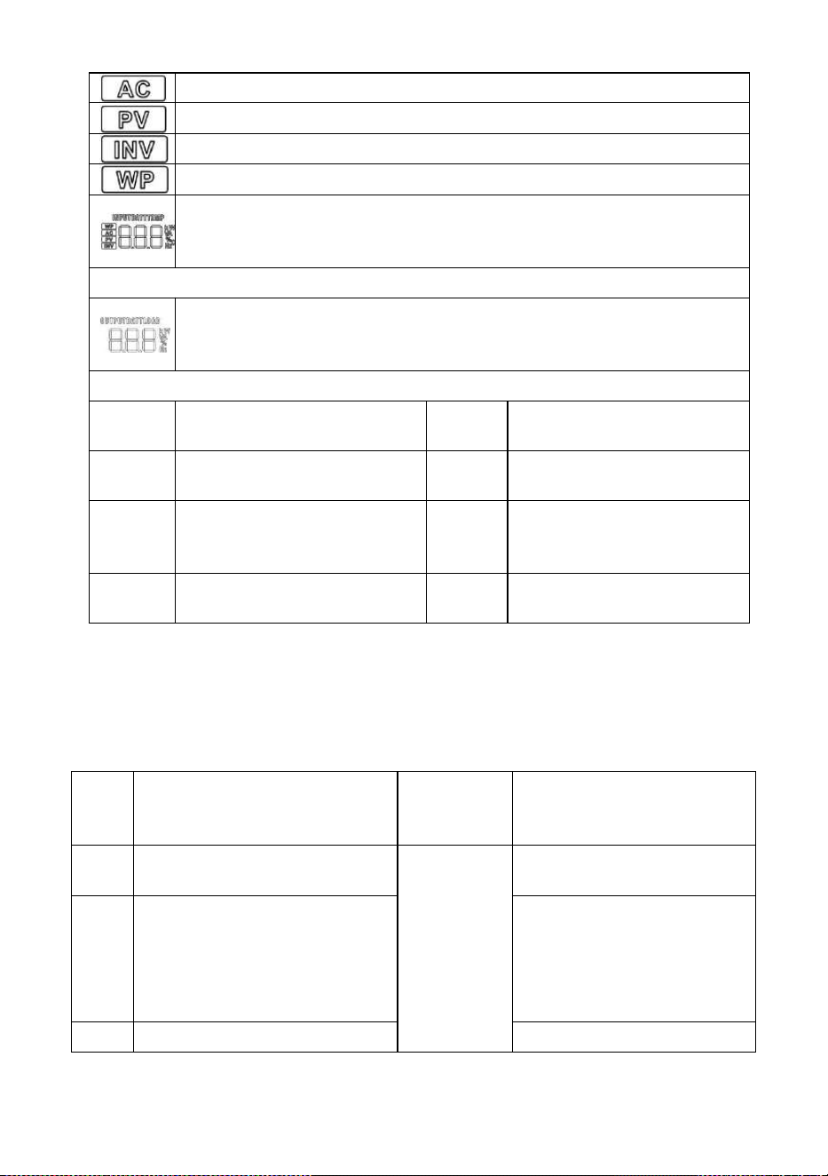
5.1 Dry node
Working principle: This dry node can control the ON/OFF of the diesel generator to
charge the battery. ① Normally, the terminals are that the NC-N point is closed
and the NO-N point is open; ② When the battery voltage reaches the low voltage
disconnection point, the relay coil is energized, and the terminals turn to that the
NO-N point is closed while NC-N point is open. At this point, NO-N point can drive
resistive loads: 125VAC/1A, 230VAC/1A, 30VDC/1A.
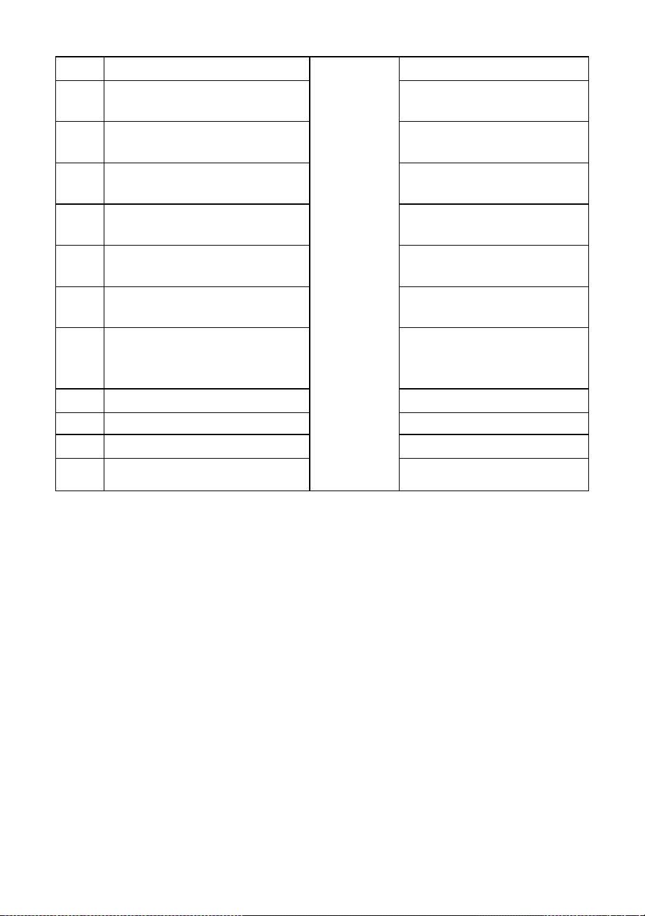
5.2 RS485 communication port
This port is an RS485 communication port which comes with two functions:
1 RS485-2 allows direct communication with the optional host computer
developed by our company through this port, and enables monitoring of the
equipment running status and setting of some parameters on the computer;
2 RS485-1/RS485-2 also allows direct connection with the optional RS485 to
WiFi/GPRS communication module developed by our company through this
port. After the module is selected, you can connect the all-in-one solar charge
inverter through the mobile phone APP, on which you can view the operating
parameters and status of the device.
As shown in the figure:
RS485-1: Pin 1 is 5V power supply, Pin 2 is GND, Pin 7 is RS485-A1, and Pin 8 is RS485-B1;
RS485-2: Pin 1 is 5V power supply, Pin 2 is GND, Pin 7 is RS485-A2, and Pin 8 is RS485-B2;
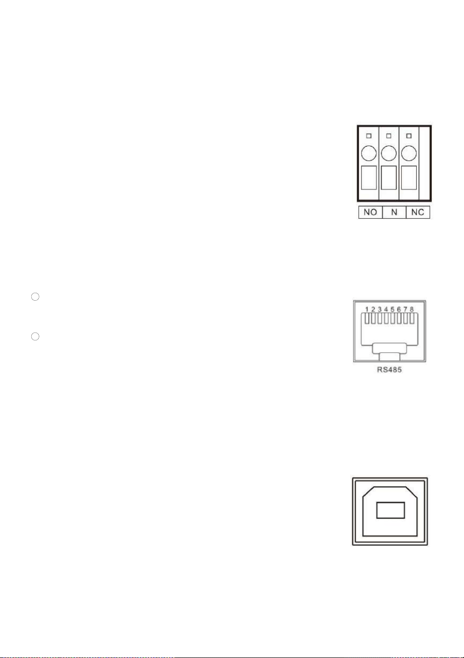
5.3 USB communication port
This is a USB communication port, which can be used for USB communication with
the optional PC host software. To use this port, you should install the
corresponding "USB to serial chip CH340T driver" in the computer.
All-in-one solar charge inverter V4.1
48
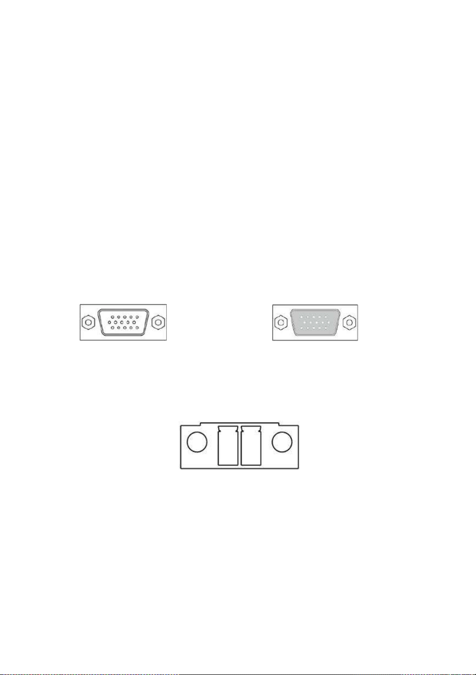
5.4 Parallel communication function (parallel operation only)
a) This port is used for parallel communication, through which the parallel modules can communicate with
each other.
b) Each inverter has two DB15 ports, one for the male connector and the other for the female connector.
c) When connecting, make sure to connect the male connector of the inverter with the female connector of
the inverter to be paralleled, or connect the female connector of the inverter to the male connector of
the inverter to be paralleled.
d) Do not connect the male connector of the inverter to its female connector.
Female connector Male connector
5.5 Current sharing detection function (parallel operation only)
a) This port is used for current sharing detection, through which the current
sharing of the parallel modules can be detected (parallel operation only).
b) Each inverter has two current sharing detection ports, which are connected in
parallel. When it is connected to other models to be paralleled, either port
can be connected for convenience. There is no special mandatory wiring

All-in-one solar charge inverter V4.1
49
requirements.
6. Protection
6.1 Protections provided
No.
Protections
Description
1
PV current/power
limiting protection
When charging current or power of the PV array configured exceeds
the PV rated, it will charge at the rated.
2
PV night reverse-
current protection
At night, the battery is prevented from discharging through the PV
module because the battery voltage is greater than the voltage of PV
module.
3
Mains input over
voltage protection
When the mains voltage exceeds 280V (230V model) or 140V (120V
model), the mains charging will be stopped and switched to the
inverter mode.
4
Mains input under
voltage protection
When the mains voltage is lower than 170V (230V model /UPS mode)
or 90V (120V model or APL mode), the mains charging will be
stopped and switched to the inverter mode.
5
Battery over
voltage protection
When the battery voltage reaches the overvoltage disconnection
point, the PV and the mains will be automatically stopped to charge
the battery to prevent the battery from being overcharged and
damaged.
6
Battery low voltage
protection
When the battery voltage reaches the low voltage disconnection
point, the battery discharging will be automatically stopped to
prevent the battery from being over-discharged and damaged.
7
Load output short
circuit protection
When a short-circuit fault occurs at the load output terminal, the AC
output is immediately turned off and turned on again after 200
milliseconds.
8
Heat sink over
temperature
protection
When the internal temperature is too high, the all-in-one machine
will stop charging and discharging; when the temperature returns to
normal, charging and discharging will resume.
9
Overload
protection
Output again 3 minutes after an overload protection, and turn the
output off after 5 consecutive times of overload protection until the
machine is re-powered. For the specific overload level and duration,
refer to the technical parameters table in the manual.

All-in-one solar charge inverter V4.1
50
10
PV reverse polarity
protection
When the PV polarity is reversed, the machine will not be damaged.
11
AC reverse
protection
Prevent battery inverter AC current from being reversely input to
Bypass.
12
Bypass over current
protection
Built-in AC input overcurrent protection circuit breaker.
13
Battery input over
current protection
When the discharge output current of the battery is greater than the
maximum value and lasts for 1 minute, the AC input would switched
to load.
14
Battery input
protection
When the battery is reversely connected or the inverter is short-
circuited, the battery input fuse in the inverter will blow out to
prevent the battery from being damaged or causing a fire.
15
Charge short
protection
When the external battery port is short-circuited in the PV or AC
charging state, the inverter will protect and stop the output current.
16
CAN
communication
loss protection
In parallel operation, an alarm will be given when CAN
communication is lost.
17
Parallel connection
error protection
In parallel operation, the equipment will be protected when the
parallel line is lost.
18
Parallel battery
voltage difference
protection
In parallel operation, the equipment will be protected when the
battery connection is inconsistent and the battery voltage is greatly
different from that detected by the host.
19
Parallel AC voltage
difference
protection
In parallel operation, the equipment will be protected when the AC IN
input connection is inconsistent.
20
Parallel current
sharing fault
protection
In parallel operation, the running equipment will be protected when
the load difference of each inverter is large due to improper
connection of current sharing line or device damage.
21
Synchronization
signal fault
protection
The equipment will be protected when there is a fault in the guidance
signal between parallel buses, causing inconsistent behavior of each
inverter.

All-in-one solar charge inverter V4.1
51
6.2 Fault code
Fault
code
Fault name
Whether it
affects the
output or
not
Description
【01】
BatVoltLow
NO
Battery undervoltage alarm
【02】
BatOverCurrSw
Yes
Battery discharge average current
overcurrent software protection
【03】
BatOpen
Yes
Battery not-connected alarm
【04】
BatLowEod
Yes
Battery undervoltage stop discharge alarm
【05】
BatOverCurrHw
Yes
Battery overcurrent hardware protection
【06】
BatOverVolt
Yes
Charging overvoltage protection
【07】
BusOverVoltHw
Yes
Bus overvoltage hardware protection
【08】
BusOverVoltSw
Yes
Bus overvoltage software protection
【09】
PvVoltHigh
No
PV overvoltage protection
【10】
PvBuckOCSw
No
Buck overcurrent software protection
【11】
PvBuckOCHw
No
Buck overcurrent hardware protection

All-in-one solar charge inverter V4.1
52
【12】
bLineLoss
No
Mains power down
【13】
OverloadBypass
Yes
Bypass overload protection
【14】
OverloadInverter
Yes
Inverter overload protection
【15】
AcOverCurrHw
Yes
Inverter overcurrent hardware protection
【17】
InvShort
Yes
Inverter short circuit protection
【19】
OverTemperMppt
No
Buck heat sink over temperature protection
【20】
OverTemperInv
Yes
Inverter heat sink over temperature
protection
【21】
FanFail
Yes
Fan failure
【22】
EEPROM
Yes
Memory failure
【23】
ModelNumErr
Yes
Model setting error
【26】
RlyShort
Yes
Inverted AC Output Backfills to Bypass AC
Input
【29】
BusVoltLow
Yes
Internal battery boost circuit failure
【30】
BatCapacityLow1
No
This function takes effect when BMS
communication is enabled. Some models
with 58-62 setting items (e.g. ASF, HES, HYP
series) will trigger this fault when the battery

All-in-one solar charge inverter V4.1
53
level is below the value of 58 items and will
automatically clear the fault when the battery
level is above the value of 58 setting items
by more than 5%.For models that do not
have the 58-62 setting items, the fault will be
triggered when the battery level is 10%.
【31】
BatCapacityLow2
No
Some models with a 58-62 setting item (e.g.
ASF, HES, HYP series) will not trigger this
fault.Other models that do not have the 58-
62 setting will trigger the fault when the
battery level falls below 5%.
【32】
BatCapacityLowSto
p
Yes
This function takes effect when BMS
communication is enabled. Some models
with the 58-62 setting item (ASF, HES, HYP
series) will trigger this fault when the battery
level is below the value of item 59 and will
automatically clear the fault when the battery
level is more than 10% above the value of
the 59 setting item.For models that do not
have the 58-62 setting item, the fault will be
triggered when the battery level is 0%.
【34】
CanCommFault
Yes
CAN communication fault in parallel
operation
【35】
ParaAddrErr
Yes
Parallel ID setting error
【36】
-
-
-
【37】
ParaShareCurrErr
Yes
Parallel current sharing fault
【38】
ParaBattVoltDiff
Yes
Large battery voltage difference in parallel
mode
【39】
ParaAcSrcDiff
Yes
Inconsistent AC input source in parallel
mode

All-in-one solar charge inverter V4.1
54
【40】
ParaHwSynErr
Yes
Hardware synchronization signal error in
parallel mode
【41】
InvDcVoltErr
Yes
Inverter DC voltage error
【42】
SysFwVersionDiff
Yes
Inconsistent system firmware version in
parallel mode
【43】
ParaLineContErr
Yes
Parallel line connection error in parallel
mode
【44】
Serial number error
YES
If the serial number is not set by omission in
production, please contact the manufacturer
to set it
【45】
Error setting of
splitphase mode
YES
【31】Settings item setting error
【58】
BMS
communication
error
NO
Check whether the communication line is
connected correctly and whether [33] is set
to the corresponding lithium battery
communication protocol
【59】
BMS alarm
NO
Check the BMS fault type and troubleshoot
battery problems
【60】
BMS battery low
temperature alarm
NO
BMS alarm battery low temperature
【61】
BMS battery over
temperature alarm
NO
BMS alarm battery over temperature
【62】
BMS battery over
current alarm
NO
BMS alarm battery over current
【63】
BMS low battery
talarm
NO
BMS alarm low battery
【64】
BMS battery over
voltage alarm
NO
BMS alarm battery over voltage

All-in-one solar charge inverter V4.1
55
6.3 Handling measures for part of faults
Fault
code
Faults
Handling measures
Display
No display on the screen
Check if the battery air switch or the PV air switch has
been closed; if the switch is in the "ON" state; press any
button on the screen to exit the screen sleep mode.
【06】
Battery overvoltage protection
Measure if the battery voltage exceeds rated, and turn off
the PV array air switch and Mains air switch.
【01】【04】
Battery undervoltage
protection
Charge the battery until it returns to the low voltage
disconnection recovery voltage.
【21】
Fan failure
Check if the fan is not turning or blocked by foreign
object.
【19】【20】
Heat sink over temperature
protection
When the temperature of the device is cooled below the
recovery temperature, normal charge and discharge
control is resumed.
【13】【14】
Bypass overload protection,
inverter overload protection
① Reduce the use of power equipment;
② Restart the unit to resume load output.
【17】
Inverter short circuit
protection
① Check the load connection carefully and clear the short-
circuit fault points; ② Re-power up to resume load output.
【09】
PV overvoltage
Use a multimeter to check if the PV input voltage exceeds
the maximum allowable input voltage rated.
【03】
Battery missed alarm
Check if the battery is not connected or if the battery
circuit breaker is not closed.
【40】【43】
Parallel connection fault
Check whether the parallel line is not connected well, such
as loose or wrong connection.
【35】
Parallel ID setting error
Check whether the setting of parallel ID number is
repeated.
【37】
Parallel current sharing fault
Check whether the parallel current sharing line is not
connected well, such as loose or wrong connection.
【39】
Inconsistent AC input source
in parallel mode
Check whether the parallel AC inputs are from the same
input interface.
【42】
Inconsistent system firmware
version in parallel mode
Check whether the software version of each inverter is
consistent.

All-in-one solar charge inverter V4.1
56
7. System maintenance
In order to maintain the best long-term performance, it is recommended to conduct
following checks twice a year.
1. Make sure that the airflow around the unit is not blocked and remove any dirt or debris from the
heat sink.
2. Check that all exposed wires are damaged by exposure to sunlight, friction with other objects
around them, dryness, bite by insects or rodents, etc., and the wires shall be repaired or replaced
if necessary.
3. Verify for the consistency of indication and display with the operation of the device. Please pay
attention to the display of any faults or errors, and take corrective actions if necessary.
4. Check all wiring terminals for corrosion, insulation damage, signs of high temperature or
burning/discoloration, and tighten the screws.
5. Check for dirt, nesting insects and corrosion, and clean up as required.
6. If the arrester has failed, replace in time to prevent lightning damage to the unit or even other
equipment of the user.
Warning: Danger of electric shock! When doing the above operations, make sure that all
power supplies of the all-in-one machine have been disconnected, and all capacitors have
been discharged, and then check or operate accordingly!
The company does not assume any liability for damage caused by:
1. Improper use or use in improper site.
2. Open circuit voltage of the PV module exceeds the maximum allowable voltage rated.
3. Temperature in the operating environment exceeds the limited operating temperature range.
4. Disassemble and repair the all-in-one solar charge inverter without permission.
5. Force majeure: Damage that occurs in transportation or handling of the all-in-one solar charge
inverter.

All-in-one solar charge inverter V4.1
57
8. Technical parameters
Models
ECO3500W(SR)
Parallel mode
Permitted parallel number
1~6
AC mode
Rated input voltage
110/120Vac
Input voltage range
(90Vac~140Vac) ±2%
Frequency
50Hz/ 60Hz (Auto detection)
Frequency Range
47±0.3Hz ~ 55±0.3Hz (50Hz);
57±0.3Hz ~ 65±0.3Hz (60Hz);
Overload/short circuit
protection
Circuit breaker
Maximum Efficiency
92%
Conversion time (bypass
and inverter)
10ms (typical)
AC reverse protection
Available
Maximum bypass overload
current
40A
Inverter mode
Output voltage waveform
Pure sine wave
Rated output power (VA)
3500
Rated output power (W)
3500
Power factor
1
Rated output voltage (Vac)
120Vac
Output voltage error
±5%
Output frequency range
(Hz)
50Hz ± 0.3Hz
60Hz ± 0.3Hz
Maximum Efficiency
91%
Overload protection
S series model:
(102% < load <125%) ±10%: report error and turn off the output after 5 minutes;
(125% < load < 150%) ± 10%: report error and turn off the output after 10 seconds;
Load >150% ±10%: report error and turn off the output after 5 seconds;
U series model:
(102% < load <110%) ±10%: report error and turn off the output after 5 minutes;
(110% < load < 125%) ± 10%: report error and turn off the output after 10 seconds;
(Load >125% ±10%): report error and turn off the output after 5 seconds;

All-in-one solar charge inverter V4.1
58
Peak power 6000VA
Loaded motor capability 2HP
Rated battery input
voltage
48V (Minimum starting voltage 44V)
Battery voltage range
Undervoltage alarm/shutdown voltage/overvoltage alarm /overvoltage recovery...
settable on LCD screen)
Power saving mode self-
consumption
Load≤50W
AC charging
Battery type Lead acid or lithium battery
Maximum charge
current(can be set)
0-40A
Charge current error ± 3Adc
Charge voltage range 40-60Vdc
Short circuit protection Circuit breaker and blown fuse
Circuit breaker
specifications
40A
Overcharge protection Alarm and turn off charging after 1 minute
PV charging
Maximum PV open circuit
voltage
145Vdc
PV operating voltage
range
60-145Vdc
MPPT voltage range 60-115Vdc
Battery voltage range 40-60Vdc
Maximum PV input power 4400W
Maximum PV input current 50A
Maximum PV charger
power
4200W
PV charging current range
(can be set)
0-80A
Maximum MPPT tracking
efficiency
99.9%
Charging short circuit
protection
Blown fuse
Wiring protection Reverse polarity protection
Hybrid charging Max charger current specifications (AC charger+PV charger)
Max charger current(can
be set)
0-120A

All-in-one solar charge inverter V4.1
59
Certified specifications
Certification
CE(IEC62109-1)/CETL(UL 1741 C22.2 NO.107.1)/FCC
EMC certification level
EN61000
Operating temperature
range
-10°C to 55°C
Storage temperature range
-25°C ~ 60°C
Humidity range
5% to 95% (Conformal coating protection)
Noise
≤60dB
Heat dissipation
Forced air cooling, variable speed of fan
Communication interface
USB/RS485(WiFi/GPRS)/Dry node control
Size (L*W*D)
426mm*322mm*124mm
Weight (kg)
10.5

ECO-WORTHY