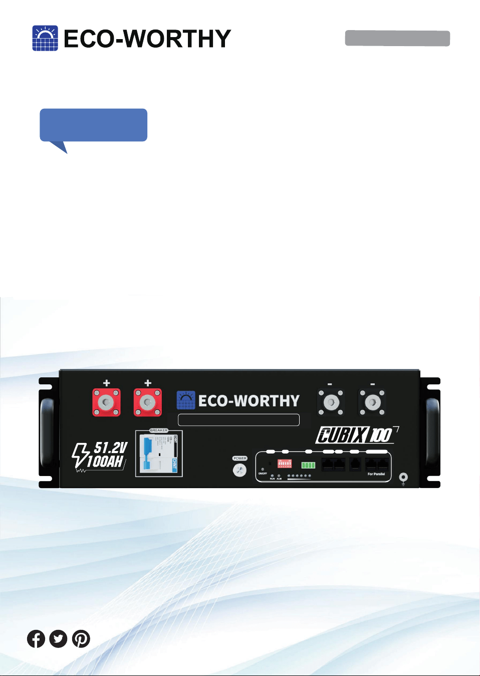
Cubix 100 Manual
Operation and Maintenance
LiFePO4
Manual Version: 4.0.0
SUPPORT
If you are experiencing technical problems and cannot find
a solution in this manual,please contact ECO-WORTHY for
further assistance.
·Call:+1 866-939-8222(US&CA)
+49 6175-6514-999(DE)
+44 7553-406-988(UK)
·Web://www.eco-worthy.com/
·E-mail: [email protected]
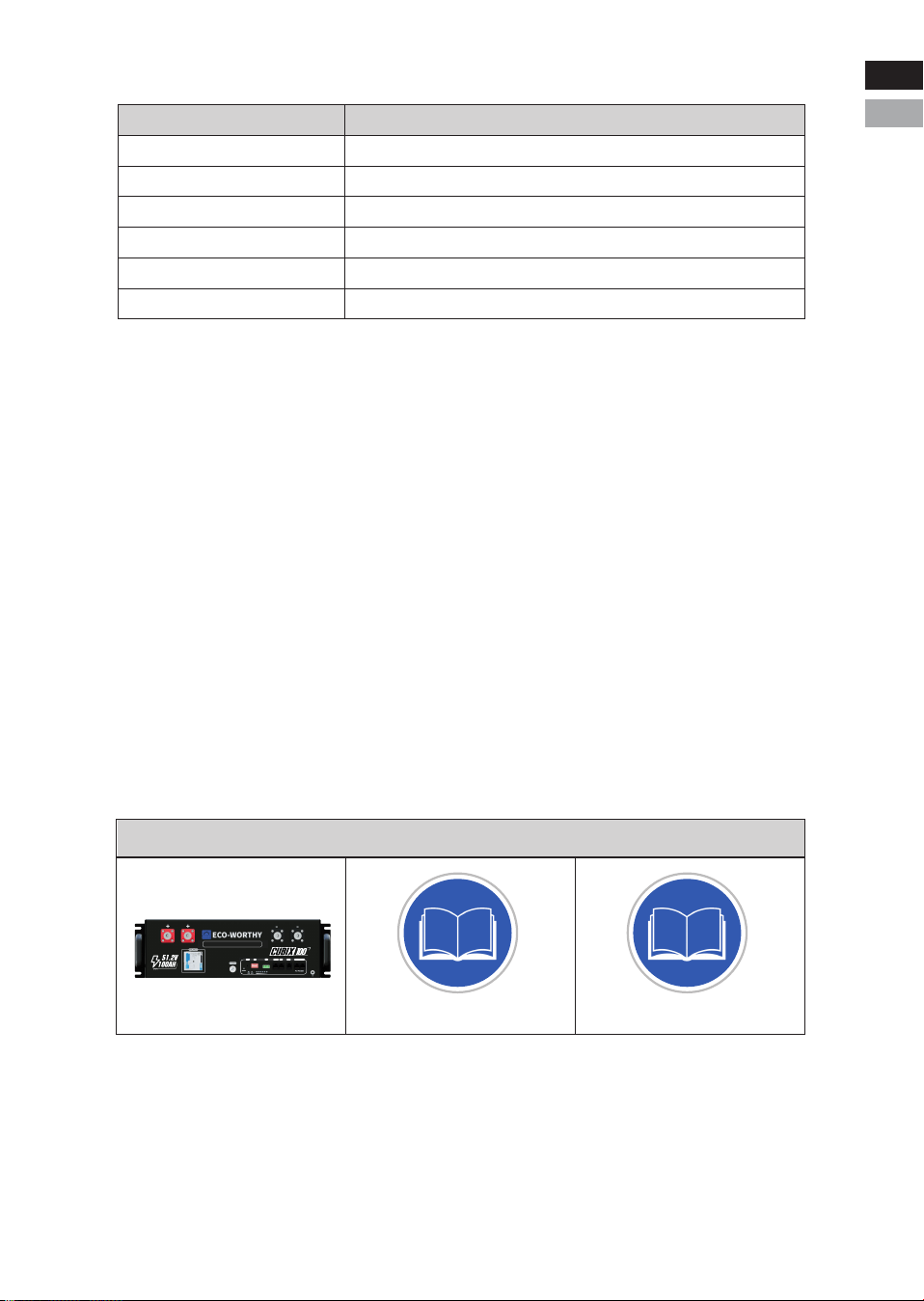
(Model: ECO-LFP4810002)
RSD
RESET ADD
RSD
RS 485-1 CAN RS232 RS485-2 RS485-3
LiFePO4 Server Rack Battery
RS485-2 RS485-3

Description
This manual describes in detail the requirements and procedures for
safe installation and operation of ECO-WORTHY lithium battery pack.
Please read this manual carefully. Only qualified persons are allowed
to install, operate and maintain the system, otherwise it may cause
product damage or personal safety risks.
Any actions against safety operation, or do not follow rules of this
manual and limited warranty letter, will void warranty and qualifica-
tion of this product. Meanwhile, the manufacturer will be not respon-
sible for the product damage, property damage, personal injury or
even death.
The information contained in this manual is accurate when it’s
issued. ECO-WORTHY reserves right to change specification (such
as optimization, upgrade or other operations) without prior notice.
In addition, please noted that the diagrams/schematics in this docu-
ment are used to help understand system configuration and installa-
tion instructions, which may be different from the actual items in the
installation.

Contents
I. Information
II. Safety
III. Product Overview
IV. Installation
V. Caution
VI. Troubleshooting
VII. Transport and Storage
VIII. Disposal of battery
IX. Technical Support
.............................................................1
.......................................................................4
..........................................................6
...........................................................19
.................................................................29
.................................................30
.....................................31
........................................31
.............................................32
1.1 Validity
This document is valid for: ECO-LFP4810002
1.2 Target Group
This document is intended for qualified persons and operators. Only
qualified persons are allowed to perform activities marked with a
warning symbol and the caption“Qualified person" in this docu-
ment. Qualified persons must have the following skills:
* Knowledge of how lithium iron phosphate batteries work and are
operated.
* Knowledge of how an energy storage system (including PV/bat-
tery/hybrid inverter, MPPT, Meter,Distribution box etc.) works and is
operated.
* Knowledge of local applicable connection requirements, standards,
and directives.
* Training in the installation and commissioning of electrical devices
and batteries.
* Training in how to deal with the dangers and risks associated with
installing, repairing and using electrical devices and batteries.
1.3 Levels of warning messages
The following levels of warning messages may occur when handling
the product.
I. Information
-1-
DANGER
Indicates a hazardous situation which, if not avoided, will result in
death or serious injury.
WARNING
Indicates a hazardous situation which, if not avoided, could result in
death or serious injury.
CAUTION
Indicates a hazardous situation which, if not avoided, could result in
minor or moderate injury or product permanent damage.
Eng
Deu.
-2-
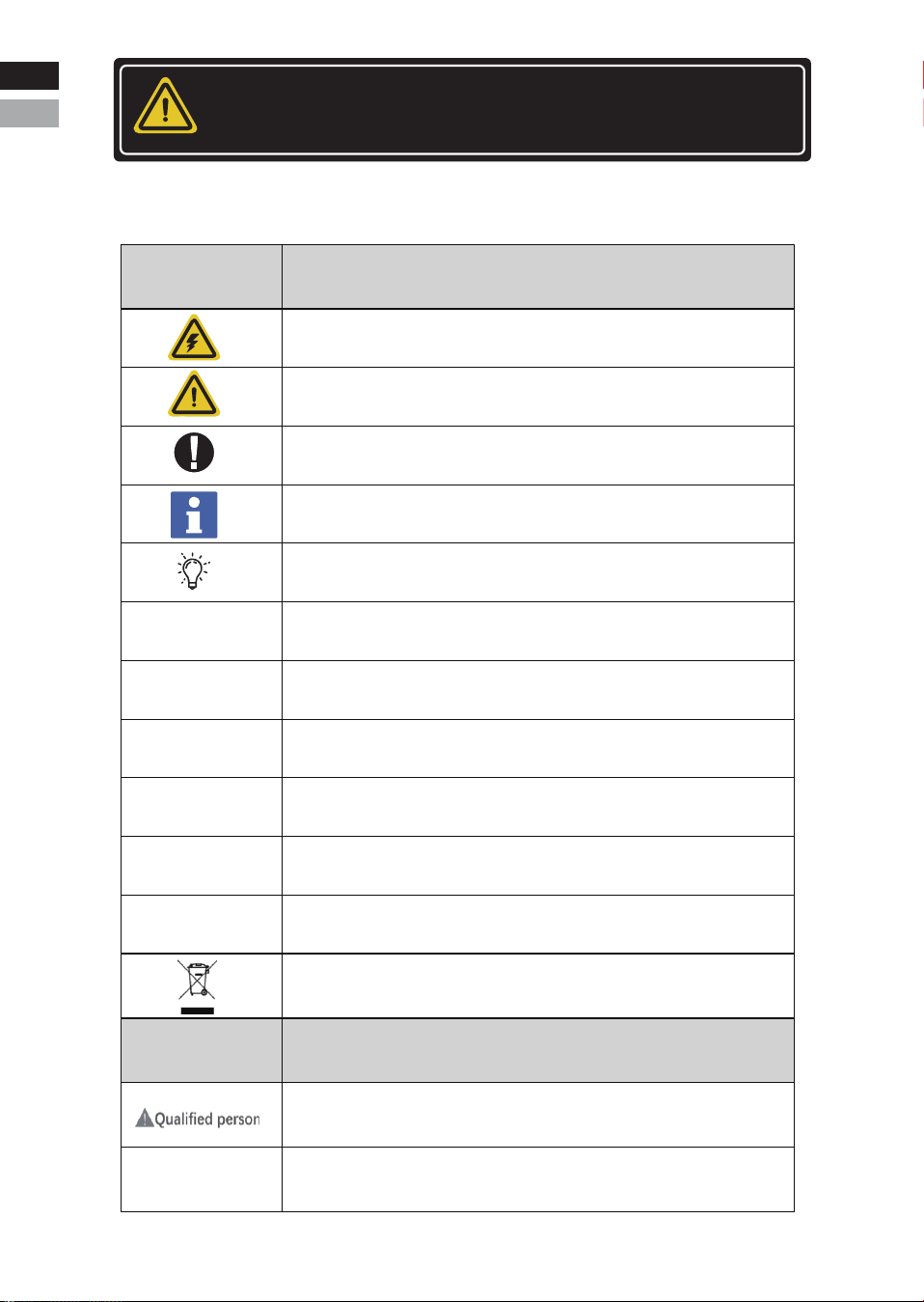
1.4 Symbol Description
NOTICE
Indicates a situation which, if not avoided, can result in property
damage or product not working or accelerated product damage.
Symbols
Definition
Indicates the danger of electric shock. If not avoided, it would
cause casualities.
WEEE designation
Indicates a potentially dangerous condition which could result in
injury or death.
Indicates important information or warnings related to concepts
talked about in the text.
Indicates more information is available in other documents relating
to the subject and reader.
Indicates important steps or tips for optimal performance.
Do not place the battery within children/pet touchable area.
Do not place the battery near heat source and flammable material.
Do not expose the battery to direct sunlight, rain and snow.
Do not short circuit the battery.
Recycle label
The UL1973 certificate label for Safety by Intertek
Label
Definition
Indicates activities that can only be performed by
qualified persons
Grounding point
Eng
Deu.

Abbreviation
Definition
Single ECO-LFP4810002 rechargeable lithium iron
phosphate battery pack including cells, BMS and
enclosure etc.
Multiple ECO-LFP4810002 battery pack connected in
parallel with power, communication and grounding
cables and installation auxiliaries.
Battery management system
Electronical Unit to ensure lithium cells’ safety and display
information or control the operation of the battery.
State of charge
The battery state of charge refers to the percentage of the
remaining capacity and rated capacity of the battery.
State of health
The battery health status refers to the percentage
between the full charged capacity and the rated capacity
of the battery.
Battery/battery
pack/battery module
Battery system/
cluster
BMS
SOC
SOH
Used to set the address of the battery in the battery packDIP switch
1.5 Abbreviation Description
-3-
Eng
Deu
Eng
Deu.
2.1 Safety precautions
2.2 Safety instructions
The battery has been designed and tested in accordance with interna-
tional (such as UL, IEC, UN38.3 etc.) safety requirements. However,
due to various factors during the whole lifetime process, ECO-WOR-
THY cannot guarantee absolute safety,in order to prevent personal
and property damage and ensure long-term operation of the battery.
Please do read and follow the section below carefully to operate the
battery and handle emergency situations.
II. Safety
-4-
•Do not impact the battery with heavy objects.
•Do not squeeze or pierce the battery pack.
•Do not throw the battery pack into the fire.
•Do not connect the battery in series.
Fire risk
•Do not expose the battery pack to the condition over 80°C.
•Do not put the battery near a heat source, such as a fireplace.
•Do not expose the battery pack to direct sunlight or raining.
WARNING
Electric shock risk
•Do not allow non-qualified person to disassemble the battery pack.
•Do not touch the battery pack with wet hands.
•Do not expose the battery pack to moisture or liquid environment.
WARNING
Damage risk
•Do not short-circuit or reverse connect the battery.
•Do not use chargers or charging devices unapproved by the manu-
facturer to charge the battery.
•Do not mix batteries from different manufacturers or different kinds,
types or brands.
•For safety, it is not recommended to use the battery near the ocean.
NOTICE
DANGER
Eng
Deu
Eng
Deu.
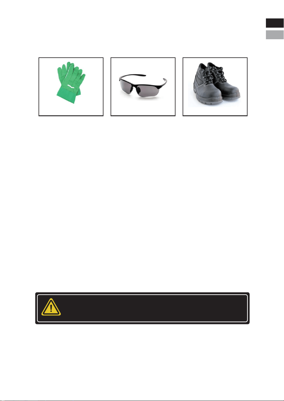
2.2.1 Safety gear
It is required to wear the following safety gear when installing and
handling the battery pack.
2.2.2 Emergency safety measures
* Water invasion
Please cut off the AC power supply of the system first and then
disconnect all switches under the premise of ensuring safety.
* Electrolyte or gas leakage
If the battery pack leaks electrolyte, avoid contacting with the leaking
liquid or gas. If one is exposed to the leaked substance, immediately
perform the actions described below.
• Gas Inhalation: Evacuate the people from the contaminated area
and seek medical aid immediately.
• Eye Contact: Flush your eye with clean and flowing water for 15
min, and then seek medical aid immediately.
• Skin Contact: Thoroughly rinse the exposed area with soap and
water to be sure no chemical or soap is left on them, and seek medical
aid immediately.
• Ingestion: Induce vomiting, and seek medical help immediately.
-5-
WARNING
In case of fire situations, please use carbon dioxide fire extinguisher
rather than liquid to put out fires.
Insulated gloves Safety Glasses Safety Shoes
Eng
Deu
Eng
Deu.
2.2.3 Other Tips
• All the product are strictly inspected before shipment.Please
contact us for replacement if you notice there are any defectives such
as swelling etc.
• Do not disassemble batteries and components, otherwise the man-
ufacturer will not be responsible for any damage caused by unautho-
rized disassembly or repair.
• Enable the battery to be safely grounded before use to make sure
the system in safe and normal operation.
• Please ensure that the electric parameters of these devices are
compatible mutually before connecting the battery to other devices.
• Please take the environmental factors into careful considerations to
ensure that the system can work in a suitable condition as the envi-
ronment and storage methods have a certain impact on the service
life and reliability of this product.
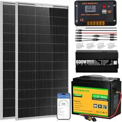
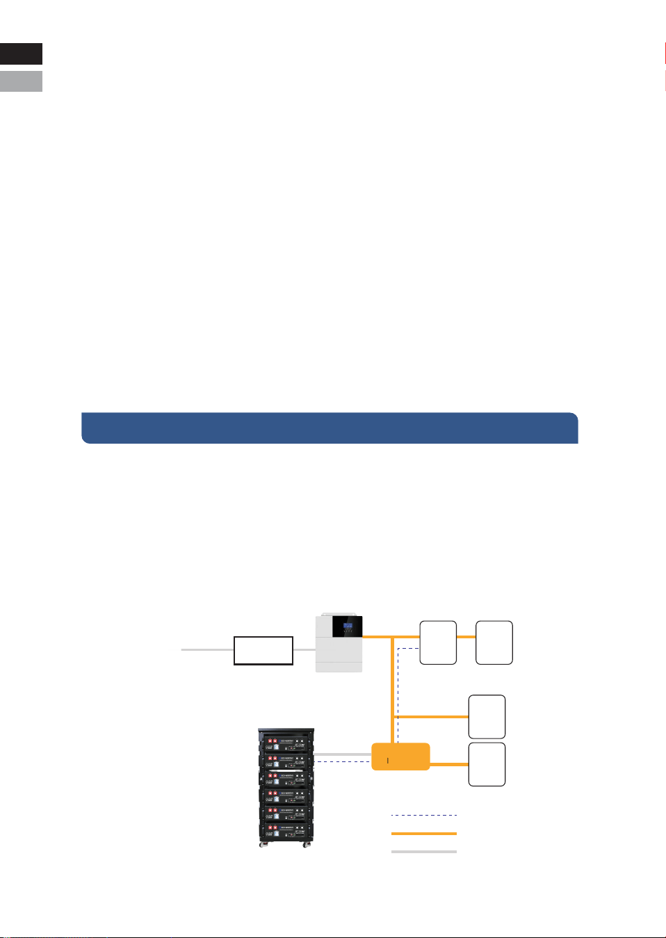
3.1 Introduction
The ECO-LFP4810002 battery is designed for residential application
and works as a storage unit in the photovoltaic system. It is a 48V
Li-ion battery storage system, with BMS inside itself. It could be oper-
ated in both on-grid, back-up and off-grid modes with compatible
inverters. Below is the general schematic of an ac-coupled system.
III.Product Overview
-6-
PV Panel
PV INV
Meter Grid
General Load
Back-up Load
Communication Cable
AC connection
DC connection
Combiner box
Battery
Inverter
Eng
Deu
Eng
Deu.

3.2 Features
• Equipped with shunt release, the safety performance is improved to
a higher level.
• With highest safety, battery is made from LiFePO4 chemistry and
complies with highest international safety and transport standard.
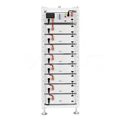
• Modular and flexible, it can support up to 32 batteries connected
together to expand the system energy.
• Built-in pre-charge circuit to avoid rush current when connecting
with different inverters/chargers.
• Automatic dynamic addressing function when connecting multiple
batteries together.
• It can support a maximum of 96% DOD under off-grid and back-up
application.
• Built-in BMS provides warning and protection functions including
over-discharging, over-charging, over- current, short-circuit and
high/low temperature.
• LiFePO4 is equipped with automatic balancing function to meet
long cycle life. New batteries need to go through multiple charge -
cycles (approximately 10 times) to reach their maximum capacity.
• Compact size and light weight for easy installation and mainte-
nance.
• CAN/RS485 port for external communication.
-7-
This electrical connection in this diagram is only for illustration.
Please follow the manual suggestions of related devices and
operate in accordance with locally applicable connection
requirements, standards, and directives.
CAUTION
Eng
Deu
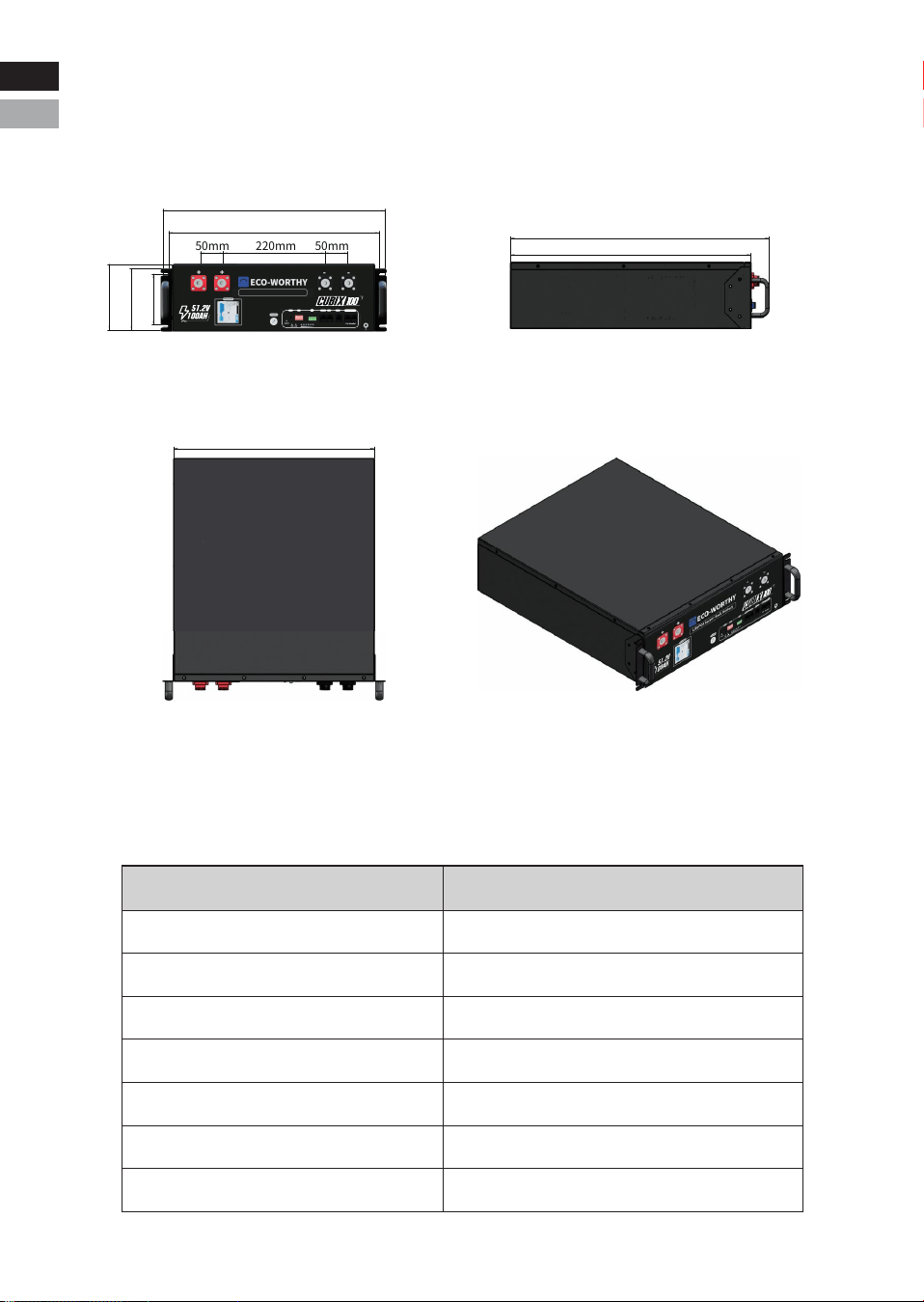
3.3 Specification
3.3.1 Dimension
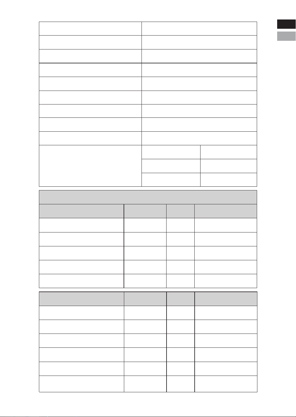
3.3.2 Parameters
-8-
Items
Rated voltage
Max. voltage range
Charge voltage
Low voltage cut-off
Nominal energy
Usable energy
Nominal capacity
51.2V
40~58.4V
58.4V
40.0V
5.12KWh
5.12KWh
100Ah
ECO-LFP4810002
483mm
143mm
50mm 220mm 50mm
133mm
457mm
110mm
435mm
522mm
561mm
Eng
Deu
Eng
Deu.
RSD
RESET ADD
RSD
RS 485-1 CAN RS232 RS485-2 RS485-3
LiFePO4 Server Rack Battery
RS485-2 RS485-3
-9-
Dimension
Weight
Standard charge current
Max. charge current
Standard discharge current
Max. discharge current
Communication port
Max. parallel number
Operating temperature
Storage temperature
22.09*19.02*5.63in/56.1*48.3*14.3cm
103lbs/47kg
100A
RS485 /CAN/RS232
32pcs
Environment at the
shipment state
Less than 1 year
less than 3 months
60±25%R.H.
≤50A
≤50A
100A(initial temp. ≤35℃)
Charge: 0~55℃
-20~25℃
20~40℃
Discharge: -20~55℃
BMS Parameters
Charge
Cell Voltage Protection
Module Voltage Protection
Charge Over Current 1
Charge Over Current 2
Temperature Protection
Spec
3650mV
58.4V
120A
130A
Delay
3000mS
3000mS
2000mS
500mS
/
Recovery
3400mV
54.4V
<32℉/0℃ or
>149℉/65℃
Discharge
Cell Voltage Protection
Module Voltage Protection
Discharge Over Current 1
Discharge Over Current 2
Short Circuit
Temperature Protection
Spec
2500mV
40.0V
120A
140A
1200A
Delay
3000mS
3000mS
2000mS
200mS
400uS
/
Recovery
3000mV
48.0V
<-4℉/-20℃ or
>149℉/65℃
>-4℉/-20℃ or
<14℉/-10℃
>41℉/5℃ or
<122℉/50℃
Eng
Deu
Eng
Deu.
RSD
RESET ADD
RSD
RS 485-1 CAN RS232 RS485-2 RS485-3
LiFePO4 Server Rack Battery
RS485-2 RS485-3
-10-
BMS
PCB Temperature Protection
Cell Balance
Temperature Accuracy
Cell Voltage Accuracy
Current Accuracy
SOC
>221℉/105℃
±3℃
±10mV
±2%
5%
≤20uA
≤200uA
≤50mA
Condition
For Cells
Storage/Transport
Sleeping
Charging/Discharging
RS485、CAN、RS232
≥49 feet/15m
Communication Ports
Bluetooth&Wifi Signal Distance
Power Consumption
60mV charging
equalization
Parameter
Off Mode
Sleep Mode
Operating Mode
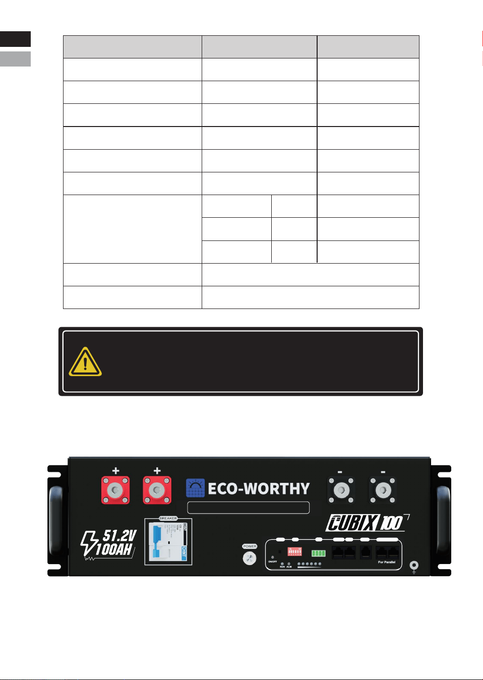
3.3.3 Panel Interface
NOTICE
The optimum operating temperature range is from 15°C to 30°C.
Frequent exposure to the harsh temperatures may worsen the
performance of the battery pack and its cycle life.
A
B
D
E
F G H I J K
C
L
PN
O
M
A
Q
Eng
Deu
Eng
Deu.

NO.
A
B
C
D
E
F
G
H
I
J
K
L
M
N
O
P
Q
Items
Handles
Positive terminal
Negative terminal
Power switch
Reset
ADD
RSD
RS485-1
CAN
RS232
ON/OFF indicator
RUN
ALM
SOC
Grounding
Remark
Usage description
For handling,intallation and
disasembly of battery
Used to connect the inverter/charger
Used to connect the inverter/charger
Over-current protection &
BMS Second level of protection
Used to Power on/off BMS
Used to reset the BMS
Used to set the address of
the battery in the battery pack
The two interfaces on the left are connected to the
emergency stop switch. When the emergency stop
switch is closed, the air switch is disconnected.
Connect to host computer/inverter
Connect to inverter
Connect to host computer/inverter
For communicaton between batteries
Baud rate 9600
Baud rate 9600
Baud rate 19200
4 open holes for fixing
battery on the rack
Connected in series
to the positive busbar
Indicates whether the battery is
turned on or off
Used to show battery is in
running status when lighting or flashing
Used to show battery Alarm/
Protection status
Used to show battery real-time SOC
Used to connect battery with ground
-11-
125A breaker &
shunt release
RS485-2
RS485-3
Eng
Deu
Eng
Deu.
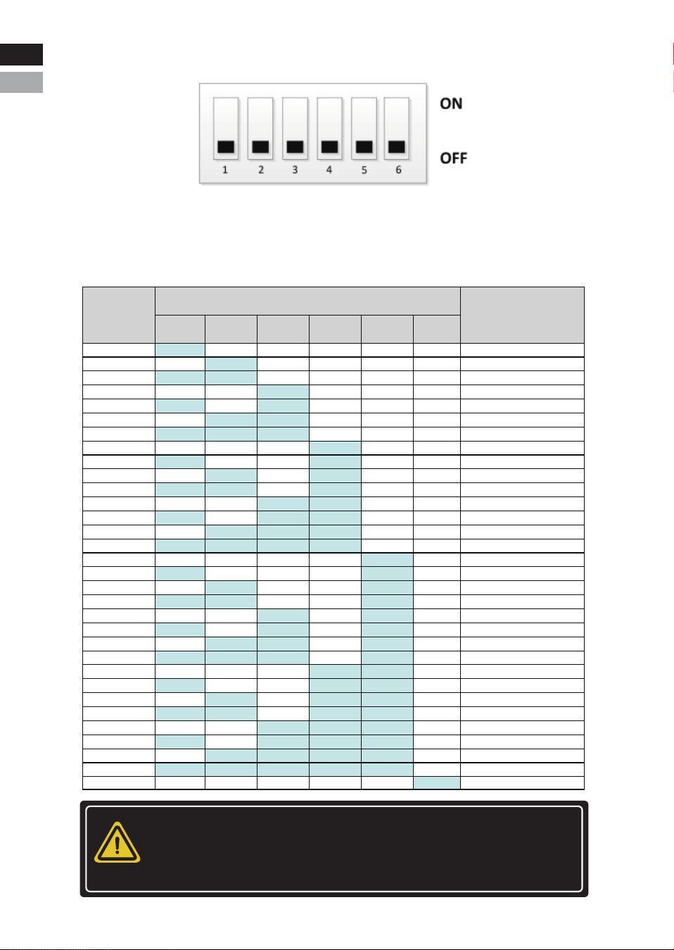
3.3.3.1 : ADD
By setting the address through the dip switch on the BMS to distin-
guish different PACKs, it is necessary to avoid setting the address to
be the same. The definition of the BMS dip switch refers to the table
below, and the system supports a maximum of 32 parallel machines.
-12-
Failure to follow the DIP switch setting will cause the communica-
tion fault between battery and inverter. For detailed settings
with different inverter/charger, please contact your supplier
or ECO-WORTHY for consultation.
NOTICE
1
2
3
4
5
6
7
8
9
10
11
12
13
14
15
16
17
18
19
20
21
22
23
24
25
26
27
28
29
30
31
32
ON
OFF
ON
OFF
ON
0FF
ON
OFF
ON
OFF
ON
OFF
ON
OFF
ON
OFF
ON
OFF
ON
OFF
ON
OFF
ON
OFF
ON
OFF
ON
OFF
ON
OFF
ON
OFF
OFF
ON
ON
OFF
OFF
ON
ON
OFF
OFF
ON
ON
OFF
OFF
ON
ON
OFF
OFF
ON
ON
OFF
OFF
ON
ON
OFF
OFF
ON
ON
OFF
OFF
ON
ON
OFF
OFF
OFF
OFF
ON
ON
ON
ON
OFF
OFF
OFF
OFF
ON
ON
ON
ON
OFF
OFF
OFF
OFF
ON
ON
ON
ON
OFF
OFF
OFF
OFF
ON
ON
ON
ON
OFF
OFF
OFF
OFF
OFF
OFF
OFF
OFF
ON
ON
ON
ON
ON
ON
ON
ON
OFF
OFF
OFF
OFF
OFF
OFF
OFF
OFF
ON
ON
ON
ON
ON
ON
ON
ON
OFF
OFF
OFF
OFF
OFF
OFF
OFF
OFF
OFF
OFF
OFF
OFF
OFF
OFF
OFF
OFF
ON
ON
ON
ON
ON
ON
ON
ON
ON
ON
ON
ON
ON
ON
ON
ON
OFF
OFF
OFF
OFF
OFF
OFF
OFF
OFF
OFF
OFF
OFF
OFF
OFF
OFF
OFF
OFF
OFF
OFF
OFF
OFF
OFF
OFF
OFF
OFF
OFF
OFF
OFF
OFF
OFF
OFF
OFF
OFF
ON
SET TO PACK1 (Master)
SET TO PACK2
SET TO PACK3
SET TO PACK4
SET TO PACK5
SET TO PACK6
SET TO PACK7
SET TO PACK8
SET TO PACK9
SET TO PACK10
SET TO PACK11
SET TO PACK12
SET TO PACK13
SET TO PACK14
SET TO PACK15
SET TO PACK16
SET TO PACK17
SET TO PACK18
SET TO PACK19
SET TO PACK20
SET TO PACK21
SET TO PACK22
SET TO PACK23
SET TO PACK24
SET TO PACK25
SET TO PACK26
SET TO PACK27
SET TO PACK28
SET TO PACK29
SET TO PACK30
SET TO PACK31
SET TO PACK32
4 5 6321
Battery
ID
ADD Settings
Explain
Eng
Deu
Eng
Deu.

3.3.3.2 Communication Interface Pin Diagram
The communication protocols/devices/software supported by
each ports
-13-
PIN
1,8
2,7
4
5
Pin
Description
Communication
Port
Functional
Description
Connect to host
computer/inverter
RS485-1 CAN RS232 RS485-2 RS485-3
Connect to host
computer/inverter
Connect to host
computer
Parallel
communication
Description
RS485-B1
RS485-A1
NC
NC
GND
PIN
1,8
2,7
4
5
3,63,6
Description
NC
NC
CANH1
CANL1
GND
PIN
1,2
3
4
5
6
1,8
2,7
4,5
3
6
Description
NC
TX
RX
GND
14V
RS485-B2
RS485-A2
NC
RSD
GND
3.3.3.3 Reset
654321
RS485-1 CAN RS232
8 7 6 5 4 3 2 1 8 7 6 5 4 3 2 1
8 7 6 5 4 3 2 1 8 7 6 5 4 3 2 1
RS485-2 RS485-3
PORT
USAGE
SUPPORT
RS485-1 CAN RS232
Connect to the inverter or upper computer
Connect to the inverter
JBD-UP
Solar Assistant
Overkill
Connect to the
upper computer
PYLON-LV RS485 V3.5 2019/
08/07 (9600)-(Default)
Pylon CAN bus protocol
V2.0.6_220510-(Default)
Growatt BMS CAN-Bus-
protocol-low-voltage-V1.04
Growatt Low voltage battery
BMS V1.09(1) -20201022
BMS Status
Sleep mode
Active mode
Active mode
Operation LED indicator System
Protection
board activated
System entered
sleep mode
Protection
board reset
Press the button(3~6
seconds) and release
Press button(1 second)
and then release
The LED indicators light up first, then turn off in
sequence: MOS -> RUN -> ALM -> SOC6 -> SOC1
The LED indicators light up in sequence: SOC1 -> SOC6 -
> ALM -> RUN -> MOS, each indicator lights up for 0.5 seconds
The LED indicators display
according to the current power level
Press the button(6~10
seconds) and release
VOLTRONIC-485-V1.0.3-200325
LXP-485-V1.0.0-210625
Goodwe-CAN-V1.7-220228
Sofar-CAN-V1.00-211117-Rev6
Victron-CAN-V1.00-210107
Deye-485 Modbus Protocol(4)-
deye-V1.30-20160801
SRNE_WOW_PACE_BMS_Modbus_
Protocol_for_RS485_V1.3(2020-11-24)
Luxpowertek Battery CAN
Protocol-V1.0-20200211
Deye-Low voltage battery
CAN -V1.0-20220402
Ginlong-Low voltage
battery CAN Protocol
SMA-CAN_V1.0.0-210630-
FSS-ConnectingBat-TI-en-20W
VMII-Low voltage battery
CAN Protocol-V1.4
SRNE_WOW_BMS_Modbus_
Protocol_for_CAN_V1.0
INVT-BMS and PCS
CAN Protocol V1.00
Lithium Battery Protocol GT
Version December 22 Version 1.0
SAKO-485 Inverter and BMS
communication Protocol(2022-01-07)
PIN
Description
Eng
Deu
Eng
Deu.
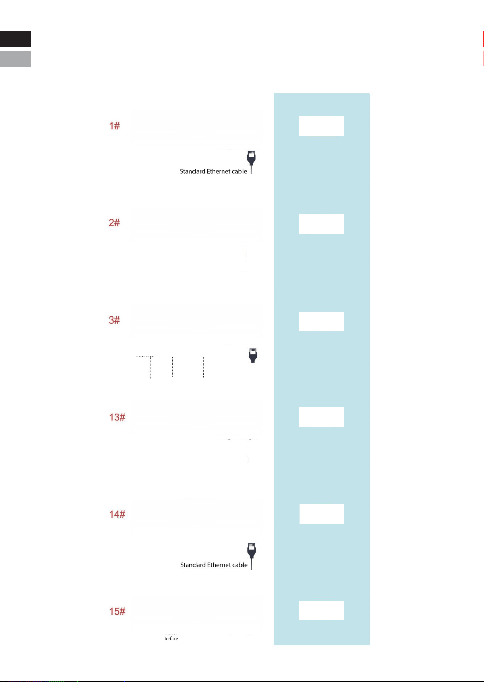
3.3.3.4 Parallel Wiring Instructions
-14-
Example of parallel
dialing method
654321
16 15 14 13 12 11 10 9
RS485-1 CAN RS232
8 7 6 5 4 3 2 1
16 15 14 13 12 11 10 9 8 7 6 5 4 3 2 1
RS485-2 RS485-3
654321
16 15 14 13 12 11 10 9
RS485-1 CAN RS232
8 7 6 5 4 3 2 1
16 15 14 13 12 11 10 9 8 7 6 5 4 3 2 1
RS485-2 RS485-3
654321
16 15 14 13 12 11 10 9
RS485-1 CAN RS232
8 7 6 5 4 3 2 1
16 15 14 13 12 11 10 9 8 7 6 5 4 3 2 1
RS485-2 RS485-3
654321
16 15 14 13 12 11 10 9
RS485-1 CAN RS232
8 7 6 5 4 3 2 1
16 15 14 13 12 11 10 9 8 7 6 5 4 3 2 1
RS485-2 RS485-3
654321
16 15 14 13 12 11 10 9
RS485-1 CAN RS232
8 7 6 5 4 3 2 1
16 15 14 13 12 11 10 9 8 7 6 5 4 3 2 1
RS485-2 RS485-3
654321
16 15 14 13 12 11 10 9
RS485-1 CAN RS232
8 7 6 5 4 3 2 1
16 15 14 13 12 11 10 9 8 7 6 5 4 3 2 1
RS485-2 RS485-3
Connect RS485-2 to the RS485-2 port of the next
battery. Connect RS485-3 to the RS485-3 port of
the next battery.
Eng
Deu
Standard Ethernet cable
Standard Ethernet cable
Eng
Deu.

3.3.3.5 LED Description
LED Indicator Light Colors
-15-
Color Green Green Red
ON/OFFName RUN ALM
SOC(LED1~6)
LED1
Green
LED2
Green
LED3
Green
LED4
Green
LED5
Green
LED6
Green
LED Indicator Light Status Display
SOC Indicator Status (Battery Level)
Status
On
Off
Slow Flash
Fast Flash
Medium Flash
Description
The light stays on continuously.
The light stays off continuously.
The indicator turns on for 0.25S and off for 3.75S.
The indicator turns on for 0.5S and off for 0.5S.
The Indicator turns on for 0.5S and off for 1.5S.
Charging State
LED
Charging State Indicator Logic Discharging State Indicator Logic
0~16.6%
16.6~33.2%
33.2~49.8%
49.8~66.4%
66.4~83.0%
83.0~100%
SOC
RUN On Medium Flash
LED1
Off
Off
Off
Off
Off
LED2
Off
Off
Off
Off
On
LED3
Off
Off
Off
On
On
LED4
Off
Off
On
On
On
LED5
Off
On
On
On
On
LED6
On
On
On
On
On
LED1
Off
Off
Off
Off
Off
On
LED2
Off
Off
Off
Off
On
On
LED3
Off
Off
Off
On
On
On
LED4
Off
Off
On
On
On
On
LED5
Off
On
On
On
On
On
LED6
On
On
On
On
On
On
Fast
Flash
Fast
Flash
Fast
Flash
Fast
Flash
Fast
Flash
Fast
Flash
Eng
Deu
Eng
Deu.

LED Indicator Light Description
-17-
Important Notes:
1. Alarm: The ALM light alerts you to issues that may limit the invert-
er's charging or discharging current.
2. Standby Warning: The warning state in standby mode is triggered
first by an alarm, then the device enters standby mode.
SOC(LED1~6) Description
System
Status
Shutdown
State
Standby
State
Event
Sleep
RUN ALM
LED1
Off
LED2
Off
LED3
Off
LED4
Off
LED5
Off
LED6
Off
On
Off
On
Off
On
Off
On
Off
On
Off
On
Off
Indicator lights
are all off
/
/
/
/
/
/
Stop charging
Stop charging
Stop charging
Stop charging
Stop charging
ON/
OFF
Off Off Off
Off
Off
Off
Off
Off Off Off Off Off Off
OffOff
Off Off
Off
Off Off Off Off Off
Off Off Off Off Off Off
On
On
On On
On
On
Off On
On
On
On
On
On
On
On On
On
Off
Normal
Warning
Indicate according to SOC status
Indicate according to SOC status
Indicate according to SOC status
Slow Flash
Medium
Flash
Medium
Flash
Medium
Flash
Medium
Flash
Medium
Flash
Slow Flash
Normal
Warning
Over-voltage
protection
Over-cur-
rent,
High/Low
temperature
Over-cur-
rent,
Short-cir-
cuit,
High/Low
temperature
Single cell
disconnect,
Tempera-
ture probe
disconnect,
AFE
sampling
failure,
Discharge
MOS failure
Normal
Warning
Under-voltage
Protection
Charging
State
Discharging
State
Failure
State
Eng
Deu
Eng
Deu.

3.4 Protection
-18-
Items Description Remark
Charge End
Cell/
PACK
high-voltage
The BMS will stop charging if any cell or PACK
voltage reaches the protection value and it will be
auto-released only when both Pack and cell voltage
back to the release voltage range or there is
efficient discharge current.
Discharge End
Cell/
PACK
low-voltage
The BMS will stop discharging if any cell or PACK
voltage is under the protection value and it will be
released only when all the cell voltage back to the
release voltage range or there is efficient charge
current.
It can automatically recover.
Please charge timely, otherwise it
may be in Low-power mode to be
over-discharged.
High
temperature
The BMS will halt charging, discharging, or both if
any cell, environment, or MOSFET temperature falls
outside the acceptable range.
Automatic recovery
Low
temperature
The BMS will stop charging or discharging or
both if any cell/environment/MOS temperature is
under the range.
Automatic recovery
Charge
over-current
The BMS will stop charging when the charging current
is higher than the protection value. And it will
release from the protection when the system delays
time is met.
It can automatically recover. If
locked after three consecutive
times, manual intervention is
required.
Discharge
over- current/
Overload
The BMS will stop discharging when the discharging
current is higher than the protection value. And it
will release from the protection when the system
delays time is met.
Automatic recovery. If locked after
three consecutive times, manual
intervention is required.
Short-circuit/
Reversed
Short-circuit and Reversed polarity protection
happened
Charge to release Manual reset
Temperature,
Voltage,
Current sensor
failure
When entering the failure mode, manual intervention
is required; no charging and discharging.
Manual intervention
Dormancy mode
After reaching a certain condition, it will be in the
dormancy mode.
Recoverable
Eng
Deu
Eng
Deu.
IV. Installation
CAUTION
Please re-charge the battery via solar, grid/generator or other
energy source within 24h if the battery is over-discharged.
NOTICE
Manually short-circuiting and reversing the battery will void the
warranty.
4.1 Preparation
4.1.1 Safety Compliance
The system installation must be finished by qualified person(s).
During the whole installation process, please strictly follow the
local safety regulations and related operating procedures.
4.1.2 Environment
The operating environment shall meet the following requirements:
-19-
Category
Working temperature
Relative humidity
Altitude
Safety requirement
Description
5%~90%, No condensation
<3000m
•Do not expose the battery to direct sunlight, rain and snow.
•Do not place the battery within children/pet touchable area.
•Do not place the battery near heat source and flammable material.
•Do not place the battery in a closed place where the ventilation is
not available.
•Do not drop, deform, impact, cut or spearing with a sharp object.
•Do not put heavy things on battery.
•Do not disassemble the battery without Manufacturer's permission.
•No conductive dust and water or other liquid to contact battery.
•Follow the emergency measure if there is water invasion or
electrolyte and gas leakage.
•Contact your supplier within 24 hours if any product failure happens.
Eng
Deu.
-20℃-55℃(maximum operating range)
15℃-30℃ (optimal temperature)
Area restriction
This product is not suitable for use near the ocean.
Eng
Deu
4.2 Inspection
4.2.1 Unpack precautions
* Please load and unload it in accordance with the specified
requirements to prevent sun and rain when you receive the equip
ment.
* Please check and confirm the goods (such as quantity, appear
ance, etc.) according to the "scope of delivery " before unpack
ing.
* Do light take and put during unpacking process to protect the
surface coating of the object;
* Please record and contact to the manufacturer if the inner
packing is damaged after unpacking.
Tools
Screwdriver (slot, cross)
Wrench
Diagonal pliers
Needle nose pliers
Clamping pliers
Wire stripper
General materials
BMS & APP Quick Start*1PCS Manual *1pcs Battery Pack *1pcs
Multi-meter
Clamp meters
Insulating tape
Thermometer (observe the installation environment)
Anti-static bracelet
Cable ties
4.1.3 Tools
-20-
Eng
Deu
Eng
Deu.
RSD
RESET ADD
RSD
RS 485-1 CAN RS232 RS485-2 RS485-3
LiFePO4 Server Rack Battery
RS485-2 RS485-3
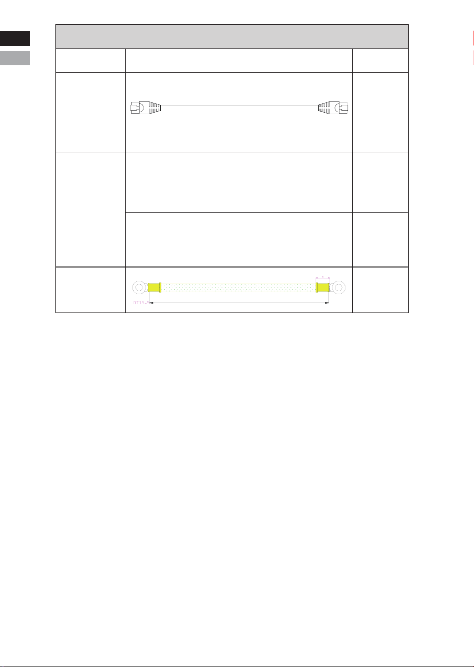
Cables
Type Details Qty.
Version II(CAN):
1PCS
A: Battery to Battery positive cable(2AWG 150mm RED)
B: Battery to Battery negetive cable(2AWG 150mm BLACK)
Parallel
Cables
Grounding
Cable
1PCS
1PCS
1PCS
Battery to
Battery
Communica-
tion Cable
150mm
200mm
150mm
Eng
Deu
Eng
Deu.
200mm
-22-
NOTICE
Keep the unused cable pins NULL to avoid affecting the closed
loop communication.
NOTICE
A ground connection of communication cable may be required from
some inverters. Please follow the rules from inverter manufacure.
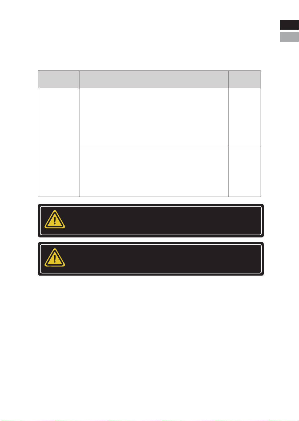
4.2.2 External cable
Cables connected to inverter or junction box belong to External
Cable kits. It is NOT included in battery carton. Customers need
buy it separately, and the information are as below.
Cables
C: Battery to Inverter positive cable(2/0AWG 2000mm RED)
D: Battery to Inverter negetive cable(2/0AWG 2000mm BLACK)
Qty.DetailType
1PCS
1PCS
Eng
Deu
Eng
Deu.
CAUTION
Injuries may result if the product is lifted incorrectly or dropped
while being transported or mounted. Wear suitable personal
protective equipment for all work on the product.
CAUTION
Ensure that no lines are laid in the wall which could be damaged
when drilling holes.
4.3 Start Installation
4.3.1 Remainder
Please check again whether the following conditions or equipment
meet the requirements before installation:
* Check if there’s enough space for installation, and if the load-bear-
ing capacity of the bracket or cabinet meets the weight requirements;
* Check whether the power cable pair(s) used meets the maximum
current requirement for operation;
* Check whether the overall layout of power supply equipment and
batteries at the construction site is reasonable;
* Check whether the installer is wearing anti-static wristband;
* Check whether there’re two people on the construction site for
installation work;
* Check if there’s potential risks at location of installation site, e.g
flooding, sun exposure, corrosion,and salt spray.
4.3.2 Procedures
-23-
Qualified person
Eng
Deu
Eng
Deu.
NOTICE
For any other installations, please avoid the battery directly
contacting the ground and avoid of high salinity, humidity to
prevent the product from rusting and corrosion.
-24-
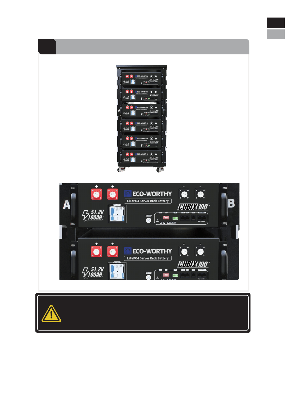
4.3.2.1 Install the Battery
1
Insert the Battery into the Rack Slot
Eng
Deu.
Eng
Deu
-21-
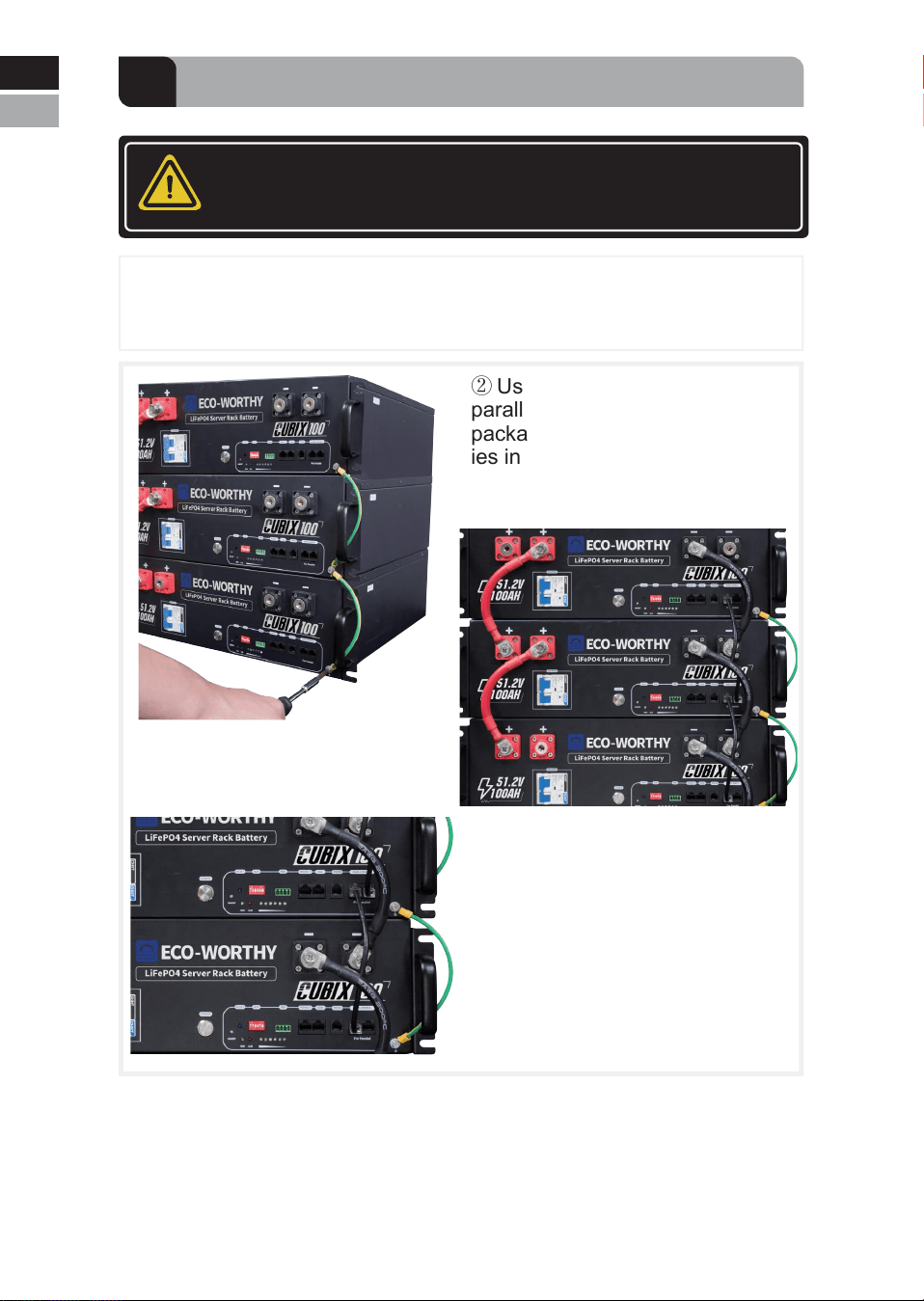
Warning
First, ensure that the circuit breaker is in the off position on the left,
and the POWER switch is off.
-25-
① Use the grounding wire included in the packaging to connect the
casings of all batteries in series.
2
Connect the batteries in parallel
③ Connect the batteries with the
battery communication wires.
Note: Connect RS485-2 port to
RS485-2 port or RS485-3 port to
RS485-3 port between batteries
② Use the 2AWG 200mm battery
parallel wires included in the
packaging to connect the batter-
ies in parallel.
Eng
Deu.
Eng
Deu
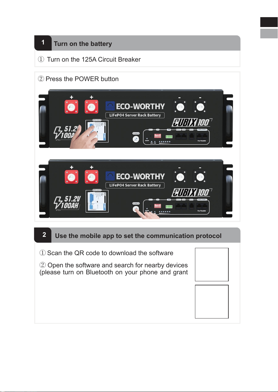
① Turn on the 125A Circuit Breaker
1
Turn on the battery
② Open the software and search for nearby devices
(please turn on Bluetooth on your phone and grant
Bluetooth permissions)
③ Modify the Inverter Protocol on the Parameter
page(For more detailed information, please refer to
APP-Quick Start)
① Scan the QR code to download the software
② Press the POWER button
2
Use the mobile app to set the communication protocol
-26-
4.3.2.2 Set the inverter communication protocol
Eng
Deu
Eng
Deu.
-27-
Note: Please turn off the POWER button and the breaker before
connecting the cables. Use the cables required by the inverter to
connect the battery pack to the BAT input terminal of the inverter.
This battery integrates multiple inverter communication protocols (see
page 13 for details). The default communication protocol is PYLON,
which is compatible with most brands of inverters. The supported
mainstream brands are: SRNE, VICTRON, DEYE, LUXPOWER,
GOODWE......
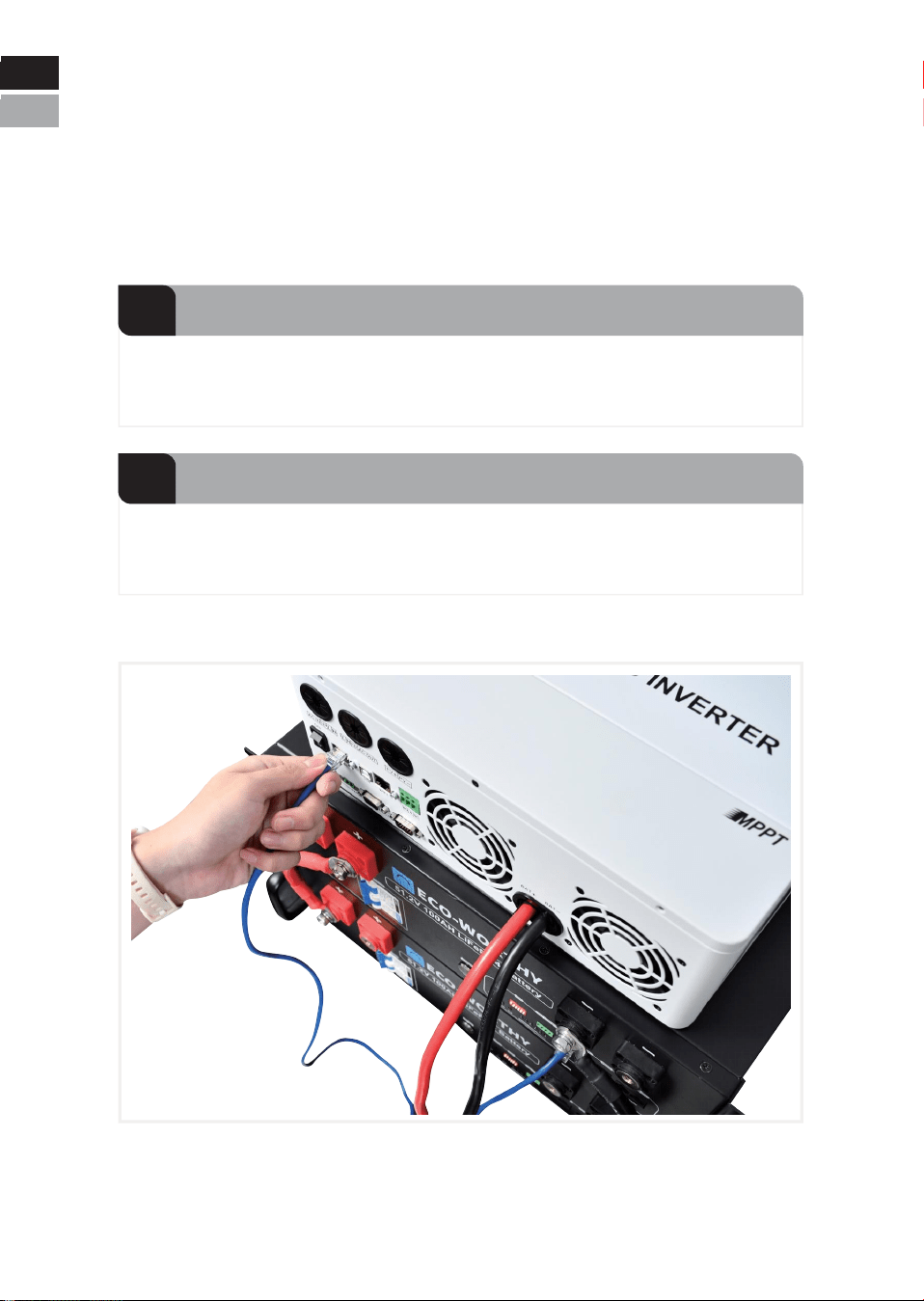
1
Battery-inverter power connection
Use a standard Ethernet cable to connect the battery's RS485-1 or
CAN port to the BMS communication port of the inverter.
2
Battery-inverter communication connection
4.3.2.3 Connect the battery to the inverter
Eng
Deu
Eng
Deu.
CAUTION
Confirm inverter AC input and PV input are disconnected before
wiring connection, and the DC/ signal switch of inverter/charger
is in off status.
NOTICE
The maximum communication cable length is required to be less
than 15m between inverter/charger and battery.
The maximum power cable length is suggested to be less than 10m
between inverter/charger and battery.
NOTE
Choose the suitable breaker considering the inverter power/current,
rated voltage, and tripping characteristic etc.
CAUTION
The maximum tolerance current of each power cable and terminal is
125A, and 100A for continuously is suggested. Please use correspond-
ing number of power cable pairs according to the field configuration and
local connection requirements, standards, and directives.
-28-
Eng
Deu
Eng
Deu.
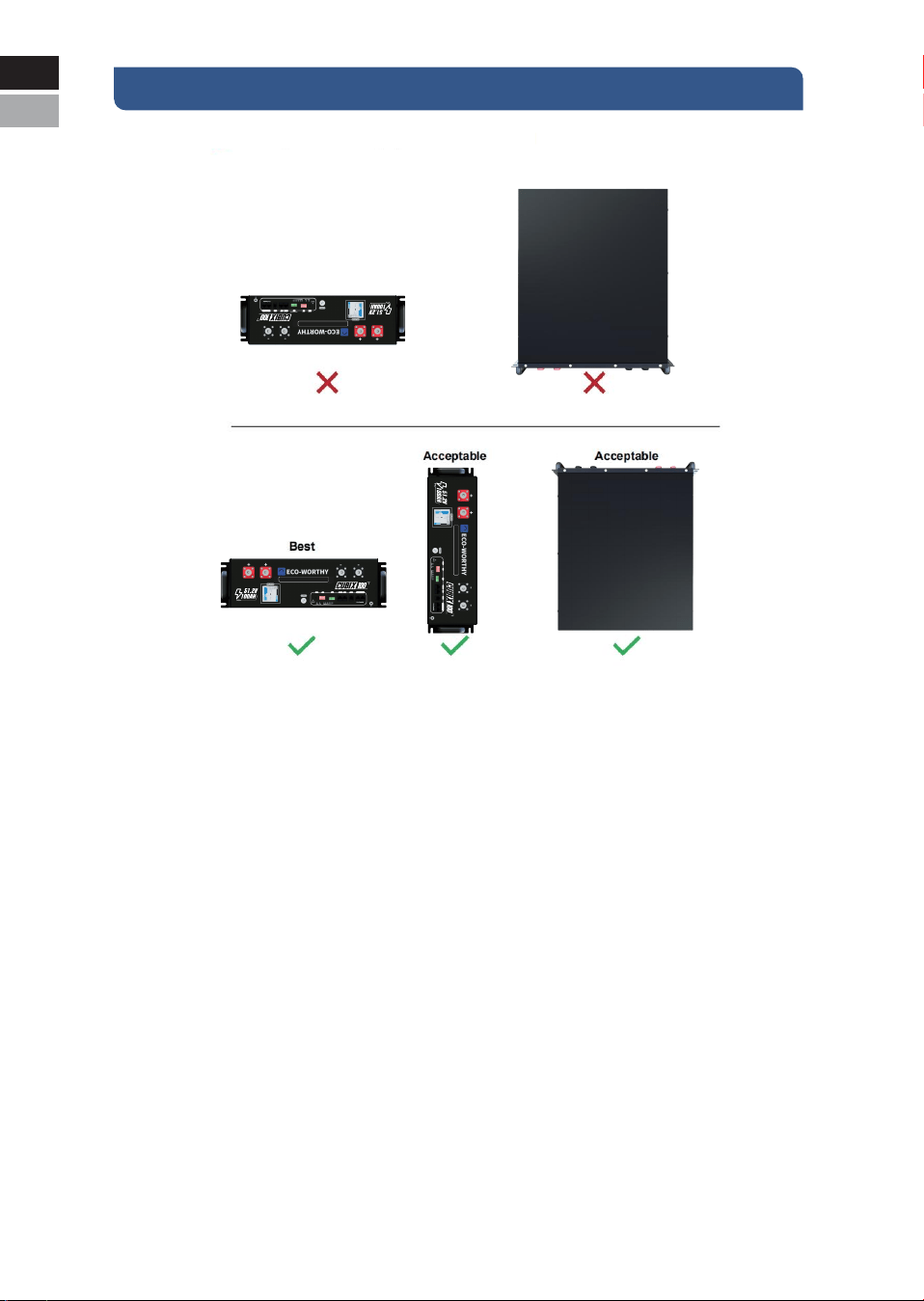
V. Caution
CAUTION:
Never position the battery upside down or face down!
-29-
Eng
Deu
Eng
Deu.
RSD
RESET ADD
RSD
RS 485-1 CAN RS232 RS485-2 RS485-3
LiFePO4 Server Rack Battery
RS485-2 RS485-3
RSD
RESET ADD
RSD
RS 485-1 CAN RS232 RS485-2 RS485-3
LiFePO4 Server Rack Battery
RS485-2 RS485-3
RSD
RESET ADD
RSD
RS 485-1 CAN RS232 RS485-2 RS485-3
LiFePO4 Server Rack Battery
RS485-2 RS485-3
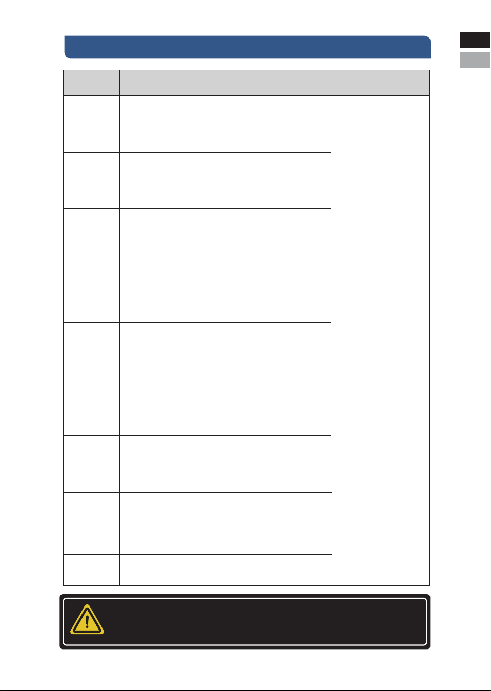
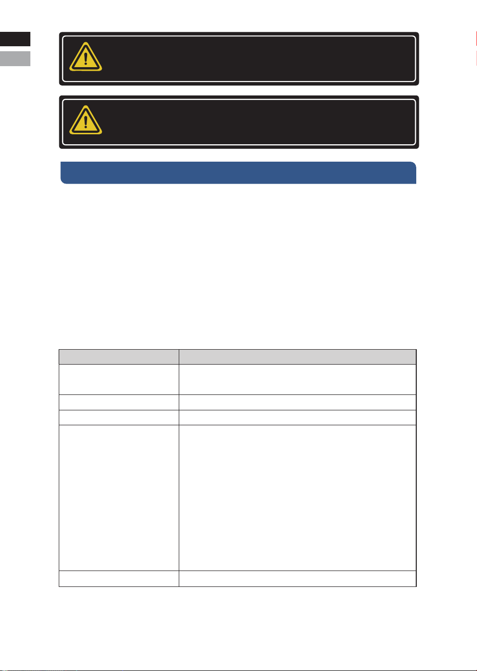
VI. Troubleshooting
Items Solution Measure
Unable to start
1. Switch on battery and press RESET for 6s to observe
whether the battery can be started.
2. Charge the battery with a charge or inverter to provide
54~57.6V voltage and observe whether it can be started.
Unable to
charge
1. Check whether the cable connection between the battery
and the inverter/charger is correct.
2. Check whether the inverter/charger setting is correct.
3. Check whether the battery is in charge protection mode; if
yes, try to discharge the battery.
Eng
Deu.
If the abnormal status is
still alive after these
steps, please contact your
supplier.
If there is any other
situation(s) excluding in this
table, turn off the faulty
battery, and contact your
supplier.
Unable to
discharge
1. Check whether the cable connection between the battery
and the inverter/charger is correct.
2. Check whether the battery occurs short circuit, reverse
connection, pre-charge failure during connection inverter etc.
3. Check whether the battery is in discharge protection
mode; if yes, try to charge the battery.
High/Low
temperature
1. Stop the battery system for a while, and check whether the
installation location temperature meets the requirement.
2. Avoid continuous full charging and discharging.
High current
Check whether the configuration and parameters setting on
the inverter/charger is correct.
ALM ON
Turn off all the batteries, and remove the fault battery from the
system.
Communica-
tion fail
ALM and RUN
indicator lights
flash
continuously
The BMS
cannot
communicate
The ON/OFF
indicator does
not light up
1. Check whether the communication cable type is correct and
is contacted well.
2. Check whether the DIP switch setting is correct.
3. Check whether the inverter protocol related setting is correct.
4. Check whether both battery and inverter are working properly.
There is a problem with the battery software and the firmware
needs to be updated. Please contact the supplier to obtain the
update method.
There is a problem with the battery software and the firmware
needs to be updated. Please contact the supplier to obtain the
update method.
Please contact the supplier for repair documentation.
NOTICE
Please restart after software is upgraded.
-30-
Eng
Deu

Eng
Deu.
VII. Transport and Storage
* Do not violently shake, impact or squeeze, and prevent sun and rain
during the transportation.
* Do light take and put and strictly prevent falling, rolling, and heavy
pressure during loading and unloading.
* The battery should be placed in a dry, clean, dark, and well-ventilat-
ed indoor environment for long- term storage, and the recommended
storage temperature range is 15~30℃ .
* No harmful gases, flammable and explosive products and corrosive
chemical substances in the storage location.
* The batteries should be stored and transported in close to 50% SOC,
and do not store over 80% SOC for long time.
* The battery needs to be charged every 6 months if it is not used for a
long time.
* No fall down, no pile up over 6 layers, and keep face up.
VIII. Disposal of battery
Disposal of battery must comply with the local applicable disposal
regulations for electronic waste and used batteries. Please review your
local battery recycling or management regulations or contact
ECO-WORTHY for more information.
-31-
Eng
Deu

IX. Technical Support
7.Renoly Support
-32-
Youtube: @ecoworthy
Facebook: https://www.facebook.com/ecoworthy.store/
Tiktok: https://www.tiktok.com/@eco_worthy
3) Customer service telephone numbers:
Eng
Deu.
+49 6175-6514-999Tel(DE):
+1 866-939-8222Tel(US&CA):
+44 7553-406-988Tel(UK):
Note:
Customer Service Hours:
Mon-Fri 8:30 AM - 6:00 PM(CST)US:
Mon-Fri 9:00 AM - 5:00 PM(GMT)UK:
Mon-Fri 9:00 AM - 5:00 PM(CET)DE:
Address(US): 4411 East State Hwy D Suite C Springfield, Missouri 65809
Address(DE): ECO-Worthy Europe GmbH Otto-Hahn-Str. 20 61381 Fried-
richsdorf - Köppern Germany
2) Company address: USA/Germany
1) Customer service email:
E-mail: essvipsupport@eco-worthy.com.cn
4) Official website address:
Web: https://www.eco-worthy.com/
5) Official social media:
Eng
Deu

ECO-WORTHY