
��V/��V/��V/��V
��A MPPT
MANUAL
Installation and Operation Manual
Controller
Version: �.�
SUPPORT
If you are experiencing technical problems and cannot
find a solution in this manual,please contact ECO-WOR-
THY for further assistance.
·Call:+� ��� ��� ����(US/CA)
+�� ���� ������(UK)
+�� ���� ���� ���(DE)
·Web://www.eco-worthy.com/
·E-mail: customer.service@eco-worthy.com
PV
BAT
LOAD
ERROR

Contents
Ⅰ. Important Safety Instructions
Ⅱ. Product Overview
Ⅲ. Installation Instructions
Ⅳ. Working principle and operation guide
Ⅴ. Common faults and handling
Ⅵ. Specification
VII. Technical Support
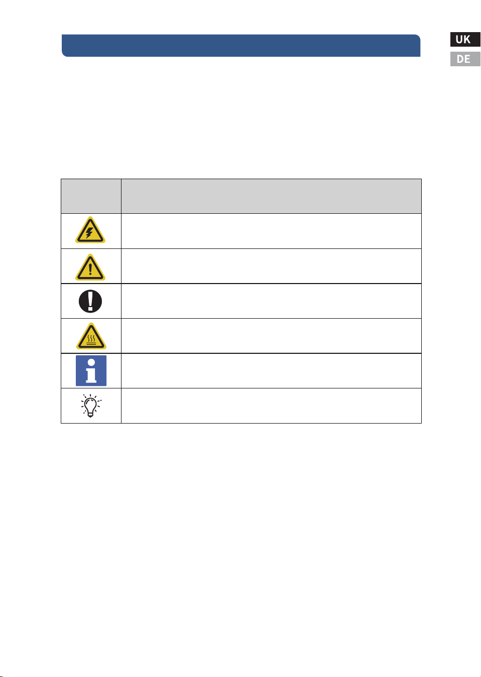
�.� Key Indicator Symbols
�.� Security Information
�.� Installation Safety Precautions
�.� Battery Safety
�.� Product Characteristics
�.� Optional accessories
�.� Installation Precautions
�.� Installation Steps
�.� The maximum power point tracking technology
�.� Charge status and parameters
�.� Load Control
�.� LED Indicators
�.� Display and key operation
�.� Key operation
............................................................�
.....................................................................................�
.........................................................................................�
.......................................................................�
......................................................................................................�
.......................................................................................�
....................................................................................�
.........................................................................................�
..........................................................................�
..................................................................................�
.............................................................................................�
.....................................��
.....................................��
......................................................................��
...................................................................................................��
................................................................................................��
.............................................................................��
...................................................................................................��
..........................................................��
...............................................................................................��
...................................................................................��
It is recommended to keep this manual.This manual contains import-
ant safety, installation and operation instructions for the MPPT solar
controller.
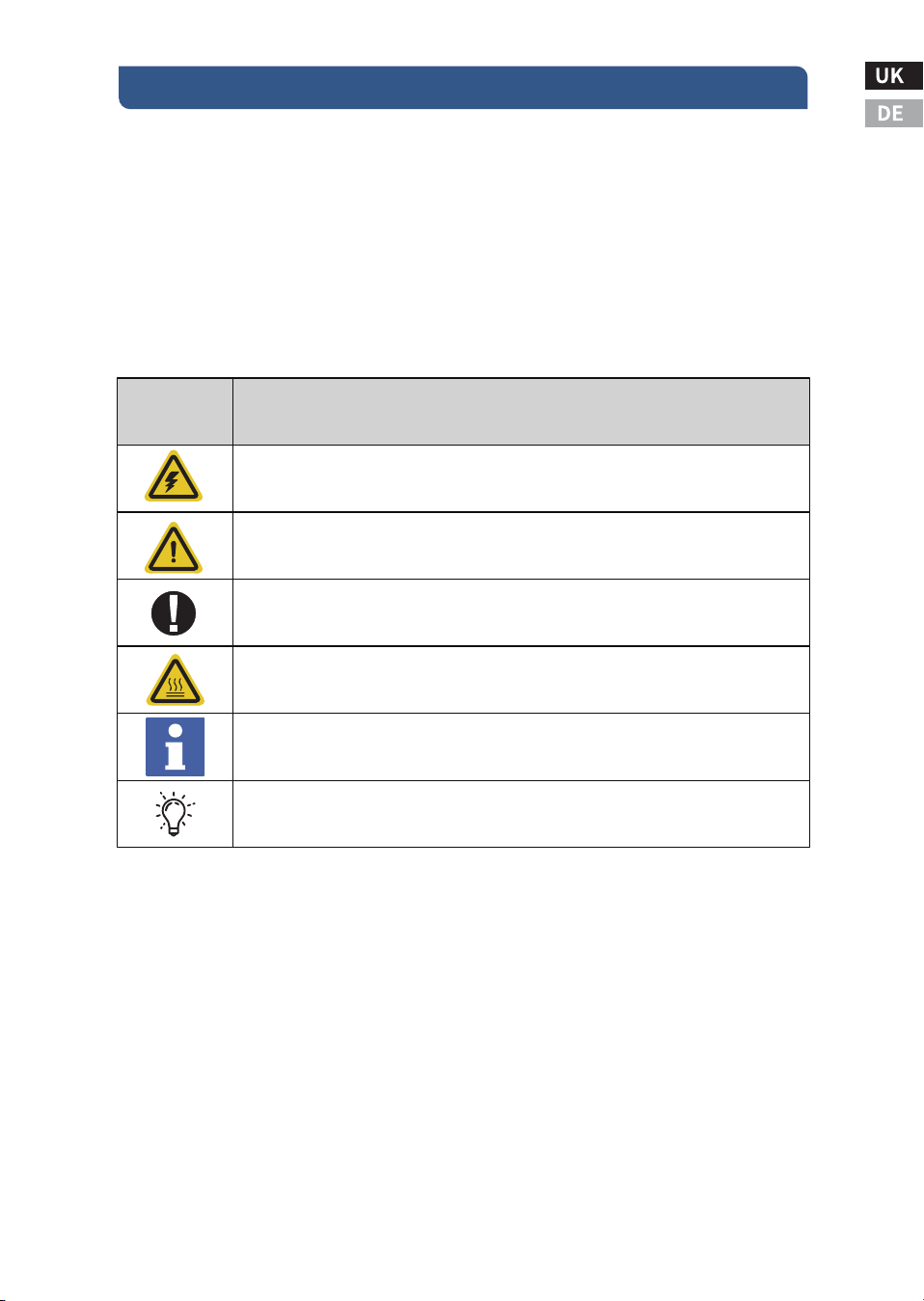
�.� Key Indicator Symbols
The following symbols are used in this manual to indicate potentially
hazardous conditions or to mark important safety instructions:
�.� Security Information
● Before installation, read all the instructions and precautions in this
manual.
● There are no user repairable parts in the MPPT. Do not disassemble
or attempt to repair the controller.
Ⅰ. Important Safety Instructions
-�-
Indicates the danger of electric shock. If not avoided, it would
cause casualities.
Indicates a potentially dangerous condition which could result in
injury or death.
Indicates important information or warnings related to concepts
talked about in the text.
Indicates more information is available in other documents relating to
the subject and reader.
Indicates important steps or tips for optimal performance.
Symbols
Definition
WARNING HOT SURFACE: Indicates the risk of high temperature, if not
avoided, would cause scalds.

-�-
● Requires disconnection of external solar power and battery.
●Disconnect all power from the controller before installing or
adjusting the MPPT.
�.� Installation Safety Precautions
● Install MPPT indoors. Keep hands off the components and ensure
no water enters the controller.
● Mount the MPPT in a location that is out of reach to avoid acciden-
tal contact. MPPT heat sinks can get very hot during operation.
● When using batteries, please use insulated tools.
● Avoid wearing jewelry during installation.
● The battery pack must consist of batteries of the same type, brand
and age.
● Do not smoke near the battery pack.
● Power connections must be kept tight to avoid overheating due to
loose connections.
● Use appropriately sized wires and circuit breakers.
● Grounding can be performed at the bottom fixing holes of the
chassis.
● The MPPT controller must be installed by a qualified technician in
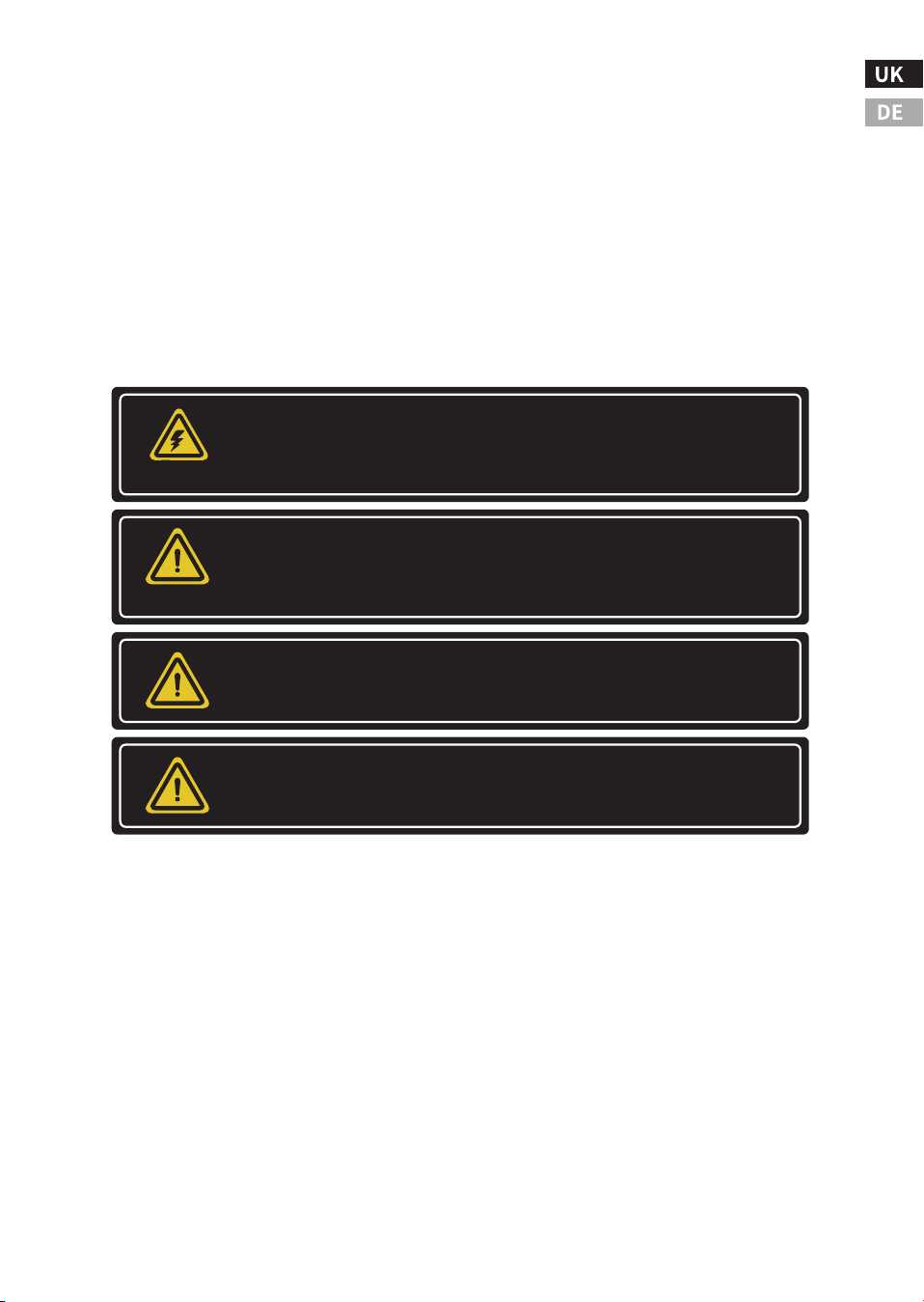
Danger of electric shock. No power or other terminals are
galvanically isolated from the DC input and may be energized
with dangerous solar voltages. Under specific malfunctions,
the battery could become overcharged. Before making
contact, test the impedance between all terminals and
ground.
WARNING
The communication port of the controller is not an isolated
source or isolated signal. Please be careful when connecting
with other devices.
WARNING
There is no GFDI (Ground Fault Detection Device) inside the
controller.
WARNING
● A mechanism to disconnect all power electrodes should be incor-
porated. Ensure these disconnects are part of the permanent wiring
system.
● The MPPT's positive power terminal should be connected in a
common positive configuration. If required, ground the system
according to the provided instructions, local codes, and regulations.
● The MPPT enclosure's grounding point must be securely connect-
ed to a reliable ground wire.
● The grounding conductor should be firmly secured to prevent any
accidental disconnection.
● Battery repairs should be carried out or overseen by individuals
who are knowledgeable about batteries and the necessary safety
measures.
● Be very careful when using large lead-acid batteries. Wear safety
goggles and have fresh water available to prevent contact with
battery acid.
● Remove watches, rings, jewelry and other metal objects before
using the battery.
● Wear rubber gloves and boots.
● Use tools with insulated handles and avoid placing tools or metal
objects on top of the battery.
-�-
Batteries may present a risk of electric shock or burn due to high
short-circuit current, fire or explosion of exhaust gas. Please follow
proper precautions.
WARNING
Danger of explosion. Batteries need to be disposed of properly. Do
not dispose of batteries in a fire. Refer to local regulations or codes
for requirements.
WARNING
Note: When replacing batteries, use the correctly specified quantity,
size, type and rating based on the application and system design.
Note: Do not open or damage the battery. The electrolytes released
are harmful to the skin and may be toxic.

● Disconnect the solar panel or other charging power source before
connecting or disconnecting the battery terminals.
● Check if the battery has been inadvertently grounded. If it has,
immediately eliminate the ground connection.Be aware that contact
with any part of a grounded battery can cause an electric shock.To
mitigate the risk of such shocks, ensure the battery is not grounded
during installation and maintenance, especially for equipment with-
out a grounded power circuit or in the case of remote battery power
systems.
● Please read the battery manufacturer's instructions carefully
before installing / connecting the MPPT or removing the battery from
the MPPT.
● Avoid creating a short circuit with the cables attached to the
battery.
● If an accident occurs, seek help from someone nearby.
● Explosive battery gas may exist during charging. Make sure there is
adequate ventilation to release the gas.
● No smoking in the battery area.
● If battery acid comes into contact with skin, wash with soap and
water. If acid contacts eyes, flush with fresh water and seek medical
attention.
● Before starting to charge the lead-acid battery, make sure that the
battery electrolyte level is correct. Do not attempt to charge a frozen
battery.
● When placing the battery, pay attention to recycling the battery.
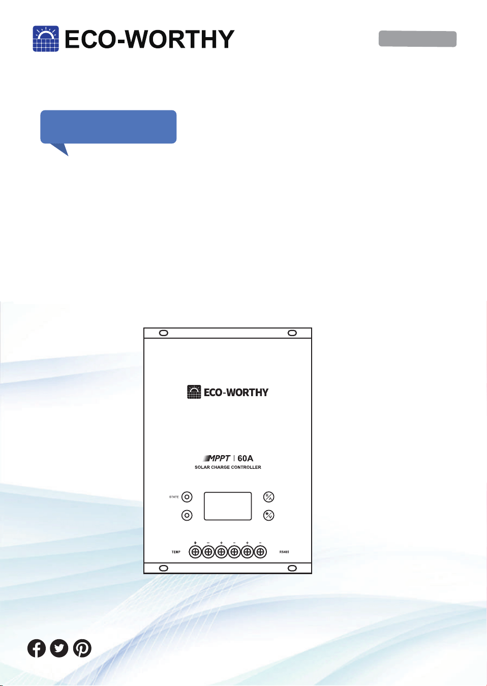
�.� Product Characteristics
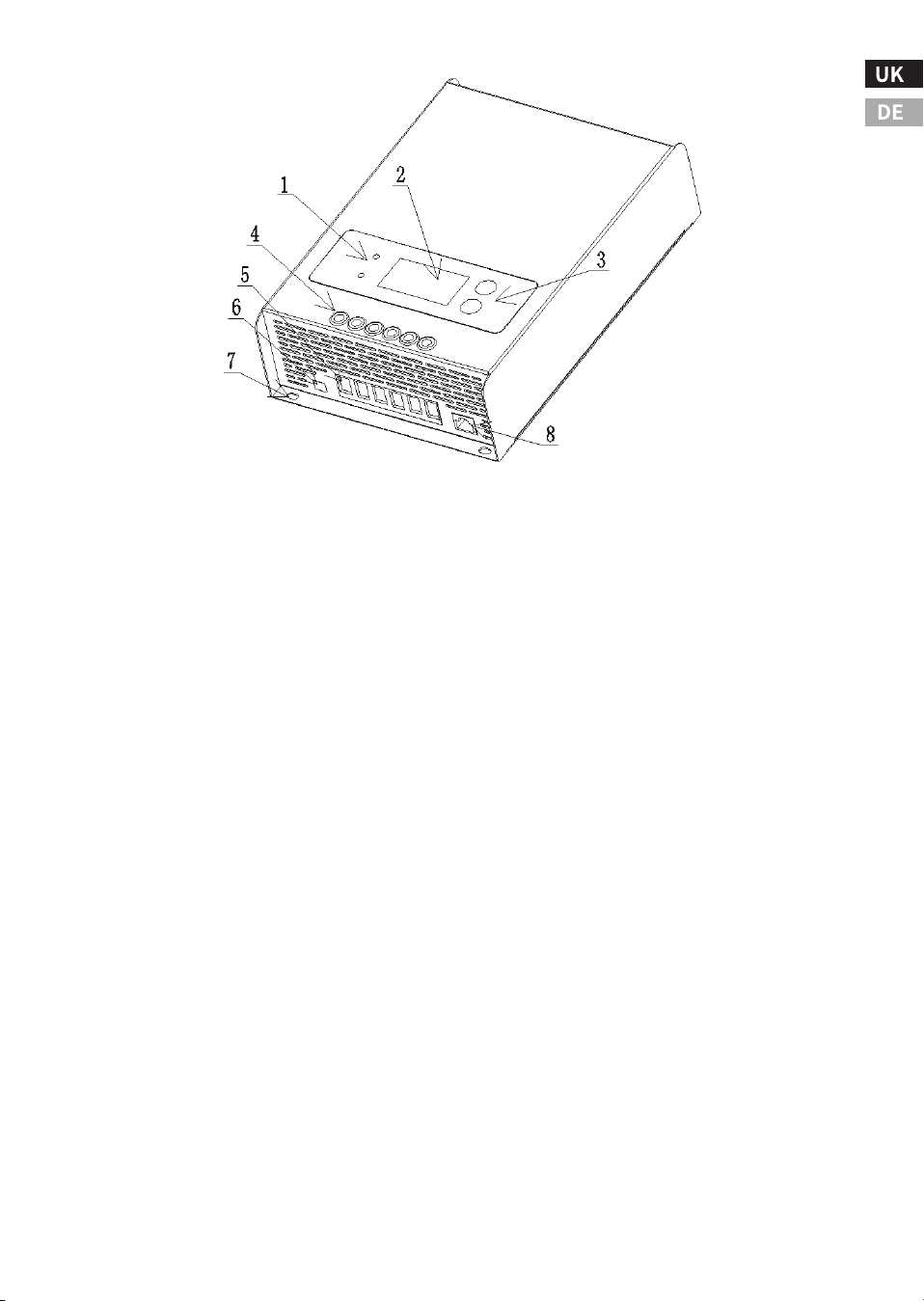
The features and illustration of the controller are as follows:
Ⅱ. Product Overview
-�-

�.� Optional accessories
The following accessories can be purchased separately from autho-
rized dealers:
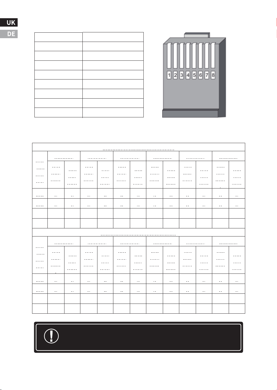
� ‒ Charge status and fault indicators.
� ‒ LCD display.
� ‒ Operation buttons.
� ‒ Holes for wiring screws.
� ‒ Input and output power cable connectors.
(PV+/PV-/BAT+/BAT-/LOAD+/LOAD-).
� ‒ Temperature sensing wire connector.
� ‒ Mounting hole for grounding.
� ‒ RJ�� serial communication interface.
BW-��
It is a wireless communication box that can be used in connection
with the controller. The communication box acts as a transceiver
(near-field remote control), and the user can use the mobile phone
software to monitor the MPPT controller via Bluetooth. The comm
box cannot be used with other external devices.
-�-
�.� Installation Precautions
● Please read through the entire installation section before begin-
ning the installation.
● Be very careful when using batteries. Wear goggles and use fresh
water to wash and clean any contact with battery acid.
● Use insulated tools and avoid placing metal objects near the
battery.
● Do not install in a location prone to water ingress.
● Loose power cord connections and corroded wires can lead to
increased contact resistance or cable impedance, which may result in
melting of wire insulation, burning of surrounding materials, or even
the occurrence of a fire. Ensure that the cables are securely connect-
ed and secured using cable clips to prevent the cables from shaking
during mobile applications.
● This MPPT controller can be connected to a battery or a battery
pack.
● This MPPT controller prevents reverse current leakage at night, so
diodes in series are not required in the system.
● This MPPT controller is only used for solar power generation.
Connection to any other type of power source (such as a wind turbine
or generator) may void the warranty.
Ⅲ. Installation Instructions
-�-
Do not install the MPPT in an enclosure with an open/
flooded battery. Battery fumes are flammable and can
corrode and destroy MPPT circuits.
WARNING
Note: When installing the MPPT in the enclosure,
ensure adequate ventilation. Installation in a sealed
enclosure can result in overheating, reduced power
operation, and shortened product's lifespan.
Serial solar and battery fuses or DC circuit breakers are
required in the system. These guards are located
outside the MPPT controller.
WARNING
�.� Installation Steps
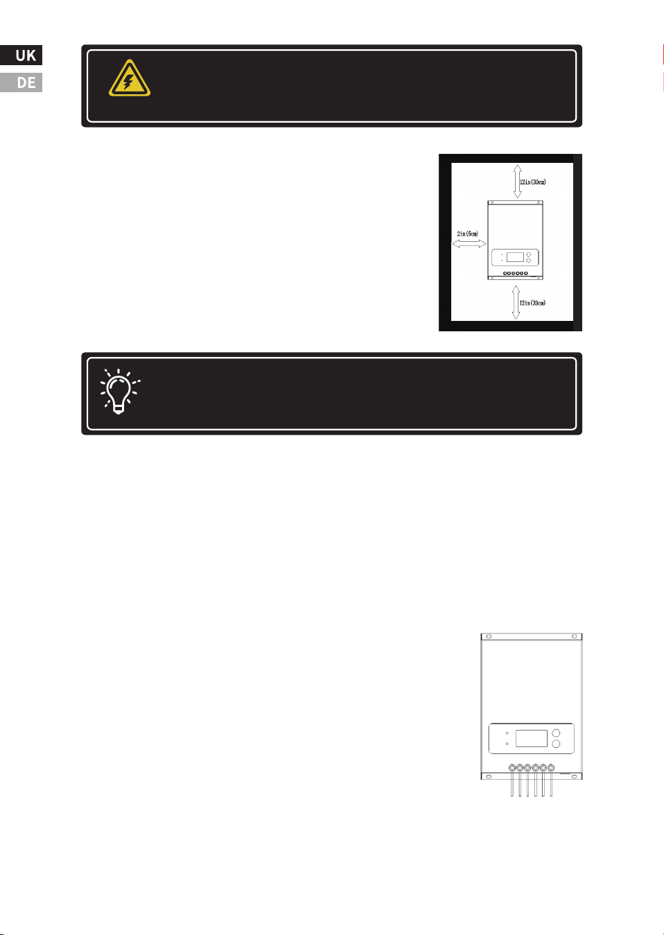
Check the controller for shipping damage. Do
not install directly on flammable surfaces as
the radiator may become hot under certain
operating conditions.
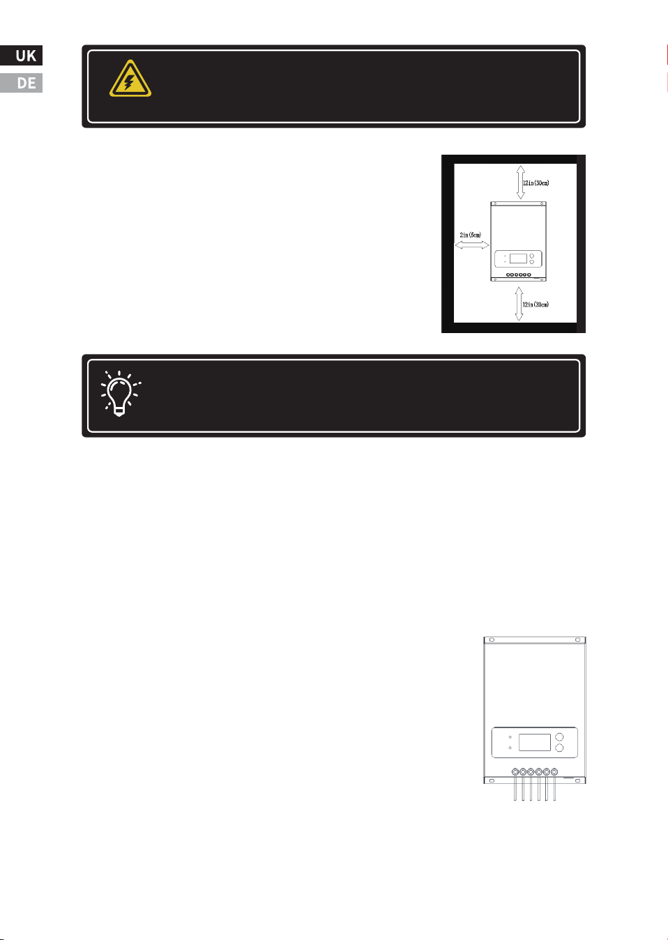
To ensure room for airflow, allow at least �� cm
(�� in) above and below the controller and ��
mm (� in) on both sides. Do not install in a
container where accumulator gas may accumu-
late.
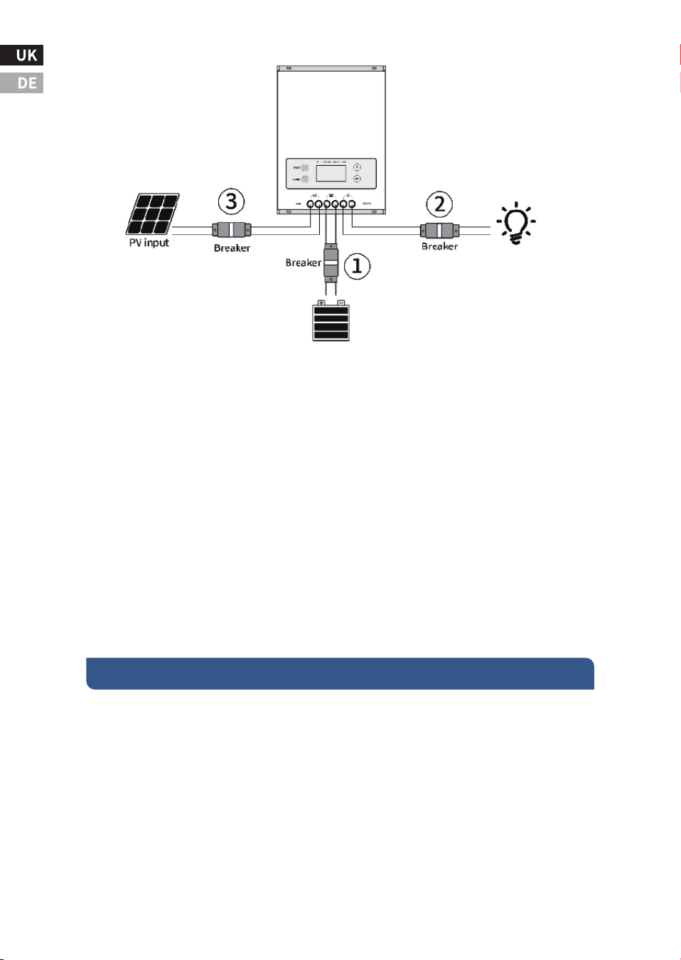
Step �: Connect the input and output power cables.
Follow the wiring sequence ➀, ➁, ➂ to wire and tight-
en the screws.
Step �: Make mounting holes in the mounting wall.
Measure and mark the distance on the wall, drill �
holes of �mm diameter and fill the � holes with plastic
expansion tubes.
Note: There should be enough space between the top and
bottom for the fan to dissipate heat.
Step �: Check Controller Parameter Limits
Ensure that the maximum temperature-compensated open-circuit
voltage (Voc) of the solar array and the load current do not surpass
the specifications for the MPPT version being installed. Multiple
controllers can be installed in parallel on the same battery pack for
greater total charge current. In this type of system, each MPPT must
have its own solar panel. The load terminals of multiple controllers
can be connected together only if the total load does not exceed the
rated current of a single controller.
-�-
Installation must comply with electrical code require-
ments. Select suitable specifications for circuit break-
ers and fuses based on application requirements.
WARNING
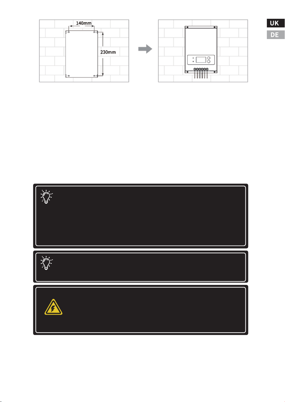
Step �: Mount the Controller to the Wall
Align the fixing holes of the controller with the mounting holes made
in step �, use M� self-tapping screws to fix the controller on the instal-
lation wall and tighten the screws.
Step �: Power on and run
Check to make sure the solar panel and battery are in normal condi-
tion, double check that the input and output cables are connected
correctly, then power up the battery first, then the solar panel, the
controller will run automatically.
-�-
Note: Before connecting the battery, the open circuit
voltage of the battery must be measured . It must exceed ��
volts to activate the controller. If the system voltage is set to
auto-detect, any battery voltage over ��V will be recognized
as a nominal ��V battery, and the device will charge it
accordingly. The ��/��/��V setting is only auto-selected
during the power-up process.
Note: To prevent damage, power must be turned on in the
following order; The power should be turned off in the
reverse order to how it was turned on.
Potential for damage
Disconnect the battery from the MPPT as soon as possi-
ble after the solar input is disconnected. If the battery
is removed during MPPT charging, there is a low
chance of damage to the controller.
WARNING

Start-up steps:
Step �:Turn on the circuit breaker connected to the battery first,
make sure that the controller is connected to the battery (the
controller LCD will display the content), and set the battery type;
Step �:If a DC output is required to control the load,please set the
output control mode first, and then open the DC output "breaker";
Step �:Connect a circuit breaker that turns on the PV input of the
solar panel. If the voltage of the PV input is within the charging oper-
ating range of the controller, the controller will enter the charging
state;
Shut down process:Turn off the "circuit breaker" in turn ➂,➁,➀
�.� The maximum power point tracking technology
Power is equal to the product of voltage and current. The following
equation holds *:
(�)Input Power of MPPT = Output Power of MPPT
(�)Input Voltage × Input Current = Output Voltage × Output Current
Ⅳ. Working principle and operation guide
-�-
* Assuming ���% conversion efficiency, this calculation disregards
cable losses and energy conversion losses. If the Vmp of the solar
panel array is greater than the battery voltage, the battery current
must be proportionally greater than the solar input current to
balance the Input and output power. The greater the difference
between the maximum photovoltaic input voltage and the battery
voltage, the greater the difference between the input and output
currents.
For a given input power, a higher input voltage of a solar module
array results in a lower solar input current. An array of high voltage
solar input modules allows the use of smaller gauge solar wiring. This
is very beneficial for systems that require long wiring between the
solar module array and the MPPT.
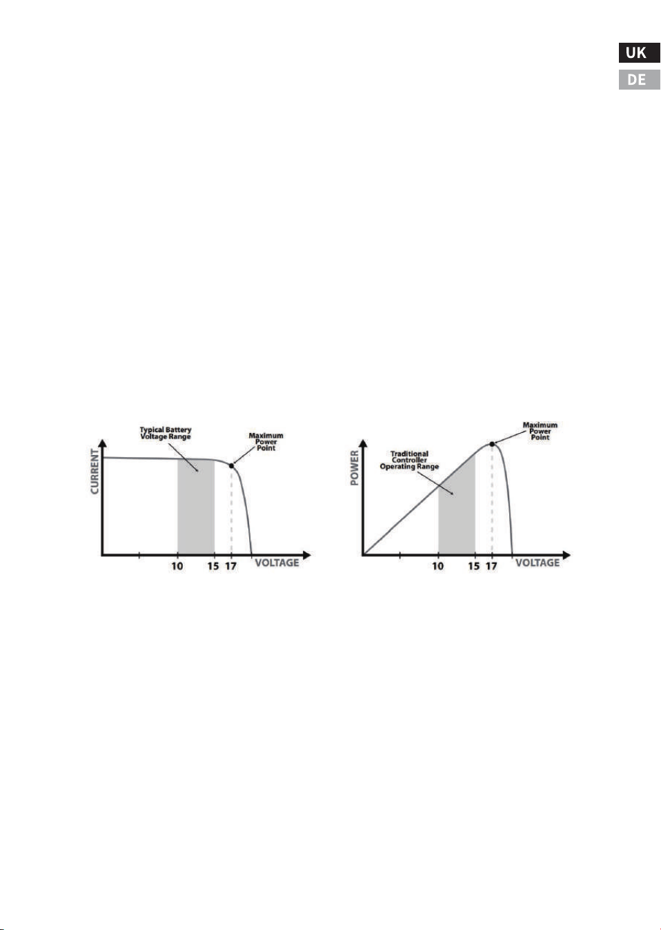
Compared to the traditional controller, the principle of it is to
connect the solar module directly to the battery when charging. This
requires the solar module to operate in a voltage range lower than
the module Vmp. For example, in a ��V system, the battery voltage
may be between ��-��-VDC, but the Vmp of the module is usually
around ��V. The figure below shows a typical current VS voltage
output curve for a nominal ��V charging system.
�.� Charge status and parameters
The controller charges the lead-acid battery
The MPPT controller has a �-stage battery charging algorithm for fast,
efficient and safe charging of lead-acid batteries.
�.CC State (Constant Current Charging): Fast Charging Phase - FAST
�.CV State (constant voltage charging): regulated charging phase -
KEEP
�.CF Status (Float Charging):It prevents the battery from being over-
charged for a long time, and makes up for the loss of self-discharge.
-FULL
�.Boost charging: It activates battery chemistry, desulphurization
effect.
-��-
��V Module Current VS Voltage ��V Module Output Power
BW-��
It is a wireless communication box that can be used in connection
with the controller. The communication box acts as a transceiver
(near-field remote control), and the user can use the mobile phone
software to monitor the MPPT controller via Bluetooth. The comm
box cannot be used with other external devices.
The controller charges the lithium-ion battery
The MPPT controller will charge according to the specifications of the
lithium-ion battery, mainly in two stages. In the first stage, when the
battery voltage is lower than the saturation voltage, it will rapidly
charge according to the maximum power point that is tracked; in the
second stage, when the battery voltage is equal to the saturation
voltage, it will charge at a constant voltage, and the charging current
will gradually decrease to �.
Charging parameter settings
The charging parameters of commonly used lead-acid battery are as
follow. All voltage settings listed are for standard �� volt batteries.
(Example: For a �� volt battery, multiply the voltage setting by �.)
The charging parameters of commonly used lithium-ion batteries:
-��-
��.�V ��.�V ��.�V
��.�V
��.�V
��.�V ��.�V ��.�V
��.�V
��.�V
��..�V
��.�V
��.�V
��.�V
��.�V
Battery Type
Gel (GEL)
Sealed (SEL)
Flooded (FLD)
Custom(CUS)
�� points
user-defined
�� points
user-defined
�� points
user-defined
�� points
User-
defined
Equalization
voltage
Float
charge
Brown-
out
recovery
Constant
charging
Voltage
User-
defined
User-
defined
User-
defined
User-
defined
User-
defined
Equalization
charging
time
Undervolt-
age
protection
Battery Type
LiFePO� ��V(� strings of
lithium iron phosphate )
LiFePO� ��V(� strings of
lithium iron phosphate )
LiFePO� ��V(�� strings of
lithium iron phosphate )
User-defined
Standard
voltage
Saturation
voltage
Discharge-
cut-off
voltage
Cut-off
recovery
voltage
User-defined User-defined User-defined User-defined
��.�V
��.�V
��.�V
��.�V
��.�V
��.�V
��.�V
��.�V
��.�V
��V
��V
��V
�.� Load Control
The main purpose of the load control function is to disconnect the
system load when the battery is discharged to a low voltage state and
reconnect the system load when the battery is charged back to a
certain level. System loads can be lamps, DC appliances, or other
electronic equipment. The total current of all loads must not exceed
the MPPT maximum load rating.
Brief description of load control:
Do not connect multiple MPPT load outputs in parallel to supply DC
loads exceeding ��A of current, unless specified by the MPPT model
in use.
Be careful when connecting loads with specific polarities to control-
ler load terminals. Reverse polarity connections may damage the
load. Be sure to check the load connection carefully before powering
on.
The load output voltage of the controller is the same as that of the
battery string. For example, when the battery voltage is ��.�V, the
load output voltage is also ��.�V.
When the load output current is lower than the rated load current, the
system provides stable power to the load.
When the load output current exceeds the preset load current and
lasts for �minutes in the range of ���% to ���%, the load output is
shut down and switches to the normal off mode.
When the load output current is detected to exceed ���% of the rated
load current, the load output will be shut down immediately and
switch to the normal off mode.
-��-
Note: Risk of Equipment Damage
Do not connect any AC inverter to the load terminals of
the MPPT. The load control circuit may be damaged. The
inverter should be connected to the battery. If any other
load may sometimes exceed the maximum voltage or
current limit, the device should be connected directly to
the battery or battery pack.
Note: These settings are general guidelines for user
operation. MPPT can be set to meet various charging
parameters. Check with the battery manufacturer for
the best battery charging settings.
Attention: Only the Normal ON/OFF mode can be set on the
controller panel. Other modes need to be set through other
optional accessories.
Attention: Please refer to Section �.� for setting the Normally
ON/OFF mode.
Load Control Mode:
�.Normal On/ Off mode: The load output state is on or off.
�.Optical control mode: The load output is turned on or off according
to whether the light is on (Input voltage limit). Please refer to the
following diagram for the working mechanism.
�.Dual-period timing control mode: The load switch of two different
periods is controlled according to two timers. Please refer to the
following diagram for the working mechanism.
�.Fixed time light control mode: According to whether the light is on
(input voltage limit), the load output is controlled to turn on or off in
hourly units.
�.� LED Indicators
Green: Indicates charging status. When the indicator flashes fast, it
means it is in fast charging state (CC mode); when the light flashes
slowly, it means it is in constant voltage charging state (constant
voltage charging CV); when it is always on, it means it is in floating
charging state (CF) or standby mode.
Red: If a fault occurs, the indicator is steady on. If it is off, it indicates
that the device is running normally without faults.
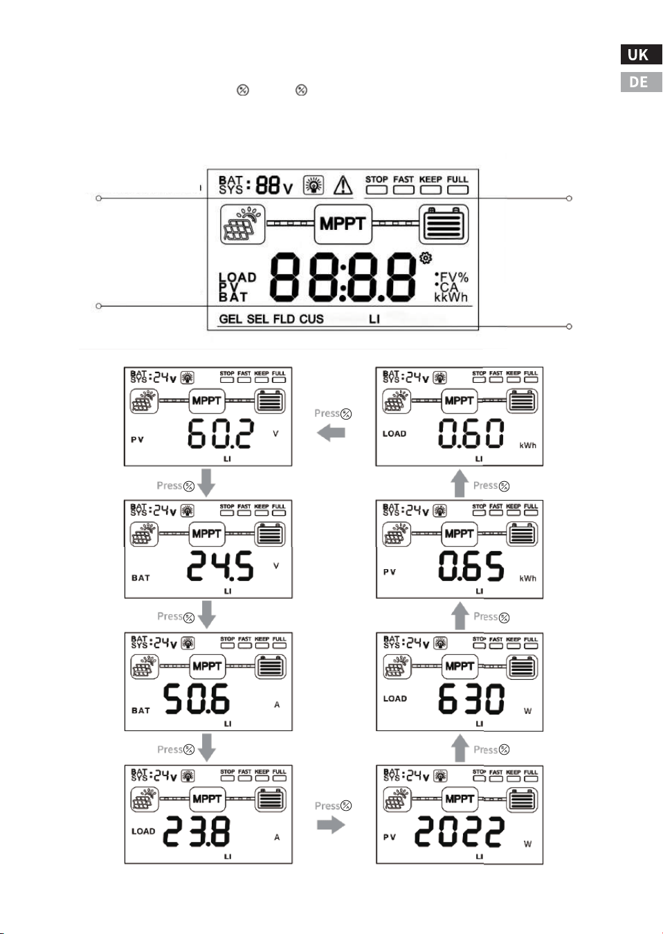
�.� Display and key operation
The default screen backlight duration is �� seconds (the time can be
set on other devices ), and the backlight display can be awakened by
pressing a key or touching the device.
-��-
Attention: When the Load switches to normal off mode,
in order to restart the Load, the user needs to reset the
Load to "on" mode on the controller or reset the Load
mode through the mobile APP, upper computer, and
meter header.
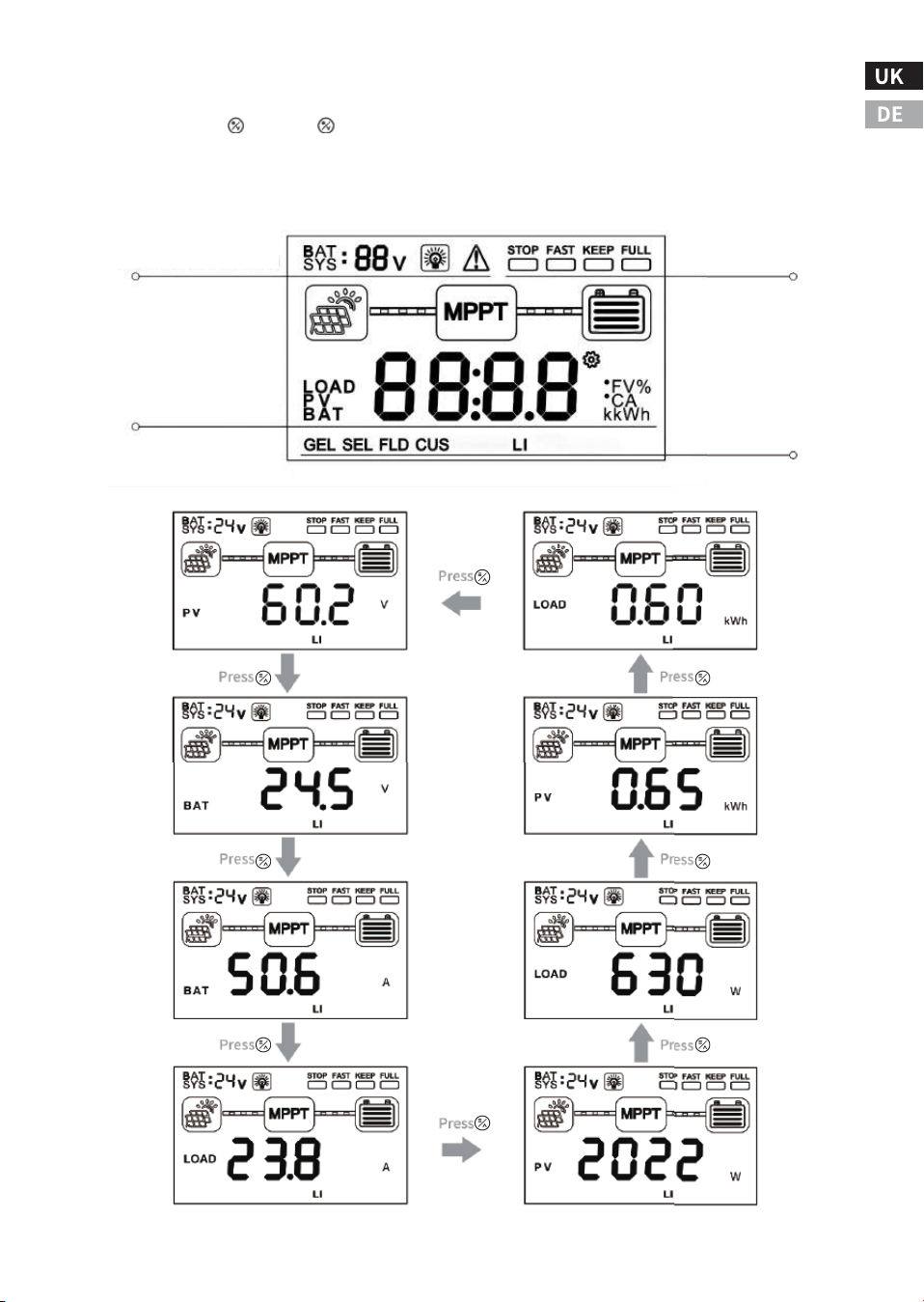
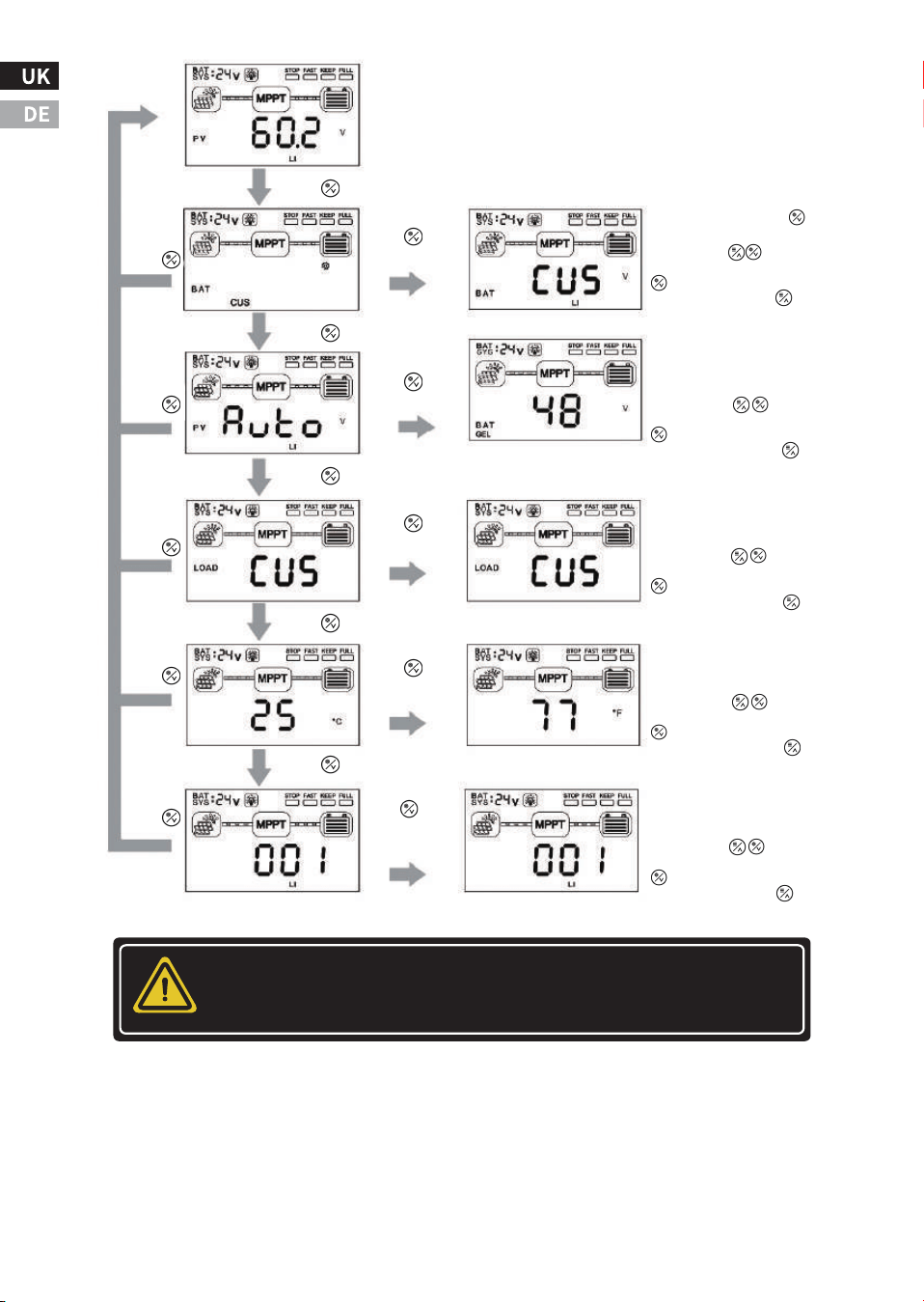
�.� Key operation
Press the " " and " " keys at the same time for � seconds to restore
the factory settings. The specific operation and display logic are
shown in the following figure.
-��-
Battery system, Load and
Alarm status indication
Charging status
indication
Battery type display
Real-time data display

Attention: If you need to customize other parameters, you can do
so through optional attachments.
-��-
Press
Press and hold
the button
for � seconds
Press and hold the
button for �S.
Press the keys to select
the parameter, long press the
key �S to save the settings,
and long press the key for �S
to exit editing.
Battery voltage system setting
interface: ��/��/��/��VNon-
lithium batteries can be set under
the same battery/AUTO.
Load status setting interface:
It can be set to ON,OFF,CUS (user-
defined: through the host machine
or APP settings).
Press
Press
Press
Press
It is invalid if you long press it in lithium
battery mode.
Press
Press
Press
Press
Press
Press and hold
the button
for � seconds
Press and hold
the button
for � seconds
Press and hold
the button
for � seconds
Press and hold
the button
for � seconds
Press the keys to select
the parameter, long press the
key �S to save the settings,
and long press the key for �S
to exit editing.
Press the keys to select
the parameter, long press the
key �S to save the settings,
and long press the key for �S
to exit editing.
Temperature display setting interface:
It can be set to different display
modes of Fahrenheit/Celsius.
Press the keys to select
the parameter, long press the
key �S to save the settings,
and long press the key for �S
to exit editing.
Communication address and
settingnd interface:���~���
address bitscan be set.
Press the keys to select
the parameter, long press the
key �S to save the settings,
and long press the key for �S
to exit editing.
Ⅴ. Common faults and handling
Fault�:
The LCD screen doesn't light up, and the controller doesn't seem to be
powered on.
Solution:
Use a multi-meter to check the voltage of the battery terminals on the
MPPT. The battery voltage must be ��V or higher. If the voltage on the
controller battery terminal is between ��V and ��V and no indicator
light is on, contact the authorized distributor for repair. If the voltage
is not measured, check the wiring, fuses, and circuit breakers.
Fault�:
The controller is not charging.
Solution:
Check fuses, circuit breakers, and wiring connections in power wiring.
Using a multi-meter to check the array voltage directly on the MPPT
solar input terminals. Before starting charging, the input voltage must
be greater than the battery voltage. Check whether the battery voltage
displayed on the LCD screen is within the appropriate range of the
controller system.
-��-
WARNING: Danger of electric shock
Inputs and outputs are not electrically isolated and
may be energized with dangerous solar voltages.
Under certain fault conditions, the battery may over-
charge. Before making contact, test the impedance
between all terminals and ground.
Warning: Danger of electric shock
A means of disconnecting all power electrodes must be
provided. These disconnections must be included in
the fixed wiring. Disconnect all power supplies before
removing the controller wiring cover or repairing the
wiring.

Fault�:
The battery has been in a low or dead state for a long time.
Solution:
Possible reasons:
�.There are too few solar panels to generate enough energy to meet
the system use, and the solar panel array can be increased appropri-
ately.
�. The battery capacity is too small to store enough energy for the
system to use, and the capacity of the battery pack can be appropriate-
ly increased.
-��-

-��-
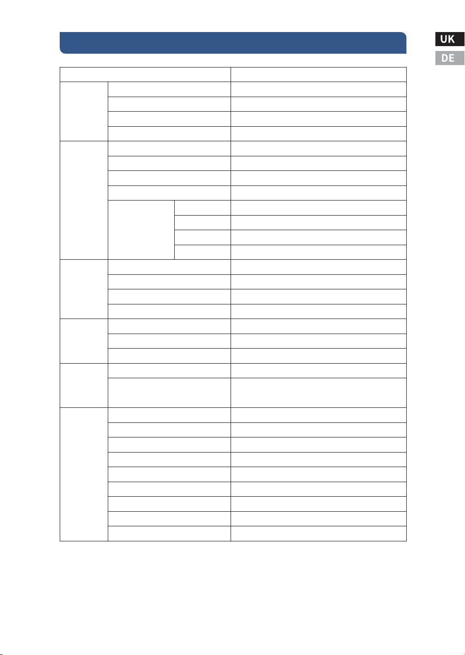
Ⅵ. Specification
ECOMPPT��A
≥��.�%
�.�W~�.�W
Auto
Fan cooling
���Vdc
�V higher than battery voltage
�V higher than the current battery voltage
���Vdc
���W
����W
����W
����W
Lead-acid battery / LiFePO� battery
Optional
��A
Same battery voltage
��A
High-definition LCD segment code backlight display
-��℃~+��℃
-��℃~+��℃
IP��
��mm²
�.��
�.�
���*���*��
���*���*��
Lead-acid battery: fast charge, equal charge, floating
charge; lithium battery: fast charge, equal charge
Normal ON/OFF mode/dual period control mode/
light control mode/light control-fixed time control mode
Input and output over-voltage protection, anti-reverse
connection protection, battery drop protection, etc.
�-pin RJ�� interface/RS���/support host computer monitoring/
support external Bluetooth, WIFI module expansion to realize
app cloud monitoring/support external monitoring header
MPPT efficiency
No-load static loss
System voltage
Cooling method
PV Maximum Open Circuit Voltage (VOC)
Turn on the charging voltage point
Input low voltage protection point
Input overvoltage protection point
Applicable battery type
Lithium battery activation function
Rated charge current
Charging method
Load voltage
Rated load current
Load control method
Display method
Communication method
Protective function
Operating temperature
Storage temperature
IP protection class
Maximum wire size
Net weight (kg)
Gross weight (kg)
Product size (mm)
Packaging size (mm)
��V System
��V System
��V System
��V System
Rated Input
power
Product
Category
Input
Characteristics
Charging
Characteristics
Load
Characteristics
Display/Commu
nication
Other
properties

Protective function
Anti-reverse connection protection battery end and photovoltaic
array end
Photovoltaic array short circuit
Internal overtemperature - Reduced power operation
Load short circuit protection
Load overcurrent protection
Heat sink temperature limit
Overvoltage and undervoltage protection
Battery drop protection
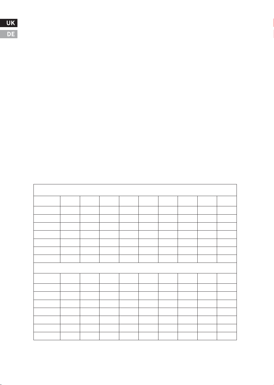
Cable Specification Table
-��-
�% Voltage Drop Charts for ��°C standard Copper Wire
Maximum-� way wire distance for �� Volt systems, standard copper, and �% voltage drop
�-Way Wire Distance (feet), �� Volt System
Wire Size
(AWG)
��A
��A
��A
��A
��A
��A
��A
��A
��A
�/�*
��.�
��.�
��.�
��.�
��.�
��.�
��.�
��.�
��.�
�/�*
��.�
��.�
��.�
��.�
��.�
��.�
��.�
��.�
��.�
�
��.�
��.�
��.�
��.�
��.�
��.�
��.�
��.�
��.�
�
�.�
�.�
�.�
�.�
��.�
��.�
��.�
��.�
��.�
�
�.�
�.�
�.�
�.�
�.�
�.�
�.�
��.�
��.�
�
�.�
�.�
�.�
�.�
�.�
�.�
�.�
�.�
�.�
��
�.�
�.�
�.�
�.�
�.�
�.�
�.�
�.�
�.�
�-Way Wire Distance (meters), �� Volt System
Wire Size
(mm
�
)
��A
��A
��A
��A
��A
��A
��A
��A
��A
��*
�.�
�.�
�.�
�.�
��.�
��.�
��.�
��.�
��.�
��*
�.�
�.�
�.�
�.�
�.�
�.�
��.�
��.�
��.�
��*
�.�
�.�
�.�
�.�
�.�
�.�
�.�
�.�
��.�
��
�.�
�.�
�.�
�.�
�.�
�.�
�.�
�.�
�.�
��
�.�
�.�
�.�
�.�
�.�
�.�
�.�
�.�
�.�
��
�.�
�.�
�.�
�.�
�.�
�.�
�.�
�.�
�.�
�
�.�
�.�
�.�
�.�
�.�
�.�
�.�
�.�
�.�
-��-
Attention: *Wires larger than � AWG (�� mm²) must be
terminated at the combiner box outside the MPPT. Use �
AWG (�� mm²) or smaller wire to connect the MPPT to the
combiner box.
Attention: *The specified wire lengths are for a pair of
wires (one-way distance) from the solar or battery power
source to the controller.
Maximum-� way wire distance for �� Volt systems, solid copper,and �% voltage drop
�% Voltage Drop Charts for ��°C Solid Copper Wire
�-Way Wire Distance (feet), �� Volt System
Wire Size
(AWG)
��A
��A
��A
��A
��A
��A
��A
��A
��A
�/�*
��.�
��.�
��.�
��.�
��.�
��.�
��.�
��.�
��.�
�/�*
��.�
��.�
��.�
��.�
��.�
��.�
��.�
��.�
��.�
�
��.�
��.�
��.�
��.�
��.�
��.�
��.�
��.�
��.�
�
�.�
�.�
��.�
��.�
��.�
��.�
��.�
��.�
��.�
�
�.�
�.�
�.�
�.�
�.�
�.�
��.�
��.�
��.�
�
�.�
�.�
�.�
�.�
�.�
�.�
�.�
�.�
��.�
��
�.�
�.�
�.�
�.�
�.�
�.�
�.�
�.�
�.�
�-Way Wire Distance (meters),�� Volt System
Wire Size
(mm )
��A
��A
��A
��A
��A
��A
��A
��A
��A
��*
�.�
�.�
��.�
��.�
��.�
��.�
��.�
��.�
��.�
��*
�.�
�.�
�.�
�.�
��.�
��.�
��.�
��.�
��.�
��*
�.�
�.�
�.�
�.�
�.�
�.�
�.�
��.�
��.�
��
�.�
�.�
�.�
�.�
�.�
�.�
�.�
�.�
�.�
��
�.�
�.�
�.�
�.�
�.�
�.�
�.�
�.�
�.�
��
�.�
�.�
�.�
�.�
�.�
�.�
�.�
�.�
�.�
�
�.�
�.�
�.�
�.�
�.�
�.�
�.�
�.�
�.�
�
Attention: N in the table represents the number of series, and the
data is for reference only.
RJ�� Port definitions
-��-
Pin
Function
�
RS���-A
�
RS���-B
�
-
�
-
�
GND
�
GND
�
+�V
�
+�V
Number of PV modules in series reference table
Voc * N = PV input < ���dc
Syst
em
Volt
age
Voc<��V
Voc<��V
Voc<��V
Voc<��V
Voc<��V
Voc<��V
The
maxi
mum
The
opti
mum
The
maxi
mum
The
opti
mum
The
maxi
mum
The
opti
mum
The
maxi
mum
The
opti
mum
The
maxi
mum
The
opti
mum
The
maxi
mum
.
The
opti
mum
��V
�
�
�
�
�
�
�
�
�
�
�
�
��V
�
�
�
�
�
�
�
�
�
�
�
�
��V
�
�
�
�
�
�
�
�
�
�
�
�
��V
�
�
�
�
�
�
�
�
�
�
�
�
Voc * N = PV input < ���Vdc
Syst
em
Volt
age
Voc<��V
Voc<��V
Voc<��V
Voc<��V
Voc<��V
Voc<��V
The
maxi
mum
.
The
opti
mum
The
maxi
mum
The
opti
mum
The
maxi
mum
The
opti
mum
The
maxi
mum
The
opti
mum
The
maxi
mum
The
opti
mum
The
maxi
mum
The
opti
mum
��V
�
�
�
�
�
�
�
�
�
�
�
�
��V
�
�
�
�
�
�
�
�
�
�
�
�
��V
�
�
�
�
�
�
�
�
�
�
�
�
��V
�
�
�
�
�
�
�
�
�
�
�
�
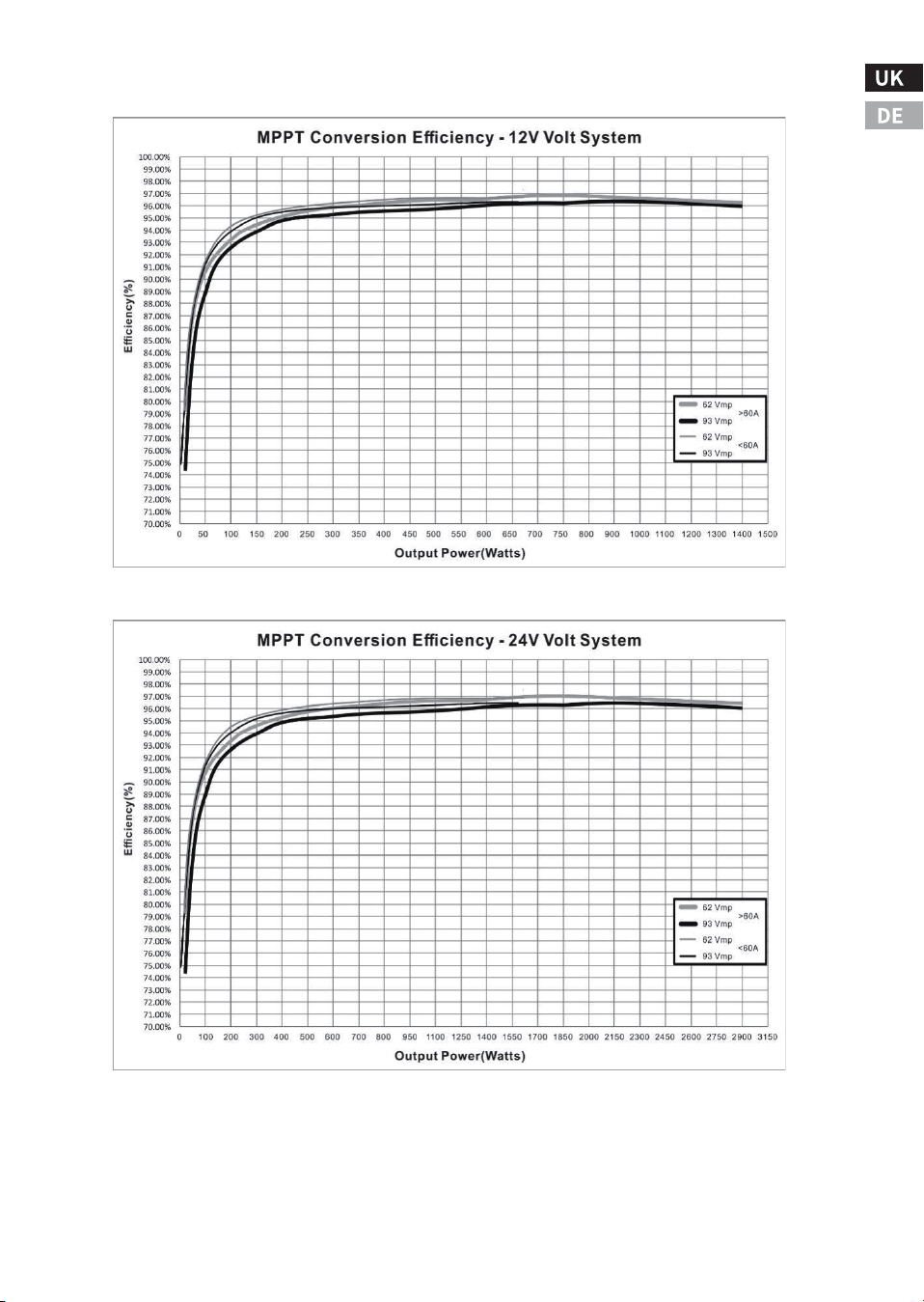
Efficiency chart
-��-

-��-
-��-
ⅥI. Technical Support
�.Renoly Support
Address(US): ���� East State Hwy D Suite C Springfield,
Missouri �����
Address(DE): ECO-Worthy Europe GmbH Otto-Hahn-Str. ��
����� Friedrichsdorf - Köppern Germany
Youtube: @ecoworthy
Facebook: https://www.facebook.com/ecoworthy.store/
Tiktok: https://www.tiktok.com/@eco_worthy
�) Customer service telephone numbers:
�) Company address: USA/Germany
�) Customer service email:
Tel(DE): +�� ����-����-���
Tel(US/CA): �-���-���-����
Tel(UK): +�� ���� ������
E-mail:customer. service@eco-worthy.com
�) Official website address:
Web: https://www.eco-worthy.com/
�) Official social media:
Customer Service Hours:
Mon-Fri �:�� AM - �:�� PM (CST)US:
Mon-Fri � AM - � PM(GMT)UK:
Mon-Fri � AM - � PM(CET)DE:
If you cannot get through by phone, please send us an email.
Note:
ECO-WORTHY
��V/��V/��V/��V
��A MPPT
MANUAL
Installations- und Betriebshandbuch
Controller
Version: �.�
UNTERSTÜTZUNG
Wenn Sie technische Probleme haben und keine Lösung
in diesem Handbuch finden, wenden Sie sich bitte an
ECO-WORTHY, um weitere Unterstützung zu erhalten.
·Web://www.eco-worthy.com/
·E-mail: customer.service@eco-worthy.com
PV
BAT
LOAD
ERROR
·Call:+� ��� ��� ����(US/CA)
+�� ���� ������(UK)
+�� ���� ���� ���(DE)

Inhalt
Ⅰ. Wichtige Sicherheitshinweise
Ⅱ. Produktübersicht
Ⅲ. Einbauanleitung
Ⅳ. Arbeitsprinzip und Betriebsanleitung
Ⅴ. Häufige Fehler und Handhabung
Ⅵ. Spezifikation
VII. Technische Unterstützung
�.� Symbole für Schlüsselindikatoren
�.� Sicherheitshinweise
�.� Sicherheitsvorkehrungen bei der Installation
�.� Sicherheit der Batterie
�.� Produktmerkmale
�.� Optionales Zubehör
�.� Vorsichtsmaßnahmen bei der Installation
�.� Montageschritte
�.� Die Technologie zur Nachführung des maximalen Leistungspunktes
�.� Ladestatus und Parameter
�.� Laststeuerung
�.� LED-Anzeigen
�.� Display und Tastenbedienung
�.� Tastenbedienung
............................................................�
.................................................................�
........................................................................................�
............................................�
..................................................................................�
.......................................................................................�
........................................................................................�
.......................................................................................�
.........................................................................................�
..................................................�
..................................................................................................�
.....................................��
...��
.........................................................................��
.................................................................................................��
...................................................................................................��
.....................................................................��
............................................................................................��
..................................................��
...............................................................................................��
.............................................................��
Es wird empfohlen, diese Anleitung aufzubewahren, da sie wichtige
Sicherheits-, Installations- und Betriebsanweisungen für den
MPPT-Solarregler enthält.
�.� Wichtige Anzeigesymbole
Die folgenden Symbole werden in diesem Handbuch verwendet, um
auf potenziell gefährliche Bedingungen oder wichtige Sicherheitshin-
weise hinzuweisen:
�.� Sicherheitshinweise
● Lesen Sie vor der Installation alle Anweisungen und
Vorsichtsmaßnahmen in diesem Handbuch.
● Der MPPT enthält keine vom Benutzer reparierbaren Teile.
Versuchen Sie nicht, das Steuergerät zu zerlegen oder zu reparieren.
Ⅰ. Wichtige Sicherheitshinweise
-�-
Weist auf die Gefahr eines Stromschlags hin. Wenn dies nicht
vermieden wird, kann es zu Todesfällen kommen.
Weist auf einen potenziell gefährlichen Zustand hin, der zu
Verletzungen oder zum Tod führen kann.
Weist auf wichtige Informationen oder Warnungen im Zusammen-
hang mit den im Text behandelten Konzepten hin.
Weist darauf hin, dass weitere Informationen in anderen Dokumenten
zu dem Thema und dem Leser verfügbar sind.
Weist auf wichtige Schritte oder Tipps für eine optimale Leistung
hin.
Symbole
Definition
WARNUNG HEISSE OBERFLÄCHE: Weist auf die Gefahr hoher Tempera-
turen hin, die, wenn sie nicht vermieden werden, zu Verbrühungen
führen können.
-�-
● Erfordert die Trennung von externer Solarenergie und Batterie.
Trennen Sie die Stromversorgung vom Regler, bevor Sie den MPPT
installieren oder einstellen.
�.� Sicherheitsvorkehrungen bei der Installation
● Installieren Sie den MPPT in Innenräumen. Halten Sie die Hände
von den Komponenten fern und stellen Sie sicher, dass kein Wasser
in das Steuergerät eindringt.
● Montieren Sie den MPPT an einem Ort, der außer Reichweite ist,
um versehentlichen Kontakt zu vermeiden. Die Kühlkörper des MPPT
können während des Betriebs sehr heiß werden.
● Wenn Sie Batterien verwenden, benutzen Sie bitte isolierte
Werkzeuge.
● Vermeiden Sie das Tragen von Schmuck während der Installation.
● Der Batteriesatz muss aus Batterien desselben Typs, derselben
Marke und desselben Alters bestehen.
● Rauchen Sie nicht in der Nähe des Batteriesatzes.
● Die Stromanschlüsse müssen fest angezogen sein, um eine Über-
hitzung durch lose Verbindungen zu vermeiden.
● Verwenden Sie ausreichend dimensionierte Kabel und
Schutzschalter.
● Die Erdung kann an den unteren Befestigungslöchern des Gehäus-
es vorgenommen werden.
● Der MPPT-Regler muss von einem qualifizierten Techniker in
Übereinstimmung mit den elektrischen Vorschriften des Landes
installiert werden.
Gefahr eines Stromschlags. Keine Leistungs- oder andere
Klemmen sind galvanisch vom DC-Eingang getrennt und
können mit gefährlichen Solarspannungen versorgt werden.
Bei bestimmten Fehlfunktionen kann die Batterie überladen
werden. Prüfen Sie vor der Kontaktaufnahme die Impedanz
zwischen allen Klemmen und der Erde.
WARNING
Der Kommunikationsanschluss des Steuergeräts ist keine
isolierte Quelle oder ein isoliertes Signal. Bitte seien Sie
vorsichtig, wenn Sie eine Verbindung mit anderen
Geräten herstellen.
WARNING
The controller does not have a GFDI (Ground Fault Detection
Device).
WARNING
● Es sollte ein Mechanismus zur Abschaltung aller Stromelektroden
eingebaut werden. Stellen Sie sicher, dass diese Trennvorrichtungen
Teil des permanenten Verkabelungssystems sind.
● Der positive Stromanschluss des MPPT sollte in einer gemeins-
amen positiven Konfiguration angeschlossen werden. Falls erforder-
lich, erden Sie das System gemäß den mitgelieferten Anweisungen,
örtlichen Vorschriften und Bestimmungen.
● Der Erdungspunkt des MPPT-Gehäuses muss sicher mit einem
zuverlässigen Erdungskabel verbunden sein.
● Der Erdungsleiter sollte fest gesichert sein, um ein versehentliches
Trennen zu verhindern.
�.� Sicherheit der Batterie
● Batteriereparaturen sollten von Personen durchgeführt oder
beaufsichtigt werden, die sich mit Batterien und den erforderlichen
Sicherheitsmaßnahmen auskennen.
● Seien Sie beim Umgang mit großen Blei-Säure-Batterien sehr
vorsichtig. Tragen Sie eine Schutzbrille und halten Sie frisches
Wasser bereit, um den Kontakt mit der Batteriesäure zu vermeiden.
● Legen Sie Uhren, Ringe, Schmuck und andere Metallgegenstände
ab, bevor Sie die Batterie benutzen.
● Tragen Sie Gummihandschuhe und Gummistiefel.
● Verwenden Sie Werkzeuge mit isolierten Griffen und vermeiden
Sie es, Werkzeuge oder Metallgegenstände auf die Batterie zu legen.
-�-
Bei Batterien besteht die Gefahr eines elektrischen Schlags oder einer
Verbrennung aufgrund eines hohen Kurzschlussstroms, eines Brands
oder einer Explosion der Abgase. Bitte beachten Sie die entsprechenden
Vorsichtsmaßnahmen.
WARNING
Es besteht Explosionsgefahr. Batterien müssen ordnungsgemäß
entsorgt werden. Entsorgen Sie die Batterien nicht in einem Feuer.
Beachten Sie die örtlichen Vorschriften und Bestimmungen.
WARNING
Hinweis: Verwenden Sie beim Auswechseln der Batterien die richtige
Anzahl, Größe, Art und Leistung entsprechend der Anwendung und
dem Systemdesign.
Hinweis: Öffnen oder beschädigen Sie die Batterie nicht. Die freige-
setzten Elektrolyte sind schädlich für die Haut und können giftig sein.

● Trennen Sie das Solarmodul oder eine andere Ladestromquelle,
bevor Sie die Batteriepole anschließen oder abklemmen.
● Prüfen Sie, ob die Batterie versehentlich geerdet worden ist. Um
das Risiko eines solchen Schocks zu verringern, stellen Sie sicher,
dass die Batterie während der Installation und Wartung nicht geerdet
ist, insbesondere bei Geräten ohne geerdeten Stromkreis oder im
Falle von Fernbatteriesystemen.
● Lesen Sie die Anweisungen des Batterieherstellers sorgfältig
durch, bevor Sie den MPPT installieren/anschließen oder die Batterie
aus dem MPPT entfernen.
● Vermeiden Sie einen Kurzschluss mit den an der Batterie anges-
chlossenen Kabeln.
● Suchen Sie bei einem Unfall Hilfe bei einer Person in der Nähe.
● Während des Ladevorgangs kann explosives Batteriegas entste-
hen. Sorgen Sie für eine ausreichende Belüftung, damit das Gas
entweichen kann.
● Im Bereich der Batterie nicht rauchen.
● Wenn Batteriesäure mit der Haut in Berührung kommt, mit Wasser
und Seife waschen. Wenn die Säure in die Augen gelangt, spülen Sie
sie mit Süßwasser aus und suchen Sie einen Arzt auf.
● Vergewissern Sie sich vor dem Laden der Blei-Säure-Batterie, dass
der Elektrolytstand der Batterie korrekt ist. Versuchen Sie nicht, eine
gefrorene Batterie zu laden.
● Achten Sie beim Auswechseln der Batterie auf das Recycling der
Batterie.
�.� Produktmerkmale
Die Merkmale und die Abbildung des Controllers sind wie folgt:
Ⅱ. Product Overview
-�-
�.� Optionales Zubehör
Das folgende Zubehör kann separat bei autorisierten Händlern
erworben werden:
� - Ladezustands- und Fehleranzeige.
� - LCD-Anzeige.
� - Bedientasten.
� - Löcher für Schrauben zur Verkabelung.
� - Anschlüsse für Eingangs- und Ausgangsstromkabel.
(PV+/PV-/BAT+/BAT-/LOAD+/LOAD-).
� - Anschluss für Temperaturmesskabel.
� - Montageöffnung für die Erdung.
� - Serielle Kommunikationsschnittstelle RJ��.
BW-��
Es handelt sich um eine drahtlose Kommunikationsbox, die in
Verbindung mit dem Regler verwendet werden kann. Die Kommu-
nikationsbox fungiert als Transceiver (Nahfeld-Fernbedienung), und
der Benutzer kann die Mobiltelefon-Software zur Überwachung des
MPPT-Reglers über Bluetooth verwenden. Die Kommunikationsbox
kann nicht mit anderen externen Geräten verwendet werden.
-�-
�.� Vorsichtsmaßnahmen bei der Installation
● Lesen Sie bitte den gesamten Abschnitt über die Installation durch,
bevor Sie mit der Installation beginnen.
● Seien Sie beim Umgang mit Batterien sehr vorsichtig. Tragen Sie
eine Schutzbrille und verwenden Sie frisches Wasser, um jeden
Kontakt mit der Batteriesäure abzuwaschen und zu reinigen.
● Verwenden Sie isolierte Werkzeuge und vermeiden Sie es, Metall-
gegenstände in die Nähe der Batterie zu bringen.
● Installieren Sie das Gerät nicht an einem Ort, an dem Wasser eindrin-
gen kann.
● Lose Netzkabelverbindungen und korrodierte Drähte können zu
einem erhöhten Übergangswiderstand oder einer erhöhten Kabe-
limpedanz führen, was zum Schmelzen der Kabelisolierung, zum
Verbrennen der umgebenden Materialien oder sogar zum Entstehen
eines Brandes führen kann. Stellen Sie sicher, dass die Kabel sicher
angeschlossen und mit Kabelklemmen gesichert sind, um zu verhin-
dern, dass die Kabel bei mobilen Anwendungen wackeln.
● Dieser MPPT-Regler kann an eine Batterie oder ein Batteriepaket
angeschlossen werden.
● Dieser MPPT-Regler verhindert nachts den Verlust von Rückstrom, so
dass Dioden in Serie im System nicht erforderlich sind.
● Dieser MPPT-Regler wird nur für die Solarstromerzeugung verwen-
det. Der Anschluss an eine andere Art von Stromquelle (z. B. eine
Windturbine oder ein Generator) kann zum Erlöschen der Garantie
führen.
Ⅲ. Installation Instructions
-�-
Installieren Sie den MPPT nicht in einem Gehäuse mit
einer offenen/überfluteten Batterie. Batteriedämpfe
sind brennbar und können die MPPT-Schaltkreise korr-
odieren und zerstören.
WARNING
Hinweis: Achten Sie bei der Installation des MPPT im
Gehäuse auf eine ausreichende Belüftung. Die Installation in
einem geschlossenen Gehäuse kann zu Überhitzung, reduz-
ierter Leistung und verkürzter Lebensdauer des Produkts
führen.
Im System sind serielle Solar- und Batteriesicherungen
oder DC-Schutzschalter erforderlich. Diese Schutzvor-
richtungen befinden sich außerhalb des MPPT-Reglers.
WARNING
�.� Montageschritte
Überprüfen Sie den Regler auf Transportschäden.
Installieren Sie das Gerät nicht direkt auf brennbaren
Oberflächen, da der Heizkörper unter bestimmten
Betriebsbedingungen heiß werden kann.
Um einen ausreichenden Luftstrom zu gewährleisten,
sollte oberhalb und unterhalb des Reglers mindestens
�� cm und an beiden Seiten �� mm Platz gelassen
werden. Installieren Sie das Gerät nicht in einem
Behälter, in dem sich Speichergas ansammeln kann.
Schritt �: Schließen Sie die Eingangs- und Ausgangsstromk-
abel an.
Befolgen Sie die Verdrahtungsreihenfolge ➀, ➁, ➂ zum
Verdrahten und ziehen Sie die Schrauben fest.
Schritt �: Befestigungslöcher in der Montagewand anbrin-
gen.
Messen und markieren Sie den Abstand an der Wand,
bohren Sie � Löcher mit einem Durchmesser von � mm und
füllen Sie die � Löcher mit Kunststoff-Dehnungsrohren.
Hinweis: Zwischen der Ober- und Unterseite sollte genügend
Platz sein, damit der Lüfter die Wärme abführen kann.
Schritt �: Überprüfen der Parametergrenzen des Reglers
Vergewissern Sie sich, dass die maximale temperaturkompensierte Leerlauf-
spannung (Voc) des Solargenerators und der Laststrom die Spezifikationen
für die zu installierende MPPT-Version nicht überschreiten. Um einen
höheren Gesamtladestrom zu erzielen, können mehrere Regler parallel an
demselben Batteriesatz installiert werden. Bei dieser Art von System muss
jeder MPPT-Regler über ein eigenes Solarpanel verfügen. Die Lastklemmen
mehrerer Regler können nur dann miteinander verbunden werden, wenn die
Gesamtlast den Nennstrom eines einzelnen Reglers nicht überschreitet.
-�-
Die Installation muss den Anforderungen der Elektrov-
orschriften entsprechen. Wählen Sie geeignete Spezifika-
tionen für Schutzschalter und Sicherungen entsprechend
den Anwendungsanforderungen.
WARNING

Schritt �: Montieren des Controllers an der Wand
Richten Sie die Befestigungslöcher des Controllers auf die in Schritt � vorge-
nommenen Montagebohrungen aus, verwenden Sie M�-Schneidschrauben,
um den Controller an der Installationswand zu befestigen, und ziehen Sie die
Schrauben fest.
Schritt �: Einschalten und Betrieb
Vergewissern Sie sich, dass das Solarpanel und die Batterie in normalem
Zustand sind, überprüfen Sie, ob die Eingangs- und Ausgangskabel richtig
angeschlossen sind, schalten Sie dann zuerst die Batterie und dann das
Solarpanel ein, der Regler läuft automatisch.
-�-
Hinweis: Bevor die Batterie angeschlossen wird, muss die Leerlauf-
spannung der Batterie gemessen werden. Sie muss mehr als ��
Volt betragen, um den Regler zu aktivieren. Wenn die Systemspan-
nung auf automatische Erkennung eingestellt ist, wird jede Batter-
iespannung über �� V als nominale ��-V-Batterie erkannt und das
Gerät lädt sie entsprechend auf. Die Einstellung ��/��/��V wird nur
während des Einschaltvorgangs automatisch ausgewählt.
Hinweis: Um Schäden zu vermeiden, muss das Gerät in der folgen-
den Reihenfolge eingeschaltet werden: Das Ausschalten erfolgt in
umgekehrter Reihenfolge wie das Einschalten.
Mögliche Schäden
Trennen Sie die Batterie so schnell wie möglich vom MPPT,
nachdem der Solareingang abgeschaltet wurde. Wenn die
Batterie während des MPPT-Ladevorgangs entfernt wird,
besteht ein geringes Risiko einer Beschädigung des Reglers.
WARNING
Schritte zur Inbetriebnahme:
Schritt �:Schalten Sie zuerst den mit der Batterie verbundenen
Schutzschalter ein, vergewissern Sie sich, dass der Regler mit der Batterie
verbunden ist (die LCD-Anzeige des Reglers zeigt den Inhalt an), und stellen
Sie den Batterietyp ein;
Schritt �:Wenn ein DC-Ausgang zur Steuerung der Last benötigt wird,
stellen Sie bitte zuerst den Ausgangssteuerungsmodus ein und öffnen Sie
dann den DC-Ausgangsschalter";.
Schritt �:Schließen Sie einen Schutzschalter an, der den PV-Eingang des
Solarmoduls einschaltet. Wenn die Spannung des PV-Eingangs innerhalb des
Ladebetriebsbereichs des Reglers liegt, geht der Regler in den Ladezustand
über;.
�.� Die Technologie des Maximum Power Point Tracking
Die Leistung ist gleich dem Produkt aus Spannung und Strom. Es gilt die
folgende Gleichung *:
(�)Eingangsleistung von MPPT = Ausgangsleistung von MPPT
(�) Eingangsspannung × Eingangsstrom = Ausgangsspannung ×
Ausgangsstrom
Ⅳ. Arbeitsprinzip und Betriebsanleitung
-�-

* Unter der Annahme eines Umwandlungswirkungsgrads von ��� % bleiben
bei dieser Berechnung Kabelverluste und Energieumwandlungsverluste
unberücksichtigt. Wenn die Vmp des Solarmodulfelds größer ist als die
Batteriespannung, muss der Batteriestrom proportional größer sein als der
Solareingangsstrom, um die Eingangs- und Ausgangsleistung auszugleichen.
Je größer die Differenz zwischen der maximalen Photovoltaik-Eingangsspan-
nung und der Batteriespannung ist, desto größer ist auch die Differenz
zwischen dem Eingangs- und dem Ausgangsstrom.
Bei einer gegebenen Eingangsleistung führt eine höhere Eingangsspannung
einer Solarmodulanordnung zu einem niedrigeren Eingangsstrom. Eine
Anordnung von Solarmodulen mit hoher Eingangsspannung ermöglicht die
Verwendung von Solarkabeln mit geringerem Querschnitt. Dies ist sehr
vorteilhaft für Systeme, die eine lange Verkabelung zwischen dem Solarmod-
ulfeld und dem MPPT benötigen.
Im Vergleich zum traditionellen Regler besteht das Prinzip darin, das Solar-
modul beim Laden direkt mit der Batterie zu verbinden. Dies erfordert, dass
das Solarmodul in einem Spannungsbereich arbeitet, der niedriger ist als die
Vmp des Moduls. In einem ��-V-System kann die Batteriespannung beispiels-
weise zwischen �� und �� VDC liegen, aber die Vmp des Moduls beträgt
normalerweise etwa �� V. Die folgende Abbildung zeigt eine typische
Strom-Spannungs-Ausgangskurve für ein nominales ��-V-Ladesystem.
�.� Ladestatus und Parameter
Der Regler lädt die Blei-Säure-Batterie
Der MPPT-Regler verfügt über einen �-stufigen Batterieladealgorithmus für
schnelles, effizientes und sicheres Laden von Blei-Säure-Batterien.
�.CC-Status (Konstantstromladung): Schnell-Ladephase - FAST
�.CV-Status (Laden mit konstanter Spannung): geregelte Ladephase - KEEP
�.CF-Status (Float Charging): Verhindert, dass die Batterie für eine lange Zeit
überladen wird, und gleicht den Verlust der Selbstentladung aus. -VOLL
�.verstärkte Ladung: Es aktiviert die Batteriechemie, Entschwefelungseffekt.
-��-
��V Modulstrom VS Spannung ��V Modul Ausgangsleistung

BW-��
Es handelt sich um eine drahtlose Kommunikationsbox, die in
Verbindung mit dem Regler verwendet werden kann. Die Kommu-
nikationsbox fungiert als Transceiver (Nahfeld-Fernbedienung), und
der Benutzer kann die Mobiltelefon-Software zur Überwachung des
MPPT-Reglers über Bluetooth verwenden. Die Kommunikationsbox
kann nicht mit anderen externen Geräten verwendet werden.
Der Controller lädt die Lithium-Ionen-Batterie
Der MPPT-Controller lädt entsprechend den Spezifikationen der
Lithium-Ionen-Batterie, hauptsächlich in zwei Stufen. In der ersten Stufe,
wenn die Batteriespannung niedriger als die Sättigungsspannung ist, lädt er
schnell entsprechend dem verfolgten Punkt maximaler Leistung; in der
zweiten Stufe, wenn die Batteriespannung gleich der Sättigungsspannung
ist, lädt er mit einer konstanten Spannung, und der Ladestrom sinkt allmäh-
lich auf �.
Einstellungen der Ladeparameter
Die Ladeparameter für gängige Blei-Säure-Batterien sind wie folgt. Alle
aufgeführten Spannungseinstellungen gelten für standardmäßige
��-Volt-Batterien. (Beispiel: Für eine ��-Volt-Batterie multiplizieren Sie die
Spannungseinstellung mit �).
Die Ladeparameter der gängigen Lithium-Ionen-Batterien:
-��-
��.�V ��.�V ��.�V
��.�V
��.�V
��.�V ��.�V ��.�V
��.�V
��.�V
��..�V
��.�V
��.�V
��.�V
��.�V
Akku-Typ
Gel (GEL)
Sealed (SEL)
Flooded (FLD)
Custom(CUS)
�� Punkte
benut-
zerdefiniert
�� Punkte
benutzer
definiert
�� Punkte
benutzer
definiert
�� Punkte
benutzer
definiert
Entzer-
rungsspan-
nung
Schwi
mmer-
ladung
Brown-
out-Wieder-
herstellung
Konstante
Aufladung
Spannung
Benutzer-
definiert
Benutzer-
definiert
Benutzer-
definiert
Benut-
zer-
definier
Benut-
zer-
definiert
Ausgleichsla-
dezeit
Unterspan-
nungsschutz
Akku-Typ
LiFePO� ��V (� Stränge
Lithiumeisenphosphat)
LiFePO� ��V(� Stränge
Lithium-Eisenphosphat)
LiFePO� ��V (�� Stränge
aus Lithium-Eisen-Phos-
phat)
Benutzerdefiniert
Standard
Spannung
Sättigung
Spannung
Entla-
dungsab-
schaltung
Abgeschnitten
Wiederherstel-
lung
Spannung
Benut-
zerdefiniert
Benut-
zerdefiniert
Benut-
zerdefiniert
Benut-
zerdefiniert
��.�V
��.�V
��.�V
��.�V
��.�V
��.�V
��.�V
��.�V
��.�V
��V
��V
��V

�.� Laststeuerung
Der Hauptzweck der Laststeuerungsfunktion besteht darin, die Systemlast
abzuschalten, wenn die Batterie auf einen niedrigen Spannungszustand entlad-
en ist, und die Systemlast wieder anzuschließen, wenn die Batterie wieder auf
einen bestimmten Wert aufgeladen ist. Systemlasten können Lampen, Gleich-
stromgeräte oder andere elektronische Geräte sein. Der Gesamtstrom aller
Lasten darf die maximale MPPT-Nennleistung nicht überschreiten.
Kurze Beschreibung der Laststeuerung:
Schließen Sie nicht mehrere MPPT-Lastausgänge parallel an, um DC-Lasten
mit mehr als ��A Strom zu versorgen, es sei denn, dies ist durch das verwen-
dete MPPT-Modell vorgegeben.
Seien Sie vorsichtig, wenn Sie Lasten mit bestimmten Polaritäten an die
Lastklemmen des Reglers anschließen. Verpolte Anschlüsse können die Last
beschädigen. Prüfen Sie den Anschluss der Last sorgfältig, bevor Sie das
Gerät einschalten.
Die Lastausgangsspannung des Reglers entspricht der Spannung des Batteri-
estrangs. Wenn die Batteriespannung z. B. ��,� V beträgt, ist die Lastaus-
gangsspannung ebenfalls ��,� V.
Wenn der Lastausgangsstrom niedriger als der Nennlaststrom ist, liefert das
System eine stabile Leistung an die Last.
Wenn der Lastausgangsstrom den voreingestellten Laststrom überschreitet
und � Minuten lang im Bereich von ��� % bis ��� % anhält, wird der Lastaus-
gang abgeschaltet und schaltet in den normalen Aus-Modus.
Wenn festgestellt wird, dass der Laststrom ��� % des Nennstroms übersch-
reitet, wird der Lastausgang sofort abgeschaltet und in den normalen
Aus-Modus geschaltet.
-��-
Note: Risk of damage to the device
Do not connect an AC inverter to the load terminals of the
MPPT. The load control circuit may be damaged. The inverter
should be connected to the battery. If another load sometimes
exceeds the maximum voltage or current limit, the device
should be connected directly to the battery or battery pack.
Hinweis: Diese Einstellungen sind allgemeine Richtlinien für den
Benutzerbetrieb. MPPT kann so eingestellt werden, dass es
verschiedene Ladeparameter erfüllt. Erkundigen Sie sich beim
Batteriehersteller nach den besten Ladeeinstellungen für die
Batterie.

Achtung! Am Bedienfeld kann nur der Modus Normal ON/OFF
eingestellt werden. Andere Modi müssen über anderes optionales
Zubehör eingestellt werden.
Achtung! Bitte lesen Sie in Abschnitt �.� nach, wie Sie den Modus
Normalerweise EIN/AUS einstellen.
Lastkontrollmodus:
�. normaler Ein/Aus-Modus: Der Ausgangszustand der Last ist ein- oder
ausgeschaltet.
�.optischer Kontrollmodus: Der Lastausgang wird ein- oder ausgeschaltet, je
nachdem, ob das Licht eingeschaltet ist (Eingangsspannungsgrenze). Der
Funktionsmechanismus ist in der folgenden Abbildung dargestellt.
�. zwei-Perioden-Zeitsteuerungsmodus: Der Lastschalter mit zwei verschie-
denen Perioden wird über zwei Zeitgeber gesteuert. Die Funktionsweise
entnehmen Sie bitte dem folgenden Diagramm.
�. feste Zeit für die Lichtsteuerung: Je nachdem, ob das Licht eingeschaltet ist
(Eingangsspannungsgrenze), wird der Lastausgang so gesteuert, dass er sich
in Stundeneinheiten ein- oder ausschaltet.
�.� LED-Anzeigen
Grün: Zeigt den Ladestatus an. Wenn die Anzeige schnell blinkt, befindet sie
sich im Schnellladezustand (CC-Modus); wenn sie langsam blinkt, befindet
sie sich im Konstantspannungsladezustand (Constant Voltage Charging CV);
wenn sie ständig leuchtet, befindet sie sich im Erhaltungsladezustand (CF)
oder im Standby-Modus.
Rot: Wenn ein Fehler auftritt, leuchtet die Anzeige konstant. Wenn sie nicht
leuchtet, bedeutet dies, dass das Gerät normal und ohne Fehler läuft.
�.� Display und Tastenbedienung
Die Dauer der Hintergrundbeleuchtung des Bildschirms beträgt standard-
mäßig �� Sekunden (die Zeit kann bei anderen Geräten eingestellt werden),
und die Hintergrundbeleuchtung des Bildschirms kann durch Drücken einer
Taste oder durch Berühren des Geräts aktiviert werden.
-��-
Achtung! Wenn die Last in den normalen Ausschaltmodus
wechselt, muss der Benutzer die Last am Steuergerät in den
„Ein“-Modus zurücksetzen oder den Lastmodus über die
mobile APP, den oberen Computer und den Zählerkopf
zurücksetzen, um die Last wieder zu starten.
-��-
Batteriesystem, Last und
Anzeige des Alarmstatus
Status der Aufladung
Anzeige
Anzeige des Batterietyps
Anzeige von Daten in Echtzeit
�.� Tastenbedienung
Drücken Sie die Tasten‘ ’‚ und‘ ’gleichzeitig für � Sekunden, um die Werk-
seinstellungen wiederherzustellen. Die spezifische Bedienung und die Anzei-
gelogik sind in der folgenden Abbildung dargestellt.
Achtung! Wenn Sie andere Parameter anpassen müssen, können
Sie dies über optionale Anhänge tun.
-��-
Press
Drücken und halten
Sie die Taste
für � Sekunden
Drücken und halten Sie die
Taste �S lang gedrückt.
Drücken Sie die Tasten zur Auswahl
den Parameter auszuwählen, drücken Sie lange die
Taste �S, um die Einstellungen zu speichern,
und drücken Sie lange die Taste �S
um die Bearbeitung zu beenden.
Einstellung des Batteriespannungssystems
Schnittstelle: ��/��/��/��VNicht
Lithium-Batterien können unter
die gleiche Batterie/AUTO eingestellt werden.
Schnittstelle zur Einstellung des Laststatus:
Es kann auf ON, OFF, CUS (benutzer
definiert: über den Host-Rechner
oder APP-Einstellungen).
Presse
Press
Presse
Press
Sie ist ungültig, wenn Sie sie im Lithium-Batterie-
Modus lange drücken. Batteriebetrieb.
Presse
Press
Presse
Press
Presse
Drücken und halten
Sie die Taste
für � Sekunden
Drücken und halten
Sie die Taste
für � Sekunden
Drücken und halten
Sie die Taste
für � Sekunden
Drücken und halten
Sie die Taste
für � Sekunden
Drücken Sie die Tasten zur Auswahl
den Parameter auszuwählen, drücken Sie lange die
Taste �S, um die Einstellungen zu speichern,
und drücken Sie lange die Taste �S
um die Bearbeitung zu beenden.
Drücken Sie die Tasten zur Auswahl
den Parameter auszuwählen, drücken Sie lange die
Taste �S, um die Einstellungen zu speichern,
und drücken Sie lange die Taste �S
um die Bearbeitung zu beenden.
Schnittstelle zur Einstellung der Temperaturanzeige:
Es können verschiedene Anzeigemodi
eingestellt werden Fahrenheit/Celsius einstellen.
Drücken Sie die Tasten zur Auswahl
den Parameter auszuwählen, drücken Sie lange die
Taste �S, um die Einstellungen zu speichern,
und drücken Sie lange die Taste �S
um die Bearbeitung zu beenden.
Kommunikationsadresse und
Einstellungnd Schnittstelle:���~���
Adressbits können eingestellt werden.
Drücken Sie die Tasten zur Auswahl
den Parameter auszuwählen, drücken Sie lange die
Taste �S, um die Einstellungen zu speichern,
und drücken Sie lange die Taste �S
um die Bearbeitung zu beenden.

Ⅴ. Häufige Fehler und Handhabung
Störung�:
Der LCD-Bildschirm leuchtet nicht auf, und das Steuergerät scheint nicht
eingeschaltet zu sein.
Lösung:
Prüfen Sie mit einem Multimeter die Spannung an den Batterieklemmen des
MPPT. Die Batteriespannung muss �� V oder mehr betragen. Wenn die Span-
nung an den Batterieklemmen des Reglers zwischen ��V und ��V liegt und
keine Kontrollleuchte leuchtet, wenden Sie sich zur Reparatur an den autoris-
ierten Händler. Wenn die Spannung nicht gemessen wird, überprüfen Sie die
Verkabelung, Sicherungen und Schutzschalter.
Störung�:
Das Steuergerät lädt nicht auf.
Lösung:
Überprüfen Sie die Sicherungen, Schutzschalter und Kabelanschlüsse in der
Verkabelung. Prüfen Sie mit einem Multimeter die Feldspannung direkt an
den MPPT-Solareingangsklemmen. Vor Beginn des Ladevorgangs muss die
Eingangsspannung größer als die Batteriespannung sein. Prüfen Sie, ob die
auf dem LCD-Bildschirm angezeigte Batteriespannung innerhalb des entspre-
chenden Bereichs des Reglersystems liegt.
-��-
WARNUNG: Gefahr eines elektrischen Schlages
Eingänge und Ausgänge sind nicht galvanisch getrennt und
können mit gefährlichen Solarspannungen beaufschlagt
werden. Unter bestimmten Fehlerbedingungen kann die
Batterie überladen werden. Prüfen Sie vor der Kontaktauf-
nahme die Impedanz zwischen allen Anschlüssen und der
Erde.
Warnung! Gefahr eines elektrischen Schlages
Es muss eine Möglichkeit zur Unterbrechung aller Stromelek-
troden vorgesehen werden. Diese Trennvorrichtungen
müssen in der festen Verdrahtung enthalten sein. Trennen
Sie alle Stromversorgungen, bevor Sie die Abdeckung der
Steuergeräteverdrahtung entfernen oder die Verdrahtung
reparieren.

Störung�:
Die Batterie ist schon seit längerer Zeit schwach oder leer.
Lösung:
Mögliche Gründe:
�. es gibt zu wenig Solarmodule, um genügend Energie für den
Systembedarf zu erzeugen; die Anzahl der Solarmodule kann entspre-
chend erhöht werden.
�. Die Batteriekapazität ist zu gering, um genügend Energie für das
System zu speichern, und die Kapazität der Batterie kann entsprech-
end erhöht werden.
-��-
-��-
Ⅵ. Spezifikation
ECOMPPT��A
≥��.�%
�,�W~�,�W
Automatisch
Lüfter-Kühlung
���Vdc
�V höher als die Batteriespannung
�V höher als die aktuelle Batteriespannung
���Vdc
���W
����W
����W
����W
Blei-Säure-Batterie / LiFePO�-Batterie
Optional
��A
Gleiche Batteriespannung
��A
Hochauflösende LCD-Segmentcode-Anzeige mit Hintergrundbeleuchtung
-��℃~+��℃
-��℃~+��℃
IP��
��mm²
�.��
�.�
���*���*��
���*���*��
Blei-Säure-Batterie: Schnellladung, Gleichladung, Erhaltungsladung
Ladung; Lithium-Batterie: Schnellladung, gleichmäßige Ladung
Normaler EIN/AUS-Modus/Doppelzeit-Steuerungsmodus/
Lichtsteuerungsmodus/ Lichtsteuerungsmodus mit fester Zeit
Eingangs- und Ausgangsüberspannungsschutz, Schutz vor Verpolung
Verpolungsschutz, Schutz vor Batterieausfall usw.
�-pin RJ�� interface/RS���/support host computer monitoring/
support external Bluetooth, WIFI module expansion to realize
app cloud monitoring/support external monitoring header
MPPT-Wirkungsgrad
Statischer Verlust bei Nulllast
Systemspannung
Kühlungsmethode
PV Maximale Leerlaufspannung (VOC)
Einschaltpunkt der Ladespannung
Schutz vor Unterspannung am Eingang
Überspannungsschutz am Eingang
Anwendbarer Batterietyp
Aktivierungsfunktion für Lithiumbatterien
Nennladestrom
Ladeverfahren
Lastspannung
Nennlaststrom
Lastkontrollverfahren
Anzeigeverfahren
Kommunikationsverfahren
Schutzfunktion
Betriebstemperatur
Lagertemperatur
IP-Schutzklasse
Maximaler Kabelquerschnitt
Nettogewicht (kg)
Bruttogewicht (kg)
Produktgröße (mm)
Verpackungsgröße (mm)
��V System
��V System
��V System
��V System
Nennleistung
Leistung
Produkt
Kategorie
Eingabe
Merkmale
Aufladen
Merkmale
Last
Merkmale
Anzeige/
Kommunikation
nikation
Andere
Eigenschaften
Schutzfunktion
Verpolungsschutz zwischen Batterie und Photovoltaikanlage
Kurzschluss in der Photovoltaikanlage
Interne Übertemperatur - Betrieb mit reduzierter Leistung
Lastkurzschlussschutz
Überstromschutz der Last
Temperaturbegrenzung des Kühlkörpers
Überspannungs- und Unterspannungsschutz
Schutz vor Batterieausfall
Tabelle der Kabelspezifikationen
-��-
�% Spannungsabfalldiagramme für ��°C Standard-Kupferdraht
Maximaler �-Wege-Leitungsabstand für ��-Volt-Systeme, Standard-Kupfer und �% Spannungsabfall
�-Wegdrahtabstand (Fuß), ��-Volt-System
Drahtgröße
(AWG)
��A
��A
��A
��A
��A
��A
��A
��A
��A
�/�*
��.�
��.�
��.�
��.�
��.�
��.�
��.�
��.�
��.�
�/�*
��.�
��.�
��.�
��.�
��.�
��.�
��.�
��.�
��.�
�
��.�
��.�
��.�
��.�
��.�
��.�
��.�
��.�
��.�
�
�.�
�.�
�.�
�.�
��.�
��.�
��.�
��.�
��.�
�
�.�
�.�
�.�
�.�
�.�
�.�
�.�
��.�
��.�
�
�.�
�.�
�.�
�.�
�.�
�.�
�.�
�.�
�.�
��
�.�
�.�
�.�
�.�
�.�
�.�
�.�
�.�
�.�
�-Wegdrahtabstand (Meter), ��-Volt-System
Drahtgröße
(mm
�
)
��A
��A
��A
��A
��A
��A
��A
��A
��A
��*
�.�
�.�
�.�
�.�
��.�
��.�
��.�
��.�
��.�
��*
�.�
�.�
�.�
�.�
�.�
�.�
��.�
��.�
��.�
��*
�.�
�.�
�.�
�.�
�.�
�.�
�.�
�.�
��.�
��
�.�
�.�
�.�
�.�
�.�
�.�
�.�
�.�
�.�
��
�.�
�.�
�.�
�.�
�.�
�.�
�.�
�.�
�.�
��
�.�
�.�
�.�
�.�
�.�
�.�
�.�
�.�
�.�
�
�.�
�.�
�.�
�.�
�.�
�.�
�.�
�.�
�.�

-��-
Achtung! *Leitungen, die größer als � AWG (�� mm²) sind,
müssen an der Combiner Box außerhalb des MPPTs abgeschlos-
sen werden. Verwenden Sie � AWG (�� mm²) oder kleinere
Drähte, um den MPPT mit der Combiner Box zu verbinden.
Achtung! *Die angegebenen Kabellängen beziehen sich auf ein
Kabelpaar (Einwegstrecke) von der Solar- oder Batteriestrom-
quelle zum Regler.
Maximaler �-Wege-Leitungsabstand für ��-Volt-Systeme, Vollkupfer und �% Spannungsabfall
�% Spannungsabfalldiagramme für ��°C Massivkupferdraht
�-Wegdrahtabstand (Fuß), ��-Volt-System
Wire Size
(AWG)
��A
��A
��A
��A
��A
��A
��A
��A
��A
�/�*
��.�
��.�
��.�
��.�
��.�
��.�
��.�
��.�
��.�
�/�*
��.�
��.�
��.�
��.�
��.�
��.�
��.�
��.�
��.�
�
��.�
��.�
��.�
��.�
��.�
��.�
��.�
��.�
��.�
�
�.�
�.�
��.�
��.�
��.�
��.�
��.�
��.�
��.�
�
�.�
�.�
�.�
�.�
�.�
�.�
��.�
��.�
��.�
�
�.�
�.�
�.�
�.�
�.�
�.�
�.�
�.�
��.�
��
�.�
�.�
�.�
�.�
�.�
�.�
�.�
�.�
�.�
�-Weg Drahtabstand (Meter), �� Volt System
Wire Size
(mm )
��A
��A
��A
��A
��A
��A
��A
��A
��A
��*
�.�
�.�
��.�
��.�
��.�
��.�
��.�
��.�
��.�
��*
�.�
�.�
�.�
�.�
��.�
��.�
��.�
��.�
��.�
��*
�.�
�.�
�.�
�.�
�.�
�.�
�.�
��.�
��.�
��
�.�
�.�
�.�
�.�
�.�
�.�
�.�
�.�
�.�
��
�.�
�.�
�.�
�.�
�.�
�.�
�.�
�.�
�.�
��
�.�
�.�
�.�
�.�
�.�
�.�
�.�
�.�
�.�
�
�.�
�.�
�.�
�.�
�.�
�.�
�.�
�.�
�.�
�

Achtung! N in der Tabelle steht für die Anzahl der Serien, und die
Daten sind nur als Referenz gedacht.
RJ�� Anschlussdefinitionen
-��-
Pin
Funktion
�
RS���-A
�
RS���-B
�
-
�
-
�
GND
�
GND
�
+�V
�
+�V
Anzahl der PV-Module in Reihe Referenztabelle
Voc * N = PV input < ���dc
Syst
em
Volt
age
Voc<��V
Voc<��V
Voc<��V
Voc<��V
Voc<��V
Voc<��V
The
maxi
mum
The
opti
mum
The
maxi
mum
The
opti
mum
The
maxi
mum
The
opti
mum
The
maxi
mum
The
opti
mum
The
maxi
mum
The
opti
mum
The
maxi
mum
.
The
opti
mum
��V
�
�
�
�
�
�
�
�
�
�
�
�
��V
�
�
�
�
�
�
�
�
�
�
�
�
��V
�
�
�
�
�
�
�
�
�
�
�
�
��V
�
�
�
�
�
�
�
�
�
�
�
�
Voc * N = PV input < ���Vdc
Syst
em
Volt
age
Voc<��V
Voc<��V
Voc<��V
Voc<��V
Voc<��V
Voc<��V
The
maxi
mum
.
The
opti
mum
The
maxi
mum
The
opti
mum
The
maxi
mum
The
opti
mum
The
maxi
mum
The
opti
mum
The
maxi
mum
The
opti
mum
The
maxi
mum
The
opti
mum
��V
�
�
�
�
�
�
�
�
�
�
�
�
��V
�
�
�
�
�
�
�
�
�
�
�
�
��V
�
�
�
�
�
�
�
�
�
�
�
�
��V
�
�
�
�
�
�
�
�
�
�
�
�

Effizienz-Diagramm
-��-
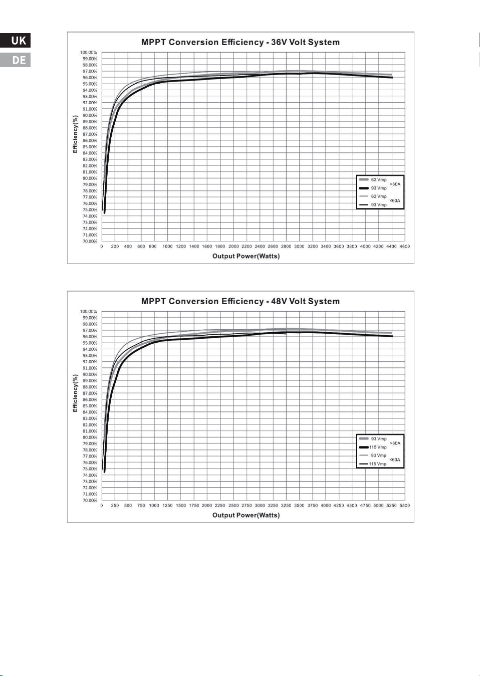
-��-
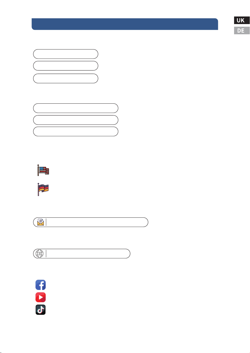
-��-
ⅥI. Technische Unterstützung
�.Renoly Support
Adresse(US): ���� East State Hwy D Suite C Springfield,
Missouri �����
Address(DE): ECO-Worthy Europe GmbH Otto-Hahn-Str. ��
����� Friedrichsdorf - Köppern Germany
Youtube: @ecoworthy
Facebook: https://www.facebook.com/ecoworthy.store/
Tiktok: https://www.tiktok.com/@eco_worthy
�) Telefonnummern des Kundendienstes:
�) Adresse des Unternehmens: USA/Deutschland
�) E-Mail an den Kundendienst:
Tel(DE): +�� ����-����-���
Tel(US/CA): �-���-���-����
Tel(UK): +�� ���� ������
E-mail:customer. service@eco-worthy.com
�) Offizielle Website-Adresse:
Web: https://www.eco-worthy.com/
�) Offizielle soziale Medien:
Öffnungszeiten des Kundendienstes:
Mon-Fri �:�� AM - �:�� PM (CST)US:
Mon-Fri � AM - � PM(GMT)UK:
Mon-Fri � AM - � PM(CET)DE:
Wenn Sie uns telefonisch nicht erreichen, schicken Sie uns bitte eine E-Mail.
Anmerkung:

ECO-WORTHY