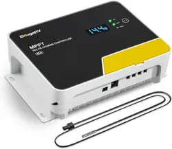
NEGATIVE GROUND
MPPT SOLAR CHARGE CONTROLLER
www.bougerv.com


Content
1. Safety Instructions -----------------------------------------------------------1
2. Technical After Services----------------------------------------------------2
3. Identification Of Parts-----------------------------------------------------3
4. LCD Display Interface Overview------------------------------------------4
5. System Wiring----------------------------------------------------------------5
6. Wiring Instructions--------------------------------------------------------- 5
7. LCD Display Interface-------------------------------------------------------7
7-1. Menu Display Icon------------------------------------------------------------7
7-2. Key Operation-----------------------------------------------------------------7
8. Working Mode----------------------------------------------------------------9
8-1. Working Mode 1: Load mode-----------------------------------------------9
8-2. Working Mode 2: No load mode-----------------------------------------10
8-3. Working Mode 3: Viewing mode-----------------------------------------11
9. Bluetooth module-----------------------------------------------------------12
10. Parameter setting menu-------------------------------------------------13
Menu 1: Battery type setting(Mode 1, Mode 2)-----------------------------13
Menu 2: System voltage(Mode 1, Mode 2)-----------------------------------14
Menu 2.1: Boost charging voltage(Mode 1, Mode 2)-----------------------14
Menu 2.2: Floating charging voltage(Mode 1,Mode 2)--------------------15
Menu 2.3: Boost charging reconnect voltage(Mode 1,Mode 2)---------15
Menu 2.4: Equalizing charging voltage(Mode 1,Mode 2)-----------------15
Menu 2.5: Over-discharge voltage(Mode 1)---------------------------------15
Menu 2.6: Over-discharge delay(Mode 1)------------------------------------16
Menu 2.7: Over-discharge reconnect voltage(Mode 1)--------------------16
Menu 3: Solar panel output voltage(Mode 1,Mode 2,Mode 3)-----------16
Menu 4: Solar panel output current(Mode 1,Mode 2,Mode 3)----------17
Menu 5: Generated energy of the day(Mode 1,Mode 2,Mode 3---------17
Menu 6: Load current(Mode 1,Mode 3)---------------------------------------17
Menu 7: Discharge energy of the day (mode 1, mode 3)-----------------18
Menu 8: The controller temperature(mode 1, mode 2, mode 3)-------18
Menu 9: The battery temperature(mode 1, mode 2,mode 3)----------18

Menu 10: Load mode(mode 1)------------------------------------------------19
Menu 10.1: Light control mode + Duration mode(mode 1)--------------20
Menu 11: Lithium battery low temperature charging protection (mode
1, mode 2)--------------------------------------------------------------------------20
Menu 12: Load short circuit protection(mode 1)---------------------------21
Menu 13: Charging current(mode 1, mode 2)------------------------------21
Menu 14: Constant voltage output of lead acid battery(mode 1, mode
2)------------------------------------------------------------------------------------21
Menu 15: Light control voltage(mode 1)-----------------------------------22
Menu 16: Light control delay(mode 1)---------------------------------------22
Menu 17: Error code(mode 1, mode 2, mode 3)---------------------------22
11. System restart & Factory reset------------------------------------------23
Menu 18: System restart(mode 1, mode 2, mode 3)----------------------23
Menu 19: Factory reset(mode 1, mode 2, mode 3)------------------------23
12. Error Code-------------------------------------------------------------------24
13. Base Specification---------------------------------------------------------26
14. Battery Charge Parameter----------------------------------------------27
15. TTL communication-------------------------------------------------------29
16. RS485------------------------------------------------------------------------ 29
17. CAN communication(Optional)----------------------------------------29
18. Charging-------------------------------------------------------------------- 30
18-1. Charging of lead-acid battery-------------------------------------------30
18-2. Charging of lithium battery---------------------------------------------31
19. Product Dimensions------------------------------------------------------32

1. Safety Instructions
Please save these instructions
1.Read all of the instructions and cautions in the manual before
installation.
2.There are no repairable parts for this controller,do not disassemble
or attempt to repair the controller.
3.Keep the controller from the water.
4.Make sure all connections with controller are tight.
5.Please read the product installation steps to ensure all connections
are correct.
Please follow the safety instructions for operation, the damage caused
by not following the safety instructions shall be borne by the individual.
1-1.General Safety Information
1.NEVER connect the solar panel array to the controller without a
battery. The battery must be connected first.
2.Ensure input voltage does not exceed 100 Voc to prevent permanent
damage.
3.Ensure that the output current of the solar panel does not exceed
the rated charging current of the controller.
1-2.Charge Controller Safety
1 . Do not let the positive (+) and negative (-) terminals of the battery
touch each other.
2. Explosive battery gases may be present while charging. Be certain
there is enough ventilation to release the gases.
3. Be careful when working with large lead-acid batteries. Wear
goggles and have fresh water available in case there is contact with
the battery acid.
4. Over-charging and excessive gas precipitation may damage the
battery plates and activate material shedding on them. Too high of an
equalizing charge or too long of one may cause damage. Please
carefully review the specific requirements of the battery used in the
system.
1-3.Battery Safety
1

2. Technical After Services
BougeRV provides 1-on-1 Solar Solution.
If you have any questions during use, please feel free to contact us:
If you could provide the following relevant information to our email
([email protected]); we can provide you with technical
support solutions faster.
(1)The connection method of the solar panels (series/parallel,
quantity, voltage, power).
(2)The voltage and battery type of the battery.
(3)The pictures or videos of the controller: battery voltage, battery
charging current, the output voltage of the solar panel.
1-408-656-8402
www.bougerv.com
1-669-232-7427
Whataspp
2

3
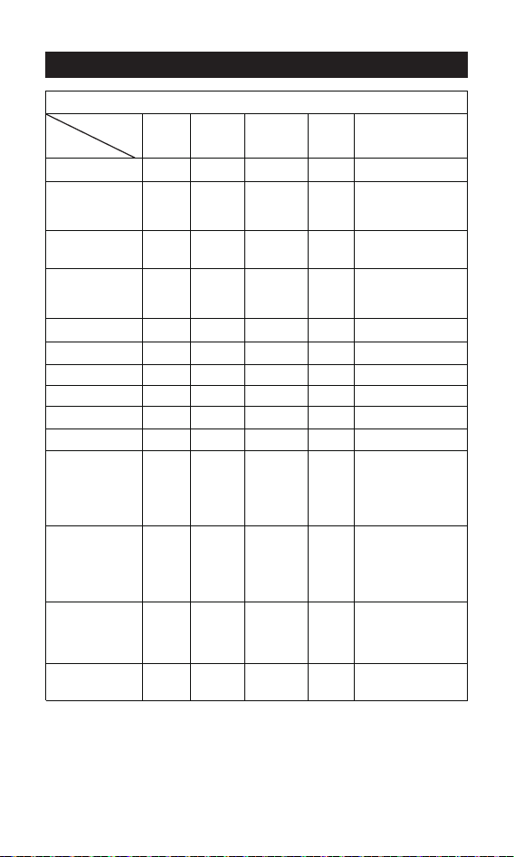
3. Identification Of Parts
1
1
2
3
4
5
6
7
8
9
10
11
2
3
9 10 11
4 5 6 7 8
LCD Display Screen
Button
PV Positive Terminal
PV Negative Terminal
Battery Negative Terminal
Load Negative Terminal
Battery Positive Terminal
Load Positive Terminal
TTL Communication Interface
Temperature sensor Interface
RS485/CAN Communication Interface
4
1
2
3
4
5
6
7
8
9
10
11
12
13
14
15
16
17
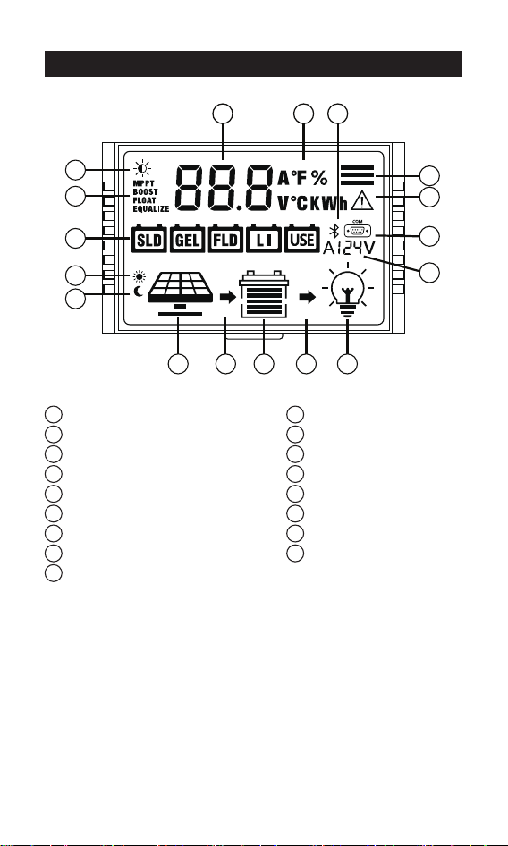
Daytime icon
Night icon
Solar panel
Battery
Load
Charging state
Discharging state
System voltage
RS485/CAN communication icon
Bluetooth icon
Battery type
Charging stage
Load light control icon
Parameter
Unit symbol
Operating mode
Warning icon
4. LCD Display Interface Overview
11
9
8
17
16
2
12
13
1
3 6 4 7 5
14 15 10
16 9
81
5
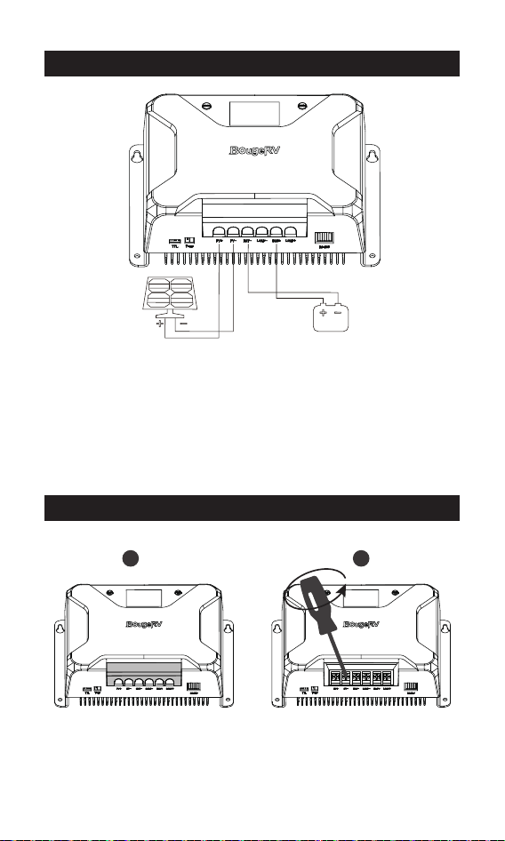
1. The positive and negative poles of the battery must be connected
to the battery terminals of the controller first.
2. Finally, connect the positive and negative poles of the solar panel to
the PV terminals of the controller.
3.Make sure that the Bluetooth of the mobile phone is turned on, and
open the APP "Solar" to enter the setting interface.
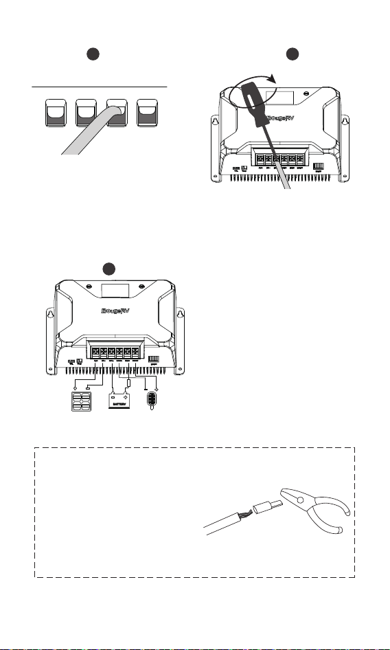
5.System Wiring
6.Wiring Instructions
1.Remove the plastic cover.(Pick up) 2.Unscrew the screws.
(Counterclockwise)
1 2
6
5. Check the wiring condition
and put the plastic cover back.
Please strictly follow the above
sequence for connection.
Note:
During the wiring process, the
attached terminal lugs can be
used for connection. After
stripping the wire, put it into the
terminal lugs and squeeze it with
a crimping pliers.
3
5
4
3. Plug the cable into the
correct port.
4. Tighten the screws.
(Clockwise)
fuse s
7
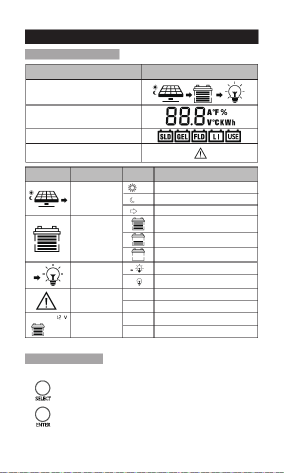
7. LCD Display Interface
Press the button to scroll the menu backward to the
previous menu.
Press the button to scroll the menu forward to the
next menu.
Indicate And Warning
BAT Type
Display Section
Charge And Load Status
Parameter
Status
System Error
Indication
Voltage
Indication
On
OFF
12V
24V
12V System Voltage
24V System Voltage
System Error - Check Error Code
System Normally
Status Icon
Indication
Status
Description
Day Night
And Charge
Indication
Battery
Indication
Load
Indication
On
On
On
Daylight Detected
No Daylight Detected
Solar Charging Battery
Battery Voltage is Hight
Battery Voltage is Middle
Battery Voltage is Low
Load On
Load Off
7-1.Menu Display Icon
7-2.Key Operation
1. Menu Switching
1. Safety Instructions -----------------------------------------------------------1
2. Technical After Services----------------------------------------------------2
3. Identification Of Parts-----------------------------------------------------3
4. LCD Display Interface Overview------------------------------------------4
5. System Wiring----------------------------------------------------------------5
6. Wiring Instructions--------------------------------------------------------- 5
7. LCD Display Interface-------------------------------------------------------7
7-1. Menu Display Icon------------------------------------------------------------7
7-2. Key Operation-----------------------------------------------------------------7
8. Working Mode----------------------------------------------------------------9
8-1. Working Mode 1: Load mode-----------------------------------------------9
8-2. Working Mode 2: No load mode-----------------------------------------10
8-3. Working Mode 3: Viewing mode-----------------------------------------11
9. Bluetooth module-----------------------------------------------------------12
10. Parameter setting menu-------------------------------------------------13
Menu 1: Battery type setting(Mode 1, Mode 2)-----------------------------13
Menu 2: System voltage(Mode 1, Mode 2)-----------------------------------14
Menu 2.1: Boost charging voltage(Mode 1, Mode 2)-----------------------14
Menu 2.2: Floating charging voltage(Mode 1,Mode 2)--------------------15
Menu 2.3: Boost charging reconnect voltage(Mode 1,Mode 2)---------15
Menu 2.4: Equalizing charging voltage(Mode 1,Mode 2)-----------------15
Menu 2.5: Over-discharge voltage(Mode 1)---------------------------------15
Menu 2.6: Over-discharge delay(Mode 1)------------------------------------16
Menu 2.7: Over-discharge reconnect voltage(Mode 1)--------------------16
Menu 3: Solar panel output voltage(Mode 1,Mode 2,Mode 3)-----------16
Menu 4: Solar panel output current(Mode 1,Mode 2,Mode 3)----------17
Menu 5: Generated energy of the day(Mode 1,Mode 2,Mode 3---------17
Menu 6: Load current(Mode 1,Mode 3)---------------------------------------17
Menu 7: Discharge energy of the day (mode 1, mode 3)-----------------18
Menu 8: The controller temperature(mode 1, mode 2, mode 3)-------18
Menu 9: The battery temperature(mode 1, mode 2,mode 3)----------18
8
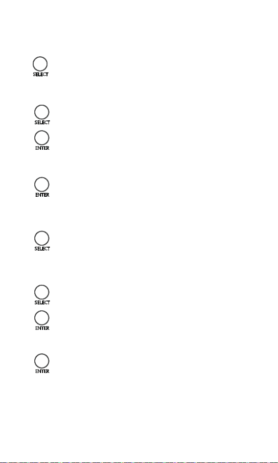
In the menu interface, press and hold the button for 2s to
enter the menu parameter adjustment interface.
2. Enter the Parameter Setting Interface
Enter the parameter setting interface, press the button to
adjust the parameter.(Decrease)
Enter the parameter setting interface, click the button to
adjust the parameter.(Add)
3. Adjust Parameters
Enter the parameter setting interface, press the button to
adjust the parameter.(Decrease)
Enter the parameter setting interface, click the button to
adjust the parameter.(Add)
After adjusting the parameters, press and hold the button
for 2s to confirm the setting parameters.
After adjusting the parameters, press and hold the button
for 2s to confirm the setting parameters.
4. Save Parameters
5.1 Enter the working mode setting interface
On the main menu interface, press and hold the button
for 5s to enter the working mode setting interface, and the
working mode icon will display.
5.2 Adjust working mode
5.3 Save working mode setting
5. Working mode setting
9
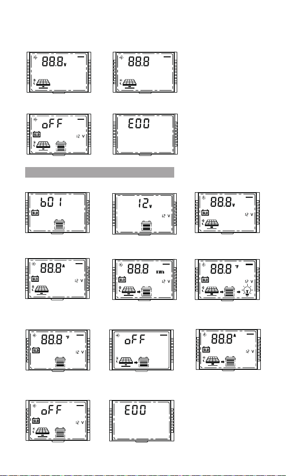
Charging Stage Menu
16 9
81
16 9
81
16 9
81
16 9
81
Menu 2.1:
Boost charging voltage
Menu 2.3:
Boost charging
reconnect voltage
Menu 2.4:
Equalizing charging
voltage
Menu 2.5:
Over-discharge voltage
16 9
81
Menu 2.6:
Over-discharge delay
Menu 2.7:
Over-discharge r
econnect voltage
Menu 2.2:
Floating charging voltage
16 9
81
16 9
81
16 9
81
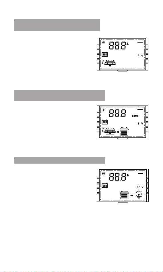
Menu 4:
Solar panel output current
16 9
81
Menu 5:
Generated energy of the day
16 9
81
Menu 6:
Load current
16 9
81
Menu 7:
Discharge energy of the day
16 9
81
Menu 8:
The controller temperature
16 9
81
Menu 9:
The battery temperature
Menu 10:
Load mode
16 9
81
Menu 10.1:
Light control mode +
Duration mode
16 9
81
Menu 11:
Lithium battery low
temperature charging protection
16 9
81
Menu 12:
Load short circuit protection
16 9
81
Menu 13:
Charging current
16 9
81
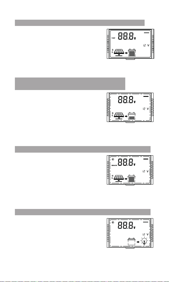
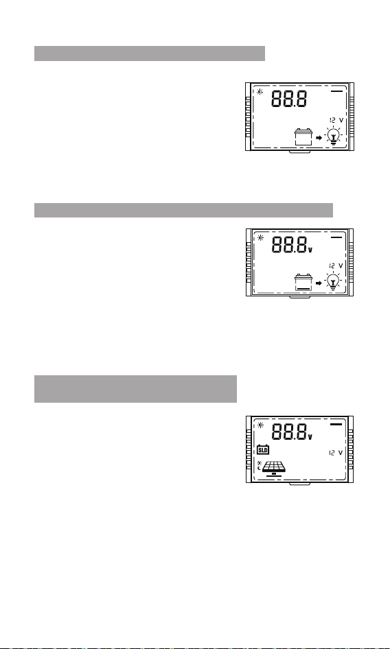
8-1 Working Mode 1: Load mode
8. Working Mode
16 9
81
Menu 2:
System voltage
16 9
81
Menu 3:
Solar panel output voltage
Menu 1:
Battery type setting
16 9
81
10
8-2 Working Mode 2: No load mode
16 9
81
16 9
81
16 9
81
16 9
81
16 9
81
Menu 1:
Battery type setting
Menu 3:
Solar panel output voltage
Menu 4:
Solar panel output current
Menu 5:
Generated energy of the day
Menu 8:
The controller temperature
Menu 9:
The battery temperature
Menu 13:
Charging current
Menu 17:
Error code
Menu 14:
Constant voltage output of
lead acid battery
Menu 11:
Lithium battery low
temperature charging protection
16 9
81
16 9
81
16 9
81
16 9
81
16 9
81
16 9
81
Menu 15:
Light control voltage
16 9
81
Menu 16:
Light control delay
Menu 14:
Constant voltage
output of lead acid battery
16 9
81
Menu 17:
Error code
16 9
81
16 9
81
Menu 2:
System voltage
11
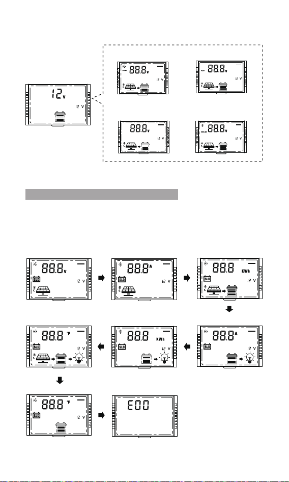
It is recommended to switch to mode 3 after setting the
system parameters, so that it is convenient to check the
daily work of the PV system.
8-3 Working Mode 3: Viewing mode
16 9
81
Menu 2.1:
Boost charging voltage
16 9
81
Menu 2.4:
Equalizing charging
voltage
Menu 2.2:
Floating charging voltage
16 9
81
Menu 2.3:
Boost charging
reconnect voltage
16 9
81
16 9
81
Menu 3:
Solar panel output voltage
16 9
81
Menu 4:
Solar panel output current
16 9
81
Menu 5:
Generated energy of the day
16 9
81
Menu 6:
Load current
16 9
81
Menu 7:
Discharge energy of the day
16 9
81
Menu 8:
The controller temperature
16 9
81
Menu 9:
The battery temperature
Menu 17:
Error code
16 9
81
16 9
81
Menu 2: System voltage

12
9. Bluetooth module
Built-in Bluetooth communication function can monitor the
operation data, fault status and adjust the operation parameters of
the controller in real time through mobile APP.
Scan the QR code to download the application;
Search for "Solar App" in the APP Store (for IOS devices) or Google
Play (for Android devices.
Download
IOS & Android
Solar APP
13
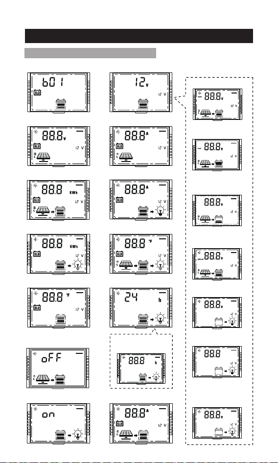
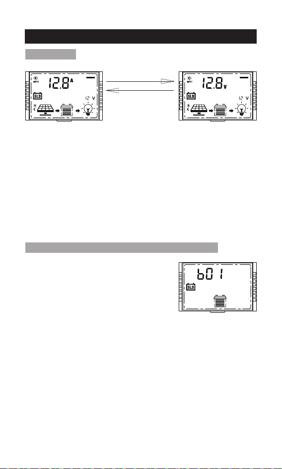
10. Parameter setting menu
Main menu (current)
① SLD =Sealed lead acid battery
② GEL=GEL battery
③ FLD=Flooded lead acid battery
④ LI=Lithium iron phosphate battery/LiFePO4
⑤ USE=Custom battery
Setting method:
1. On the battery type menu, press and hold [SELECT] for more than 2s
until the parameter flashes to enter the battery type parameter setting
interface.
2. On the battery type parameter setting interface, single press
[SELECT] or [ENTER] to adjust the parameters.
3. After completing the parameter setting, press and hold [ENTER] for
more than 2s until the parameter does not flash, and the parameter
setting saves successfully; single press [ENTER] to switch to the next
menu or automatically jump back to the main menu after 10s of no
operation.
1.On the parameter setting interface, if there is no operation for 10s, it
will automatically jump back to the main menu.
2.On the parameter setting interface, if the parameter is not confirmed,
the parameter will keep flashing, confirm until the parameter does not
flash, indicating that the parameter setting is successful.
3.The backlight turns off after 10s of no operation.
Main Menu
Menu 1: Battery type setting (Mode 1, Mode 2)
Main menu (voltage)
Automatic loop
playback every 5s
16 9
81
16 9
81
16 9
81
14
Setting method:
1. On the system voltage menu, press and hold [SELECT] for more
than 2s until the parameter flashes to enter the system voltage
parameter setting interface.
2. On the system voltage parameter setting interface, single press
[SELECT] or [ENTER] to adjust the parameters.
3. After completing the parameter setting, press and hold [ENTER] for
more than 2s until the parameter does not flash, and the parameter
setting saves successfully; single press [ENTER] to switch to the next
menu or automatically jump back to the main menu after 10s of no
operation.
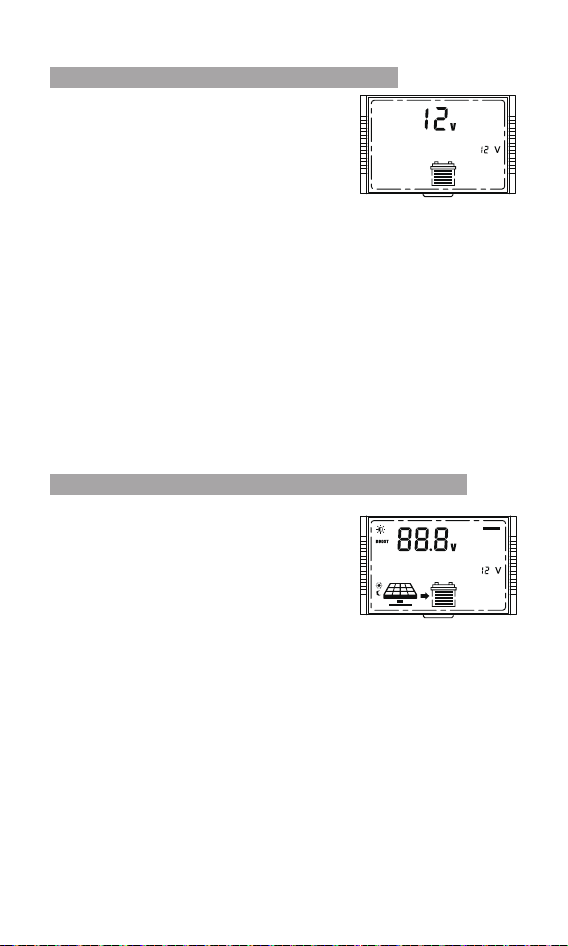
Note: The system voltage will take effect after the system voltage
setting saves successfully.
1. Automatically identify voltage
(only applicable to the lead-acid battery)
2. 12V
3. 24V
①12V system:
9-17V, 0.1V step (default 14.4V)
②24V system:
18-34V, 0.2V step (default 28.8V)
Note:
This menu will only appear when the battery type is set to LI or USE.
Setting method:
1. On the boost charging voltage menu, press and hold [SELECT] for
more than 2s until the parameter flashes to enter the boost charging
voltage parameter setting interface.
2. On the boost charging voltage parameter setting interface, single
press [SELECT] or [ENTER] to adjust the parameters.
3. After completing the parameter setting, press and hold [ENTER] for
more than 2s until the parameter does not flash, and the parameter
setting is successful; single press [ENTER] to switch to the next menu
or automatically jump back to the main menu after 10s of no operation.
Menu 2: System voltage(Mode 1, Mode 2)
Menu 2.1: Boost charging voltage(Mode 1, Mode 2)
16 9
81
16 9
81
15
Menu 2.3: Boost charging reconnect voltage
(Mode 1, Mode 2)
Note:
This menu will only appear when the battery type is set to LI or USE.
Setting method: Same as above.
①12V system:
9-17V, 0.1V step (default 13.2V)
②24V system:
18-34V, 0.2V step (default 26.4V)
16 9
81
Menu 2.4: Equalizing charging voltage(Mode 1, Mode 2)
Note:
This menu will only appear when the battery type is set to USE.
Setting method: Same as above.
①12V system:
9-17V, 0.1V step (default 14.6V)
②24V system:
18-34V, 0.2V step (default 29.2V)
16 9
81
Menu 2.5: Over-discharge voltage(Mode 1)
Note:
This menu will only appear when the battery type is set to LI or USE.
Setting method: Same as above.
①12V system:
9-17V, 0.1V step (default 11.1V)
②24V system:
18-34V, 0.2V step (default 22.2V)
16 9
81
Menu 2.2: Floating charging voltage(Mode 1, Mode 2)
Note:
This menu will only appear when the battery type is set to USE.
Setting method: Same as above.
16 9
81
①12V system:
9-17V, 0.1V step (default 13.8V)
②24V system:
18-34V, 0.2V step (default 27.6V)
16
Note:
This menu will only appear when the battery
type is set to USE.
Setting method: Same as above.
1-60s. (default 5s)
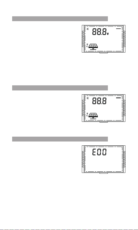
Display solar panel output voltage.
Note:
The voltage value only can be read, but
cannot be adjusted;
Setting method: Same as above.
①12V system:
9-17V, 0.1V step (default 12.6V)
②24V system:
18-34V, 0.2V step (default 25.2V)
Note:
This menu will only appear when the battery type is set to LI or USE.
Setting method: Same as above.
Menu 2.6: Over-discharge delay(Mode 1)
Menu 2.7: Over-discharge reconnect voltage(Mode 1)
Menu 3: Solar panel output voltage
(Mode 1, Mode 2, Mode 3)
16 9
81
16 9
81
16 9
81
17
Display solar panel output current.
Note:
The current value only can be read, but
cannot be adjusted;
Setting method: Same as above.
Displays the output current at the load
port of the controller.
Note:
The value only can be read, but cannot be
adjusted;
Setting method: Same as above.
Display generated energy of the day.
Note:
The value only can be read, but cannot
be adjusted;
Setting method: Same as above.
Menu 4: Solar panel output current
(Mode 1,Mode 2,Mode 3)
Menu 5: Generated energy of the day
(Mode 1, Mode 2, Mode 3)
Menu 6: Load current(Mode 1, Mode 3)
16 9
81
16 9
81
16 9
81
18
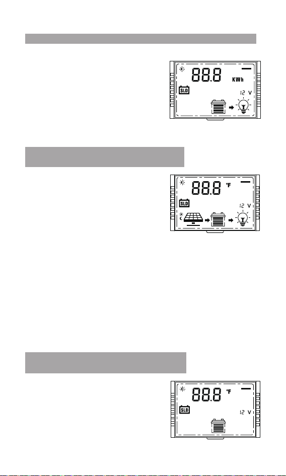
Display the output energy of the
controller load port of the day.
Note: The value only can be read, but
cannot be adjusted;
Setting method: Same as above.
Display the battery temperature.
①°F (defaults)
②°C
Setting method: Same as above.
Display the controller temperature.
①°F (defaults)
②°C
Setting method:
1. On the controller temperature menu, press and hold [SELECT] for
more than 2s until the parameter flashes to enter the controller
temperature parameter setting interface.
2. On the controller temperature parameter setting interface, single
press [SELECT] or [ENTER] to choose the °F or °C .
3. After completing the parameter setting, press and hold [ENTER] for
more than 2s until the parameter does not flash, and the parameter
setting is successful; single press [ENTER] to switch to the next menu
or automatically jump back to the main menu after 10s of no
operation.
Menu 7: Discharge energy of the day(mode 1, mode 3)
Menu 8: The controller temperature
(mode 1, mode 2,mode 3)
Menu 9:The battery temperature
(mode 1, mode 2,mode 3)
16 9
81
16 9
81
16 9
81
19
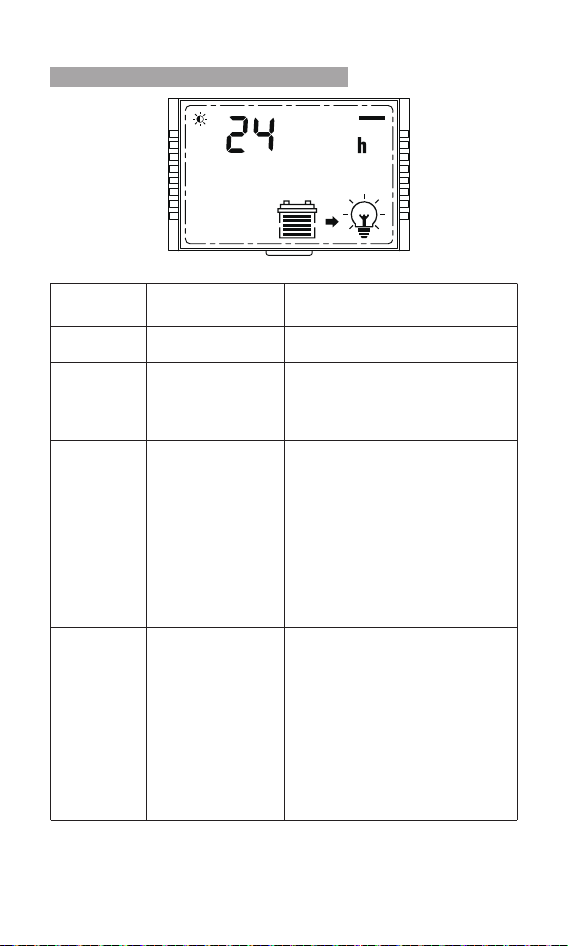
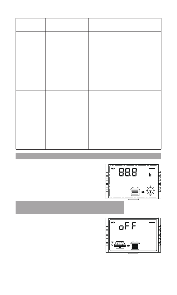
Menu 10: Load mode(mode 1)
LCD screen
number
Load mode Description
24h
000
0h
Normal
on mode
Manual mode
Pure light
control, turn on
the load at night
and turn off the
load during the
day
The load is always on.
When there is no sunlight, the
solar panel voltage is less than
the light control on voltage, the
controller delays for 1 minute
and then turns on the load ;
When there is sunlight, the solar
panel voltage is higher than the
light control off voltage,the
controller delays for 1 minute
and then turns off the load ;
00h
Pure light control
turns on the load
during the day
and turns off the
load at night
When there is no sunlight, the
solar panel voltage is less than
the light control on voltage, the
controller delays for 1 minute
and then turns off the load ;
When there is sunlight, the solar
panel voltage is higher than the
light control off voltage,the
controller delays for 1 minute
and then turns on the load
On the main menu interface,
press and hold [ENTER] for more
than 2s to turn on/off the load.
(not affected by light control)
16 9
81
Setting method: Same as above.
20
Note:① Make sure to connect the temperature sensor when turn on
the lithium battery low temperature charging protection.
②This menu will only appear when the battery type is set to LI or USE.
Setting method: Same as above.
LCD screen
number
Load
mode
Description
display: 11,
setting is
usually 1-14h
display: 22,
setting is
usually
01-014h
Pure light
control,turn on
the load at night
and turn off the
load during the
day + time
control
Pure light control
turns on the load
during the day
and turns off the
load at night +
time control
When there is no sunlight, the
solar panel voltage is less than
the light control on voltage, the
controller delays for 1 minute
and then turns off the load ;
When there is sunlight, the solar
panel voltage is higher than the
light control off voltage,the
controller delays for 1 minute
and then turns on the load.
When there is no sunlight, the
solar panel voltage is less than
the light control on voltage, the
controller delays for 1 minute
and then turns on the load ;
When there is sunlight, the solar
panel voltage is higher than the
light control off voltage,the
controller delays for 1 minute
and then turns off the load;
Menu 10.1: Light control mode + Duration mode(mode 1)
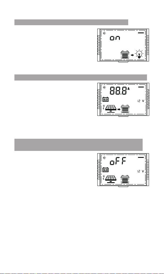
Menu 11: Lithium battery low temperature
charging protection (mode 1, mode 2)
The adjustment range is 1-14 hours.
①When menu 10 selects 11: 1-14h, 1 step
(default 1h)
②When menu 10 selects 22: 01-014h, 1
step (default 1h)
Setting method: Same as above.
①oFF: Turn off protection (default)
②on: Turn on the protection (the
temperature sensor detects that the
temperature is ≤0°C(32°F), start the
low temperature charging protection,
and do not charge the lithium battery
until the battery temperature returns to
2°C(35.6°F).
16 9
81
16 9
81
21
①on: open load short-circuit protection
(default )
②oFF: close load short-circuit
protection
Setting method: Same as above.
Menu 12: Load short circuit protection(mode 1)
16 9
81
Adjust current range: 0——rated current
(for example:the 60A controller,
adjusting current range is 0-60A)
① Set 0:No charging
② Set 1——rated current:Limit charging
current(1 step)
Default: rated current
Setting method: Same as above.
Menu 13: Charging current (mode 1, mode 2)
16 9
81
① oFF: The controller can not output
without battery. (default)
②on: The controller can output without
battery.
Note: When the lead-acid battery cannot
work due to over-discharge, this function
can be turned on, and the controller can
activate the lead-acid battery with
constant voltage output lead acid battery
activation.
Setting method: Same as above.
Menu 14: Constant voltage output of lead acid battery
(mode 1, mode 2)
16 9
81
22
①12V system voltage: 5-11V, 5V(default)
②24V system voltage: 10-22V,
10V(default)
Note:
①Light control on: The solar panel
voltage is less than the adjusting
voltage.
② If it is the system of 24V, relevant
voltage points shall be automatically
multiplied by 2.
Setting method: Same as above.
Menu 15: Light control voltage(mode 1)
16 9
81
Adjust voltage range: 0-960s, step 60s.
Default:60s.
Note: Minimum duration required to meet
the light control on or off condition.
Setting method: Same as above.
Menu 16: Light control delay(mode 1)
16 9
81
E00: The system is working normally.
Note: It can only be viewed, and it shows
that the E00 system is working normally,
and other error codes need to be checked.
Setting method: Same as above.
Menu 17: Error code(mode 1, mode 2, mode 3)
16 9
81
23
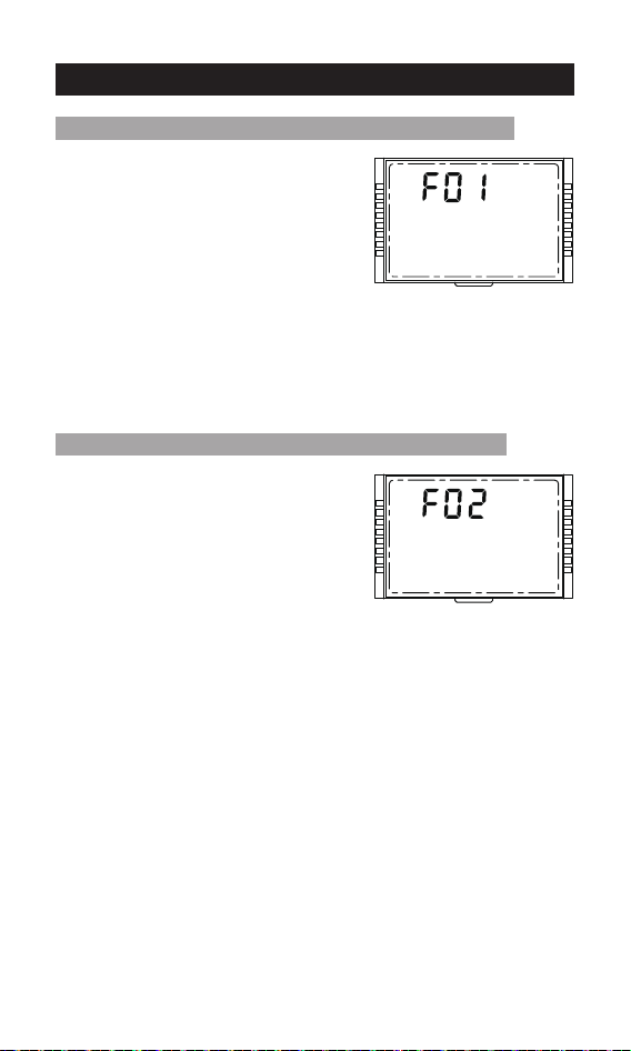
On the main menu, press and hold
[ENTER] for more than 5s until the
parameter flashes to enter the parameter
setting interface.
2. On the parameter setting interface,
single press [SELECT] or [ENTER] to
choose F01 or F02.
3. After completing the parameter setting,
press and hold [ENTER] for more than 2s
until the parameter does not flash, and the
parameter setting is successful.
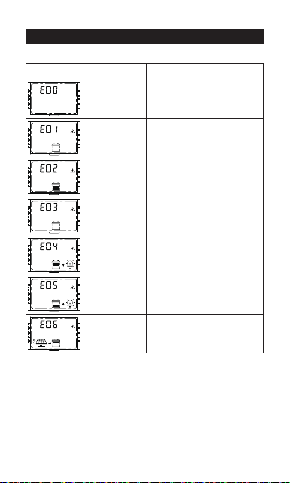
Menu 18: System restart(mode 1, mode 2, mode 3)
F02
Setting method: Same as above.
Menu 19: Factory reset (mode 1, mode 2, mode 3)
11. System restart & Factory reset
16 9
81
16 9
81
24
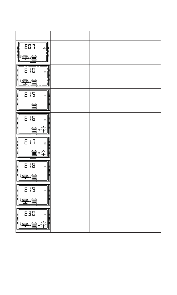
12. Error Code
Solution
Cause of failureError code
Normal system
Battery
over-discharge
Battery
over-voltage
Battery
under-voltage
warning
Load over-current
Load short-circuited
/
1.Turn off load output, after the battery
voltage recover to the over -discharge
reconnect voltage, relieve
over-discharge to restore load output.
2.The battery voltage does not match
the system, check the system voltage.
Stop charging, check and find out the
cause of high battery voltage. The
charging will be automatically
restored after the battery voltage is
lowered.
Battery voltage below undervoltage
warning threshold, warning only.
Turn off load output, and perform
delay protection by a multiple of
rated current.
Controller high
temperature
abnormal state
Charging will be stopped when the
controller temperature is above 75°C
and recover when it is below 70°C.
Turn off load output.
16 9
81
16 9
81
16 9
81
16 9
81
16 9
81
16 9
81
16 9
81
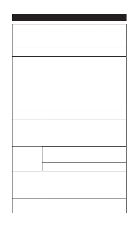
25
Solution
Cause of failureError code
16 9
81
Battery low
temperature
charging
protection
Charging will be stopped when the
battery temperature is below -35°C
and resumed when it is above -30°C
Battery low
temperature
discharging
protection
Load output will be turned off when
the battery temperature is below -35°C
and resumed when it is above -30°C
16 9
81
Charging and
discharging
disabled by
system setting
System charging or discharging failure.
16 9
81
16 9
81
Overcharge
protection
Turn off charging, the battery voltage
is higher than the over-voltage voltage,
turn off charging, the battery voltage
drops, and recover after 10s.
16 9
81
Battery high
temperature
discharging
protection
Load output will be turned off when
the battery temperature is above 75°C
and recover when it is below 70°C.
Solar panel
over-voltage
Stop charging when the output
voltage of the solar panel is higher
than 95V, and recover charging when
the voltage is lower than 90V.
16 9
81
Battery high
temperature
charging
protection
Charging will be stopped when
the battery temperature is above 75°C
and resumed when it is below 70°C.
16 9
81
16 9
81
Lead acid battery
is not connected
In lead-acid battery mode, the battery
is damaged or not connected.
26
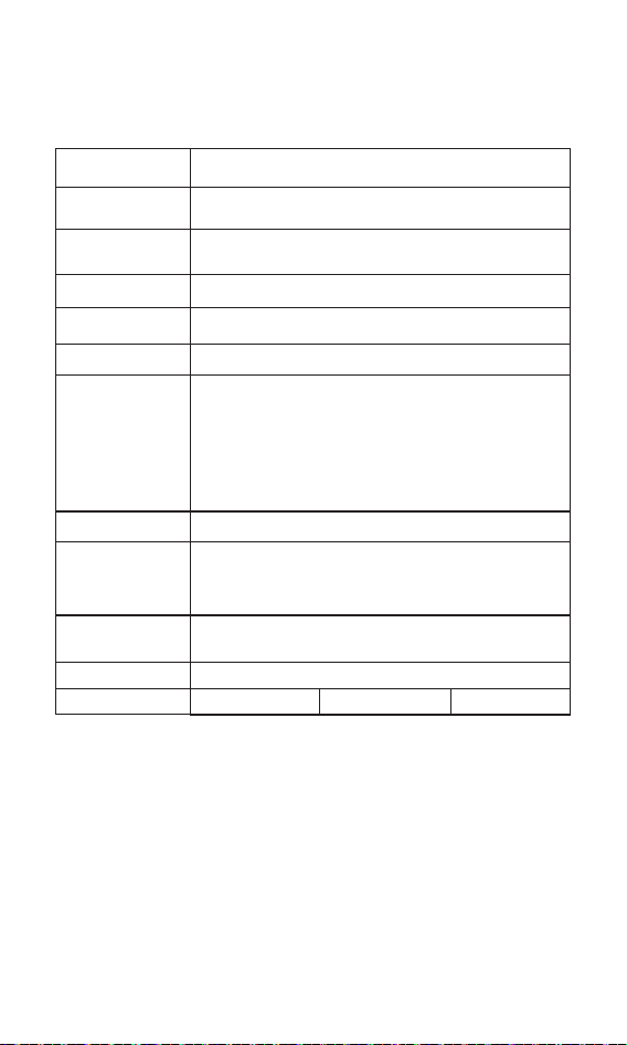
13. Base Specification
30A 60A
450W/12V
900W/24V
900W/12V
1800W/24V
12V/24V
40A
600W/12V
1200W/24V
SLD/GEL/FLD/LI/USE,SLD as default
100V (95V protection, 90V recovery)
Model BJ2430N BJ2440N BJ2460N
(Battery voltage +2V)~72V
>99%
>95%
20A
√
√
√
√
√
√
System voltage
Battery Type
Maximum input
of PV system
Maximum PV
input voltage
MPPT operating
voltage range
MPPT tracking
efficiency
Charging
conversion
efficiency
Rated load
current
Charging
current setting
Lithium battery
low temperature
charging
protection
Constant voltage
output setting
Temperature
unit setting
Overload/
Short-circuit
protection
Charging
temperature
compensation of
lead-acid battery
Rated charging
current
27
built-in bluetooth
RJ45 interface, optional (RV-C protocol)
Save the last 200 days of historical data
Grounding of common negative electrode
-31°F~149°F(-35°C~65°C)
IP34
1076g 1789g 2503g
Natural heat dissipation
Baud rate: 9,600 bps
RJ45 interface, with power output 5V/200 mA,The
baud rate is 9,600 bps by default, adjustable.
PV overvoltage protection, PV reverse connection
protection, PV short circuit protection, night
reverse charging protection, input power limit
protection, over-temperature protection, load
short-circuit protection, overload protection,
battery over-voltage/over-discharge protection,
battery reverse connection protection, battery end
short circuit protection.
TTL
communication
8V-32V
Battery operating
voltage range
RS485
communication
Bluetooth
communication
CAN
communication
Historical data
Protection
function
Grounding type
Protection grade
Cooling mode
Operating
ambient
temperature
range
Weight
28
14. Battery Charge Parameter
Battery parameters
Battery Type
Setting/
Voltage
Sealed
Lead-Acid
SLD
Gel lead-acid
battery
Flooded lead
-acid battery
Lithium
battery
Custom
battery
USE
Overvoltage
disconnect voltage
16.0V 16.0V 16.0V 16.0V 16.0V
0-17V (Default 14.6V)
Note: Set to 0, (Do not
turn on the equalization
charging function
Equalizing voltage 14.6V -- 14.8V --
9-17V (Default 14.4V)
Boost voltage 14.4V 14.2V 14.6V
9-17V
(Default
14.4V)
0-17V (Default 13.8V)
Note: Set to 0, (Do not
turn on the float
charging function)
13.8V 13.8V 13.8V --
9-17V (Default 13.2V)
Boost charging
reconnect voltage
13.2V 13.2V 13.2V 13.2V
9-17V (Default 12.6V)
Over-discharge
restoring voltage
12.6V 12.6V 12.6V 12.6V
12.0V
Under-voltage
alarming voltage
12.0V 12.0V 12.0V 12.0V
9-17V (Default 11.1V)
Over-discharge
voltage
11.1V 11.1V 1 1.1V 11.1V
10.6V
Over-discharge
cut off voltage
10.6V 10.6V 10.6V 10.6V
1-60s (Default 5s)
Over-discharge
delay
5s 5s 5s 5s
30 days
Note: If the equalization
charging voltage is set
to 0, there is no
equalization charging
interval (/)
Equa
lizing charging
interval
30 days -- 30 days --
120 min
Note: If the equalization
charging voltage is set
to 0, there is no
equalization charging
duration (/)
Equalizing charging
duration
120 min -- 120 min --
120 min
Note: If the equalization
charging voltage is set
to 0, there is no boost
charging duration (/)
Boost charging
duration
120 min 120 min 120 min --
Defaul:-3
Temperature
compensation
(mV/℃ /2V)
-3 -3 -3 --
①
①
Float charge
voltage
①
①
①
①
①
①
① The above values ar
e the parameters at 25°C/12V; if it is the syst
em of 24V, relevant voltage
points shall be automatically multiplied by 2.
Note:
①
GEL
FLD
LI
factor
29
15. TTL communication
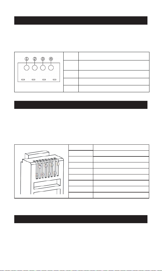
16. RS485
17. CAN communication(Optional)
1) Default baud rate: 9,600 bps; check bit: none; data bit: 8 bit;
stop bit: 1 bit
2) Communication power supply output specification:
(8.5V±1V)/: 100mA
1) RS485 communication:
Default baud rate: 9,600 bps; parity bit: none; data bit: 8 bit;
stop bit: 1 bit Interface type: RJ45, communication power
supply output specification: 5V/200mA
2) RJ45 interface communication line sequence definition:
1) CAN communication: support RV-C protocol
TTL-COM
①
②
③
④
GND
S/N
Definition
VCC: communication power
supply output
RX: controller data receiving end
TX: controller data transmitting end
Definition
S/N
①
②
③
④
⑤
⑥
⑦
⑧
Positive terminal
D+
D-
Power ground/signal ground
NC
NC
CAN_H
CAN_L
Note: NC represents an empty pin, which means that the pin is not connected.
30
18. Charging
Select such battery types as SLD/FLD/GEL/USE, and select the
appropriate system voltage.
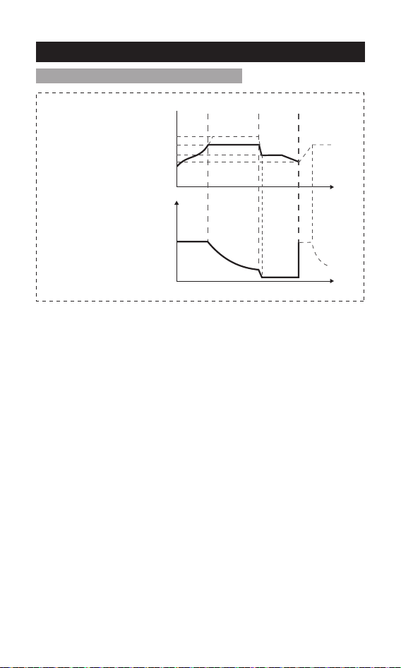
As shown in Fig. 18-1, the charging stages of lead-acid battery are:
MPPT charging, constant voltage charging (equalizing/boost/floating
charging), and current-limiting charging.
The constant voltage charging is divided into three stages: equalizing
charging, boost charging and floating charging
[MPPT charging] When the battery voltage has not reached the
target constant voltage value, the controller will perform MPPT
charging. When the battery voltage reaches the constant voltage
value, it will automatically exit MPPT charging and switch to constant
voltage charging (equalizing/boosting/floating charging).
[Equalizing charging] Regular equalizing charging is good for some
batteries. Equalizing charging is mainly to make the charging voltage
of battery higher than the standard supplementary voltage, besides,
it can vaporize the battery electrolyte to balance the battery voltage
and complete relevant chemical reaction. Equalizing charging and
boosting charging are not repeated during one full charging to avoid
excessive gas evolution or overheating of the battery.
Notes:
1) Since the equalizing charging of floored lead-acid battery produces
explosive gas, the battery compartment must be well ventilated.
2) Although the equalizing charging elevates the battery voltage, it
may damage the level of sensitive DC loads, therefore, it is necessary
to verify that the allowable input voltage of all loads in the system is
greater than the set battery voltage value in equalizing charging.
18-1: Charging of lead-acid battery
Charging voltage
Constant
voltage
charging
Floating
charging
Equalizing charging voltage
MPPT
Boost charging voltage
Floating charging voltage
Charging reconnect voltage
Time
Time
Fig. 18-1 Charging curve of lead acid battery
31
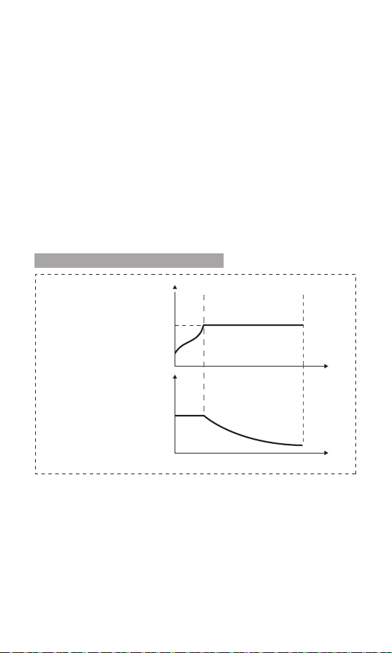
Select such battery types as LI, and select the system voltage from
12V/24V.
As shown in Fig. 18-2, the charging stages of lithium battery are:
MPPT charging/boost charging/current-limiting charging.
[MPPT charging] When the battery voltage does not reach the target
constant voltage value, the controller conducts MPPT charging to
charge the battery with maximum solar power, when reaches, it
automatically switches to boost charging.
[Boost charging] In the boost charging stage of lithium battery,
when the battery voltage is lower than the boost charging voltage,
the system conducts MPPT charging or current-limiting charging,
when reaches, it switches to boost charging.
18-2: Charging of lithium battery
Charging voltage
Charging current
Boost charging voltage
MPPT
Constant voltage
charging
Time
Time
Fig. 18-2 Charging curve of lithium battery
3) Excessive charging and excessive gas evolution may damage the
battery plate and cause the active substances on the battery plate to
fall off.Besides, excessive high equalizing charging voltage or
excessive long equalizing charging duration may damage the
battery. Please set relevant parameters according to the specifica-
tions of the battery used in the system.
[Boost charging] The duration of boost charging is 2 h (default).
When the duration reaches the set value, the system will switch to
floating charging.
[Floating charging] Floating charging is the last constant voltage
charging stage in the charging cycle of lead-acid battery. The
controller keeps the charging voltage constant at the floating
charging voltage. At this stage, the battery is charged with a very
weak current to ensure that the battery is in full-charging. When the
battery voltage is as low as the reconnect voltage of boost charging,
the system will exit the floating charging stage and re-enter the next
charging cycle.
32
BJ2430N
19. Product Dimensions
Model: BJ2430N
Product dimension: 185*133*75mm
Fixed hole position: φ5mm
185mm
172mm
133mm
107mm
75mm
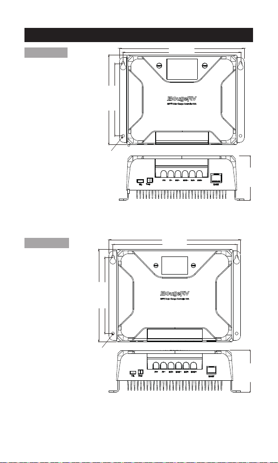
Model: BJ2440N
Product dimension: 227*159.6*75mm
Fixed hole position: φ5mm
BJ2440N
227mm
214mm
159.6mm
132mm
75mm
φ5mm
φ5mm
33
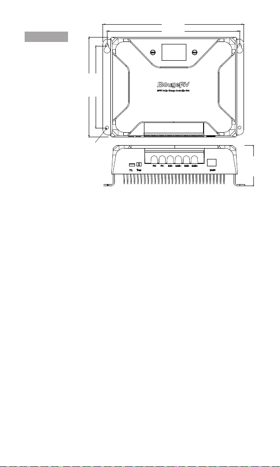
Model: BJ2460N
Product dimension: 263*186*85mm
Fixed hole position: φ5mm
BJ2460N
263mm
248mm
186mm
154mm
85mm
φ5mm