Installation and Operation Manual
THE EXPERTS IN ROOM AIR CONDITIONING
230 VOLT PDE07K3SGR3, PDE09K3SGR3, PDE12K3SGR3, PDE15K3SGR3
265 VOLT PDE07R3SGR3, PDH09R3SGR3, PDE12R3SGR3, PDE15R3SGR3
Cool with Electric Heat Models
ZoneAire Premier
®
R-32 Series
PTAC
Packaged Terminal Air
Conditioners & Heat Pumps
94141010_02
230 VOLT PDH07R3SGR3, PDH09R3SGR3, PDH12R3SGR3, PDH15R3SGR3
265 VOLT PDH09R3SGR3, PDH12R3SGR3, PDH15R3SGR3
Heat Pump Models
2
A. IMPORTANT SAFETY AND GENERAL INFORMATION ................. 3
A.1 Introduction ............................................................................. 3
A.2 • Safety Warnings ................................................................... 3
A.3 Warning For Using R32 Refrigerant ..................................... 5
A.4 Importance of a Quality Installation ..................................... 7
A.5 Product Inspection ................................................................. 7
A.5 Model Identification Guide ..................................................... 7
A.6 Unit Features ........................................................................... 7
B. SPECIFICATIONS ................................................................................. 9
B.1 Major Components and Dimensions .................................... 9
B.2 Product Data Information ..................................................... 9
C. INSTALLATION OF THE UNIT ...........................................................10
C.1 Pre-Installation Checkpoints ...............................................10
C.3 Choosing a Location ..............................................................11
C.4 Install Unit .............................................................................13
C.4.2 External Drain Kit Installation .........................................14
C.4.3 Wall Sleeve Installation Instructions (PDXWS) ..............................15
C.4.4 Standard Grille Instructions .............................................19
C.5 Chassis Install ....................................................................... 20
E. ELECTRICAL ........................................................................................ 22
E.1 Electrical Safety Information ...............................................22
E.2 Power Cord LCDI Test ......................................................... 22
E.3 Electrical Wiring ........................................................................................... 23
E.4 How To Connect .....................................................................25
F. REMOTE THERMOSTATS...................................................................26
F.1 Install Thermostat ........................................................................................ 26
F.2 Terminal Connections ........................................................... 27
J. STARTUP AND OPERATION ..............................................................27
J.1 Final Inspection ..................................................................... 27
J.2 Air Flow Selection and Adjustment ....................................28
J.3 Dip Switches ..........................................................................29
J.4 Control Panel Operation ....................................................... 30
J.5 Allocation Mode ..................................................................... 31
M. TROUBLESHOOTING .........................................................................32
M.1. Troubleshooting Tips ...................................................... 32
M.2 Diagnostic Codes ............................................................. 33
P. ACCESSORIES .....................................................................................34
R . INFORMATION FOR THE OWNER ...................................................36
R.2 Routine Maintenance ...........................................................36
R.3 Qualification Of Workers ......................................................36
R.3 Warranty ................................................................................37
CAUTION: Do Not Operate Equipment During Active Stages Of Construction
To ensure proper operation, Friedrich requires that all equipment is not operated during active construction phases. This includes active
stages of completing framing, drywalling, spackling, sanding, painting, flooring, and moulding in the equipment’s designated conditioning
space. The use of this equipment during construction could result in premature failure of the components and/or system and is in violation of
our standard warranty guidelines. The operation of newly installed equipment during construction will accelerate the commencement and/or
termination of the warranty period.
Register your Air Conditioner
Model information can be found on the name plate.
Please complete and mail the owner registration card furnished
with this product, or register on-line at www.friedrich.com.
For your future convenience, record the model information .
Model Number ________________________
Serial Number ________________________
WARNING ADVERTENCIA ATTENTION
• RISK OF FIRE OR
EXPLOSION
• FLAMMABLE REFRIGERANT
USED
• REPAIRS MAY ONLY BE
PERFORMED BY TRAINED
PERSONNEL
• CONSULT SERVICE
MANUAL BEFORE
ATTEMPTING REPAIRS. ALL
SAFETY PRECAUtIONS MUST
BE FOLLOWED
• DO NOT PUNCTURE
TUBING
• DISPOSE OF UNIT
PROPERLY IN ACCORDANCE
WITH FEDERAL OR LOCAL
REGULATIONS
• ONLY USE A2L APPROVED
SERVICE EQUIPMENT
• RIESGO DE FUEGO
• REFIGERANTE INFLAMABLE
UTILZADO
• PARA SER REPARDO
UNICAMENTE POR PERSONAL
DE SERVICIO CAPACITADO
• CONSULTE EL MANUAL
DE REPARACION DEL
PROPIETARIO ANTES
DE INTENTAR REPARAR
ESTE PRODUCTO. SE
DEBEN SEGUIR TODAS
LAS PRECAUCCIONES DE
SEGURIDAD
• NO PERFORE LA TUBERIA
DE REFIGERANTE
• DESECHE
APROPIADAMENTE DE
ACUERDO CON LAS
REGULACIONES FEDERALES
O LOCALES
• RISQUE D’INCENDIE
• REFRIGERANT
INFLAMMABLE UTILISE
• A REPARER UNIQUEMENT
PAR DU PERSONNELDE
SERVICE QUALIFIE
• CONSULTAR LE MANUEL
DE REPARATION/GUIDE
DU PROPRIETARE AVANTE
DE TENTER DE REPARER
CE PRODUIT. TOUTES LES
PRECAUTIONS DE SECURITE
DOIVENT ETRE SUIVIES
• NE PAS PERFORER LE
TUYAU DE REFIGERANT
• ELIMINER CORRECTEMENT
CONFORMENT AUX
REGLEMENTS FEDERAUX OU
LOCAUX
3
A. IMPORTANT SAFETY AND GENERAL INFORMATION
A.1 Introduction
This booklet contains the installation and operating instructions for your Air Conditioning unit. There are some precautions that should be taken
to ensure proper operation. Improper installation can result in unsatisfactory operation or dangerous conditions.
Read this booklet and any instructions packaged with separate equipment required to make up the system prior to installation. Give this booklet
to the owner and explain its provisions. The owner should retain this booklet for future reference.
A.2 • Safety Warnings
WARNING: The manufacturer’s warranty does not cover
any damage or defect to the air conditioner caused by the attachment
or use of any components, accessories or devices (other than those
authorized by the manufacturer) into, onto or in conjunction with the
air conditioner. You should be aware that the use of
unauthorized components, accessories or devices may
adversely affect the operation of the air conditioner
and may also endanger life and property. The
manufacturer disclaims any responsibility for such loss
or injury resulting from the use of such unauthorized
components, accessories or devices.
WARNING: Electrical Shock Hazard
Disconnect all power to the unit before starting maintenance. All
electrical connections and wiring MUST be installed by a qualified
electrician and conform to the National Code and all local codes
which have jurisdiction. Failure to do so can result in property
damage, severe electrical shock or death.
WARNING: Read Installation Manual
Please read this manual thoroughly prior to
equipment installation or operation. It is the installer’s
responsibility to properly apply and install the
equipment. Installation must be in conformance with the
NFPA 70-2023 national electric code or current edition,
International Mechanic code 2021 or current edition, and
any other local or national codes.
WARNING: Safety First
Do not remove, disable, or bypass this unit’s safety
devices. Doing so may cause fire, injuries, or death.
WARNING ADVERTENCIA ATTENTION
• RISK OF FIRE OR
EXPLOSION
• FLAMMABLE REFRIGERANT
USED
• REPAIRS MAY ONLY BE
PERFORMED BY TRAINED
PERSONNEL
• CONSULT SERVICE
MANUAL BEFORE
ATTEMPTING REPAIRS. ALL
SAFETY PRECAUtIONS MUST
BE FOLLOWED
• DO NOT PUNCTURE
TUBING
• DISPOSE OF UNIT
PROPERLY IN ACCORDANCE
WITH FEDERAL OR LOCAL
REGULATIONS
• ONLY USE A2L APPROVED
SERVICE EQUIPMENT
• RIESGO DE FUEGO
• REFIGERANTE INFLAMABLE
UTILZADO
• PARA SER REPARDO
UNICAMENTE POR PERSONAL
DE SERVICIO CAPACITADO
• CONSULTE EL MANUAL
DE REPARACION DEL
PROPIETARIO ANTES
DE INTENTAR REPARAR
ESTE PRODUCTO. SE
DEBEN SEGUIR TODAS
LAS PRECAUCCIONES DE
SEGURIDAD
• NO PERFORE LA TUBERIA
DE REFIGERANTE
• DESECHE
APROPIADAMENTE DE
ACUERDO CON LAS
REGULACIONES FEDERALES
O LOCALES
• RISQUE D’INCENDIE
• REFRIGERANT
INFLAMMABLE UTILISE
• A REPARER UNIQUEMENT
PAR DU PERSONNELDE
SERVICE QUALIFIE
• CONSULTAR LE MANUEL
DE REPARATION/GUIDE
DU PROPRIETARE AVANTE
DE TENTER DE REPARER
CE PRODUIT. TOUTES LES
PRECAUTIONS DE SECURITE
DOIVENT ETRE SUIVIES
• NE PAS PERFORER LE
TUYAU DE REFIGERANT
• ELIMINER CORRECTEMENT
CONFORMENT AUX
REGLEMENTS FEDERAUX OU
LOCAUX

4
A. IMPORTANT SAFETY AND GENERAL INFORMATION
Read All Instructions and Cautionary Markings Before Operation
and Installation to prevent death or injury to the user, other people,
or property damage, the following instructions must be followed.
Incorrect operation due to ignoring of instructions may cause death,
harm or damage.
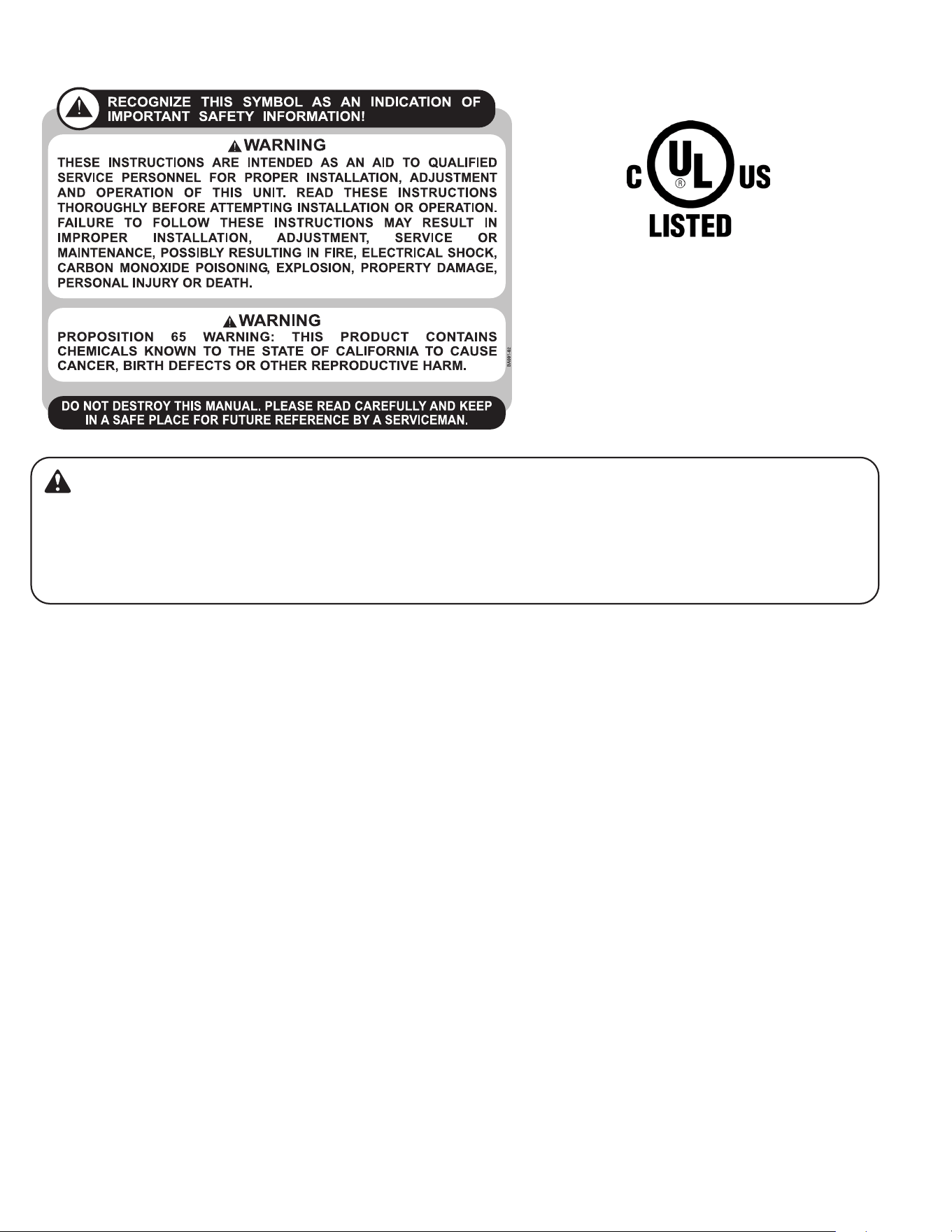
WARNING: This symbol indicates the possibility of a
hazard to personnel.
CAUTION: This symbol indicates the possibility of
property damage or serious consequences.
WARNING:
1. Installation must be performed according to the installation
instructions. Improper installation can cause water leakage, electrical
shock, or fire.
2. Use only the included accessories and parts, and specified tools for
the installation. Using nonstandard parts can cause water leakage,
electrical shock, fire, and injury or property damage.
3. Make sure that the outlet you are using is grounded and has the
appropriate voltage. The power cord is equipped with a three-prong
grounding plug to protect against shock. Voltage information can be
found on the nameplate of the appliance.
4. Your appliance must be used in a properly grounded wall
receptacle. If the wall receptacle you intend to use is not adequately
grounded or protected by a time delay fuse or circuit breaker (the
fuse or circuit breaker needed is determined by the maximum current
of the appliance. The maximum current is indicated on the model
nameplate located on the appliance, have a qualified electrician install
the proper receptacle.
5. Install the appliance on a flat, sturdy surface. Failure to do so could
result in damage or excessive noise and vibration.
6. The appliance must be kept free from obstruction to ensure proper
function and to mitigate safety hazards.
7. The unit should not be in contact with any equipment that will
transmit vibration to the unit. Any excessive vibration or pulsation to
the unit could result in damage to the refrigerant tubing.
8. Do not modify the length of the power cord or use an extension
cord to power the appliance.
9. Do not share a single outlet with other electrical appliances.
Improper power supply can cause fire or electrical shock.
10. Do not install your air conditioner in a wet room such as a
bathroom or laundry room. Too much exposure to water can cause
electrical components to short circuit.
11. Do not install the appliance in a location that may be exposed to
combustible gas, as this could cause fire.
12. Do not operate the appliance if it has been dropped or damaged.
13. Do not touch the appliance with wet or damp hands or when
barefoot.
14. If the air conditioner is knocked over during use, turn off the
appliance and unplug it from the main power supply immediately.
Visually inspect the appliance to ensure there is no damage. If you
suspect the appliance has been damaged, contact a technician or
customer service for assistance.
15. In a thunderstorm, the power must be cut off to avoid damage
to the machine due to lightning. Your air conditioner should be used
in such a way that it is protected from moisture. e.g. condensation,
splashed water, etc. Do not place or store your air conditioner
where it can fall or be pulled into water or any other liquid. Unplug
immediately if it occurs.
16. All wiring must be performed strictly in accordance with the
wiring diagram located inside of the appliance.
17. The appliance’s circuit board(PCB) is designed with a fuse to
provide over-current protection. The specifications of the fuse are
printed on the circuit board, such as: T 3.15A/250V, etc.
18. After proper installation, condensate will not overflow during
normal use. If the fan hits the built-up water and the sound annoys
you, please remove the cap located at the back of the air conditioner
to drain the water away.
CAUTION:
1. This appliance is not intended for use by persons (including
children) with reduced physical, sensory or mental capabilities or
lack of experience and knowledge, unless they have been given
supervision or instruction concerning use of the appliance by a person
responsible for their safety. Children should be supervised to ensure
that they do not play with the appliance. Children must be supervised
around the appliance at all times.
2. If the supply cord is damaged, it must be replaced by the
manufacturer, its service agent or similarly qualified persons in order
to avoid a hazard.
3. Prior to cleaning or other maintenance, the appliance must be
disconnected from the supply mains.
4. Never use this appliance if it is not working properly, or if it has
been dropped or damaged.
5. Do not run cord under carpeting. Do not cover cord with throw rugs,
runners, or similar coverings. Do not route cord under furniture or
appliances. Arrange cord away from traffic area and where it will not
be tripped over.
6. Do not operate with a damaged cord, plug, power fuse or circuit
breaker. Discard the appliance or return to an authorized service
facility for examination and/or repair.
7. To reduce the risk of fire or electric shock, do not use this fan with
any solid-state speed control device.
8. The appliance shall be installed in accordance with national wiring
regulations.
9. Contact the authorized service technician for repair or maintenance
of this appliance.
10. Contact the authorized installer for installation of this appliance.
11. Do not cover or obstruct the inlet or outlet grilles.
12. Do not use this product for functions other than those described in
this instruction manual.
13. Before cleaning, turn off the power and unplug the appliance.
14 .Disconnect the power if strange sounds, smell, or smoke comes
from it.
15. Do not press the buttons on the control panel with anything other
than your fingers.
16. Do not operate or stop the appliance by inserting or pulling out the
power cord plug.
17. Do not use hazardous chemicals to clean or come into contact with
the appliance.
18. Do not use the appliance in the presence of flammable substances
or vapor such as alcohol, insecticides, petrol,etc.
19. Always contact a qualified person to carry out repairs. If the power
supply cord is damaged, it must be replaced with a new power supply
cord obtained from the product manufacturer and not repaired.
20. Hold the plug by the head of the power plug when taking it out.
21. Turn off the product when not in use.

5
A. IMPORTANT SAFETY AND GENERAL INFORMATION
A.3 Warning For Using R32 Refrigerant
For R32 refrigerant models:
1. Appliance shall be installed, operated and stored in a room with a floor
area larger than 43 sq ft.
2. Appliance shall not be installed in an unventilated space, if that space is
smaller than 43 sq ft.
3. Compliance with national gas regulations shall be observed.
4. Keep ventilation openings clear of obstruction.
5. The appliance shall be stored so as to prevent mechanical damage from
occurring.
6. A warning that the appliance shall be stored in a well-ventilated area
where the room size corresponds to the room area as specified for
operation.
7. Any person who is involved with working on or opening a refrigerant
system must be certified for refrigerant handling as required by local,
state, and federal regulations.
8. Servicing shall only be performed as recommended by the equipment
manufacturer. Maintenance and repair requiring the assistance of other
skilled personnel shall be carried out under the supervision of the person
competent in the use of flammable refrigerants.
9. Please follow the instruction carefully to handle, install, clear, and
service the air conditioner to avoid any damage or hazard. Flammable
Refrigerant R32 is used within air conditioner. When maintaining or
disposing the air conditioner, the refrigerant (R32) shall be recovered
properly, and shall not be discharged to air directly.
10. No any open fire or device like a switch which may generate spark/
arcing shall be around the air conditioner to avoid causing ignition of the
flammable refrigerant used.
11. Please follow the instruction carefully to store or maintain the air
conditioner to prevent mechanical damage from occurring.
12. Flammable refrigerant R32 is used in air conditioner. Please follow the
instruction carefully to avoid any hazard.
13. For specific information on the type of gas and the amount of
refrigerant used, refer to the model nameplate on the unit.
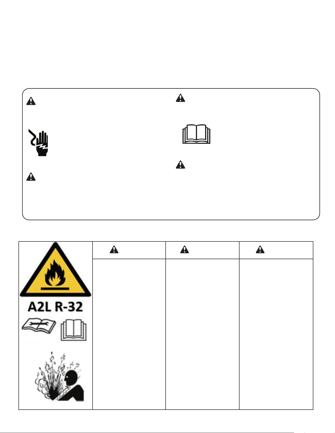
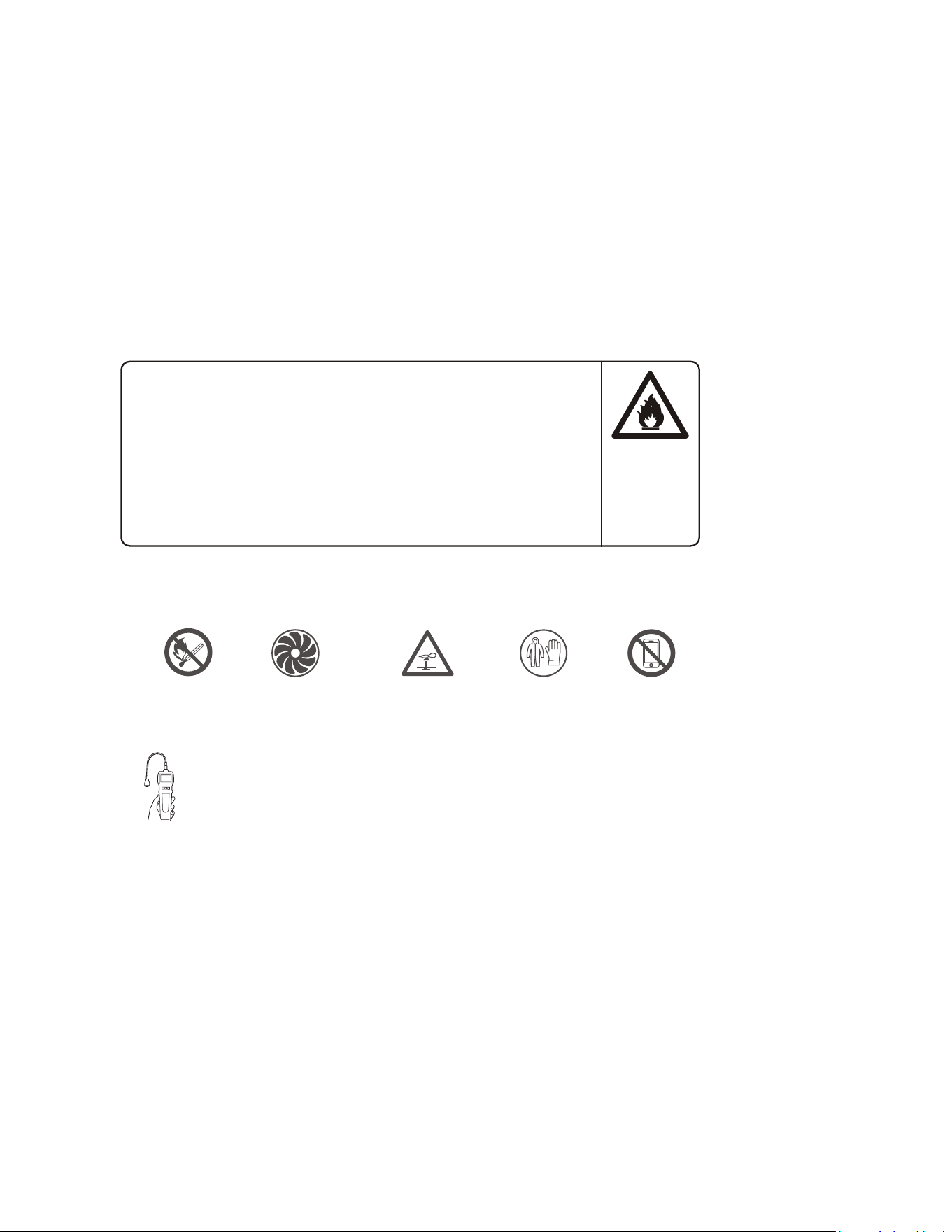
CAUTION: Risk of fire/flammable materials
(Required for R32 units only)
WARNING: low burning velocity material
(For R32 models apply to IEC60335-2-40:2018)
Note about Fluorinated Gases
1. Fluorinated greenhouse gases are contained in hermetically sealed
equipment. For specific information on the type, the amount and the Co2
equivalent in tonnes of the fluorinated greenhouse gas(on some models),
please refer to the relevant label on the unit itself.
2. Installation, service, maintenance and repair of this unit must be
performed by a certified technician.
3. Product De-commissioning and recycling must be performed by a
certified technician.
For Household Use Only Read And Save These Instructions
1. Transport of equipment containing flammable refrigerants:
See transport regulations.
2. Marking of equipment using signs:
See local regulations.
3. Disposal of equipment using flammable refrigerants:
See national regulations.
4. Storage of equipment/appliances:
The storage of equipment should be in accordance with the manufacturer’s
instructions.
5. Storage of packed (unsold) equipment:
Storage package protection should be constructed such that mechanical
damage to the equipment inside the package will not cause a leak of
the refrigerant charge. The maximum number of pieces of equipment
permitted to be stored together will be determined by local regulations.
6. Information on servicing:
1) Checks to the area:
Prior to beginning work on systems containing flammable refrigerants,
safety checks are necessary to ensure that the risk of ignition is minimized.
For repair to the refrigerating system, the following precautions shall be
complied with prior to conducting work on the system.
2) Work procedure:
Work shall be undertaken under a controlled procedure so as to minimize
the risk of a flammable gas or vapor being present while the work is being
performed.
3) General work area:
All maintenance staff and others working in the local area shall be
instructed on the nature of work being carried out. Work in confined spaces
shall be avoided. The area around the workspace shall be sectioned off.
Ensure that the conditions within the area have been made safe by control
of flammable material.
4) Checking for presence of refrigerant:
The area shall be checked with an appropriate refrigerant detector prior to
and during work, to ensure the technician is aware of potentially flammable
atmospheres. Ensure that the leak detection equipment being used is
suitable for use with flammable refrigerants, i.e. non-sparking, adequately
sealed or intrinsically safe.
5) Presence of fire extinguisher:
If any hot work is to be conducted on the refrigeration equipment or
any associated parts, appropriate fire extinguishing equipment shall be
available to hand. Have a dry powder or CO2 fire extinguisher adjacent to
the charging area.
6) No ignition sources:
No person carrying out work in relation to a refrigeration system which
involves exposing any pipe work that contains or has contained flammable
refrigerant shall use any sources of ignition in such a manner that it may
lead to the risk of fire or explosion. All possible ignition sources, including
cigarette smoking, should be kept sufficiently far away from the site of
installation, repairing, removing and disposal, during which flammable
refrigerant can possibly be released to the surrounding space. Prior
to work taking place, the area around the equipment is to be surveyed
to make sure that there are no flammable hazards or ignition risks. No
Smoking signs shall be displayed.
7) Ventilated area:
Ensure that the area is in the open or that it is adequately ventilated
before breaking into the system or conducting any hot work. A degree
of ventilation shall continue during the period that the work is carried
out. The ventilation should safely disperse any released refrigerant and
preferably expel it externally into the atmosphere.
8) Checks to the refrigeration equipment:
Where electrical components are being changed, they shall be fit for the
purpose and to the correct specification. At all times the manufacturer’s
maintenance and service guidelines shall be followed. If in doubt consult
the manufacturer’s technical department for assistance. The following
checks shall be applied to installations using flammable refrigerants:
a. The charge size is in accordance with the room size within which the
refrigerant containing parts are installed;
b. The ventilation machinery and outlets are operating adequately and are
not obstructed;
c. If an indirect refrigerating circuit is being used, the secondary circuit
shall be checked for the presence of refrigerant; Marking to the equipment
continues to be visible and legible. Markings and signs that are illegible
shall be corrected;
d. Refrigeration pipe or components are installed in a position where they
are unlikely to be exposed to any substance which may corrode refrigerant
containing components, unless the components are constructed of
materials which are inherently resistant to being corroded or are suitably
protected against being so corroded.
9) Checks to electrical devices:
Repair and maintenance to electrical components shall include initial
safety checks and component inspection procedures. If a fault exists that
could compromise safety, then no electrical supply shall be connected to
the circuit until it is satisfactorily dealt with. If the fault cannot be corrected
immediately but it is necessary to continue operation, an adequate
temporary solution shall be used. This shall be reported to the owner of
the equipment so all parties are advised. Initial safety checks shall include:
a. That capacitors are discharged: this shall be done in a safe manner to
avoid possibility of sparking;
b. That there no live electrical components and wiring are exposed while
charging, recovering or purging the system;
c. That there is continuity of earth bonding.

6
7. Repair to intrinsically safe components:
Do not apply any permanent inductive or capacitance loads to the circuit
without ensuring that this will not exceed the permissible voltage and
current permitted for the equipment in use. Intrinsically safe components
are the only types that can be worked on while live in the presence of a
flammable atmosphere. The test apparatus shall be at the correct rating.
Replace components only with parts specified by the manufacturer. Other
parts may result in the ignition of refrigerant in the atmosphere from a
leak.
8. Cabling:
Check that cabling will not be subject to wear, corrosion, excessive
pressure, vibration, sharp edges or any other adverse environmental
effects. The check shall also take into account the effects of aging or
continual vibration from sources such as compressors or fans.
9. Detection of flammable refrigerants
Under no circumstances shall potential sources of ignition be used in the
searching for or detection of refrigerant leaks. A halide torch (or any other
detector using a naked flame) shall not be used.
10. Leak detection methods:
The following leak detection methods are deemed acceptable for systems
containing flammable refrigerants. Electronic leak detectors shall be used
to detect flammable refrigerants, but the sensitivity may not be adequate,
or may need re-calibration. (Detection equipment shall be calibrated in a
refrigerant-free area.) Ensure that the detector is not a potential source of
ignition and is suitable for the refrigerant used. Leak detection equipment
shall be set at a percentage of the LFL of the refrigerant and shall be
calibrated to the refrigerant employed and the appropriate percentage of
gas (25 % maximum) is confirmed. Leak detection fluids are suitable for
use with most refrigerants but the use of detergents containing chlorine
shall be avoided as the chlorine may react with the refrigerant and corrode
the copper pipe-work. If a leak is suspected, all naked flames shall be
removed/extinguished. If a leakage of refrigerant is found which requires
brazing, all of the refrigerant shall be recovered from the system, or
isolated (by means of shut off valves) in a part of the system remote from
the leak. Oxygen free nitrogen (OFN) shall then be purged through the
system both before and during the brazing process.
11. Removal and evacuation
When breaking into the refrigerant circuit to make repairs or for any other
purpose conventional procedures shall be used. However, it is important
that best practice is followed since flammability is a consideration. The
following procedure shall be adhered to: Remove refrigerant; Purge the
circuit with inert gas; Evacuate; Purge again with inert gas; Open the
circuit by cutting or brazing. The refrigerant charge shall be recovered into
the correct recovery cylinders. The system shall be flushed with OFN to
render the unit safe. This process may need to be repeated several times.
Compressed air or oxygen shall not be used for this task. Flushing shall be
achieved by breaking the vacuum in the system with OFN and continuing
to fill until the working pressure is achieved, then venting to atmosphere,
and finally pulling down to a vacuum. This process shall be repeated until
no refrigerant is within the system. When the final OFN charge is used, the
system shall be vented down to atmospheric pressure to enable work to
take place. This operation is absolutely vital if brazing operations on the
pipe-work are to take place. Ensure that the outlet for the vacuum pump is
not close to any ignition sources and there is ventilation available.
12. Charging procedures:
In addition to conventional charging procedures, the following
requirements shall be followed. Ensure that contamination of different
refrigerants does not occur when using charging equipment. Hoses or
lines shall be as short as possible to minimize the amount of refrigerant
contained in them. Cylinders shall be kept upright. Ensure that the
refrigeration system is earthed prior to charging the system with
refrigerant. Label the system when charging is complete (if not already).
Extreme care shall be taken not to overfill the refrigeration system. Prior
to recharging the system it shall be pressure tested with OFN. The system
shall be leak tested on completion of charging but prior to commissioning.
A follow up leak test shall be carried out prior to leaving the site.
13. Decommissioning:
Before carrying out this procedure, it is essential that the technician
is completely familiar with the equipment and all its detail. It is
recommended good practice that all refrigerants are recovered safely.
Prior to the task being carried out, an oil and refrigerant sample shall be
taken in case analysis is required prior to re-use of reclaimed refrigerant.
It is essential that electrical power is available before the task is
commenced.
a. Become familiar with the equipment and its operation.
b. Isolate system electrically.
c. Before attempting the procedure ensure that: Mechanical handling
equipment is available, if required, for handling refrigerant cylinders;
All personal protective equipment is available and being used correctly;
The recovery process is supervised at all times by a competent person;
Recovery equipment and cylinders conform to the appropriate standards.
d. Pump down refrigerant system, if possible.
e. If a vacuum is not possible, make a manifold so that refrigerant can be
removed from various parts of the system.
f. Make sure that cylinder is situated on the scales before recovery takes
place.
g. Start the recovery machine and operate in accordance with
manufacturer’s instructions.
h. Do not overfill cylinders. (No more than 80 % volume liquid charge).
i. Do not exceed the maximum working pressure of the cylinder, even
temporarily.
j. When the cylinders have been filled correctly and the process completed,
make sure that the cylinders and the equipment are removed from site
promptly and all isolation valves on the equipment are closed off.
k. Recovered refrigerant shall not be charged into another refrigeration
system unless it has been cleaned and checked.
14. Labeling:
Equipment shall be labeled stating that it has been de-commissioned
and emptied of refrigerant. The label shall be dated and signed. Ensure
that there are labels on the equipment stating the equipment contains
flammable refrigerant.
15. Recovery:
When removing refrigerant from a system, either for servicing or
decommissioning, it is recommended good practice that all refrigerants
are removed safely. When transferring refrigerant into cylinders, ensure
that only appropriate refrigerant recovery cylinders are employed. Ensure
that the correct number of cylinders for holding the total system charge
is available. All cylinders to be used are designated for the recovered
refrigerant and labeled for that refrigerant (i.e. special cylinders for the
recovery of refrigerant).
Cylinders shall be complete with pressure relief valve and associated shut-
off valves in good working order. Empty recovery cylinders are evacuated
and, if possible, cooled before recovery occurs. The recovery equipment
shall be in good working order with a set of instructions concerning
the equipment that is at hand and shall be suitable for the recovery of
flammable refrigerants. In addition, a set of calibrated weighing scales
shall be available and in good working order. Hoses shall be complete
with leak-free disconnect couplings and in good condition. Before using
the recovery machine, check that it is in satisfactory working order, has
been properly maintained and that any associated electrical components
are sealed to prevent ignition in the event of a refrigerant release. Consult
manufacturer if in doubt. The recovered refrigerant shall be returned to
the refrigerant supplier in the correct recovery cylinder, and the relevant
Waste Transfer Note arranged. Do not mix refrigerants in recovery units
and especially not in cylinders. If compressors or compressor oils are to
be removed, ensure that they have been evacuated to an acceptable level
to make certain that flammable refrigerant does not remain within the
lubricant. The evacuation process shall be carried out prior to returning
the compressor to the suppliers. Only electric heating to the compressor
body shall be employed to accelerate this process. When oil is drained
from a system, it shall be carried out safely.
NOTE: Check the appliance regularly and refer to TROUBLESHOOTING or
contact our customer support if it shows any of the following signs:
- Power cord or plug is damaged.
- Loud noise, unusual smell or excessive heat.
A. IMPORTANT SAFETY AND GENERAL INFORMATION
7
A. IMPORTANT SAFETY AND GENERAL INFORMATION
A.4 Importance of a Quality Installation
Optimal system performance and longevity depend upon a quality and proper installation. Failure to properly install this unit could result in
undesirable operation and subsequent faults and potential failures.
Carefully follow all guidelines listed in the manual and industry best practices. Conform to all local code requirements. Contact your local
technical representative with any questions or concerns.
A.5 Product Inspection
Upon receiving the unit, inspect it for any damage from shipment. Claims for damage, either shipping or concealed, should be filed
immediately with the shipping company. IMPORTANT: Check the unit model number, Cooling size, electrical characteristics, and accessories
to determine if they are correct.
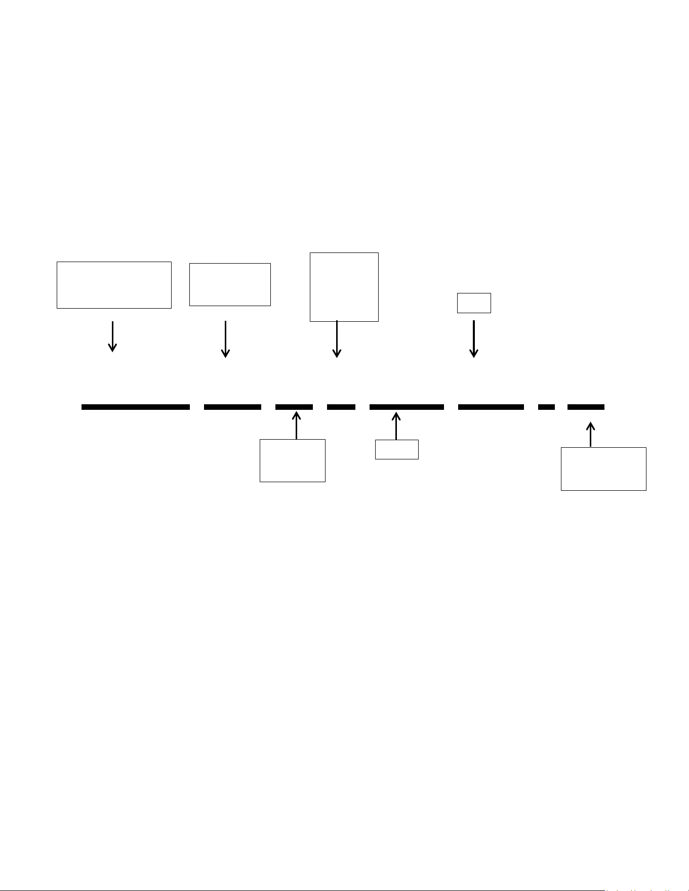
A.5 Model Identification Guide
Figure A.5 (Model Identification Guide)
A.6 Unit Features
This Premium unit has many exciting features which are different than those found on standard PTAC models. The owner must be
familiar with these features in order to fully understand the operation and capability of the unit.
Intelligence–Your Premium unit has an on board computer that utilizes real time diagnostics to prolong the life of your unit. There is
an LED indicator on the control board, behind the front panel, that will flash an error code if the unit has detected some kind of fault condition.
In many cases, the unit will automatically clear the fault condition and continue operating with no interruption. In some cases, the condition
cannot be cleared and the unit will require service. In those cases, an“Fx” failure mode will be displayed on the digital display. For a detailed
list of all error codes and “Fx” conditions, see section M.2, 6-Status LED Indicator Definitions for further details.
Memory–Your Premium unit also has memory. If power is lost, all of the control settings (set point, mode, fan speed, on/off and
configuration) are remembered. So when power is restored, the unit will start back up in the mode (and configuration) it was in, when power
was lost.
Premium Sound-The unit has 2 fan motors. The outdoor fan motor will run at minimum speed for 10 seconds before the compressor
start to reduce any compressor starting noise.
Random Compressor Restart-To help prevent power surges after a power outage (from many of your PTACS starting at the same
time), the compressor is equipped with a 2:45 to 3:15 random restart delay feature. Whenever the unit is plugged in, or power has been
restarted, a random compressor restart will occur.
Compressor Protection-To prevent short cycling of the compressor and maximize it’s life, there is a random start-up delay of 3
minutes on the compressor and a minimum compressor run time of 3 minutes.
THE EXPERTS IN ROOM AIR CONDITIONING
2023 PTAC Component Model Number Reference Guide
PDH 09 K 3 SG R3 - A
P: PTAC
D: Digital
H/E: HP or Cool only
Approximate
Cooling
BTU/HR
Voltage
K: 230/208
R: 265V
Minor
Engineering
Revision
Heater Size:
3: 3.5 Kw
5: 5Kw
Hidden Character
Series
R32
2023 Gree R32 Model # based on SG chassis
2: 2.5 Kw

8
A. IMPORTANT SAFETY AND GENERAL INFORMATION
Automatic Room Freeze Protection–automatically keeps the temperature in the room from getting too cold, where water pipes might
freeze. If the unit is configured for the freeze protection feature to be active (which is the default condition), then whenever power is supplied to
the unit, and the unit senses the temperature is below 40°F, the fan motor and electric heater are turned on, and will warm the room to 50°F.If
Freeze protection is not required, change the configuration switch to turn the feature off (see section J.3 Dip switches on unit configuration).
Automatic defrost protection –When the outdoor temperature gets too cold (approx. 28°F) and the unit can no longer effectively
heat with the compressor, the unit will automatically switch to electric heating. The unit will then heat with electric heat until the outside
temperature rises enough (approx.40°F), so the compressor can be used again.
Automatic Quick Warmup (for heat pump models only)-If the room temperature falls to 5°F below the set point temperature, the
reverse cycle heat is shut off and the electric strip heat is turned on for one cycle, until heating is satisfied.
LED Indicator’s and Buttons The touch pad has buttons for POWER, UP, DOWN, COOL, HEAT, CONSTANT FAN, HIGH, LOW and AUTO.
It also has LEDs that correspond to the mode, fan speed and set point operation, to indicate the unit’s status. The LEDs above the CONSTANT
FAN, COOL, and HEAT mode buttons indicate what operating mode is active. The LEDs above the LOW, AUTO, and HIGH buttons indicate the fan
speed that is selected. The LED above the power button is the unit On/Off status LED. If the unit is in ON mode, the LED will be blue. If the unit is
OFF, the LED will go out.
Configure Fan to Optimize Selected Application Unit can be optimized to selected application by configuring the fan to run in
continuous mode or cycle on and off with the compressor and electric heater. In cycle mode, fan will continue to run for a while after
compressor or electric heater stops in order blow off any residual heat or cool left on coil.
Unit Configuration There are many different configuration possibilities, through both dip switches and the digital keypad, that allow
you to configure the unit for your exact application. See section J.3 on unit configuration for more details. Following are the configuration
selections that have not previously been mentioned:
Temperature Display The unit can display in either °For °C
Indoor Temperature Sensor Biasing Optimize the room temperature sensor reading to your exact application (one for cooling and an
other for heating).
Emergency Heat (for Heat Pump Only) Disable the compressor during heating mode operation (heat only with Electric Heat).
Display Set point or Room Temperature The unit can be configured to display the room temperature or set point only, during heating
and cooling modes. See section J.3 on unit configuration for more details.
Limit the Set point Range The unit can be configured to limit the controlling set point range. The display will always show the
complete set point range, but the controlling set point will be limited to the configured minimum and maximum set point selected. See section
J.3 on unit configuration for more details.
Energy Management (Sometimes known as Front Desk Control) an input is provided so that the unit can be manually disabled from a
different location. If the unit detects 24vac on this input, it will automatically turn itself off. If no voltage is detected on the input, the unit will run
normally.
Wall Thermostat Control A wired wall thermostat can be connected to the unit. If it is, the unit must be configured to disable the
keypad. See section J.3 on wired inputs and unit configuration for more details.
9
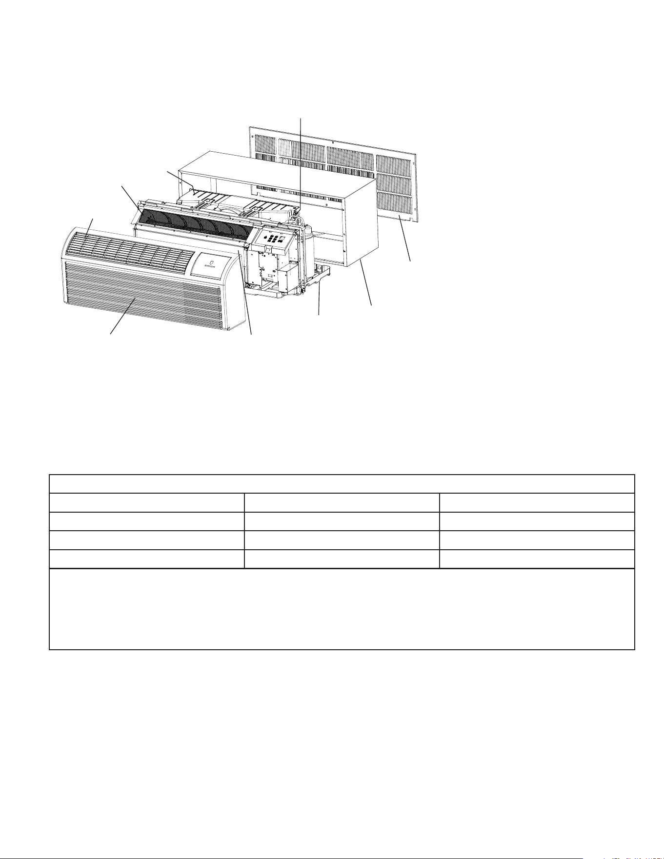
B. SPECIFICATIONS
B.1 Major Components and Dimensions
Discharge
grille
Wire screen
Outdoor
orifice
sheets
Coil tube
Accessory
outdoor
grille
Accessory
wall
sleeve
Basepan
Indoor
coil
Front
panel
PDXWS Wall Sleeve Dimensions
16” H x 42” x W x 13 ” D
Front Cover Dimensions
16” H x 42” x W x 7 ” D
Cut-out Dimensions
16 x 42
3/4
3/4
1/4
1/4
Figure B.1 (Major Components and Dimensions)
B.2 Product Data Information
Operation Environment
Operating Temperature Range
Indoor side DB/WB (°F) Outdoor side DB/WB (°F)
Maximum cooling 80/67 115/75
Maximum RC Heating 80/ - 75/65
Maximum Electric Heating 77/ - 77/ -
Ambient temperature range(indoor temperature)for cooling is 64-80°F,
Ambient temperature range(indoor temperature)for heat pump is 57-80°F,
Ambient temperature range(outdoor temperature)for cooling is 64-115°F
Ambient temperature range(outdoor temperature) for heat pump is 39-75°F,
Ambient temperature range(outdoor temperature)for Electric Heating is 19-77°F.
10
C. INSTALLATION OF THE UNIT
C.1 Pre-Installation Checkpoints
C.1.1 Before attempting any installation, carefully consider the following points:
Before attempting any installation, carefully consider the following points:
• Inspect all components and accessories for damage before and after installation.
• Remove the cardboard wall sleeve support and grill weatherboard.
• Check for proper wall sleeve installation in accordance with the wall sleeve installation instructions.
• Check for a sub-base kit or other means of structural support which is required for ALL installations projecting more than 8” into room.
• Install the recommended Condensate Drain Kits for complete condensate removal.
• Ensure that the chassis is installed in a 16” high x 42” wide wall sleeve that is no deeper than 13 ¾”. A baffle kit is required if the sleeve
exceeds that depth.
• Ensure that chassis and chassis front cover are installed and secured properly.
• Ensure that drapes, bed, bedspread, furniture, etc. DO NOT block either return or discharge air grilles.
• Inspect the condenser air inlet and outlet for any obstructions (shrubbery, etc.)
• Ensure that ‘reset’ button is pressed on LCD device (only on 230V models)
•
C.1.2 Important Considerations
C.1.3 Introduction to R32 Refrigerants
C.1.4 Additional Notes:
• The installation site should be in a well-ventilated condition.
• The sites for installing and maintaining an air conditioner using Refrigerant R32 should be free from open fire or welding, smoking, drying
oven or any other heat source higher than 1000˚F which easily produces open fire.
• When installing an air conditioner, it is necessary to take appropriate anti-static measures such as wear anti-static clothing and/or gloves.
• It is necessary to choose the site convenient for installation or maintenance wherein the air inlets and outlets of the indoor and outdoor
units should be not surrounded by obstacles or close to any heat source or combustible and/or explosive environment.
• If the indoor unit suffers refrigerant leak during the installation, all the personnel should go out till the refrigerant leaks completely for 15
minutes. If the product is damaged, it is a must to carry such damaged product back to the maintenance station and it is prohibited to weld
the refrigerant pipe or conduct other operations on the user’s site.
• It is necessary to choose the place where the inlet and outlet air of the indoor unit is even.
ASSEMBLING YOUR AIR CONDITIONER
17
Installation & Assembly Instructions
Important Considerations
1. Before installing the appliance, you must read the manual carefully to
get the safety informa�on and notes.
2. Unit refrigerant charge amount: refer to unit name plate marking.
3. A leak test must be done a�er the installa�on is completed.
4. It is a must to do the safety inspec�on before maintaining or repairing
an air condi�oner using combus�ble refrigerant in order to ensure
that the fire risk is reduced to minimum.
5. It is necessary to operate the machine under a controlled procedure
in order to ensure that any risk arising from the combus�ble gas or
vapor during the opera�on is reduced to minimum.
Introduction to Refrigerants R32
1.Site Safety 2.Operation Safety
3.Installation Safety
- Refrigerant Leak Detector
- Appropriate Installa�on Loca�on
- The le� picture is the schema�c diagram of a refrigerant leak detector.
Please note that:
1. The installa�on site should be in a well-ven�lated condi�on.
2. The sites for installing and maintaining an air condi�oner using Refrigerant R32 should be
free from open fire or welding, smoking, drying oven or any other heat source higher than
548 which easily produces open fire.
3. When installing an air condi�oner, it is necessary to take appropriate an�-sta�c measures
such as wear an�-sta�c clothing and/or gloves.
4. It is necessary to choose the site convenient for installa�on or maintenance wherein the air
inlets and outlets of the indoor and outdoor units should be not surrounded by obstacles
or close to any heat source or combus�ble and/or explosive environment.
5. If the indoor unit suffers refrigerant leak during the installa�on, all the personnel should go
out �ll the refrigerant leaks completely for 15 minutes. If the product is damaged, it is a
must to carry such damaged product back to the maintenance sta�on and it is
prohibited to
weld the refrigerant pipe or conduct other opera�ons on the user's site.
6. It is necessary to choose the place where the inlet and outlet air of the indoor unit is even.
7. It is necessary to avoid the places where there are other electrical products, power switch
plugs and sockets, kitchen cabinet, bed, sofa and other valuables right under the lines on
two sides of the indoor unit, and also prevent mechanical damage from occurring.
Open Flames
Prohibited
Ven�la�on
Necessary
Mind Sta�c
Electricity
Must Wear
Protec�ve Clothing
and An�-Sta�c
Gloves
Don't Use
Mobile Phone
11
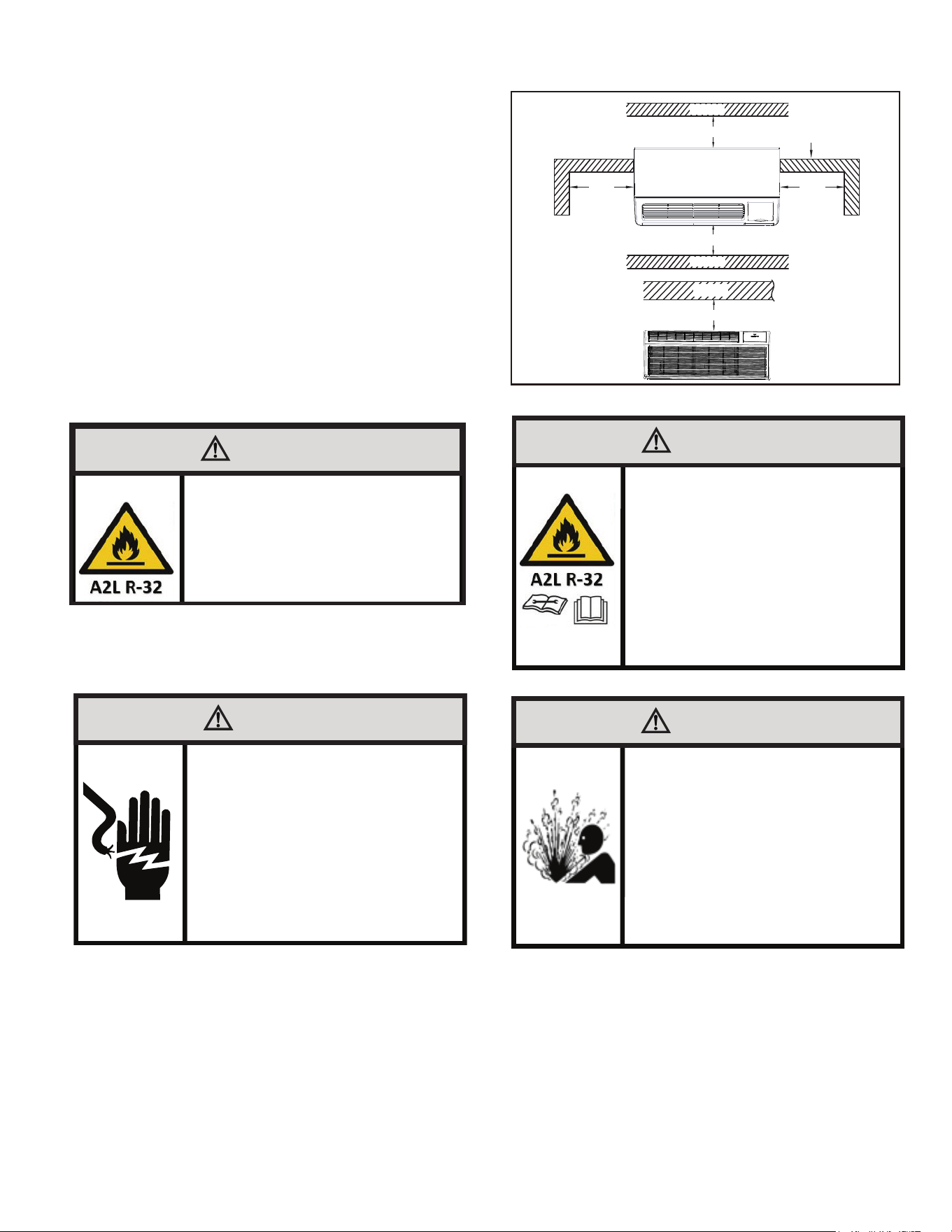
C.3 Choosing a Location
Installation Clearances
Improper installation of the Air Conditioner can cause poor
performance and premature wear of the unit.
Ensure that the PTAC unit is installed with proper clearances as
shown if figure C.3. The distance between the air conditioner 1 foot
and the around obstacles should meet the requirement as below:
over 3.5 feet (upper side), over 2 inches (left side), over 2 inches
(right side), over 3 feet (front side) and over 3 feet (rear side).
Ensure plug is accessible and no obstructions or enclosures are
within clearances limits to allow for proper airflow.
Ensure no open flames, or surfaces that will exceed 1000 degrees
Fahrenheit are within 5 feet of the unit.
Observe all warnings in this manual when choosing a location for
your air conditioner.
WARNING
Refigeration System
Under High Pressure
Do not puncture, heat, expose to flame or
incinerate.
Only certified refrigeration technicians should
service this equipment.
R410A and R32 systems operate at higher
pressures than R22 equipment.
Appropriate safe service and handling
practices must be used.
Only use gauge sets designed for use with
R410A or R32.
Do not use standard R22 gauge sets..
WARNING
Fire Hazard
A2L refrigerant is classified as mildly
flammable. Do not install unit next to open
flame sources, or surfaces that will exceed
1200 degrees fahrenheit.
WARNING
Electrical Shock Hazard
Make sure your electrical receptacle has the
same configuration as your air conditioner’s
plug. If different, consult a Licensed Electrician.
Do not use plug adapters.
Do not use an extension cord.
Do not remove ground prong.
Always plug into a grounded 3 prong outlet.
Failure to follow these instructions can result in
death, fire, or electrical shock.
WARNING
Do not use means to accelerate the defrosting
process or to clean, other than those
recommended by the manufacturer.
The appliance shall be stored in a room without
continuously operating ignition sources.
(for example; open flames, an operating gas
appliance, or an operating electric heater).
Do Not Pierce or Burn
Be aware that refrigerants may not contain
an odor
Front View
Ceiling
over 3.5 ft.
WALL
Top View
over
2 in.
over 3 ft.
over 3 ft.
over
2 in.
Outside wall
WALL
WALL
Figure C.3.1 (Clearance Limits)
C. INSTALLATION OF THE UNIT
12
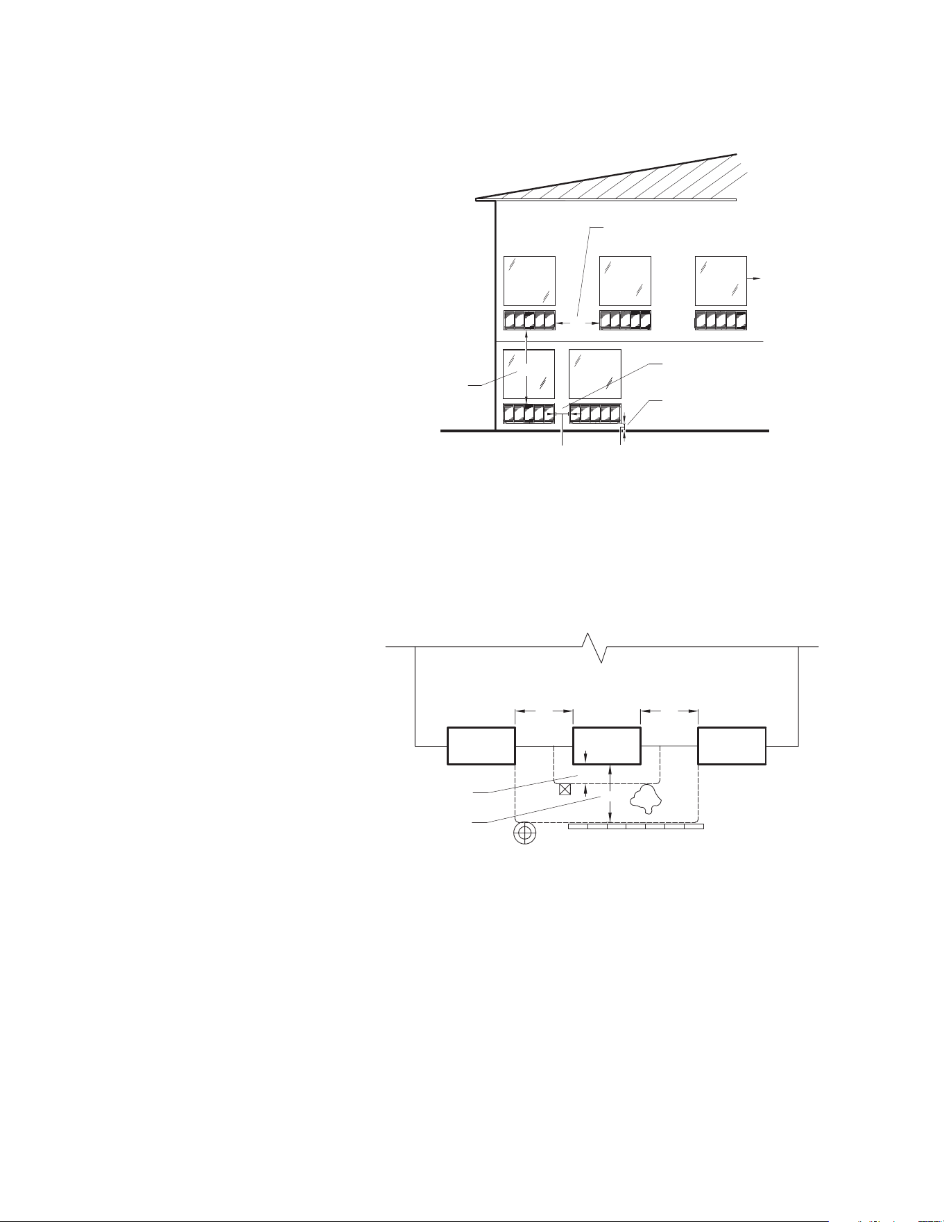
C. INSTALLATION OF THE UNIT
C.3 Installation Clearances (Continued)
For proper PTAC unit performance and maximum operating life refer to the minimum installation clearances below:
Figure C.3.2 (Installation Clearances)
For PTACs on the ground floor or anytime obstructions are present, use the following guidelines:
The above suggestions are for reference only and do not represent all possible installations. Please contact Friedrich for information regard-
ing affects of other installation arrangements. By following these simple recommendations you can be confident that your Friedrich PTAC will
provide years of worry free operation.
THREE OR MORE PTACs
ADJACENT 36" MINIMUM
GROUND FLOOR PTACs
6" MINIMUM FROM GRADE
TWO ADJACENT PTACs
12" MINIMUM
TYPICAL
WINDOW
VIEW: OUTSIDE BUILDING ELEVATION
60" VERTICAL
MINIMUM
BETWEEN
PTACs
12"
6"
36"
60"
PTAC units should be installed
no closer than 12” apart when
two units are side by side.
If three or more PTAC units are
to operate next to one another
allow a minimum of 36” between
units. Also, a vertical clearance
of 60” should be maintained
between units installed. In the
interior of the room the unit
should be located a minimum of 1/4”
PTAC
SHRUB
POLE
FENCE OR WALL
CATPCATP
TYPICAL BUILDING ( PLAN VIEW )
CONDENSING UNIT
12"
36"
36"
36"
36" MINIMUM, MAJOR
OBSTRUCTIONS
12" MINIMUM, MINOR
OBSTRUCTIONS
Fo
r minor obstructions such as lamp
poles or small shrubber
y a clearance
of 12" from the outdoor louver should
be maintained
.
Fo
r major obstructions such as a solid
f
ence, wall or other heat rejecting
device like a condensing unit, a minimum
distance of 36" should be kept
.
Figure C.3.3 (Installation Clearances)
13
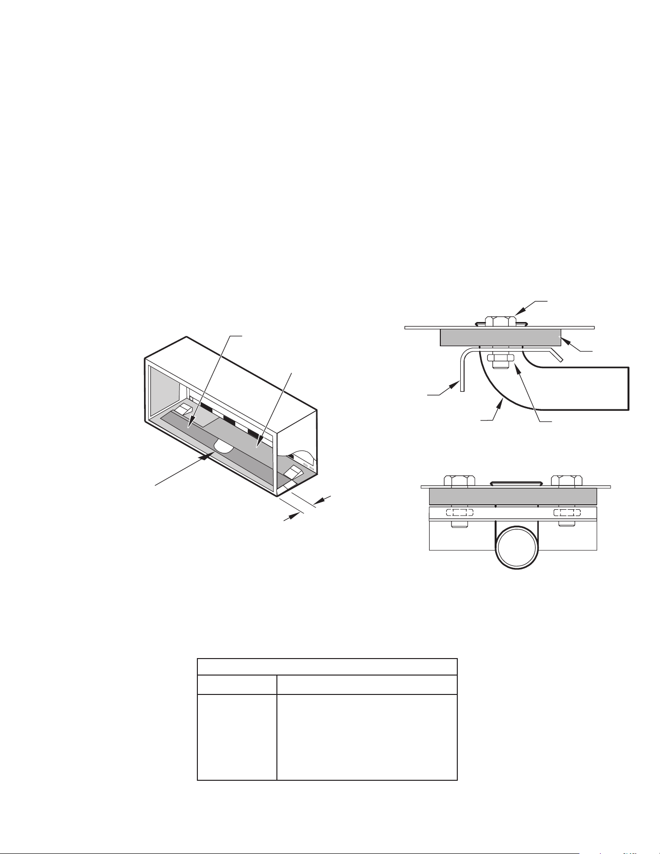
C. INSTALLATION OF THE UNIT
Figure C.4.1 (Internal Drain Kit)
PXDR10
QUANTITY DESCRIPTION
2
1
1
3
4
2
2
COVER PLATES
MOUNTING PLATE
DRAIN TUBE
MOUNTING PLATE GASKET
#10 X ½” SHEET METAL SCREWS
#10-24 X ½ ” MACH. SCREWS
#10-24 X ½" LOCK NUTS
C.4 Install Unit
C.4.1 Install Internal Drain Kit (If applicable)
1. The PXDR10 Drain Kit if applicable, must be installed before the
wall sleeve is installed into the wall.
NOTE: Determine whether drain will be located within the wall, on
the indoor side, or will drain to the exterior of the building. Follow
appropriate instructions below depending on your particular type of
installation.
Internal Drain
NOTE: If installing an internal drain, you MUST install a drain kit on
the wall sleeve before the wall sleeve is installed.
1. Locate the drain within the “Preferred” area of best drainage.
Maintain at least a ½” clearance from the embossed area.
2. Using the mounting plate with the ½” hole as a template, mark
and drill two, 3/16” mounting holes and a ½” drain hole in the sleeve
bottom.
3. Remove the backing from the gasket and mount it on the flat side of
the mounting plate. (See Figure C.4.2). Insert the drain tube through
the hole in the gasket and mounting plate so the tube flange will be
against the wall sleeve.
4. Position the assembly beneath the drilled holes and secure it with
#10-24 x ½” machine screws and lock nuts provided. Seal the tops of
the screws with silicone caulking.
5. Use ½” I.D. copper tube, PVC pipe, or vinyl hose (obtained locally)
to connect the internal drain tube to the drain system in the building.
6. Referring to C.4.2 locate and assemble the (2) two cover plates and
gaskets over the drain holes at the rear of the wall sleeve. Attach
them with the #10 sheet metal screws provided. Make certain that the
four overflow slots at the rear of the wall sleeve are not blocked (See
drawing of the back of the sleeve Figure C.4.2).
7. If a deep wall extension (PDXWSEXT) is used, after installing the
field supplied flashing, caulk as required. Be sure to caulk around the
flashing and the wall sleeve where the hole was drilled for the drain
tube.
DRAIN TUBE
SIDE VIEW
FRONT VIEW
WALL SLEEVE
OPTIONAL AREA
PREFERRED AREA-
NO FOAM INSULATION
NOTE: IF THE DRAIN MUST BE
LOCATED IN THE OPTIONAL
AREA, THE FOAM INSULATION
MUST BE CUT AWAY AND
REMOVED TO ALLOW ACCESS
TO THE DRAIN.
NUT
MOUNTING
PLATE
GASKET
SCREW
3"
OPTIONAL
AREA MUST BE 18”-21” CENTERED
FROM SIDEW
ALLS TO ENSURE DRAINAGE
14
C. INSTALLATION OF THE UNIT
C.4.2 External Drain Kit Installation
When using an external drain system, the condensate is removed
through either of two drain holes on the back of the wall sleeve. Select
the drain hole which best meets your drainage situation and install the
drain kit. Seal off the other with a cover plate.
Drain Tube Installation
1. Peel the backing tape off the gaskets and apply the sticky side
to one cover plate and one mounting plate as shown in Details
A and B.
2. Place the drain tube through the gasket and the mounting plate
with the flange toward the wall sleeve.
3. Attach the drain tube assembly to one of the two drain holes at
the rear of the wall sleeve. The large flange on the mounting
plate is positioned at the bottom of the sleeve facing toward the
sleeve, Detail B. When the drain tube is positioned at the desired
angle, tighten the screws.
Cover Plate Installation
4. Mount the foam gasket to the cover plate. Using two #10 x ½”
sheet metal screws (provided), attach the cover plate to the
remaining drain hole. Make certain the large flange on the plate
is positioned at the bottom of the sleeve.
5. Discard the additional cover plate, gasket, machine screws, and
lock nuts.
NOTICE
If the wall sleeve has not been installed, the drain tube
must be rotated to a horizontal position until after the
sleeve is installed. Tighten the mounting plate screws
when the tube is in the proper position. Make certain that
the four overflow slots at the rear of the wall sleeve are not
blocked (See Figure C.4.2).
When sealing the sleeve on the outside of the building, be
careful NOT to let the sealant block the two condensate
drain holes or the four overflow slots at the bottom flange
of the sleeve.
Potential property damage can occur if instructions are
not followed.
Figure C.4.2 (External Drain Kit Installation)
FOAM
GASKET
OVERFLOW
SLOTS
DETAIL B
DETAIL A
COVER
PLATE
FOAM
GASKET
SCREWS
½” O.D. TUBE
MOUNTING
PLATE
NUT
15
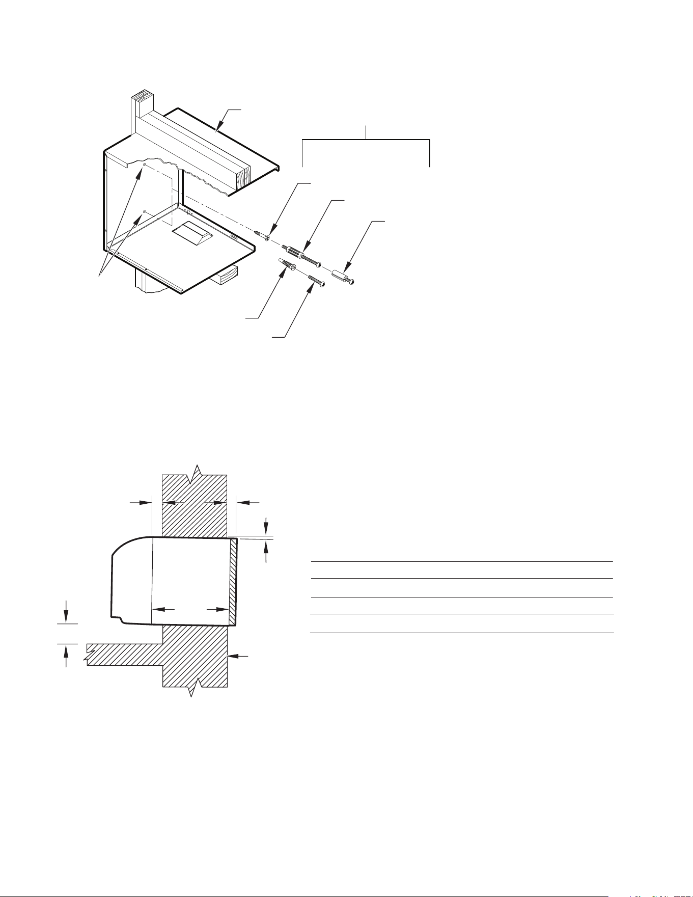
C. INSTALLATION OF THE UNIT
C.4.3 Wall Sleeve Installation Instructions (PDXWS)
NOTE: Insure that the unit is only installed in a wall structurally
adequate to support the unit including the sleeve, chassis and
accessories. If the sleeve projects more than 8” into the room, a
sub-base or other means of support MUST be used. Please read
these instructions completely before attempting installation.
The following instructions apply ONLY to walls less than 13 ¼” in
depth.
NOTE: If the wall is thicker than 13 1/4” a deep wall sleeve or wall
sleeve extension MUST be used. The deep wall sleeve may be
special ordered through your Sales Representative.
1. The PXDR10 Drain Kit (optional for new construction) see page
10 if applicable, must be installed before the wall sleeve is installed
into the wall.
2. From inside the building, position the wall sleeve in the opening
and push it into the wall until it protrudes at least ¼” on the out-
side. Do not allow sleeve to be pulled. (See Figure C.4.2).
3. Position the wall sleeve with a slight tilt towards the outside to
facilitate condensate drainage. It should be level side-to-side and
the front should be ¼ bubble higher than the back.
20
"
MAX.
16-¼
"
42-¼
"
MIN.
LINTEL TO SUPPORT
MASONRY WALLS
ELECTRICAL
RECEPTACLE
ELECTRICAL
RECEPTACLE
WALL OPENING
WALL SLEEVE
INSULATION
INSULATION
SMOOTH SIDE OF SCREW
CLIP FACING INTO ROOM
NOTE: All 230/208V units are manufactured with a 67” power cord and all 265V units with a 27 1/2” power cord.
60
"
MAX.
13-¾
"
WARNING
Falling Object Hazard
Not following Installation Instructions for
mounting your air conditioner can result
in property damage, injury, or death.
NOTICE
DO NOT allow any pitch toward the inside.
Flashing on all 4 sides of the opening is recommended.
Potential property damage can occur if instructions are
not followed.
Figure C.4.3.1 (Typical Wall Sleeve Installation)
16
C. INSTALLATION OF THE UNIT
C.4.3 Wall Sleeve Installation Instructions (PDXWS)(Cont)
OPTIONAL
SUBBASE
LEVELING SCREW
Figure C.4.3.2 (Panel Wall)
1/4" MIN
PROJECTION
OPTIONAL
SUBBASE
LEVELING SCREW
WOOD FRAME
STEEL
LINTEL
11" MIN.
WITH SUBBASE
Figure C.4.3.4 Frame and Brick Veneer
CASE FLANGE
(BY OTHERS)
WALL OR
WINDOW
1/4" MIN
PROJECTION
OPTIONAL
SUBBASE
LEVELING SCREW
Figure C.4.3.3 Curtain Wall
1/4" MIN
PROJECTION
STEEL
LINTEL
FINISHED FLOOR
POWER SUPPLY CONDUIT
(SUPPLIED BY INSTALLER)
RECEPTACLE
CONCRETE LINTEL
13-3/4" MIN.
WITHOUT
SUBBASE
Figure C.4.3.5 Block and Brick Veneer
NOTE: Follow all wall system manufacturer installation instructions. For sun rooms and modular buildings, adhere to their installation
instructions for supporting and sealing sleeve to their frames. All wall and window/wall installations must provide for proper drainage. In
applications where the drain holes on the PTAC wall sleeve are not exposed beyond the wall an internal drain system is recommended. It is
the installer’s responsibility to ensure there is adequate drainage for the PTAC unit.
Figure C.4.3.6 Wall Sleeve Attachment
Figure C.4.3.7 Block and Brick Veneer
17
C. INSTALLATION OF THE UNIT
NOTE: The Wall Sleeve must be
horizontally level (side-to-side)
and pitched 1/4 bubble to the
outside when installed in an
opening.
The mounting hole location
should be approximately 2-4”
from the top and bottom of the
sleeve.
MOUNTING
HOLES
PLASTIC ANCHORS
WOOD SCREW
ALTERNATE
FASTENING METHODS
(Field Supplied)
TOGGLE BOLT
EXPANSION
ANCHOR BOLT
SCREWS
WALL
SLEEVE
C.4.3 Wall Sleeve Installation Instructions (PDXWS)(Cont)
¼"
13-¾"
A
C
B
Dimension*
AB
Allow
for floor
finishing
Allow
for wall
finishing
(Minimum)Min. Max.
No Accessories
¼"
MIN.
WALL
¼"
---
With Subbase 1-¾" 3-½" 5"
With Lateral Duct ¾"
C
Allow
for proper
drainage
(Front-to-Back)
¼"
---
---
---
---
* If more than one accessory is to be used, use the maximum
dimension. If the wall thickness is more than 13-¾" - (A+ ¼"),
a sleeve extension must be used.
Wall Sleeve Tilt ¼"
---------
Figure C.4.3.6 Wall Sleeve Attachment
Figure C.4.3.7 Block and Brick Veneer

18
C. INSTALLATION OF THE UNIT
C.4.3 Wall Sleeve Installation Instructions (PDXWS)
1. Drill two 3/16” holes through each side of the sleeve approximate-
ly 4” from top and 4” from bottom of sleeve. Screw four #10 x 1”
screws (included) or appropriate fasteners for your installation,
through the holes in the sides of the wall sleeve.
2. Apply sealant around the wall sleeve where it projects through
the inside and outside wall surfaces. Apply the sealant to the
screw heads or the tops of the fasteners used in Step #5.
3. If the chassis and exterior grille are to be installed later, leave
the weatherboard and center support in place, otherwise remove
and dispose of them. (See Figure C.4.4).
4. Provide a support lintel if the wall sleeve is installed in a concrete
or masonry wall (See Figure C.4.3.8).
NOTE: Construct wall opening to comply with all applicable building codes.
MAIN STUDS
JACK STUDS
LINTEL
MOUNTING
SCREW HOLES
NO HOLES IN BOTTOM OF WALL
SLEEVE UNLESS DRAIN KIT IS USED
MAIN STUDS
JACK STUDS
Figure C.4.3.8 Lintel Installation
19
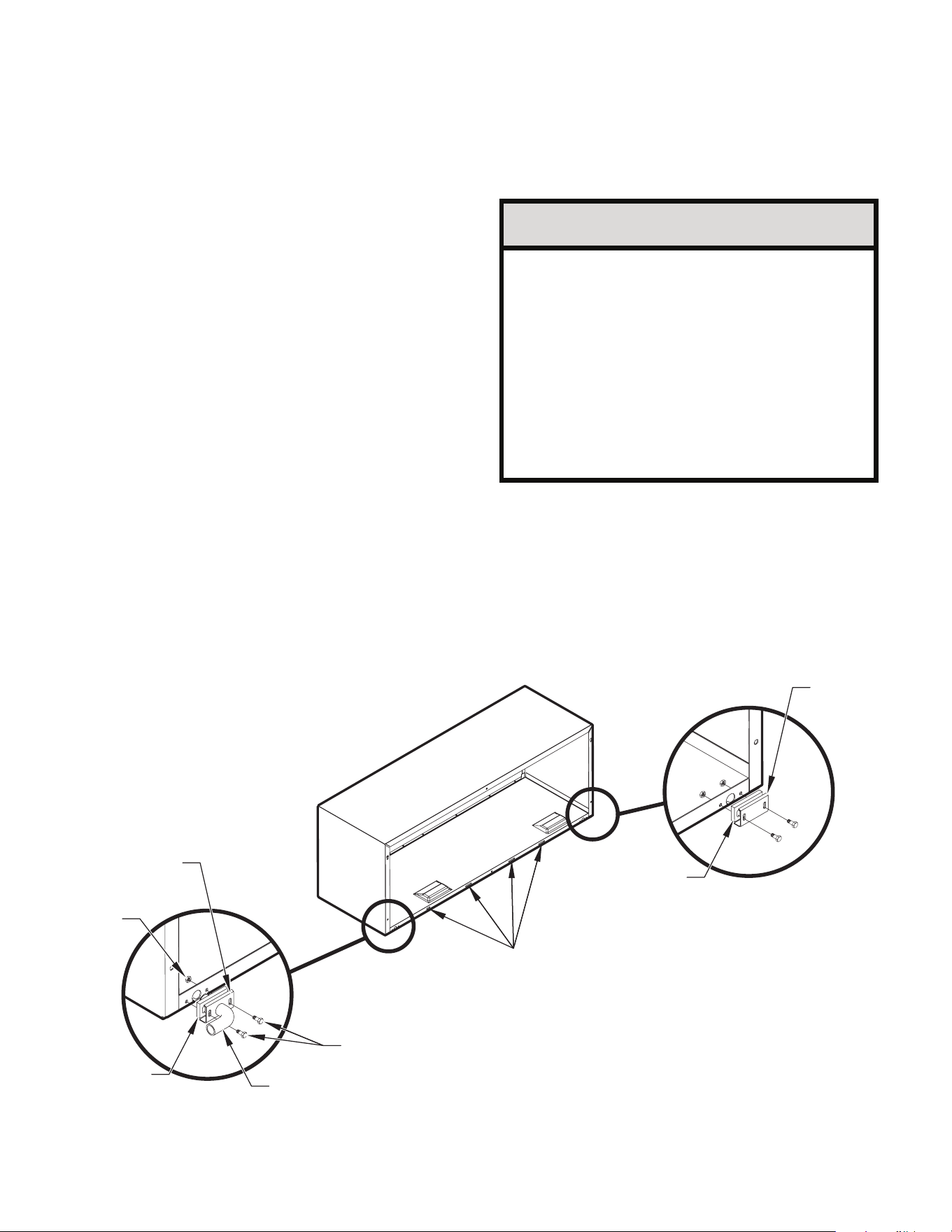
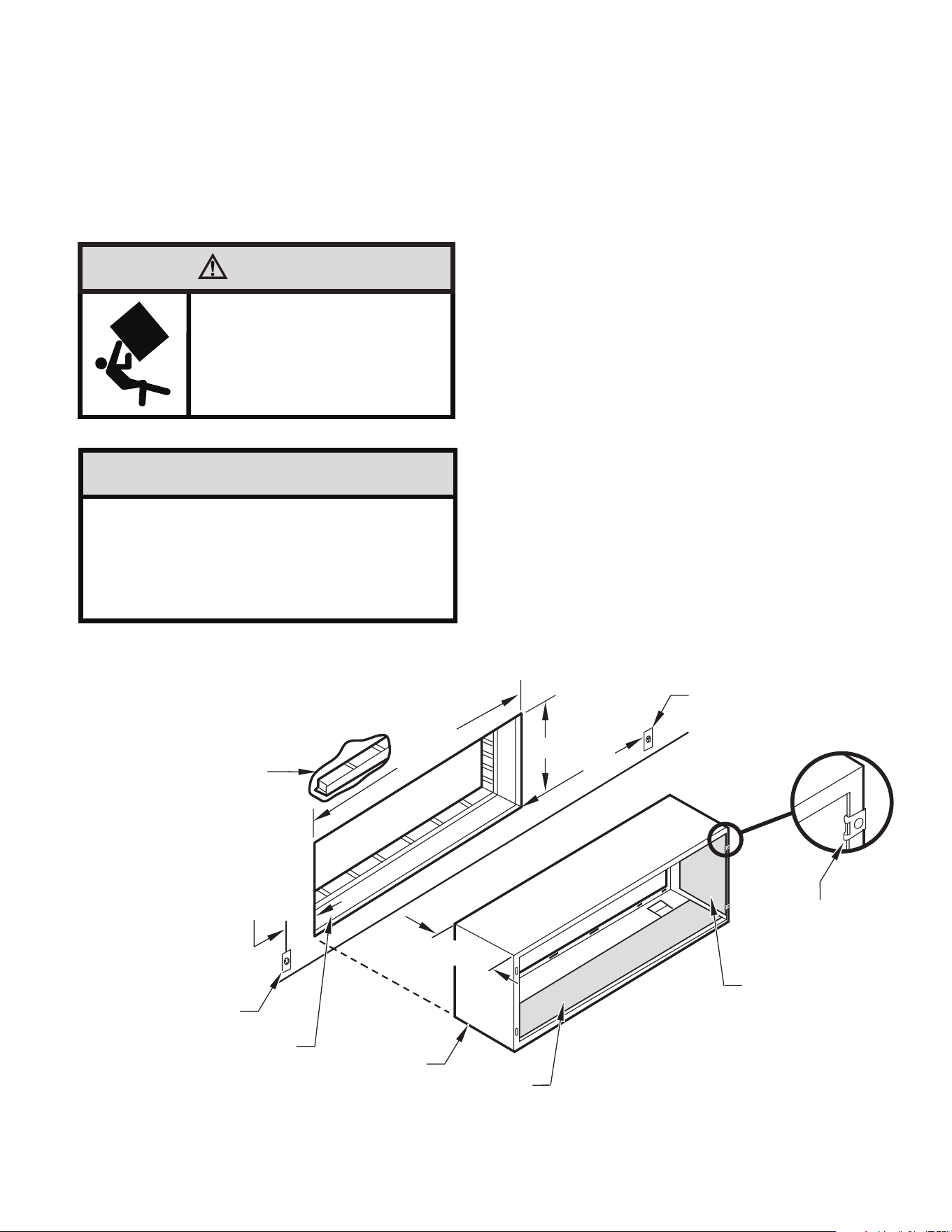
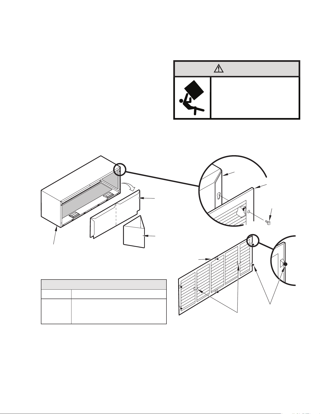
C. INSTALLATION OF THE UNIT
C.4.4 Standard Grille Instructions
1. Remove the center support and weatherboard if still installed
in the sleeve.
2. Insert six plastic grommets into the grille openings from the
outside of the grille as shown in Figure C.4.4.
3. Insert two #8 x
3/8”
sheet metal screws (provided) in the top
two outside edge plastic grommets, and tighten them half way
into the grommets.
4. Grasp the grille by the attached plastic handles. Position
it with the condensate drain knockouts facing down.
From inside the building, maneuver the grille through the wall
sleeve and pull toward you until the screw heads are inserted
into the keyhole slots at the top of the wall sleeve. Tighten the
two screws completely.
5. Insert the remaining screws into the remaining holes and tighten
securely.
WARNING
Falling Object Hazard
Not following Installation Instructions for
mounting your air conditioner can result
in property damage, injury, or death.
:
$//6/((9(
:($7+(5%2$5'
&(17(56833257
67$1'$5'*5,//(
3/$67,&+$1'/(6
3/$67,&*5200(76
:$//
6/((9(
67$1'$5'
*5,//(
[´
6+((70(7$/
6&5(:
'HVFULSWLRQ
6WDPSHG $OXPLQXP*ULOOH
3ODVWLF*URPPHWV
[Ǫ6KHHW0HWDO6FUHZV
4XDQWLW\
3;*$6WDQGDUG*ULOOH
Figure C.4.4 Standard Grille Instructions
20
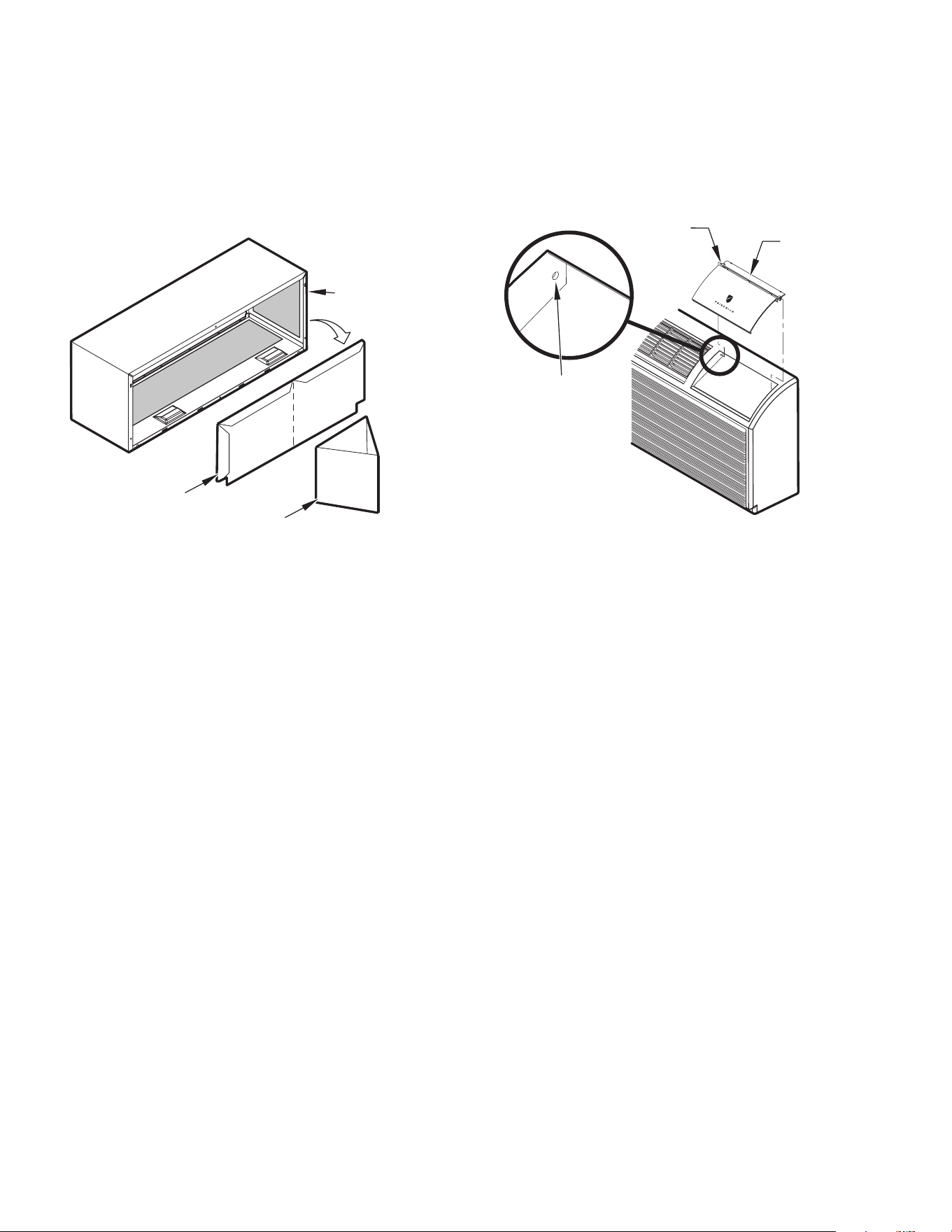
C. INSTALLATION OF THE UNIT
C.5 Chassis Install
C.5.1 Chassis Install Preparation
NOTE: Check to be sure the wall sleeve, extension (if used),
grille, and drain kit are installed properly before chassis
installation.
1. Remove the weatherboard and center support from the sleeve
(if still in place). Be sure an outdoor grille is attached.
NOTE: Use a wall sleeve adapter kit (PXSE) if installing a P-Series
chassis in a T-Series sleeve.
2. If the control door is not installed, follow these steps:
a. From the front cover, slide the right control door pin into
the hole on the right side of the front cover.
b. Slide the left door pin into the hole on the left side of the
front cover opening.
c. Snap cover into place.
NOTE: To avoid breaking the door or hinge pins, do not apply
excessive force when installing.
IMPORTANT: When installing a Friedrich PTAC into an existing sleeve,
it is important to ensure that the unit is installed completely. Inspection
of the air seal between the condenser air baffles and around the indoor
mounting flange is recommended.
In some cases additional gaskets or baffling may be required.
WALL
SLEEVE
WEATHERBOARD
CENTER SUPPORT
PIN
INSERT PIN
IN THIS LOCATION
CONTROL
DOOR
Figure C.5.1.1 Figure C.5.1.2
21
C. INSTALLATION OF THE UNIT
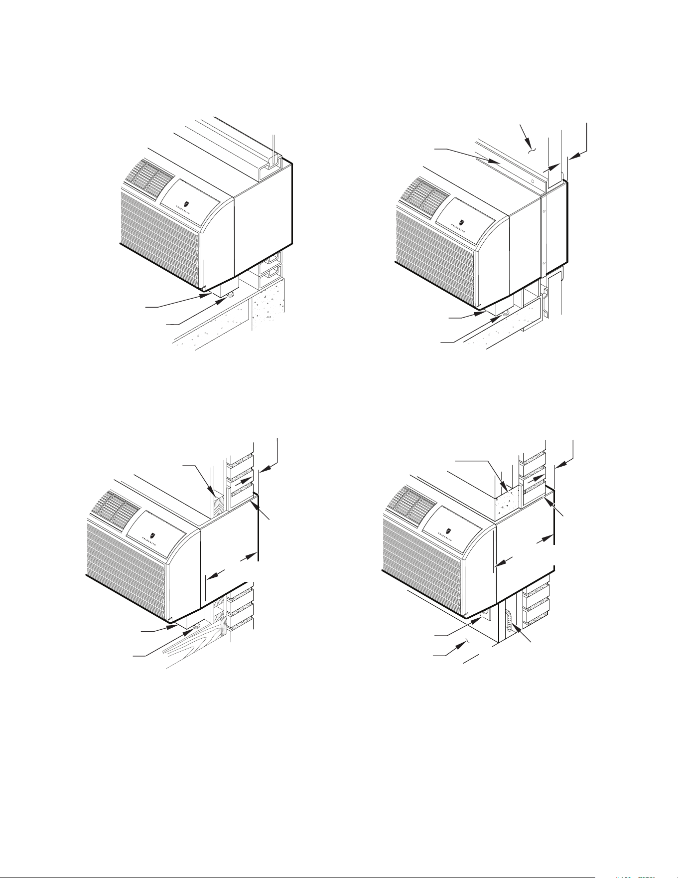
C.5.2 Chassis Install
CAUTION
Unit Damage Hazard
Failure to follow this caution may result in equipment damage
or improper operation.
Failure to remove shipping tape and screw will prevent fresh
air vent door from opening and may result in damage to vent
door cable.
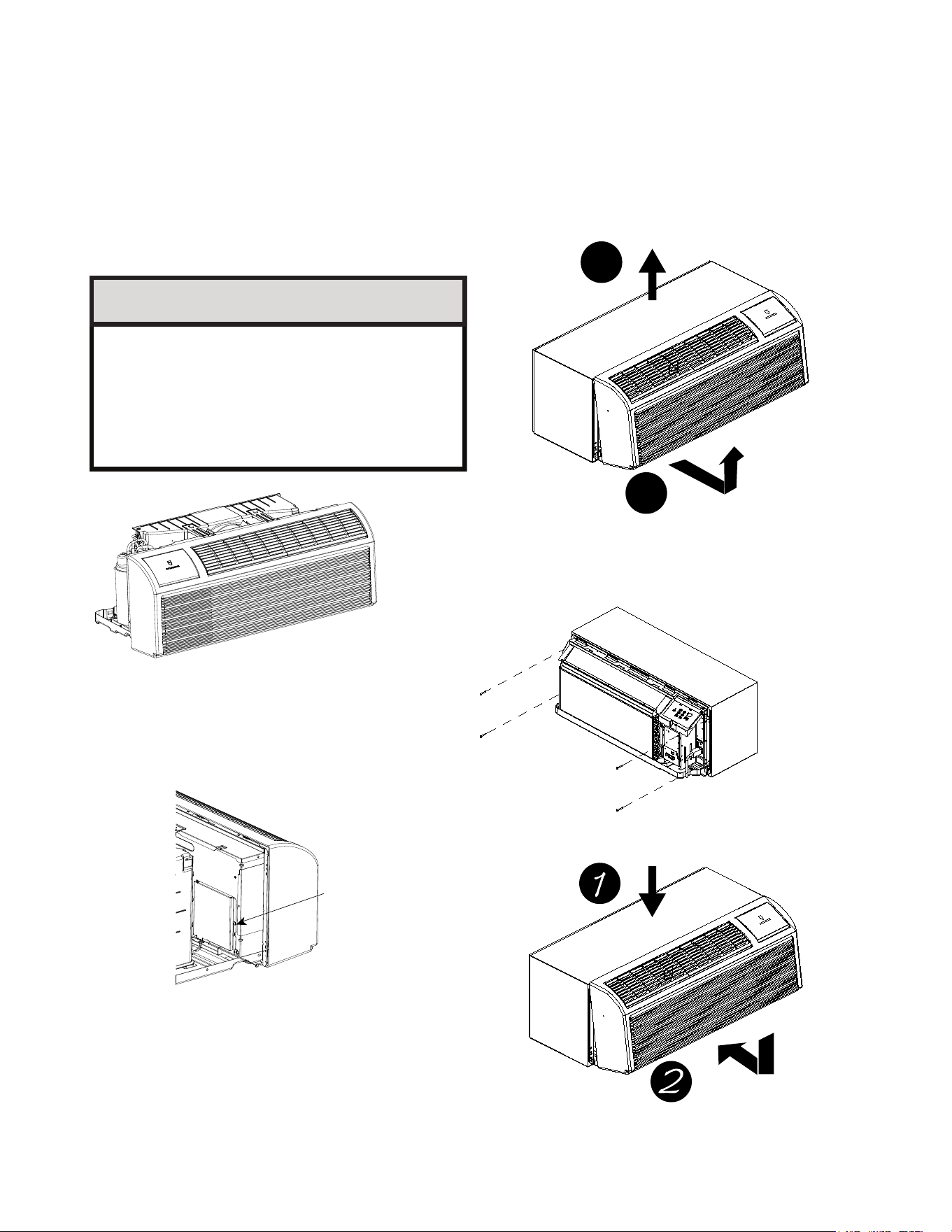
INSTALL UNIT INTO WALL SLEEVE
1.Carefully remove shipping tape from the front pa
nel and vent door.See Fig. C.5.2.1
2.Remove shipping screw from the vent door,if present.See Fig. C.5.2.2
3.Remove front panel.See Fig. C.5..2..3
4.Lift unit level and slide unit into wall sleeve until foam seal rests firmly against front of wall sleeve.
5.Secure with four screws (supplied) through the unit flange holes.See Fig.C.5.2.4
6.Reinstall front panel.See Fig.C.5.2.5
2
1
Fig.C.5.2.1–Shipping Tape Location
Pull out at the bottom to release it from the tabs
(1).Then lift up (2).
Fig. C.5.2.3 –Removing Front Panel
Remove shipping
if present.
Fig. C.5.2.2–Shipping Screw Location
Fig. C.5.2.4 –Securing Unit
Place tabs over top rail(1). Push Inward at
bottom until panel snaps into place(2).
Fig. C.5.2.5 –Replacing Front Panel
22
E.1 Electrical Safety Information
Make sure the wiring is adequate for your unit.
If you have fuses, they should be of the time delay type. Before
you install or relocate this unit, be sure that the amperage rating
of the circuit breaker or time delay fuse does not exceed the amp
rating listed in Figure E.1.1. Must be installed on a single circuit with
designated receptacle.
DO NOT use an extension cord.
The cord provided will carry the proper amount of electrical power
to the unit; an extension cord may not.
Make sure that the receptacle is compatible with the
air conditioner cord (Refer to Figure E.1.1)
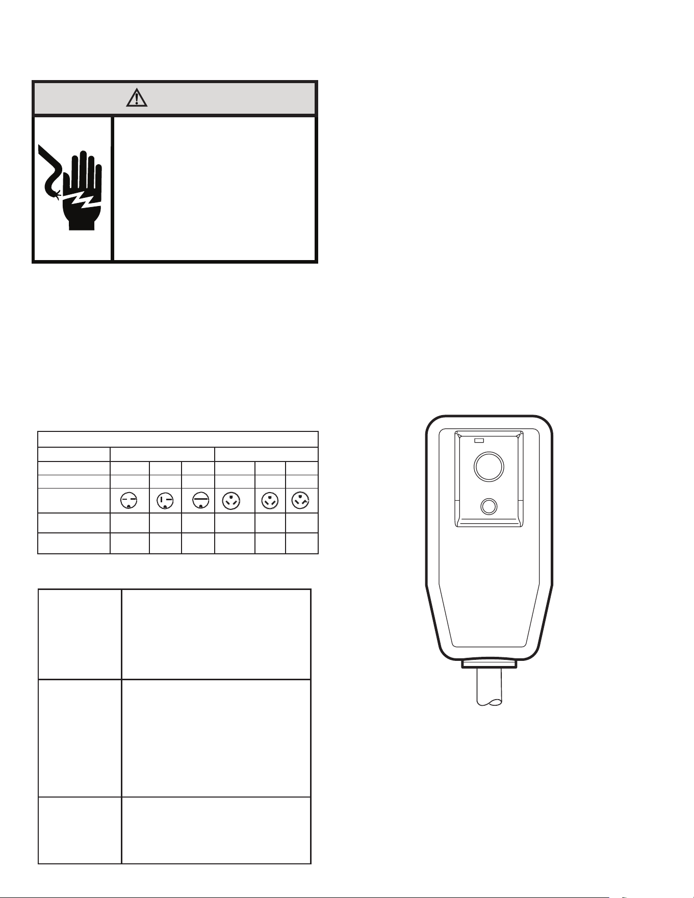
E.2 Power Cord LCDI Test
All Friedrich 230/208V PTAC units are shipped from the factory with
a Leakage Current Detection Interrupter (LCDI) equipped power
cord. The LCDI device meets the UL and NEC requirements for cord
connected air conditioners.
To test your power supply cord:
1. Plug power supply cord into a grounded 3 prong outlet.
2. Press RESET.
3. Press TEST ( listen for click; Reset button trips and pops out).
4. Press and release RESET
a. Listen for click; Reset button latches and remains in.
b. Check that the green indicator light is on once reset.
c. The power supply cord is ready for operation.
NOTE: The LCDI device is not intended to be used as a switch.
Once plugged in the unit will operate normally without the need to
reset the LCDI device.
If the LCDI device fails to trip when tested or if the power supply cord
is damaged it must be replaced with a new supply cord obtained from
the product manufacturer, and must not be repaired.
E. ELECTRICAL
WARNING
Electrical Shock Hazard
Make sure your electrical receptacle has the
same configuration as your air conditioner’s
plug. If different, consult a Licensed Electrician.
Do not use plug adapters.
Do not use an extension cord.
Do not remove ground prong.
Always plug into a grounded 3 prong outlet.
Failure to follow these instructions can result in
death, fire, or electrical shock.
RESET
TEST
WARNING:
TEST BEFORE EACH USE.
TO TEST:
PRESS RESET BUTTON.
PLUG LCDI INTO POWER
RECEPTACLE.
PRESS TEST BUTTON, RESET
BUTTON SHOULD POP UP.
PRESS RESET BUTTON FOR USE.
DO NOT USE IF TEST IS FAILED.
GREEN LIGHT INDICATES
PROPER OPERATION
FUSE/CIRCUIT
BREAKER
Use ONLY type and size fuse or HVAC/R
circuit breaker indicated on unit’s rating
plate. Proper current protection to the unit
is the responsibility of the owner.
Specication of fuse on the main board:
T3.15AH250V(unit: 208/230V)
T3.15A 350VAC(unit: 265V)
GROUNDING
Unit MUST be grounded from branch circuit
through service cord to unit, or through sep-
arate ground wire provided on permanently
connected units. Be sure that branch circuit
or general purpose outlet is grounded. The
eld supplied outlet must match plug on
service cord and be within reach of service
cord. Refer to Table 1 for proper receptacle
and fuse type. Do NOT alter the service
cord or plug. Do NOT use an extension
cord.
RECEPTACLE
The eld supplied outlet must match plug on
service cord and be within reach of service
cord. Refer to Table 1 for proper receptacle
and fuse type. Do NOT alter the service
cord or plug. Do NOT use an extension
cord.
Figure E.1.1 (Receptacles and Fuses)
Figure E.2.1 (Test LCDI)
Table 1
Voltage
230V
Receptacles and Fuse Types
265V
Amps
15 20 30 15
20
30
1.5/2.5kw
Heater Size
3.5kw
5kw
1.5/2.5kw
3.5kw
5kw
NEMA#
Receptacles
Receptacle
6-15R 6-20R 6-30R 7-15R
7-20R
7-30R
NEMA#
Plug
6-15P 6-20P 6-30P 7-15P
7-20P
7-30P
23
E.3 Electrical Wiring
E.3.1 Power Cord Installation
All 265V PTAC units come with a factory installed non-LCDI power
cord for use in a sub-base. If the unit is to be hard-wired refer to the
instructions below.
NOTE: It is recommended that the PXSB sub-base assembly, the
PXCJA conduit kit (or equivalent) be installed on all hardwired units.
If installing a flush-floor mounted unit, make sure the chassis can be
removed from the sleeve for service and maintenance.
POWER CONNECTION OPTIONS
Appropriate power cord accessory kit is determined by the voltage,
and amperage of the branch circuit. If the unit is to be hard wired, an
accessory hard wire kit must be ordered.
IMPORTANT: For 265V units, if power cord accessory option is
selected, the cord is only 18” long and must plug into the accessory
electrical 265V sub-base. Be sure that your outlet matches the
appropriate blade configuration of the plug and that it is within reach
of the service cord. All wiring, including installation of the receptacle,
must be in accordance with the NEC and local codes, ordinances and
regulations. National codes require the use of an arc fault or leakage
current detection device on all 208/230V power cords. Be sure to
select the correct cord for your installation.
Wire Size
Install a single branch circuit. All wiring must comply with local
and national codes. All units are designed to operate off ONE single
branch circuits only.
NOTE: Use copper conductors only. Prepare the 265V (or 230V)
power cord for connection to the chassis’ power cord connector by
cutting the cord to the appropriate length.
Grounding
For safety and protection, the unit is grounded through the service cord plug
or through separate ground wire provided on hard wired units. Be sure that
the branch circuit or general purpose outlet is grounded.
VOLTAGE SUPPLY
Check voltage supply at outlet. For satisfactory results, the voltage range
must always be within the ranges found on the data information plate.
Cord-connected Units
The 250V- field supplied outlet must match the plug for the standard
208/230V- units and be within reach of the service cord. The standard cord-
connected 265V- units require an accessory electrical sub-base for operation.
Refer to Table E.1.1 for proper receptacle and fuse type.
Power Cord Protection
The power cord for 230/208V units provide power cord fire protection. Unit
power automatically disconnects when unsafe conditions are detected. Power
to the unit can be restored by pressing the reset button on plug head.
Upon completion of unit installation for 230/208V models, an operational
check should be performed using the TEST/RESET buttons on the plug head.
NOTE: The 265V models do not incorporate this feature as they require use of
the electrical sub-base accessory or are hard wired. To install the line voltage
power leads and conduit to chassis, follow the instructions on the next page
and refer to figure E.3.2.
WARNING
Electrical Shock Hazard
Make sure your electrical receptacle has the
same configuration as your air conditioner’s
plug. If different, consult a Licensed Electrician.
Do not use plug adapters.
Do not use an extension cord.
Do not remove ground prong.
Always plug into a grounded 3 prong outlet.
Failure to follow these instructions can result in
death, fire, or electrical shock.
MODEL HEATER Kw POWER CORD KIT VOLTAGE AMPERAGE RECEPTACLE
PDE07K,PDE09K, PDE12K,PDE15K
PDH07K,PDH09K, PDH12K,PDH15K
2.5 PXPC23015A 208/230 15 NEMA 6-15r
PDE07K,PDE09K, PDE12K,PDE15K
PDH07K,PDH09K, PDH12K,PDH15K
3.5 PXPC23020A (STD) 208/230 20 NEMA 6-20r
PDE09K, PDE12K,PDE15K
PDH09K, PDH12K,PDH15K
5.0 PXPC23030 208/230 30 NEMA 6-30r
PDE07R,PDE09R, PDE12R,PDE15R
PDH09R, PDH12R, PDH15R
2.5 PXPC26515 265 15 NEMA 7-15r
PDE07R,PDE09R, PDE12R,PDE15R
PDH09R, PDH12R, PDH15R
3.5 PXPC26520A (STD) 265 20 NEMA 7-20r
PDE09R, PDE12R,PDE15R
PDH09R, PDH12R, PDH15R
5.0 PXPC26530 265 30 NEMA 7-30r
E. ELECTRICAL
Figure E.2.2 Power Cord Kits
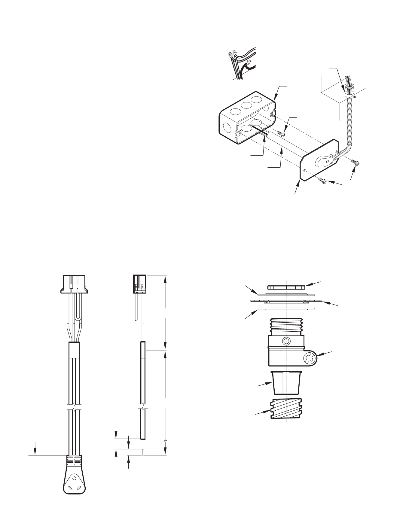
24
E. ELECTRICAL
4.0 IN.
18.0 IN.
TRIM HARNESS
TO
LENGTH
STRIP
WIRE ENDS (0.5 IN.)
TO WALL JUNCTION
TO CHASSIS JUNCTION
EXPOSE
WIRES
(1.0 IN.)
Figure E.3.1 (265v Power Cord)
E.3.1 Power Cord Installation (Cont)
PXCJA Conduit Kit is required with this setup.
Follow the removal process of the chassis’s junction box.
Route the cut ends of harness through the conduit connector
assembly and flex conduit sleeve. Be sure to use the supplied
conduit bushing to prevent damage to the cord by the conduit.
The cord should pass through the Locknut, Spacer, Chassis Junction
Box, Conduit Connector, Bushing, then the Conduit Sleeve. See
Figure E.3.2.
Route the cut ends of the power cord through the elbow connector at
the other end of the conduit. Tighten screws on elbow connector to
secure conduit sleeve.
Fasten and secure the elbow connector to the wall junction box cover
with locknut. Place and mount the wall junction box with the four
wall mounting screws making sure to pass the wall lines through the
junction box. Connect and join all wall lines with the stripped ends
using wire nuts. Tighten both screws of the wall junction box cover
to junction box.
1. Follow steps 4-6 in Section E.4 and refer to Figure E.4.2.
GROUND
SCREW
GROUND
WIRE
HARNESS
JUNCTION
BOX
WA
LL CONNECTION
JUNCTION
BOX COVER
COVER
SCREWS
STRAIGHT
CONNECTOR
Figure E.3.2 (Wall Connection)
LOCKNUT
SP
ACER
SP
ACER
BUSHING
LEADING SIDE FOR
WIRE HARNESS INSERTION
EXITING SIDE FOR
WIRE HARNESS
CHASSIS
JUNCTION
BOX
CONDUIT
CONNECT
OR
CONDUIT
SLEEVE
Figure E.3.3 (Harness Connector)
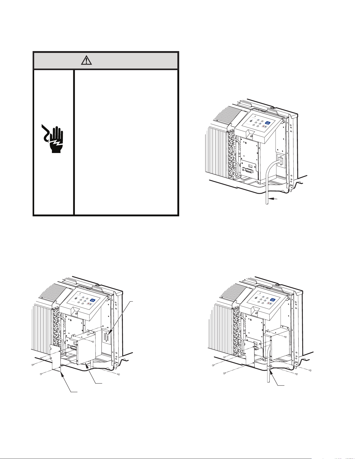
25
E. ELECTRICAL
E.4 How To Connect
IMPORTANT: Please Read The Following Electrical Safety Data Carefully
WARNING
Electrical Shock and/or Unit
Operation and Damage Hazard
Failure to follow this warning could result in
personal injury or death and/or unit damage.
●
●
●
●
●
●
●
Follow the National Electrical Code (NEC)
or local codes and ordinances.
For personal safety, this unit MUST BE
properly grounded.
Protective devices (fuses or circuit breakers)
acceptable for unit installations are specified
on the nameplate of each unit.
Do not use an extension cord with this unit.
Aluminum wiring in the building may present
special problems - consult a qualified
electrician.
When unit is in STOP position, there is
still voltage to the electrical controls.
Disconnect power to unit before servicing by:
1. Removing power cord (if it has one) from
wall receptacle.
2. Removing branch circuit fuses or turning
circuit breakers off at panel.
UNIT
CONNECT
OR
JUNCTION BOX
JUNCTION BOX COVER
High
Med
Low
Fan
Cool
Heat
Fan Speed Mode
Temperature
Power
ACCESSORY
POWER SUPPLY
CORD
OR HARD WIRE
High
Med
Low
Fan
Cool
Heat
Fan Speed Mode
Temperature
Power
WIRE CLAMP
High
Med
Low
Fan
Cool
Heat
Fan Speed Mode
Temperature
Power
1. Connect accessory power supply cord or hard wire
connector to unit connector. See Figure E.4.2.
• Units must be installed using the appropriate
power supply kit. See Table E.2.2 (Power
Connection Chart). These connections must be
followed.
1. Remove front panel. See Figure C.5.2.3.
2. Remove junction box.
• Remove junction box cover by removing three
screws from front. Remove junction box by taking out
top, rear and side screws. See Figure E.4.1.
See Table E.2.2 for power cord accessory options and ratings.
1. Reinstall junction box and cover.
• Use wire clamp to attach power cord to basepan.
Secure with screws (included) See Figure 27.
• Replace junction box and cover with screws
removed from Step 2. Tighten securely.
2. Replace front panel. See Figure 24.
Figure E.4.1 (Junction Box)
Figure E.4.2 (Power Connection)
Figure E.4.3 (Wire Clamp)
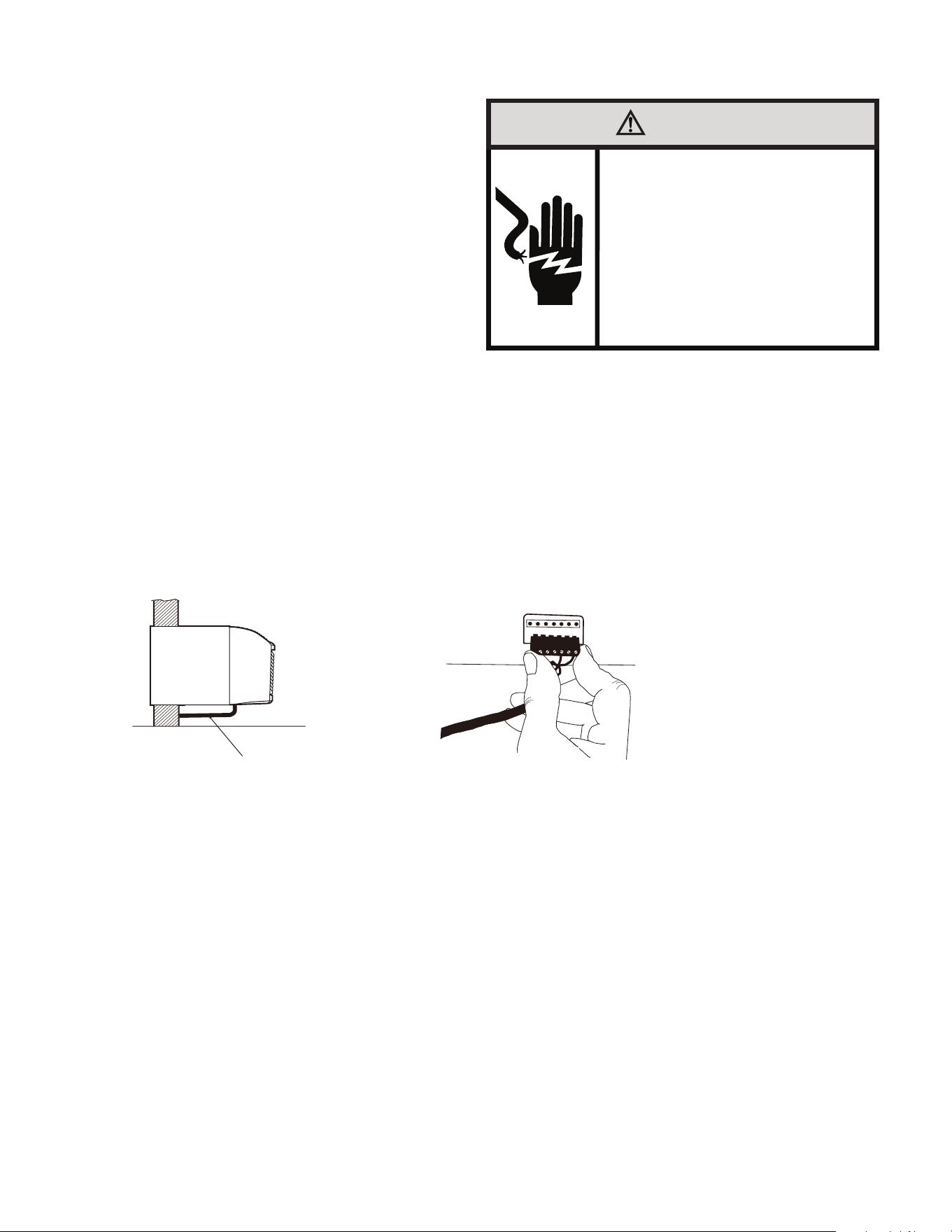
26
F. REMOTE THERMOSTATS
F.1 Install Thermostat
All PDH model PTAC units are factory configured to be controlled by either
the chassis mounted Smart Center or a 24v remote wall mounted thermostat.
The thermostat may be auto or manual changeover as long as the control
configuration matches that of the PTAC unit.
ALL PDH Models require a single stage cool, dual stage thermostat
with an O reversing valve control. The Friedrich RT7 or RT7P
thermostats are applicable.
Install thermostat Approximately 5 ft. from the floor.
Install thermostat close to or in a frequently used room, preferably
on an inside wall.
The Thermostat should NOT be mounted:
Close to a window, on an outside wall, or next to a door leading
outside.
Where it can be exposed to direct sunlight or heat, such as the sun, a
lamp, fireplace, or any other temperature radiating object which may
cause a false reading.
Close to or in the direct airflow of supply registers and/or return air
grilles.
Any areas with poor air circulation, such as a corner, behind a door,
or an alcove.
WALL THERMOSTAT TERMINAL
IMPORTANT: Only trained,qualified personnel should access electri-
cal panel on unit and install electrical accessories. Please contact
your local electrical contractor,dealer,or distributor for assistance.
Thermostat Wire Routing
Thermostat wire is field supplied. Recommended wire gauge is 18 to
20 gauge solid thermostat wire.
NOTE: It is recommended that extra wires are run to unit in case any
are damaged during installation. Thermostat wire should always be
routed around or under, NEVER through,the wall sleeve. The wire
should then be routed behind the front panel to the easily accessible
terminal connector.
WARNING
Electrical Shock Hazard
Make sure your electrical receptacle has the
same configuration as your air conditioner’s
plug. If different, consult a Licensed Electrician.
Do not use plug adapters.
Do not use an extension cord.
Do not remove ground prong.
Always plug into a grounded 3 prong outlet.
Failure to follow these instructions can result in
death, fire, or electrical shock.
WALL THERMOSTAT TERMINAL
IMPORTANT: Only trained,qualified personnel should access electrical panel on unit and install
electrical accessories.Please contact your local electrical contractor,dealer,or distributor for
assistance.
Thermostat Wire Routing
Thermostat wire is field supplied.Recommended wire gauge is 18 to 20 gauge solid thermostat wire.
NOTE: It is recommended that extra wires are run to unit in case any are damaged during installation.
Thermostat wire should always be routed around or under, NEVER through,the wall sleeve. The wire
should then be routed behind the front panel to the easily accessible terminal connector.
THERMOSTAT WIRE ROUTING
(UNDER SLEEVE, BEHIND FRONT PANEL)
R W Y O Gh Gl C
Fig. F.1.1 –Proper Wire Routing Beneath Unit
Fig. F.1.2–Terminal Connector Removal and Replacement
Wiring Thermostat To Unit
Wire wall thermostat input as defined in Fig. F.2.2
NOTE: Terminal connector can be removed and replaced to simplify the wiring.
NOTE: For heat pump models,anytime there is a second-stage call for heating from the wall thermostat,
the unit will automatically switch over to electric heating.
Install Thermostat Wiring
2. Pull terminal connector to remove
NOTE:Terminal connector can be removed and replaced to simplify thermostat wiring.
3. Connect wires from the thermostat to terminals on unit terminal connector.
4. Reinstall terminal connector.
5. Ensure that unit is cofigured for wall thermostat enable.
6. Replace control panel label with wall thermostat label(included).
7. Restore power to unit.
NOTE: Refer to thermostat installation instructions for details on installing wall thermostat.
NOTE: For thermostats that have only one fan speed output (on or auto), the fan speed is determined
by how the terminal connector is wired. If Low fan is desired, wire the G output from the thermostat to
GL on the unit’s terminal block. If Hi fan is desired, wire the G output from the thermostat to GH on the
unit’s terminal block.
NOTE: After proper installation, if your thermostat is not working properly, refer to the Trouble Shooting
section.
14
1. Ensure that power is disconnected.
NOTE: Refer to Table J.3.3 (Dip Switch Functions) to set the thermostat mode.
Wire wall thermostat input as defined in Fig. F.2.2
NOTE: Terminal connector can be removed and replaced to simplify the
wiring.
NOTE: For heat pump models,anytime there is a second-stage call for heating
from the wall thermostat, the unit will automatically switch over to electric
heating.
Install Thermostat Wiring
2. Pull terminal connector to remove
NOTE: Terminal connector can be removed and replaced to simplify thermo-
stat wiring.
3. Connect wires from the thermostat to terminals on unit terminal connector.
4. Reinstall terminal connector.
5. Ensure that unit is configured for wall thermostat enable.
6. Replace control panel label with wall thermostat label (included).
7. Restore power to unit.
NOTE: Refer to Table J.3.3 (Dip Switch Functions) to set the thermostat mode.
NOTE: Refer to thermostat installation instructions for details on installing
wall thermostat.
NOTE: For thermostats that have only one fan speed output (on or auto), the
fan speed is determined by how the terminal connector is wired. If Low fan
is desired, wire the G output from the thermostat to GL on the unit’s terminal
block. If Hi fan is desired, wire the G output from the thermostat to GH on the
unit’s terminal block.
NOTE: After proper installation, if your thermostat is not working properly,
refer to the Trouble Shooting section.
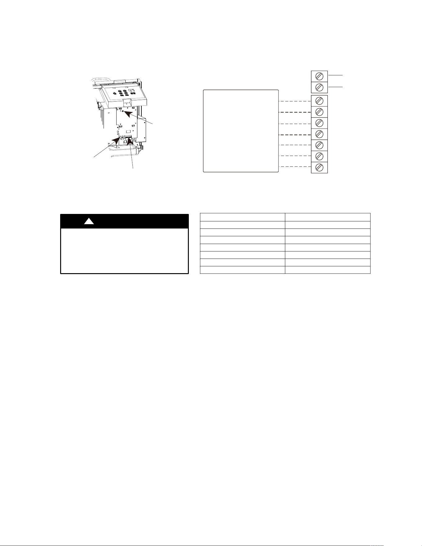
27
F. REMOTE THERMOSTATS
F.2 Terminal Connections
TERMINAL CONNECTIONS
The wall thermostat terminal block is located behind the front panel and is easily accessible on front
of control panel.
R
Y
GH
GL
C
W
O
Common
(24VAC in)
TYPICAL WALL THERMOSTAT
TERMINAL BLOCK
See Note 1
See Note 2
Energy
Management
NOTES:
1.Use terminal“O” for heat pump unit connection only.
2.Terminal“C”(common) is typically only required for digital thermostats.
TERMINAL DESIGNATION
R 24VAC
W Electric Heat
Y Compressor
O Reve
r
sing Valve
GH High Fan
GL Low Fan
C Common
Fig. F.2.1 –Terminal Connector and Status LED Location
UNIT DAMAGE HAZARD
CAUTION
!
Failure to follow this caution may result in equipment
damage or improper operation.
Improper wiring may damage unit electronics.
Common busing is not permitted.Damage or erratic
operation may result.
ENERGY MANAGEMENT INPUT (FRONT DESK CONTROL)
The controller can handle a switch signal from remote energy management input, called EM signal or
front desk control. Input must be 24VAC. If system receives a 24VAC signal,it will turn unit off; otherwise,
the unit runs in normal control.This function will be disabled under Freeze Guard protection. See Fig. F.2.1
and Fig. F.2.2 for terminal connections.
NOTE: Any errant input combinations will be captured as thermostat wiring
failures and will light the STATUS LED indicator on main board
(see Intelligent Self---Checking Control section).
STATUS
LED
Wall Thermostat
Terminal Connections
Energy Management
Terminal Connections
Fig. F.2.2
J. STARTUP AND OPERATION
J.1 Final Inspection
• Inspect and ensure that all components and accessories have
been installed properly and that they have not been damaged
during the installation progress.
• Check the condensate water drain(s) to ensure that they are
adequate for the removal of condensate water, and that they
meet the approval of the end user.
• Ensure that all installation instructions concerning clearances
around the unit have been adhered to. Check to ensure that
the unit air filter, indoor coil, and outdoor coil are free from any
obstructions.
• Inspect the unit for any damage to the coils and tubing that could
cause a leak.
• Ensure that the circuit breaker(s) or fuse(s) and supply circuit
wire size have been sized correctly. If the unit was supplied with
a power supply cord, insure that it is stored properly.
• Ensure that the entire installation is in compliance with all
applicable national and local codes and ordinances having
jurisdiction.
• Secure components and accessories, such as a decorative front
cover.
• Start the unit and check for proper operation of all components in
each mode of operation.
• Instruct the owner or operator of the units operation, and the
manufacturer’s Routine Maintenance.
NOTE: A log for recording the dates of maintenance and/ or service
is recommended.
Present the owner or operator of the equipment with the
Installation & Operation Manual, all accessory installation
instructions, and the name, address, and telephone number of the
Authorized Friedrich Warranty Service Company in the area for
future reference if necessary. Inspect the unit for any damage to
the coils and tubing that could cause a leak.
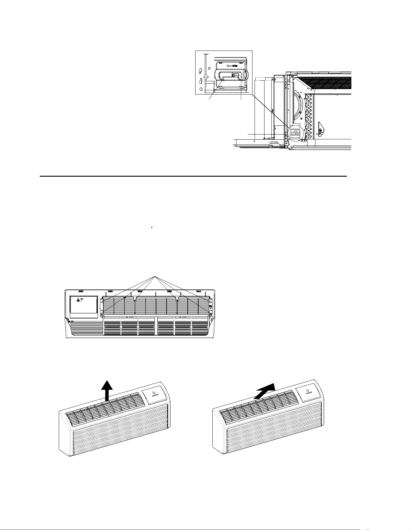
28
J. STARTUP AND OPERATION
J.2 Air Flow Selection and Adjustment
VENTILATION CONTROL
The ventilation control lever is located at left
side of unit, behind front panel.
NOTE:The vent door shipping hardware must be
removed before using vent control lever. See
Installation Instructions.
When set at close POSITION, only the air inside
the room is circulated and filtered.
When set at open POSITION, some outdoor air
will be drawn into room. This will reduce heating
or cooling efficiency.
EnergyTip : Keep the vent control at closed
POSITION. Room air will be filtered and
circulated.
Figure 301 (Ventilation Control Location)
ADJUSTING AIR DIRECTION
To adjust air direction:
1. Remove front panel.
2. Remove louver screws that hold louver insert in place (from back side of front panel). See Fig. 301
3. Turn louver insert and rotate 180 See Fig.302
4. Replace louver insert.
5. Replace screws and front panel.
Louver screws
Figure 302 (Backside of Front Panel)
Air discharge upward
Air discharge outward (Default)
Figure 303 (Adjusting Louvers)
Vent Control
(Pull lever through label
to operate.)
Open position Close position
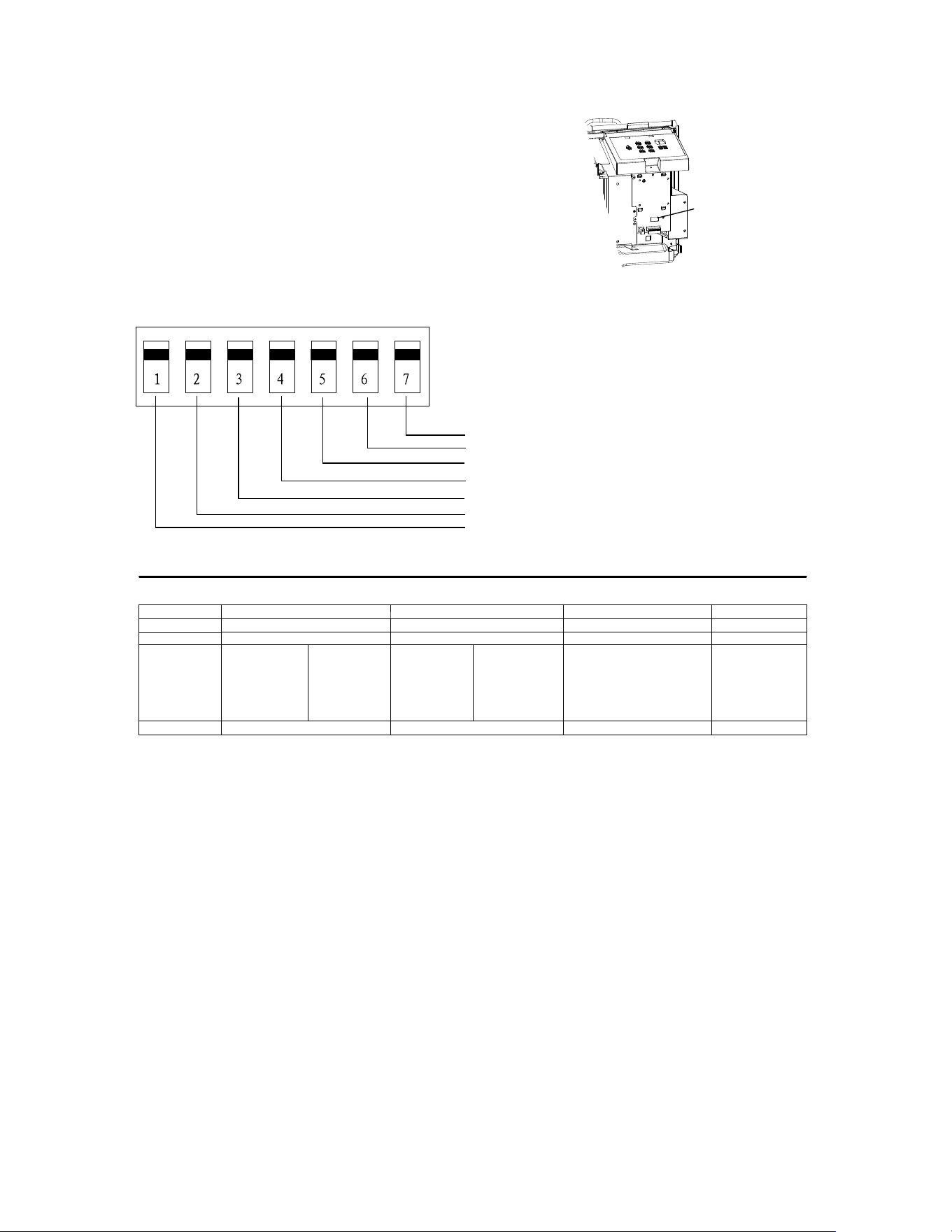
29
J. STARTUP AND OPERATION
J.3 Dip Switches
Auxiliary dip switch controls are located behind front
panel, through an opening below the control panel.
To access, remove front panel.
Dip switches are accessible without opening the
control box. Unit must be powered OFF to
effectively change their status.
Factory settings for dip switches will be in the DOWN
position. See Table 5-Dip Switch Functions for
functions of each dip switch position.
Dip Switches
Figure 304 (Dipswitch Location on Unit)
Figure 305 (Dip Switches)
UP
Dow
n
Dip switch
Freeze guard
Setpoint Limit 2
Setpoint Limit 1
Wall Thermostat enable
Electric heat only (for Heat Pumps )
Table306 (DIP SWITCH FUNCTIONS)
No. UP DOWN REMARKS DEFAULT
1 DOWN
2 DOWN
6
*
5
UP*UP
68 ---75°F
UP* DOWN
63 ---80°F
DOWN* UP
65 ---78°F
DOWN* DOWN
61 ---86°F
(full range)
Two con figurations (5* 6)
combine to selec t set point
range.
When set point limit set, dis-
play al
wa
ys sh
o
ws full
range.
DOWN* DOWN
61 ---86°F
7 Freeze Guard Disable Freeze Guard Enable DOWN
Electric Heat Only
Wall Thermostat Enable
Heat Pump
Control Panel Enable
For Heat Pump unit only.
Electric Heating Only/Emergency Heat (For Heat Pump Units Only)
This setting is typically used for Emergency Heating.
Wall Thermostat Enable
A wired wall thermostat can be connected to the unit. If it is, this dipswitch must be moved to the Wall
Thermostat Enable Position, before the wall thermostat will begin control.
Setpoint Temperature Limits
Provides a restricted range of temperature control.
Room Freeze Protection
If unit senses a room temperature below 40°F, the fan motor and electric strip heat will turn on and
warm the room to 50°F. The fan stops a short time after the temperature is satisfied.
12
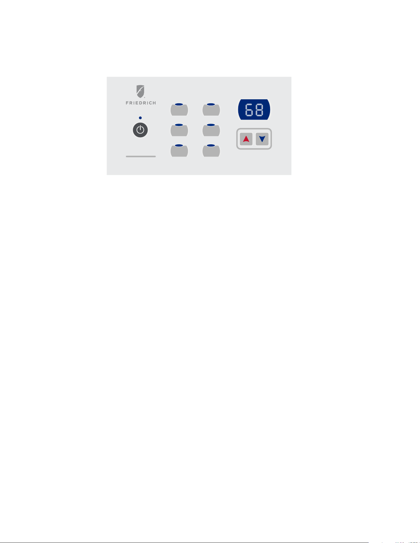
30
J. STARTUP AND OPERATION
J.4 Control Panel Operation
IMPORTANT : When unit is first started,high humidity conditions can cause condensation to form on discharge grille.Keep doors and windows
closed .Room humidity will decrease and moisture will evaporate.
OPERATION
IMPORTANT : When unit is first started,high humidity conditions can cause condensation to form
on discharge grille.Keep doors and windows closed.Room humidity will decrease and moisture will
evaporate.
Fig.26–PTAC CONTROLS
17
High
Low
Auto
Constant
Fan
Cool
Heat
Fan Speed Mode
Temperature
Power
ABOUT THE CONTROLS ON YOUR UNIT
NOTE:In case of a power failure,the unit will remember the last programmed settings and will
restart to those settings.
1.When the unit is in off mode, turn on the unit by Power; if pressing up/down button, dual-8
will off after indoor temperature displays for 15s; if pressing mode button, controller will resume
to related state, and operation indication lamp will on (mode button including cooling mode button,
heating mode button and fan mode button)
* Power: It will shift when the unit is Power by Power.
* Cooling mode button: when the unit is on, it will run under cooling mode; when the unit is off, press
cooling mode button, controller is on and runs under cooling mode.
* Heating mode button: when the unit is on, it will run under heating mode; when the unit is o ff, press
heating mode button, con troller is on and runs under heating mode.
* Constant Fan button: when the unit is on, it will run under fan mode; when the unit is off, press fan mode
button, controller is on and runs under fan mode.
* Low speed button: when the unit is on, low fan will be chose if pressing low fan button.
* High speed button: when the unit is on, high fan will be chose if pressing high fan button.
Auto
speed button: When the unit is on, press Auto button,the unit will run at the mode automatically
adjusted according to ambient temperature.
*
*
UP/DOWN: Adjust preset temperature
61-86°F 16-30°C by UP/DOWN.
2.Every button is valid when the unit is on.
ABOUT THE CONTROLS ON YOUR UNIT
NOTE: In case of a power failure,the unit will remember the last programmed settings and will restart to those settings.
1. When the unit is in off mode, turn on the unit by Power; if pressing up/down button, dual-8 will off after indoor temperature displays for 15s;
if pressing mode button, controller will resume to related state, and operation indication lamp will on (mode button including cooling mode
button, heating mode button and fan mode button)
2. Every button is valid when the unit is on.
• Power: It will shift when the unit is Power by Power.
• Cooling mode button: when the unit is on, it will run under cooling mode; when the unit is off, press cooling mode button, controller is on
and runs under cooling mode.
• Heating mode button: when the unit is on, it will run under heating mode; when the unit is off, press heating mode button, controller is on
and runs under heating mode.
• Constant Fan button: when the unit is on, it will run under fan mode; when the unit is off, press fan mode button, controller is on and runs
under fan mode.
• Low speed button: when the unit is on, low fan will be chose if pressing low fan button.
• High speed button: when the unit is on, high fan will be chose if pressing high fan button.
• Auto speed button: When the unit is on, press Auto button,the unit will run at the mode automatically adjusted according to ambient tem-
perature.
• UP/DOWN: Adjust preset temperature 61-86°F 16-30°C by UP/DOWN.

31
J. STARTUP AND OPERATION
J.5 Allocation Mode
Allocation mode will be started up if pressing the buttons of low speed and Set-point down for 5S when the unit is on in 30S . After entering
into allocation mode, adjust temperature compensation by buttons which leads the unit in on/off condition, and it acts after it overloads 3S; if
ambient temperature changing leads the unit in on/off condition, it will act after exit allocation mode.
Under allocation mode: Choose below 4 allocation modes by low speed button.
First Mode: Fahrenheit/Celsius display mode
The Fahrenheit/Celsius display mode will be shifted if pressing Set-point up or Set-point down.
F means Fahrenheit display mode C means Celsius display mode.
Second Mode: Adjust cooling temperature compensation value mode
Press Set-point up/Set-point down will increase/decrease compensation temperature 1°F(or °C).
The adjust range of indoor ambient temperature compensation value is -6°F~+6°F(-3°C~+3°C)
(Cooling mode LED is on.)
Third Mode: Adjust heating temperature compensation value mode
Press Set-point up/Set-point down will increase/decrease compensation temperature 1°F (or °C)
The adjustment range of indoor ambient temperature compensation value is -6°F~+6°F(-3°C~+3°C)
(Heating mode LED is on.)
The temperature compensation is default 0 and allocates different compensation value under cooling and heating mode, the compensation
value can not be adjusted under fan mode
Forth Mode: Display shift of preset temperature and ambient temperature under heating and cooling mode. Display of preset temperature and
ambient temperature can be shifted if pressing Set-point up or Set-point down. Preset temperature display: dual-8 displays SP, after exiting
allocation mode, preset temperature will display under heating and cooling mode.
Ambient temperature display: dual-8 displays AA, after exit allocation mode, ambient temperature will display under heating and cooling mode.
In below situation: preset temperature will display 10S, then display ambient temperature.
1. Press mode button. (Mode button includes: cooling mode button, heating mode button)
2. Energization after power off.
3. Turn off the unit after turn on unit.
4. EM off after on.
5. Adjust preset temperature by Set-point up and Set-point down.
Exiting measure of allocation mode: for above allocation mode, there is no button action if pressing mode button (including cooling mode
button, fan mode button and heating mode button) or in 30S, the unit will exit allocation mode.

32
M. TROUBLESHOOTING
M.1. Troubleshooting Tips
SYMPTOM POSSIBLE CAUSES SOLUTIONS
UNIT DOES NOT START • Unit may have become unplugged
• Fuse may have blown
• Circuit breaker may have been tripped
• Unit may be off or in wall thermostat mode.
• Check section on dip switch settings to verify dip
switches are set properly.
• Unit may be in a protection or diagnostic failure mode.
See section on Intelligent Self- checking Control.
• Check that plug is plugged securely in wall receptacle.
• Note : Plug has a test/reset button on it. Make sure that
the plug has not tripped.
• Replace the fuse. See Note 1.
• Reset circuit breaker. See Note 1.
• Turn unit on (bottom right button on keypad).
• Note: If the unit turns on, the LED will be green. If the
unit is off, the LED will be red. If there is no LED on,
there is a problem with power or damage to the control.
UNIT NOT COOLING/
HEATING ROOM
• Unit air discharge section is blocked
• Temperature setting is not high or low enough Note:
Set-point limits may not allow the unit to heat or cool
the room to the temperature desired.
• Check section on dip switch settings.
• Unit air filters are dirty.
• Room is excessively hot or cold when unit is started.
• Vent door left open
• Unit may be in a protection or diagnostic failure mode.
Check section on Intelligent Self---checking Control.
• Compressor is in time delay. There is a protective time
delay (approx. 3 minutes) on starting the compressor
after a power outage (or restarting after it has been
turned off), to prevent tripping of the compressor
overload.
• Make sure that curtains, blinds or furniture are not
restricting or blocking unit airflow.
• Reset to a lower or higher temperature setting.
• Remove and clean filters.
• Allow sufficient amount of time for unit to heat or cool
the room.
• Start heating or cooling early before outdoor
temperature, cooking
• Heat or gatherings of people make room uncomfortable.
• Close vent door.
• Check dip switch settings for desired comfort.
• Wait approximately 3 minutes for compressor to start
DISPLAY HAS STRANGE
NUMBERS/CHARACTERS
ON IT
• The unit may be in a diagnostic condition.
• The unit may be set for C (instead of F).
• Check Intelligent Self - checking Control section to
determine if unit has had a failure.
• See the keypad configuration section.
UNIT MAKING NOISES • Clicking, gurgling and whooshing noises are normal
during operation of unit.
WATER DRIPPING
OUTSIDE
• If a drain kit has not been installed, condensation
runoff during very hot and humid weather is normal.
See Note 2. If a drain kit has been installed and is
connected to a drain system, check gaskets and fittings
around drain for leaks and plugs.
WATER DRIPPING INSIDE • Wall sleeve is not installed level • Wall sleeve must be installed level for proper drainage
of condensation. Check that installation is level and
make any necessary adjustments.
ICE OR FROST FORMS ON
INDOOR COIL
• Low outdoor temperature
• Dirty filters
• When outdoor temperature is approximately 55 F or
below, frost may form on the indoor coil when unit is in
Cooling mode. Switch unit to FAN operation until ice or
frost melts.
• Remove and clean filters.
COMPRESSOR
PROTECTION
• Power may have cycled, so compressor is in a restart
protection.
• Random Compressor restart - Whenever the unit is
plugged in, or power has been restarted, a random
compressor restart will occur. After a power outage, the
compressor will restart after approximately 3 minutes.
• Compress or Protection -To prevent short cycling of
the compressor, there is a random startup delay of
3 minutes and a minimum compressor run time of 3
minutes.
NOTES:
1.If circuit breaker is tripped or fuse is blown more than once,contact a qualified electrician.
2.If unit is installed where condensation drainage could drip in an undesirable location,an accessory drain kit should be installed and connected to drain
system
33
M. TROUBLESHOOTING
M.2 Diagnostic Codes
STATUS LED Indicator Definitions
INTELLIGENT SELF--CHECKING CONTROL
Your PTAC has a computer board that continuously checks key components of the unit to ensure they are operating properly. Under normal op-
eration, unit status indicator (STATUS,on main PCB), light is steadily ON. If there is a major problem,the unit will shut down and display a diag-
nostic failure code on the unit’s display. If it is only a minor failure and unit is correcting the fault by itself, the diagnostic code will be flashed on
the status LED that can easily be seen when the front panel is removed (see Fig. C.5.2.3). Failure STATUS codes are defined in the table below.
Diagnostic
Code
Description Status Indicator
F1
Indoor ambient temperature sensor is open circuited or short-
circuited.
Dual-8 nixie tube displays“F1” and STATUS indicator will flash once
and off 3s circularly.
F2 Indoor tube temperature sensor is open circuited or short-circuited.
Dual-8 nixie tube displays“F2” and STATUS indicator will flash twice
and off 3s circularly.
F3
Outdoor ambient temperature sensor is open circuited or short-
circuited.
Dual-8 nixie tube displays“F3”.
F4
Outdoor tube temperature sensor is open circuited or short-
circuited.
Dual-8 nixie tube displays“F4” and STATUS indicator will flash four
times and off 3s circularly.
FJ Malfunction of temperature sensor at air outlet. Dual-8 nixie tube displays “FJ”.
FP
Low temperature prevention protection. Dual-8 nixie tube displays “FP”.
Wrong wire connection indication for wired controller. STATUS indicator will flash nine times and off 3s circularly.
High temperature prevention protection for evaporator. STATUS indicator will flash eight times and off 3s circularly.
High temperature prevention protection for outdoor condenser. STATUS indicator will flash six times and off 3s circularly.
Freeze prevention protection for evaporator. STATUS indicator will flash five times and off 3s circularly.
Frost prevention (heat pump). STATUS indicator will flash seven times and off 3s circularly.
F0 Freon-lacking protection. Dual-8 nixie tube displays “F0”.
H3 Overload detection protection. Dual-8 nixie tube displays “H3”.
E5 Over-current protection of compressor. Dual-8 nixie tube displays “E5”.
A2
Malfunction protection for electric heating Relay for Compressor or
heater is broken.
Dual-8 nixie tube displays “A2”.
U5
Unbalanced Electric Current detected between Null line and live
line.
Dual-8 nixie tube displays “U5”.
A0 Electric heater combination wrong. Dual-8 nixie tube displays “A0”.
A4 Electric heater current abnormal. Dual-8 nixie tube displays “A4”.
C7 Temperature limiter protection time too long. Dual-8 nixie tube displays “C7”.
For advanced troubleshooting and repair by
qualified service technicians:
Scan this QR code to be linked to our professional
support page where you can locate the Service
Manual.
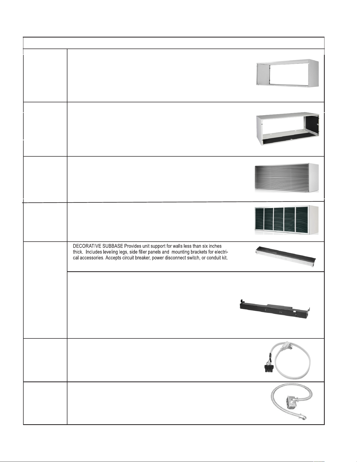
34
P. ACCESSORIES
PDXWSA
PDXWSEXT
WALL SLEEVE Galvanized zinc coated steel is prepared in an 11 step process,
then powder coated with a polyester finish and cured in an oven for exceptional
durability. The wall sleeve is insulated for sound absorption and thermal efficiency.
16” High x 42” Wide x 13 3/4 “ Deep
DEEP WALL SLEEVE EXTENSION For use when the wall is thicker than 13 1/4’ deep.
The wall sleeve may be special ordered through your sales representative and will
cut to your specific depth requirement.
PDXGA
GRILLE Standard, stamped aluminum, anodized to resist chalking and oxidation.
PXAA
PXBG
PXSC
ARCHITECTURAL GRILLES consist of heavy gauge 6063-T5 aluminum alloy:
PXAA - Clear extruded aluminum.
PXBG - Beige acrylic enamel.
PXSC- Custom color Hurricane louver with Miami Dade Certification.
WALL SLEEVE An easy and effortless snap together design. Galvanized zinc coated
steel is prepared in an 11-step process, then powder coated with a polyester finish
and cured in an oven for exceptional durability. The wall sleeve is insulated for
sound absorption and thermal efficiency, 16" High x 42" Wide x 13 3/4" Deep.
PDXWSEZ
PXAAHD
PXAAHD- Clear, extruded Aluminum Hurricane louver with Miami Dade Certification.
ELECTRICAL SUBBASE Provides unit support for walls less than six inches
thick. Includes leveling legs, side filler panels, mounting brackets, a plug
in receptacle and field wiring access. The subbase also includes electrical
knockouts for a power disconnect switch or circuit breaker.
PXSB23020 - electrical subbase - 230v 15& 20A
PXSB23020 - electrical subbase - 230v 30A
PXSB26515 - electrical subbase - 265v 15A
PXSB26520 - electrical subbase - 265v 20A
PXSB26530 - electrical subbase - 265v 30A
POWER CORDS
PXPC23015A LCDI 230V 15A Cord -2.5 kW 6 ft. length
PXPC23020A LCDI 230V 20A Cord -3.5 kW 6 ft. length
PXPC23030 LCDI 230V 30A Cord -5.0 kW 6 ft. length
PXPC26515A Non-LCDI 265V 15A Cord -2.5kW 18 in. length
PXPC26520A Non-LCDI 265V 20A Cord -3.5kW 18 in. length
PXPC26530A Non-LCDI 265V 30A Cord -5.0 kW 18 in. length
PXCJA
CONDUIT KIT WITH JUNCTION BOX Hard wire conduit kit with junction box for
208/230V and 265V units (subbase not required). Kit includes a means of quick
disconnect for easy removal of the chassis. *Required for 265V installations.
PXSBA
New Construction Accessories
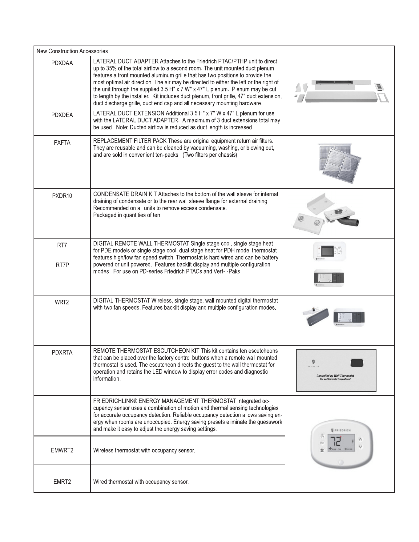
35
P. ACCESSORIES
01
2 3 4 ÿ6 7 8 9 78ÿ399739
ÿ 6 ÿ ÿ 3 9 ÿ7 ÿ 3 ÿ 3 ÿ 6 ÿ 8 ÿ7 ÿ 3 ÿ
ÿ!" ÿ# $ % ÿ" &ÿ!' ( ÿ!" !) *ÿ) +,- " . ÿ!" ÿ) ÿ/ ( 0 " 1 2 ÿ," " 3 4ÿ5 ' ( ÿ 1 +!ÿ3 " 1 !( 2 ÿ2 0 !ÿ *( 1 3 ÿ
63 3 9 ÿ ÿ67 8 ÿ7 7 8 3 ÿ 8 7 8 7 ÿ9 883 ÿ ÿ 9 ÿ4 7 ÿ: 7 9 7 8 9 ÿ7 ÿ: 7 ; 3 ÿ 3 ÿ
7 7 9 ÿ7 : 7 8ÿ ÿ 3 7 8 <ÿ 3 ÿ ÿ7 = ÿ> 3 ÿ 3 3 ÿ7 ÿ3 3 ÿ 3 ÿ83 6ÿ7 ÿ 3 ÿ9 ÿ7 6ÿ
!' ( ÿ 1 +!ÿ!' ," ? ' ÿ!' ( ÿ/ *+( 2 ÿ# 4$ ÿ@ AÿB ÿC ÿDAÿB ÿE C AÿF ÿ *( 1 3 4ÿÿG *( 1 3 ÿ3 ) H ÿI ( ÿ0 !ÿ
!" ÿ*( 1 ? !' ÿI H ÿ!' ( ÿ+1 / !) **( ,4ÿÿJ +!ÿ+1 0 * 2 ( / ÿ2 0 !ÿ *( 1 3 Kÿ&," 1 !ÿ? ,+**( KÿE C Aÿ2 0 !ÿ( B !( 1 / +" 1 Kÿ
ÿ 9 9 3 ÿ9 883 Lÿ ÿ3 8 ÿ : ÿ 8 ÿ 88ÿ8 3 3 9 9 = ÿ7 7 8 8 9 ÿ 4 3 <
F M 5 N O M F ÿP Q R 5 ÿN S 5 N T U VW T ÿM 2 2 +!+" 1 ) *ÿ# 4$ ÿ@ AÿB ÿC AÿDÿB ÿE C AÿF ÿ *( 1 3 ÿ&" ,ÿ / ( ÿ
4 ÿ 3 ÿ ÿ 6 ÿ <ÿÿ ÿ7 X 7 7 ÿ7 6ÿY ÿ ÿ3 X 3 8 9 7 8 9 ÿ7 8ÿ7 = ÿ
I ( ÿ / ( 2 4ÿÿT " !( ZÿP 0 !( 2 ÿ) +,- " . ÿ+/ ÿ,( 2 0 ( 2 ÿ) / ÿ2 0 !ÿ*( 1 ? !' ÿ+/ ÿ+1 0 ,( ) / ( 2 4
O N G F M R N [ N T 5 ÿ\ VF 5 N O ÿG M R J ÿ5 ' ( / ( ÿ) ,( ÿ" ,+? +1 ) *ÿ( ] + 3 ( 1 !ÿ,( ! ,1 ÿ) +,ÿ^ *!( ,/ 4ÿÿ
3 = ÿ 3 ÿ3 9 > 83 ÿ 8 ÿ 8 ÿ> 3 ÿ 83 8 3 ÿ> = ÿ; 7 8 9 Lÿ4 9 8 9 Lÿ7 ÿ> 87 4 8 9 ÿ7 Lÿ
) 1 2 ÿ) ,( ÿ/ " *2 ÿ+1 ÿ0 " 1 _ ( 1 +( 1 !ÿ!( 1 ` ) 0 a / 4ÿÿb5 . " ÿ^ *!( ,/ ÿ ( ,ÿ0 ' ) / / +/c4
de
6 f 2 2 g ÿ h2 ÿi h ÿ 3 9 ÿ7 ÿ 3 ÿ> 7 7 7 ÿ7 6ÿ 3 ÿ4 88ÿ9 83 3 ; 3 ÿ67 ÿ8 3 8 8ÿ
2 ,) +1 +1 ? ÿ" &ÿ0 " 1 2 ( 1 / ) !( ÿ" ,ÿ!" ÿ!' ( ÿ,( ) ,ÿ. ) **ÿ/ *( ( _ ( ÿ- ) 1 ? ( ÿ&" ,ÿ( B !( ,1 ) *ÿ2 ,) +1 +1 ? 4ÿ
3 7 7 7 3 8 3 ÿ7 8 ÿ 88ÿ 8 9 ÿ7 ÿ3 7 7 ; 3 ÿ3 X 3 9 9 ÿ 7 8 3 8 9 3 <ÿ
G ) 0 a ) ? ( 2 ÿ+1 ÿ] ) 1 !+!+( / ÿ" &ÿ!( 1 4
j
hk h ÿ l f ÿm ÿ l f g ÿg 8 9 83 ÿ9 9 3 ÿ 7 7 8Lÿ9 8 9 83 ÿ9 9 3 ÿ 3 ÿ
67 ÿ ÿ7 7 3 89 ÿ7 ÿ9 8 9 83 ÿ9 9 3 ÿ 7 7 8Lÿ 8ÿ9 9 3 ÿ 3 ÿ67 ÿ ÿ7 7 3 8ÿ 3 7 7 9 ÿ
63 3 9 ÿ 9 87 4 ÿ6 8 ÿ9 : 3 3 ÿ9 4 <ÿ 3 7 7 9 ÿ9 ÿ ÿ4 3 ÿ 8 ÿ 8 ÿ> 3 ÿ> 3 = ÿ
" . ( ,( 2 ÿ" ,ÿ 1 +!ÿ " . ( ,( 2 4ÿÿ\ ( ) ! ,( / ÿI ) 0 a *+!ÿ2 +/ *) H ÿ) 1 2 ÿ3 *!+ *( ÿ0 " 1 ^ ? ,) !+" 1 ÿ
7 7 3 9 <ÿÿ 7 ÿ 9 3 ÿ7 8 ÿ n9 3 3 9 ÿ 3 ÿ 6 9 ÿ 8 ÿo 3 nhn p 9 <
m q
hk h ÿ l f g ÿm3 83 9 9 Lÿ9 8 9 83 ÿ9 9 3 Lÿ4 88n7 7 8 3 ÿ 9 8ÿ 3 7 7 9 ÿ
. +!' ÿ!. " ÿ&) 1 ÿ/ ( ( 2 / 4ÿ\ ( ) ! ,( / ÿI ) 0 a *+!ÿ2 +/ *) H ÿ) 1 2 ÿ3 *!+ *( ÿ0 " 1 ^ ? ,) !+" 1 ÿ3 " 2 ( / 4
l f ÿ l f g ÿ g 6 6 f 2 ÿi h ÿ 9 ÿp ÿ 7 8 8 9 ÿ3 8 ÿ3 9 3 7 8 9 ÿ
ÿ 8 ÿ> 3 ÿ: 8 3 ÿ7 ; 3 ÿ 3 ÿ6 7 = ÿ 7 8 7 8ÿ> 7 8 9 ÿ4 3 8 ÿ ÿ3 7 7 3 ÿ4 88ÿ7 7 8 3 ÿ
3 7 7 9 ÿ9 ÿ 9 3 <ÿ 3 ÿ3 9 3 7 8 ÿ 3 9 ÿ 3 ÿ9 3 9 ÿ7 ÿ 3 ÿ4 88ÿ 3 7 7 9 ÿ67 ÿ
7 : 3 7 8 ÿ 8 ÿ3 8 9 ÿ 3 ÿ ÿ4 8 7 4 ÿ7 ÿ 9 : 8 = ÿ3 7 ÿ 7 3 9 ÿ 8 ÿ 9 8 7 9 ÿ
8677 78<
h h6 h2 i r ÿ 2 k s ÿl 2 k l 2 ÿ l f g ÿh8 3 9 3 ÿ7 n
: 8 = ÿ9 3 8 9 7 ÿ 9 3 9 ÿ ÿ 7 7 > 8 7 8 ÿ7 6ÿ7 7 7 8 ÿ 8 ÿ 3 7 8ÿ9 3 8 9 8 9 ÿ3 8 7 87 9 3 9 ÿ
67 ÿ 3 ÿ7 : 8 = ÿ 3 3 7 8 <ÿ 3 8 > 83 ÿ7 : 8 = ÿ 3 3 7 8 ÿ 887 4 9 ÿ9 ; 8 9 ÿ3 8 n
3 9 = ÿ4 3 8 ÿ7 7 7 9 ÿ 3 ÿ 8 7 : 3 <ÿ 8 3 9 = ÿ9 ; 8 9 ÿ: 3 9 3 9 ÿ3 87 8 3 ÿ 3 ÿ9 3 9 9 4 7 p ÿ
) 1 2 ÿ3 ) a ( ÿ+!ÿ( ) / H ÿ!" ÿ) 2 t / !ÿ!' ( ÿ( 1 ( ,? H ÿ/ ) _ +1 ? ÿ/ ( !!+1 ? / 4ÿ
lm q m3 83 9 9 ÿ 3 7 7 9 ÿ4 ÿ7 : 8 = ÿ9 3 8 9 7 <
lq m3 ÿ 3 7 7 9 ÿ4 ÿ7 : 8 = ÿ9 3 8 9 7 <ÿ
ju
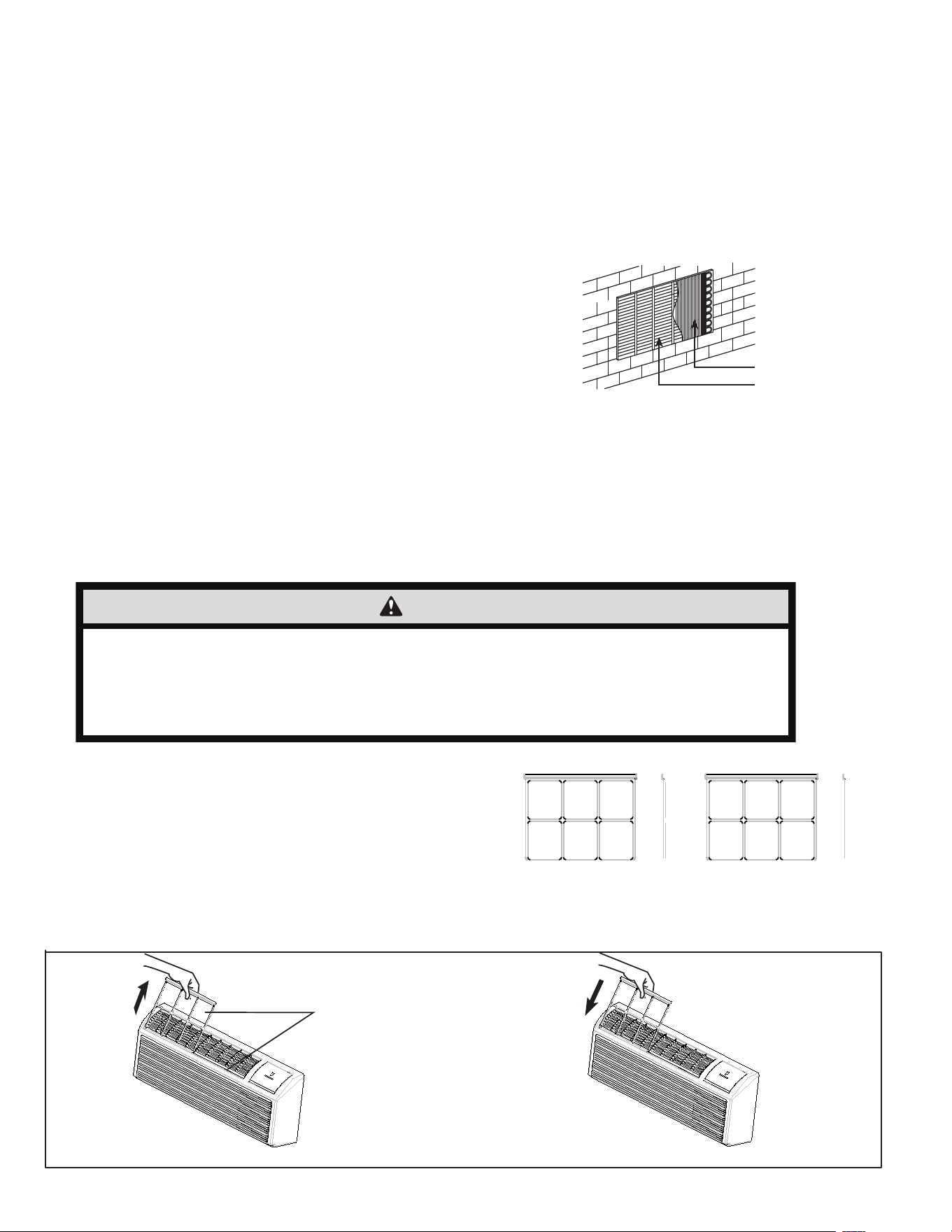
36
R . INFORMATION FOR THE OWNER
R.2 Routine Maintenance
Preventative maintenance is essential to proper unit operation,
efficiency and longevity. To ensure equipment operates properly,it
must be properly maintained. Equipment operation should be checked
and verified several times during each year. During regular unit
inspection and maintenance, follow the guidelines below:
Clean basepan and outdoor vent filter.
Clean or install new indoor-air inlet filter(s).
Clean wall sleeve and outdoor grille.
Inspect cord and receptacle.
Clean outdoor orifice and fan.
Clean indoor coil.(Never use high pressure spray on coils.)
Clean indoor fan,wire screen and front panel.
Secure electrical connections.
Ensure front panel is properly mounted and not damaged.
Ensure wall sleeve is installed properly.
Ensure heat and cool cycles operate properly.
Front panel and case
Turn unit off and disconnect power supply.
To clean, use water and a mild detergent. Do not use bleach or
abrasives. Some commercial cleaners may damage the plastic parts.
Outdoor coil
Coil on outdoor side of unit should be checked regularly. Unit will
need to be removed to inspect dirt build-up that will occur on
the inside of the coil. If clogged with dirt or soot, coil should be
professionally cleaned.
Note: never use a high-pressure spray on coil.
Clean inside and outside of outdoor coils regularly.
R.3 Qualification Of Workers
Qualification of the working personnel for maintenance, service
and repair operations should according to UL 60335-2-40、CAN/
CSA-C22.2 No. 60335-2 -40-19 Annex HH.. Every working procedure
that affects safety means shall only be carried out by competent
persons according to Annex HH. Special training additional to
usual refrigerating equipment repair procedures is required when
equipment with FLAMMABLE REFRIGERANTS is affected.
Coils
Grill
Figure R.2.1 (Outdoor Coil)
CAUTION
UNIT DAMAGE HAZARD
Failure to follow this caution may result in equipment damage or improper operation.
Do not operate unit without filters in place. If a filter becomes torn or damaged, it should be replaced immediately.
Operating without filters in place or with damaged filters will allow dirt and dust to reach indoor coil and reduce
cooling, heating,airflow and efficiency of unit. Airflow restriction may cause damage to unit.
The most important thing you can do to maintain unit efficiency is to clean
the filters at least every 30 days (or sooner depending on application).
Clogged filters reduce cooling, heating and airflow.
Keeping filters clean will:
Decrease cost of operation.
Save energy. Prevent clogged indoor coil.
Reduce risk of premature component failure.
To Clean Air Filters:
Vacuum off heavy soil.
Run water through filters.
Dry thoroughly before replacing.
Dirty Filter - Needs Cleaning Clogged Filter - Greatly Reduces
Cooling, Heating and Airflow
Figure R.2.2 (Identifying A Dirty Or Clogged Filter)
Figure R.2.3 (Replacing The Air Filter)
2 Air filters
Pull up
Push down
Replacing Air Filter
Removing Air Filter

37
R. INFORMATION FOR THE OWNER
R.3 Warranty
Friedrich Air Conditioning Co.
10001 Reunion Place, San Antonio, TX 78216
800.541.6645
www.friedrich.com
ZONEAIRE
®
• PREMIER R-32 SERIES
PACKAGED TERMINAL AIR CONDITIONERS LIMITED WARRANTY
SAVE THIS CERTIFICATE.
It gives you specific rights. You may also have other rights which may vary from state to state and province to province
In the event that your unit needs servicing, contact your nearest authorized service center. If you do not know the near
est service center, ask the company
that installed your unit or contact us - see address and telephone number above. To obtain service and/or warranty parts replacement, you must notify an
authorized FRIEDRICH Air Conditioning Co. service center, distributor, dealer, or contractor of any defect within the applicable warranty period.
When requesting service: please have the model and serial number from your unit readily available.
Unless specified otherwise herein, the following applies:
FRIEDRICH PACKAGED TERMINAL AIR CONDITIONERS AND HEAT PUMPS
LIMITED WARRANTY - TWO YEARS (Twenty-four (24) months from the date of installation). Any part found to be defective in the material or
workmanship will be repaired or replaced free of charge by our authorized service center during the normal working hours; and
LIMITED WARRANTY - THIRD THROUGH FIFTH YEAR (Sixty (60) months from the date of installation). ON THE SEALED REFRIGERATION
SYSTEM. Any part of the sealed refrigeration system that is defective in material or workmanship will be repaired or replaced free of charge (excluding
freight charges) by our authorized service center during normal working hours. The sealed refrigeration system consists of the compressor, metering
device, evaporator, condenser, reversing valve, check valve, and the interconnecting tubing.
These warranties apply only while the unit remains at the original site and only to units installed inside the continental United States,
Alaska, Hawaii, Puerto Rico, Mexico and Canada. The warranty applies only if the unit is installed and operated in accordance with the
printed instructions and in compliance with applicable local installation and building codes and good trade practices. For in ternational
warranty information, contact the Friedrich Air Condit
ioning Company - International Division.
Any defective part to be replaced must be made available to FRIEDRICH in exchange for the replacement part. Reasonable proof must be presented
to establish the date of install, otherwise the beginning date of this certificate will be considered to be our shipment date plus sixty days. Replacement
parts can be new or remanufactured. Replacement parts and labor are only warranted for any unused portion of the unit’s w arrant
y.
We will not be responsible for and the user will pay for:
1. Service calls to:
A) Instruct on the unit operation. B) Replace house fuses or correct house wiring. C) Clean or replace filters. D) Remove the un it from its
installed location when not accessible for service required. E) Correct improper installations.
2. Parts or labor provided by anyone other than an authorized service center.
3. Damage caused by:
A) Accident, abuse, negligence, misuse, riot, fire, f
lood, or acts of God. B) Operating the unit where there is a corrosive atmosphere containing
Chlorine, Fluorine, or any damaging chemicals (other than in a normal residential environment). C) Unauthorized alteration or repair of the
unit, which in turn affects its stability or performance. D) Failing to provide proper maintenance and service. E) Using an i ncorrect power
source. F) Faulty installation or application of the unit. G) Operation of the unit d
uring construction.
We shall not be liable for any incidental, consequential, or special damages or expenses in connection with any use or failur e of this unit.
We have not made and do not make any representation or warranty of fitness for a particular use or purpose and there is no implied
condition of fitness for a particular use or purpose. We make no expressed warranties except as stated in this certificate. No one is
authorized to chan
ge this certificate or to create for us any other obligation or liability in connection with this unit. Any implied warranties
shall last for one year after the original purchase date. Some states and provinces do not allow limitations on how long an implied warranty or
condition lasts, so the above limitations or other rights and remedies provided by law.
Performance of Friedrich’s Warranty obligation is limited to one of the following methods:
1. Repair of the unit
2. A refund to the customer for the prorated value of the unit based upon the remaining warranty period of the unit.
3. Providing a replacement unit of equal value
The method of fulfillment of the warranty obligation is at the sole discretion of Friedrich Air Conditioning.
In case of any questions regarding the provisions of this warranty, the English version will govern.