INSTRUCTIONS FOR USE
This IFU is only valid for the United States.

2
SUMMARY
BEFORE USE ...........................................................................................................................5
INTENDED USE .......................................................................................................................5
INTENDED USERS ...................................................................................................................5
PATIENT POPULATION ............................................................................................................6
INTENDED ENVIRONMENT ......................................................................................................6
CONTRAINDICATIONS .............................................................................................................6
RECOMMENDATIONS AND SAFETY PRECAUTIONS .................................................................6
COMPATIBILITY ......................................................................................................................7
CYBERSECURITY ....................................................................................................................7
1- GENERAL INSTRUCTIONS AND RECOMMENDATIONS ......................................................................... 7
2- NETWORK INTERFACES AND CONNECTIVITY ...................................................................................... 7
3- SOFTWARE MANAGEMENT AND UPDATES .......................................................................................... 8
4- RESPONSE TO CYBERSECURITY INCIDENTS .......................................................................................8
5- SUPPORT AND LIFECYCLE .................................................................................................................. 8
6- DECOMMISSIONING ............................................................................................................................ 8
INSTALLATION .......................................................................................................................9
1- EQUIPMENT INCLUDED IN THE BOX .................................................................................................... 9
2- STEP-BY-STEP INSTALLATION ......................................................................................................... 10
2.1- Find an appropriate area to place the device ....................................................................... 10
2.2- Check for proper water and air supply lines ......................................................................... 10
2.3- Check for a proper and safe power grid .............................................................................. 10
2.4- Be aware ............................................................................................................................ 10
2.5- Device connectivity ............................................................................................................ 10
2.5.1- Connecting / Disconnecting from the Wi-Fi ............................................................ 11
2.6- Connect air and water hoses ............................................................................................... 11
2.7- Install accessories .............................................................................................................. 12
2.8- Check the handpiece cord system connections ................................................................... 12
2.9- Fix the device ..................................................................................................................... 12
2.10- Power your device ............................................................................................................ 13
2.11- Installation of the wireless pedal ...................................................................................... 13
3- POWDER CHAMBERS ........................................................................................................................ 13
4- WATER SUPPLY AND WATER BOTTLE ................................................................................................ 14
5- AIRFLOW
®
MAX AND PERIOFLOW
®
MAX HANDPIECES ..................................................................... 14
5.1- Before use ......................................................................................................................... 14
5.2- Attaching and removing AIRFLOW
®
MAX or PERIOFLOW
®
MAX handpiece .......................... 15
5.3- Attaching and removing PERIOFLOW
®
nozzles .................................................................... 15
6- PIEZON
®
HANDPIECE AND INSTRUMENTS ........................................................................................ 15
6.1- Before use .......................................................................................................................... 15
6.2- Attaching and removing the PIEZON
®
handpiece ................................................................. 15
6.3- Attaching and removing the PIEZON
®
PI MAX instrument tip ............................................... 16
6.4- Attaching and removing PIEZON
®
instruments .................................................................... 17
DEVICE USE ..........................................................................................................................17
1- GBT SETTINGS .................................................................................................................................. 17
2- INTERFACES ..................................................................................................................................... 17
2.1- PIEZON
®
power setting ....................................................................................................... 18
2.2- AIRFLOW
®
/PERIOFLOW
®
pressure setting ........................................................................... 19
2.3- Wireless pedal battery saving ............................................................................................. 19
3- TREATMENT SEQUENCE .................................................................................................................... 19
3.1- Patient and dental professional precautions ....................................................................... 19
3.1.1- Patient preparation ................................................................................................ 19

3
3.1.2- Dental professional preparation ............................................................................. 19
3.2- Disclose ............................................................................................................................. 19
3.3- AIRFLOW
®
and PERIOFLOW
®
.............................................................................................. 20
3.3.1- Risk of emphysema ............................................................................................... 20
3.3.2- AIRFLOW
®
treatment .............................................................................................. 20
3.3.2.1- Recommendations .................................................................................... 20
3.3.2.2- Recommended position and movement ..................................................... 20
3.3.2.3- Settings .................................................................................................... 21
3.3.3- PERIOFLOW
®
treatment ........................................................................................ 21
3.3.3.1- Absolute restrictions ................................................................................. 21
3.3.3.2- Recommended use .................................................................................... 21
3.3.3.3- Settings .................................................................................................... 22
3.3.4- How to start AIRFLOW
®
/PERIOFLOW
®
treatment .................................................... 22
3.4- PIEZON
®
treatment ............................................................................................................. 22
3.4.1- Recommended use ................................................................................................ 22
3.4.2- Use and settings .................................................................................................... 23
3.4.3- How to start PIEZON
®
treatment............................................................................. 24
3.4.4- End of treatment .................................................................................................... 24
3.4.4.1- Fluoride protection .................................................................................... 24
3.4.4.2- Post-treatment recommendations............................................................. 24
4- CLEANING AND REPROCESSING ....................................................................................................... 24
4.1- Water lines cleaning ........................................................................................................... 24
4.2- Device cleaning and parts reprocessing .............................................................................. 26
5- MAINTENANCE ................................................................................................................................. 27
5.1- AIRFLOW
®
MAX/PERIOFLOW
®
MAX handpiece daily maintenance ..................................... 27
5.2- AIRFLOW
®
MAX/PERIOFLOW
®
MAX handpiece leakage ...................................................... 27
5.3- PIEZON
®
handpiece leakage ............................................................................................... 27
5.4- Light guide check & replace ............................................................................................... 27
5.5- Wear ................................................................................................................................... 28
5.6- Handpiece cord system replacement .................................................................................. 28
5.7- Monthly check .................................................................................................................... 28
5.8- Preventive maintenance and repair ..................................................................................... 29
5.9- Pairing a (new) pedal .......................................................................................................... 29
6- TROUBLESHOOTING ......................................................................................................................... 30
6.1- For AIRFLOW
®
/PERIOFLOW
®
products ................................................................................ 30
6.2- For PIEZON
®
products ......................................................................................................... 30
6.3- For the device ..................................................................................................................... 31
6.3.1- Device troubleshooting .......................................................................................... 31
6.3.2- Symbols troubleshooting ....................................................................................... 32
6.4- Contact EMS aftersales service .......................................................................................... 33
6.5- Report an adverse event ..................................................................................................... 33
SUSTAINABILITY ..................................................................................................................34
1- DISPOSAL OF WASTE ........................................................................................................................ 34
2- SUSTAINABLE DESIGN ...................................................................................................................... 34
WARRANTY ..........................................................................................................................34
TECHNICAL DATA COLLECTION AND PRIVACY POLICY .........................................................34
TECHNICAL DESCRIPTION ....................................................................................................35
SYMBOLS ............................................................................................................................. 36
ELECTROMAGNETIC COMPATIBILITY .................................................................................... 37
1- INTENDED ELECTROM AGNETIC ENVIRONMENT ................................................................................ 37
2- DEVICE PERFORMANCE AND EMC DISTURBANCE EFFECTS .............................................................. 37
3- CLINICAL IMPACTS ........................................................................................................................... 37
4- OPERATOR ACTIONS ......................................................................................................................... 37
5- COMPLIANCE LEVELS ....................................................................................................................... 37
6- PROXIMITY FIELDS FROM RF WIRELESS COMMUNICATIONS EQUIPMENT ........................................ 38
7- ELECTROMAGNETIC EMISSIONS COMPLIANCE ................................................................................. 38
RADIO EQUIPMENT COMPLIANCY ........................................................................................39
1- FCC STATEMENTS ............................................................................................................................. 39

4
1.1- RF Exposure mobile Device ................................................................................................ 39
1.2- RF Exposure portable device only for RFID ......................................................................... 39
2- ISED STATEMENTS ............................................................................................................................ 39
2.1- RF Exposure mobile Device ............................................................................................... 39
2.2- RF Exposure portable device only for RFID ......................................................................... 40
3 - WIRELESS COMMUNICATION MODULE, ONLY FOR COSTA RICA ...................................................... 40
5
BEFORE USE
Before using this device, please carefully read and follow the
recommendations of this instruction manual, the reprocessing
manual and the powder instruction manual. Please pay special
attention to the safety precautions.
Any serious incident that has occurred in relation to the device
should be reported to the manufacturer and the competent
authority of the Member State in which the user and/or patient
is established.
FOR USA AND CANADA : GROUNDING RELIABILITY CAN
ONLY BE ACHIEVED WHEN EQUIPMENT IS CONNECTED TO
AN EQUIVALENT RECEPTACLE MARKED "HOSPITAL ONLY"
OR "HOSPITAL GRADE".
DO NOT modify this device or any of its accessories or component.
Always keep these Instructions close at hand. These
Instructions are only applicable to the equipment they were
delivered with.
To prevent injury to persons or damage to property, please
observe the corresponding directives and symbols.
The Instructions for Use of the device is part of the
product documentation and is provided in electronic format.
However if you want it in hard copy, you can request one set
free of charge on our website, by telephone or in writing, and
receive it within 7 days.
The electronic Instructions for Use (eIFU) of the device is
available for download in PDF format at www.ems-instruction.
com
using the Product Name: GBT Machine AIRFLOW
®
Prophylaxis
Master or Reference: FT-300. A PDF reader is required and, in
case of need, it can be downloaded from the same web site.
We recommend that you visit our website regularly to consult
and/or download the latest version of the documentation for
your device at www.ems-instruction.com.
Please contact EMS technical support or your local EMS
representative for further information and support.
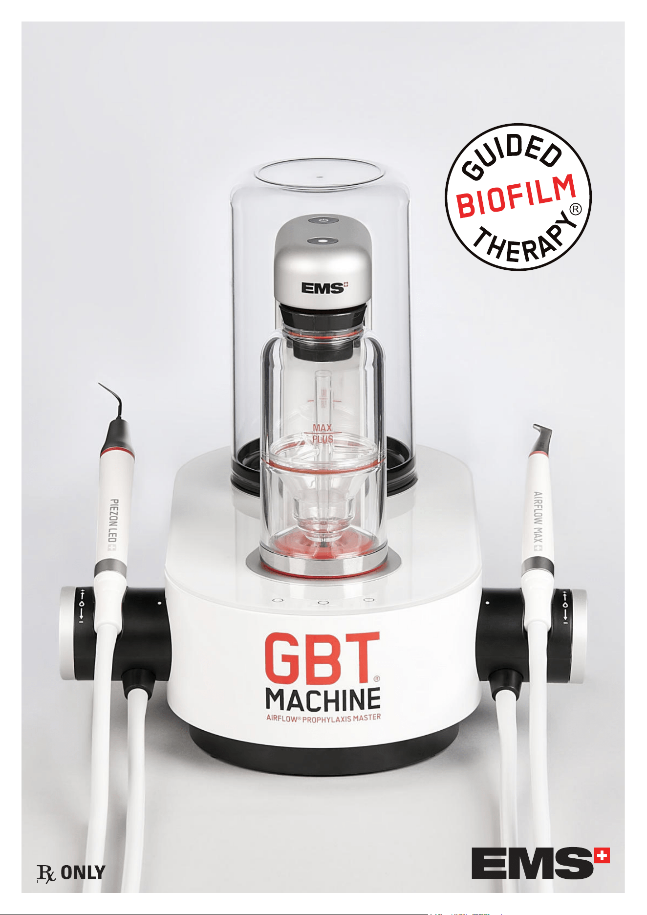
INTENDED USE
The GBT Machine AIRFLOW Prophylaxis Master combines the functions of an ultrasonic scaler and air-polishing unit within
a single chassis. The GBT Machine AIRFLOW Prophylaxis Master is intended for use in the following dental and periodontal
applications:
Removing supra and subgingival calculus deposits and stains from teeth
Periodontal pocket lavage with simultaneous ultrasonic tip movement
Scaling and root planing
The GBT Machine AIRFLOW Prophylaxis Master is intended for use in the cleaning and polishing of teeth by the projection of
water, air, and dental powders onto the tooth surface. The device removes dental plaque, soft deposits, and surface stains from
pits, grooves, interproximal spaces, or smooth surfaces of teeth.
The GBT Machine AIRFLOW Prophylaxis Master can be used for the following cleaning procedures:
plaque removal for placement of sealants
surface preparation prior to bonding/cementation of inlays, onlays, crowns and veneers
surface preparation prior to placing composite restorations
effective plaque and stain removal for orthodontic patients
cleaning prior to bonding ortho brackets
cleaning implant fixture prior to loading
stain removal for shade determination
plaque removal prior to fluoride treatment
plaque and stain removal prior to whitening procedure
The GBT Machine AIRFLOW Prophylaxis Master is also intended for use as an air-polisher in patients suffering from periodontal
disease. The GBT Machine AIRFLOW Prophylaxis Master is indicated for the non-surgical removal of subgingival plaque in
pockets up to 5 mm after initial periodontal treatment.
INTENDED USERS
Only qualified dental professionals must use this device by fully complying with their respective country’s regulations, accident
prevention measures, and strictly follow these instructions for use.
The device must be prepared and maintained only by persons who have been instructed in infection control, personal
protection and patient safety.
Improper use (e.g. due to lack of hygiene or routine maintenance), non-compliance with our instructions, or the use of
accessories and spare parts that are not approved by EMS invalidates all claims under warranty and any other claims.
No specific training other than initial professional training is required to use this medical device.
The practitioner is responsible for performing the clinical treatments and for any dangers that may arise due to a lack of skill
and/or training.
For optimal patient comfort, safety and efficiency, we suggest that you regularly follow our: SWISS DENTAL ACADEMY Training
Program. Please contact your local EMS representative for further information.
Professional product installation and product introduction by EMS certified person is highly recommended for optimal setup
and reliability.
6
PATIENT POPULATION
AIRFLOW
®
devices are intended for use on patients requiring dental treatment, including cleaning and polishing of teeth (natural
or implant) by the projection of water, air and dental powders onto the tooth surface, regardless of age or gender.
PIEZON
®
devices are intended for use on patients requiring dental treatment, including scaling (e.g. subgingival and supragingival
calculus, stains), periodontics and dental prophylaxis, regardless of age or gender.
This medical device is not intended for use on newborn (neonate) and infant (< 2 years old) patient populations.
INTENDED ENVIRONMENT
The device is intended to be used in a dental cabinet/hospital complying with each country’s regulations.
CONTRAINDICATIONS
AIRFLOW
®
Patients suffering from chronic bronchitis or asthma must not, under any circumstances, be treated with an air polishing
device. The jet of air and powder could cause respiratory difficulties.
Patients on a low salt diet must not be treated with the powder containing sodium bicarbonate. For patients on a law salt
diet use the PLUS powder without sodium bicarbonate provided by EMS.
PERIOFLOW
®
The treatment of deep periodontal pockets can cause bacteraemia. Please apply appropriate restrictions for the treatment of
risk patients:
Endocarditis
Pregnancy, breast feeding
Contagious disease
Immune deficiency (neutropenia, angranulocytosis, diabetes, hemophilia)
Patients under treatment (radiotherapy, chemotherapy, antibiotics)
The air jet and powder may cause breathing difficulties. Please apply appropriate restrictions for the treatment of risk
patients: Patients suffering from chronic bronchitis or asthma must not be treated under any circumstances with this product.
Predisposed persons may be sensitive to the powder. If allergic reactions are observed, stop using the product and
completely remove it.
The single use nozzle must be used for one single patient only. Never reuse a nozzle because treatment will be ineffective
and the risk of emphysema would increase.
The use of any other powder than the EMS powders for subgingival application would reduce the nozzle's service life. As a
result the treatment would become ineffective and would increase the risk of emphysema.
PIEZON
®
EMS recommends not to treat patients with a cardiac pacemaker or a defibrillator with this product. The functionality of these
devices may be affected by the high frequencies of the ultrasonic oscillations.
Powders
Refer to the instructions for use of the specific powder.
RECOMMENDATIONS AND SAFETY PRECAUTIONS
Only use EMS products together.
The use of any other accessories could lead to patient injury, malfunction or damage to the device.
Only use this product for the intended indications. Please refer to treatment section. Carefully read these operating
instructions before using the product. This also applies to any product used with this system. Failure to observe the operating
instructions may result in the patient or user suffering serious injury or the product being damaged.
Follow the recommendations of the "Reprocessing Instructions" manual (FB-358/NA) regarding procedure. Always
examine your AIRFLOW
®
, PERIOFLOW
®
and/or PIEZON
®
products for damage before starting treatment. Damaged product
must not be used and must be replaced. Only use original EMS spare parts and accessories.
DO NOT modify this equipment and/or any of its accessories. No modification of any part of this medical device is allowed.
DO NOT direct the AIRFLOW
®
output towards openings of the salivary ducts as this may cause temporary pain and redness.
Most dental procedures involve contaminated aerosols which could represent a risk factor. Follow the recommendations of
treatment and patient and dental professional precautions, in order to minimize the risk.
Specic recommendations for the device:
TO AVOID the risk of electric shock, this equipment must only be connected to a mains supply with protective earth/
grounding. This device uses a Class-I insulating system that requires protective earth.
Keep a minimum distance of 25 cm from any source of flammable anesthetics or oxidizing gases (such as nitrous oxide
7
(N2O) and oxygen) or in close proximity to volatile solvents (such as ether or alcohol), as an explosion may occur.
TAKE the following precautions to prevent any adverse events to the patient and/or to the user in case of electromagnetic
disturbances:
f Always refer to the information listed in the chapter “Electromagnetic Compatibility”.
f In case of a device malfunction, presumably caused by electromagnetic disturbances, first verify the cabling, and then move
any portable RF communications equipment and mobile devices placed nearby as far away as possible to rule out interference.
f Stop using the device if the electromagnetic disturbances persist and contact EMS technical support for assistance.
DO NOT open the device. There are no serviceable parts inside.
DO NOT store the powder near acids or heat sources.
DO NOT direct the jet of powder toward fillings, crowns or bridgework as this could damage these restorations.
If any serious incident occurs that is directly or indirectly related to the device, report it immediately to the manufacturer and
to the competent authority of your country and of where the patient is established (if different).
Disconnect the mains plug from electrical outlet for the purposes of maintenance, in the case of malfunction or when the
device is left unattended.
Do not leave the device unattended when the water supply is under pressure: risk of flooding. The water supply must be
turned off when the device is not in use.
The installation and connection of the unit must be carried out by a qualified technician.
EMS cannot be held liable for damage caused by noncompliance with these Warning and Safety instructions.
Use secure networks to prevent any unauthorized access to your data, which are encrypted for security purposes.
If a vulnerability is detected, contact technical support via emsrepairs@ems-na.com and disconnect the device from the
network if necessary.
COMPATIBILITY
This device is compatible with the following accessories:
AIRFLOW
®
Powders
series of DV-164, DV-165, DV-175
AIRFLOW
®
MAX Handpiece EL-308
PERIOFLOW
®
MAX Handpiece EL-354
PIEZON
®
Handpieces EN-060, EN-061
PIEZON
®
Periodontal instruments
DS-001A, DS-011A, DS-016A, DS-083A, DS-084A
PIEZON
®
PI MAX instruments
DS-010A, DT-065A
GBT Station DW-100
Applied Parts:
The following items are Medical Device Applied Parts:
f AIRFLOW
®
MAX Handpiece (EL-308)
f PERIOFLOW
®
MAX Handpiece (EL-354)
f PIEZON
®
Handpieces (EN-060, EN-061)
Applied Parts, under certain operating conditions, may exceed 41°C of temperature and reach a maximum temperature of 48°C.
CYBERSECURITY
1- GENERAL INSTRUCTIONS AND RECOMMENDATIONS
f Use secure networks to prevent any unauthorized access to your data, which are encrypted for security purposes.
f The device requires a 2.4 GHz Wi-Fi network.
f If a vulnerability is detected, contact technical support via emsrepairs@ems-na.com and disconnect the device from the
network if necessary.
2- NETWORK INTERFACES AND CONNECTIVITY
f Two jack connectors: input and output, used for connection to satellites and for maintenance by EMS technicians only.
f Wi-Fi (Radio Interface No. 1): input and output, used for cloud connection (data transfer and updates).
f LTE (Radio Interface No. 2): input and output, used for cloud connection (data transfer and updates).
f RFID (Radio Interface No. 3): input, for handpiece recognition.
f Bluetooth Low Energy (Radio Interface No. 4): input, for wireless pedal connection to the device.
Detailed technical specifications of each interface are provided in the table “Wireless Communication Module.” in the section
Technical Description.

8
3- SOFTWARE MANAGEMENT AND UPDATES
f The device automatically receives software updates via the cloud.
f The user is notified by an icon displayed on the screen.
f Only software versions digitally signed by EMS can be installed.
f Users also receive proactive notifications in case of potential malfunction or maintenance needs.
4- RESPONSE TO CYBERSECURITY INCIDENTS
f In case of a security event, EMS may interrupt the cloud connection.
f EMS customer service will contact the user if necessary.
f The device continues to operate without cloud connection.
5- SUPPORT AND LIFECYCLE
Software support is provided as long as the device is commercially available.
6- DECOMMISSIONING
f The device does not transmit or store any sensitive data.
f Therefore, no specific data deletion procedure is required upon decommissioning.
9
INSTALLATION
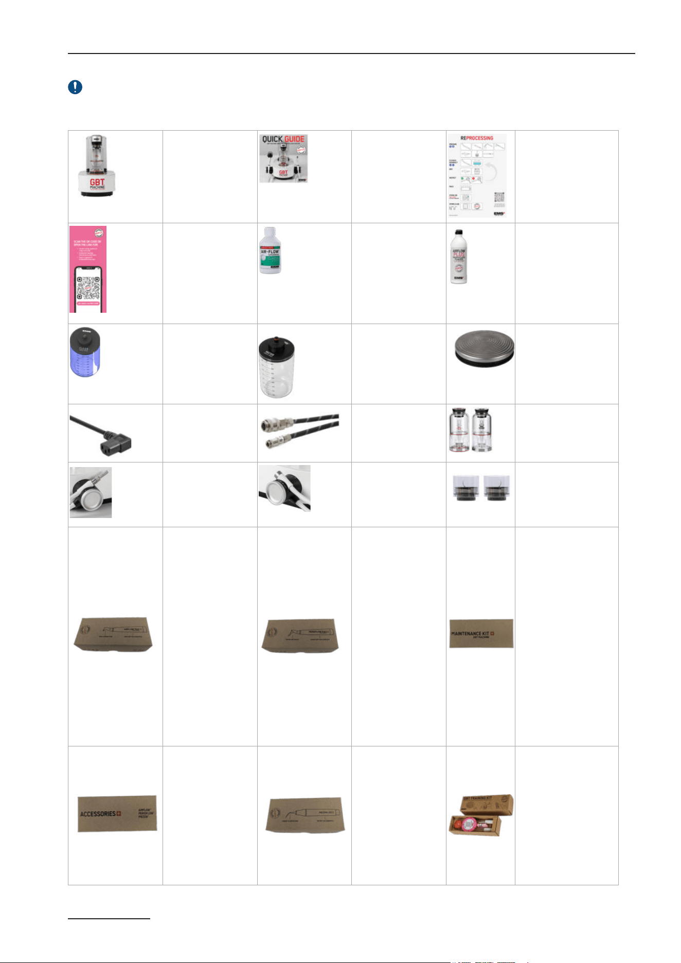
1- EQUIPMENT INCLUDED IN THE BOX
Check contents for any damage that may have occurred during transportation (device, consummable or accessory).
GBT Machine AIRFLOW
®
Prophylaxis Master CLASSIC CONFIGURATION/ GBT READY CONFIGURATION
GBT Machine
AIRFLOW
®
Prophylaxis Master
Unit with Master
Screw, water & air
filters installed
1x FT-300/*
1
Quick Guide
1x FB-1023/US
Reprocessing posters
1xFA-844
1xFA-887/EN
Customer Flyer
1xFA-888/EN
AIRFLOW
®
COMFORT
1x DV-164/MIN
AIRFLOW
®
PLUS
1x DV-165/Z
(3x DV-165/Z)
CLEANER bottle
1x EG-1000
Water bottle
2x EG-121
GBT Machine Wireless
Pedal
1x EK-1055
with 2x AA 1.5V type
lithium batteries
US Power cord
1 x CD-137
Air hose
1x EH-142
Water hose
1x EG-110
Powder chambers
1x EL-607 (Plus)
1x EL-606 (Classic)
AIRFLOW
®
MAX
Handpiece cord
(1,80m)
1x EM-1007
PIEZON
®
Handpiece cord
(1,80m)
1x EM-1009
PSL/PSR Instruments
1x FS-461
AIRFLOW
®
MAX
application
1x EL-308: AIRFLOW
®
MAX Handpiece
1xAB-470A/A (FV-083
2
):
Easy Clean
1x FS-465
(3x FS-465)
PERIOFLOW
®
application
1xEL-354: PERIOFLOW
®
MAX Handpiece
20x AB-1010 :
PERIOFLOW
®
Nozzle
1xFS-474
GBT Machine AIRFLOW
®
Prophylaxis Master
Maintenance KIT
1xEL-605 Perio cap
1xEL-655 Set
CLIP+CLEAN
2xEL-599 Air cartridge
assembly
2xEL-1207 Filters enclosure
assembly
2xAB-348/B Flat seal
ø13x1.1x2.05
3xBC-1039 O'ring
Ø1.50x1.00 VMQ Precision
1xEL-1211 AIRFLOW cord
seals set for AFPM 2.0
1xFS-600
PI MAX Introduction
Kit
1x FV-117 PI MAX
Tool
1x DS-010A/A PI MAX
Instrument
1x DT-065A/A
4x PI MAX Instrument
tips
1xFS-295#C
PIEZON
®
1PS
application
1xEN-060 : PIEZON
®
LED
Handpiece
1x DS-016A : Instrument
PS
4x AB-340 (FV-065):
Light guide
1x FS-455
(3x FS-455)
GBT training tool kit
1x FV-122
1Two versions of the device exist to meet local requirements: with LTE (FT-300/A) and without LTE (FT-300/B). This difference is not visible on the device.
2 Reference to be used for individual accessory order
10
2- STEP-BY-STEP INSTALLATION
2.1- Find an appropriate area to place the device
Place the device with the recommended GBT Station within the dental cabinet in a suitable position for your activity and
leave enough free space to allow easy handling and proper aeration.
Use of this equipment adjacent to or stacked with other equipment should be avoided because it could result in improper
operation. If such use is necessary, this equipment and the other equipment should be observed to verify that they are operating
normally.
Avoid using this device near other equipment, because it could result in improper function.
Keep a minimum of 10 cm clearance around the unit.
If not possible, verify that the device and other equipments are functioning normally.
The device must be placed on a secure and flat surface (slope < or = 5°).
2.2- Check for proper water and air supply lines
Verify that your dental cabinet has a filtered tap water source and a compressed free of oil air source using air and central water
hoses EG-110 and EH-142, respectively.
In case your cabinet water and air lines are not provided with the required hoses EG-110 and EH-142, a proper installation by
qualified personnel is required. Call EMS Service for support.
In order to prevent retro contamination, connect the hoses (cable) to EN-1717 or DVGW
3
compliant fluid sources.
2.3- Check for a proper and safe power grid
This device uses a Class-I insulating system that requires protective earth.
Plug the unit only into an FI protected mains supply (FI = Residual current protection).
For USA and Canada: connect only to a hospital-grade outlet.
Check that the rated voltage of the device is suited for the local line voltage to prevent damaging the unit, risk of fire and
electric shock.
The mains plug of the unit must be accessible at all times.
DO NOT INSTALL the device in case your dental cabinet does NOT have protective earth. If you have any concerns about
this, call EMS Service for on-site support by qualified personnel.
2.4- Be aware
The use of cables and accessories other than those supplied by EMS may negatively affect EMC performance. Use only
parts supplied by EMS.
The device uses a low power radio, 6 dBm EIRP max, Bluetooth
®
2.4 GHz, to communicate with the wireless pedal.
Interference may occur in the vicinity of this equipment. The device uses Wi-Fi 2.4 GHz and Mobile network are used for the
connectivity services.
The device uses also RFID/NFC for AIRFLOW
®
MAX and PIEZON
®
handpieces recognition.
Portable RF communications equipment (including peripherals such as antenna cables and external antennas) should be used
no closer than 30 cm (12 inches) to any part of the device, including cables. Otherwise, degradation of the performance of this
equipment could result.
2.5- Device connectivity
Your GBT Machine AIRFLOW
®
Prophylaxis Master can connect to the internet via Wi-Fi. To connect through Wi-Fi, please refer
to the instructions in the section 2.5.1- Connecting / Disconnecting from the Wi-Fi.
The GBT Machine AIRFLOW
®
Prophylaxis Master's connectivity enables continuous treatment data collection and transmission
to Electro Medical Systems. The device collects data such as PIEZON activity, AIRFLOW activity, type of handpieces used, hourly
usage, etc., to monitor the state of your device and provide access to this information through your dashboard on my.ems-
dental.com. This allows for regular software updates and proactive notifications in case of potential failures or maintenance
needs. Our goal is to help our customers and technical team improve treatment plans and device usage.
Ensure you are in an area with strong signal reception and avoid sources of electromagnetic interference. Use secure networks
to prevent unauthorized access to your data, which is encrypted for security. The device adheres to relevant data protection
regulations, such as GDPR/HIPAA. Contact customer support if you encounter any connectivity issues. If connectivity is lost,
the Wi-Fi logo on your GBT Machine AIRFLOW
®
Prophylaxis Master will turn orange. Check if the connectivity works.
3 German Technical and Scientic Association for Gas and Water
Scan for support on
installing your device
on the chair or station
11
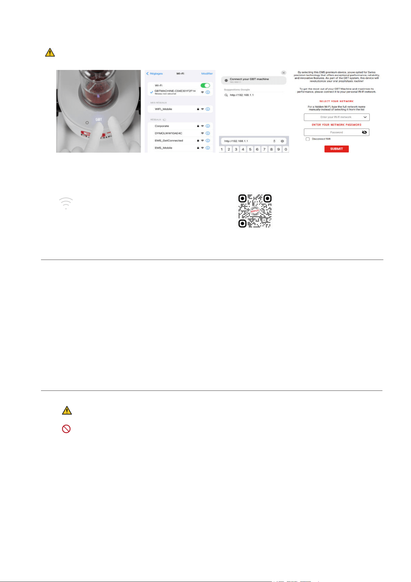
2.5.1- Connecting / Disconnecting from the Wi-Fi
Setting up the Wi-Fi connection/ disconnection is straightforward—just follow the steps below during installation:
Put your device (phone, computer, etc.) in airplane mode.
Ensure that only one user is connected to the device’s WiFi at a time.
1 2 3 4
Connect
Press simultaneously the
GBT level and high level
buttons and hold them for
2seconds.
A sonar sound will start
playing (if not, repeat the step
above) and the Wi-Fi symbol
will light up and fade several
times, connection search is
in progress.
Connect to
“GBTMACHINE-XXXX"
Wi-Fi network with your
phone.
Go on internet browser .
Tap http://192.168.1.1 in
the search bar or scan
the QR code.
If the web page does
not open, try another
browser.
Choose your Wi-Fi network you
want to connect your device
to with the drop-down list or
enter the Wi-Fi network name
manually (if hidden) and enter
your password.
If successful, the Wi-Fi logo &
the LEDs on the machine will
blink twice .
Your GBT Machine AIRFLOW
®
Prophylaxis Master is
connected to the Wi-Fi !
Disconnect
Same that above Same that above Same that above
Check the Disconnect Wi-Fi
box, then click on the Submit
button.
If you enter your login credentials incorrectly during the 4th step of your device's connection process, the sonar sound
will persist. Please turn your device off and on again, then restart the connection process from the rst step.
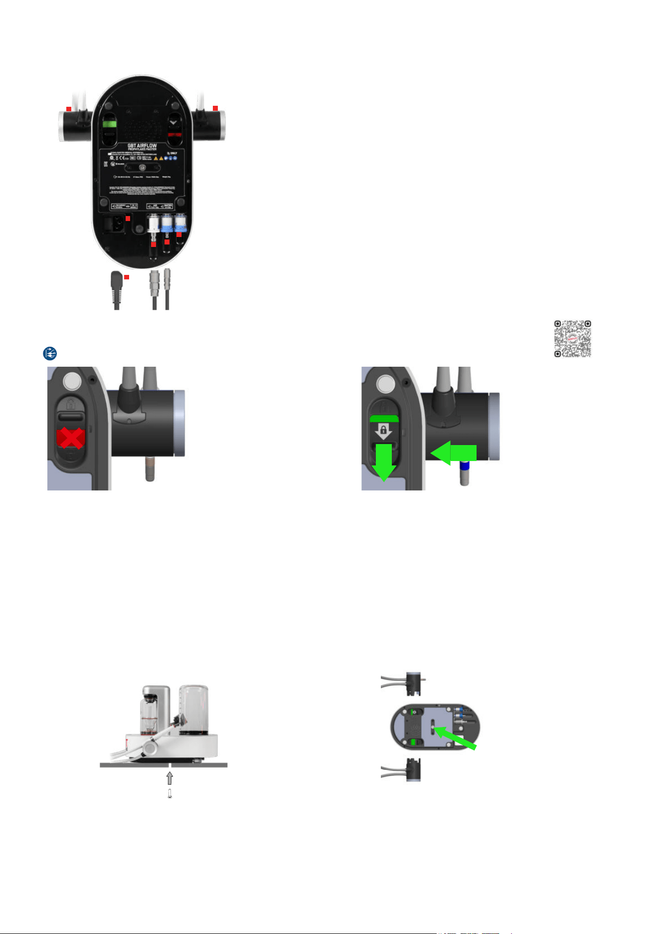
2.6- Connect air and water hoses
Turn the device over and place it upside down.
1
In the absence of the GBT Station, connect the air hose EH-142 to the
cabinet/dental unit.
Push the hose connector into the air jack firmly (it may be hard).
Pressure: 4.5 to 7 bar. Ideally 6 bar
Dry air. Max. humidity: 1.032 g/m3
Filtration: max. 1 μm
2
Connect the water hose EG-110 to the cabinet/dental unit.
To prevent retro contamination, connect the cable to an EN-1717 or
DVGW compliant fluids source.
DO NOT install the PIEZON
®
or CLEANER bottles before connecting the
air and water lines.
Drinking water
Pressure: 2 to 5 bar
Salinity: max. 0.2%
Temperature: 10°C to 30°C
12
2.7- Install accessories
Continue to keep the device upside down and disconnected from the power grid!
1
2
3
6
5
4
4
1
EH-142
Air hose – filter pre-installed
USE HARD FORCE
2
EG-110
Water hose – filter pre-installed
3
EG-121
Water bottle - filter pre-installed
For the use of bottled water, the water goes through the dedicated filter.
4
Power cord into socket
(Fuse holder in the socket)
5
EM-1007
AIRFLOW
®
MAX handpiece cord + lock actuator
USE FORCE
6
EM-1009
PIEZON
®
handpiece cord + lock actuator
USE FORCE
2.8- Check the handpiece cord system connections
First disconnect the mains plug before connecting/disconnecting any handpiece cord system.
The handpiece cord system is not fully connected.
USE FORCE to lock in.
The system is well connected & locked.
To disconnect the handpiece cord system, unlock the connection and pull at the same time.
2.9- Fix the device
Fix the device to the recommended GBT Station
Follow the quick guide delivered with your GBT Station
Fix the device to the working area other than the GBT Station
You will find a “Master Screw” provided on the bottom center of the device.
Unscrew the Master Screw first and use it to secure the device firmly to a table or onto the AL-125 device support in your cabinet
(the AL-125 part is available through our after-sales support and dealers).
Master Screw usage
Master Screw placement
Scan for support
13
Fix your device with the provided “Master Screw” in order to ensure that the unit cannot be removed without the use of a tool.
Check the position of the medical device so that it corresponds to your line of sight and the characteristics of your personal
workstation (the lighting and the distance between the user and the device). The device must remain quickly and easily
accessible at all times.
Check that the water and air lines and the power cord do not hinder physical movement.
2.10- Power your device
You can now connect the power cord to the mains grid.
Protective earth is required! Be sure your power grid has an efficient protective earth.
Settings: Voltage: 100-240 Vac - Frequency: 50 to 60 Hz - Operating current: 4 A max.
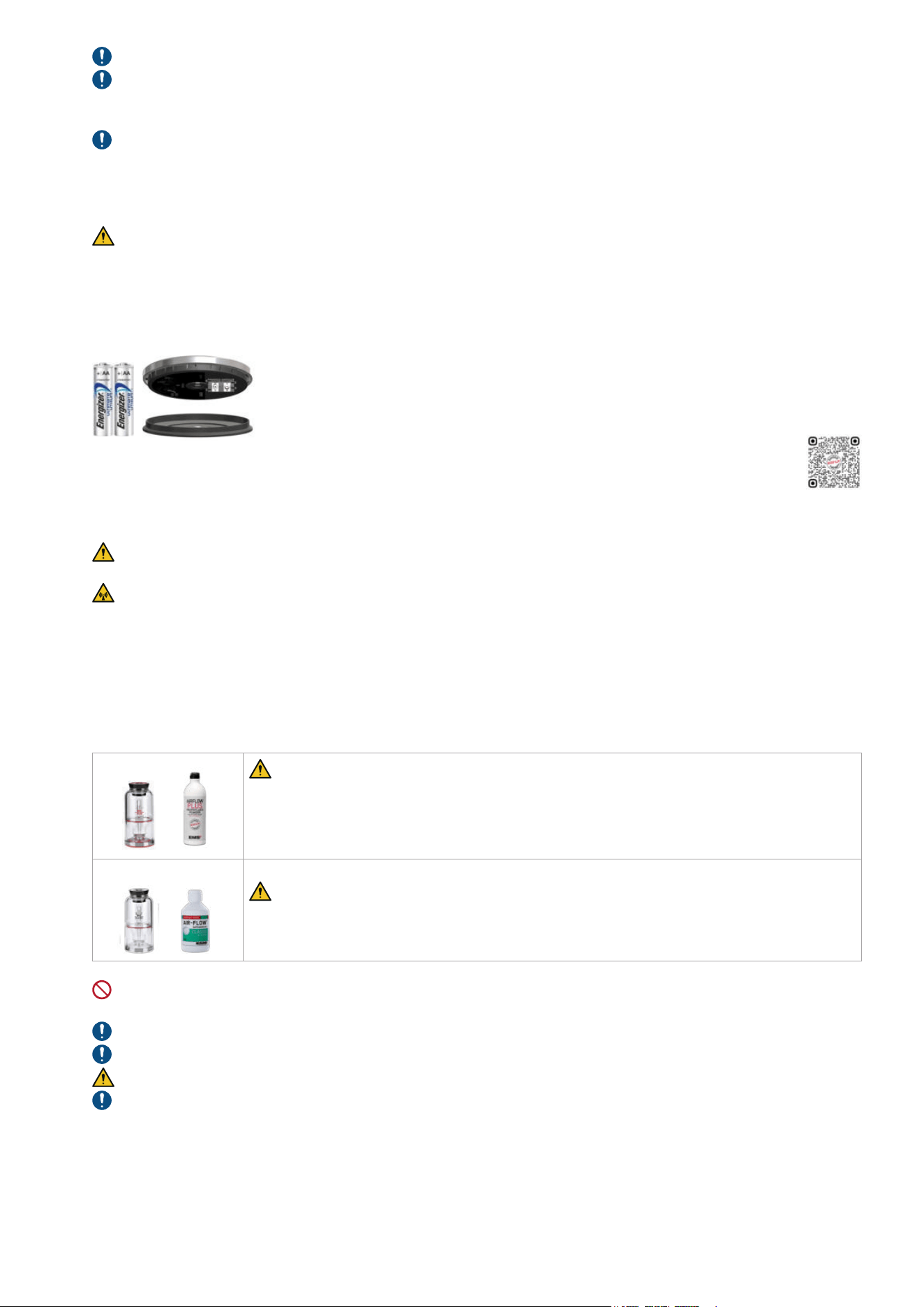
2.11- Installation of the wireless pedal
Insert two (2) AA 1.5V lithium batteries into the wireless pedal. Close the cover and operate your
device. USE ONLY LITHIUM BATTERIES.
The wireless pedal supplied with your device is already paired and ready to use (Note: A pedal can
only command one single device at a time. Pairing is maintained even if the batteries are removed).
In case you replace your pedal, you will need to pair it with your device. For instructions, please read the specific Maintenance
& Troubleshooting chapter.
Risk of fire: only use batteries that have current limiter/short-circuit and over-temperature protection (compliant to IEC
60086-4:2014 Safety of lithium batteries).
The wireless pedal uses a low power, 6 dBm EIRP max, Bluetooth
®
2.4 GHz radio, to communicate with the control unit.
Interference may occur in the vicinity of this equipment.
Portable RF communications equipment (including peripherals such as antenna cables and external antennas) should be used
no closer than 30 cm (12 inches) to any part of the device, including cables. Otherwise, degradation of the performance of this
equipment could result.
3- POWDER CHAMBERS
PLUS
The PLUS Powder chamber (with the red base) is designed for the PLUS Powder. It can be
used for supragingival and subgingival treatments.
Pressure is automatically reduced for compatibility with subgingival treatments, including
PERIOFLOW
®
treatments.
Compatible EMS Powders: series of DV-070, DV-082 (PLUS and PERIO)
CLASSIC/COMFORT
The CLASSIC/COMFORT Powder chamber (with the white base) is designed for the CLASSIC/
COMFORT Powder and should be used only for supragingival treatments.
Compatible EMS Powders: series of DV-164 (CLASSIC/COMFORT)
DO NOT sterilize the powder chambers and their caps/parts by steaming or dry thermal reprocessing. Use only ambient
temperature active disinfectant and cleaning agents.
Check powder chamber for any cracks: There should be no crack on the body.
Make sure that the powder chambers are dry.
The powder chamber is pressurized during use. Replace faulty parts immediately.
Only use powders for their own intended use. Please refer to the powder specific instructions for use.
Scan for support
14
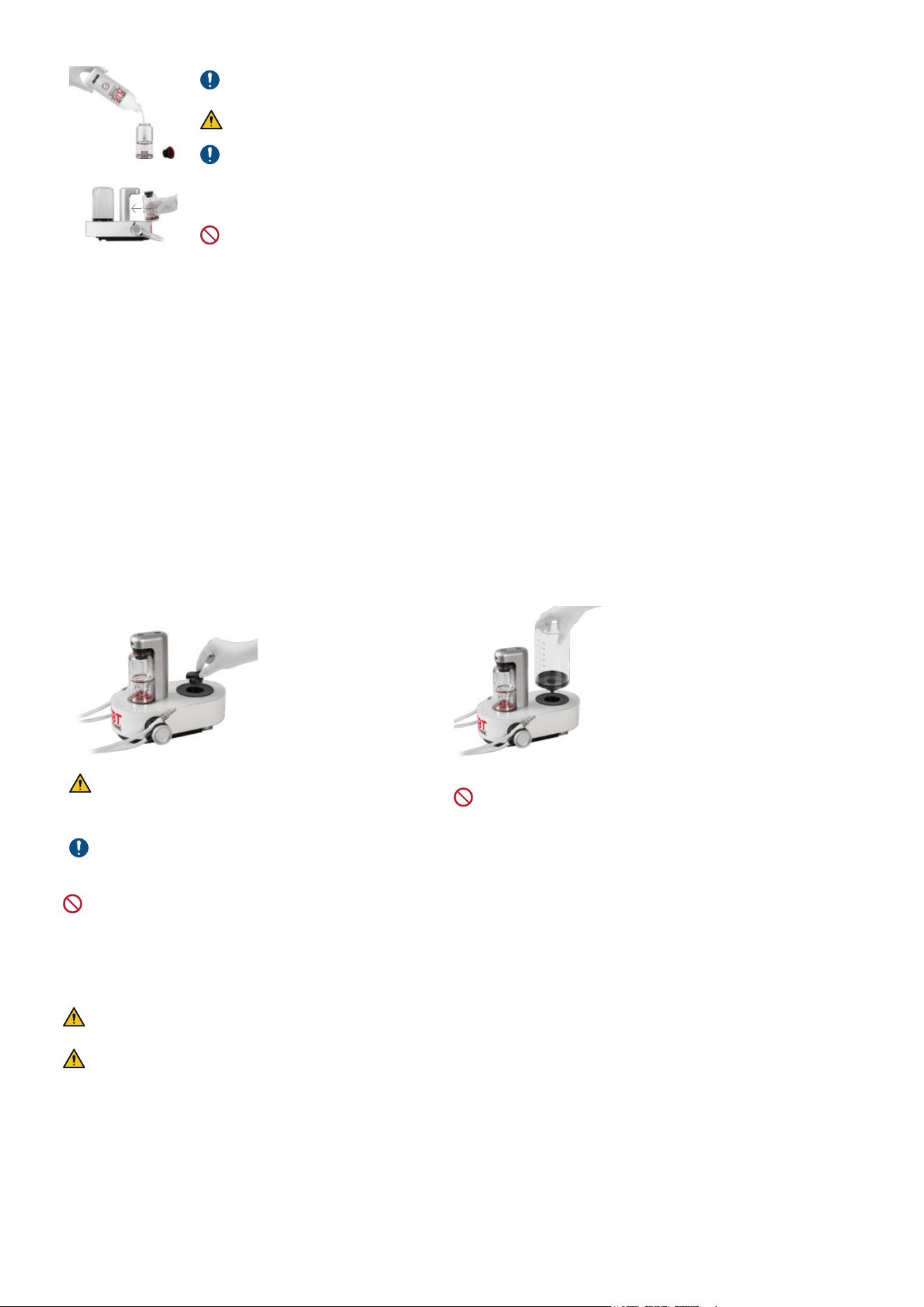
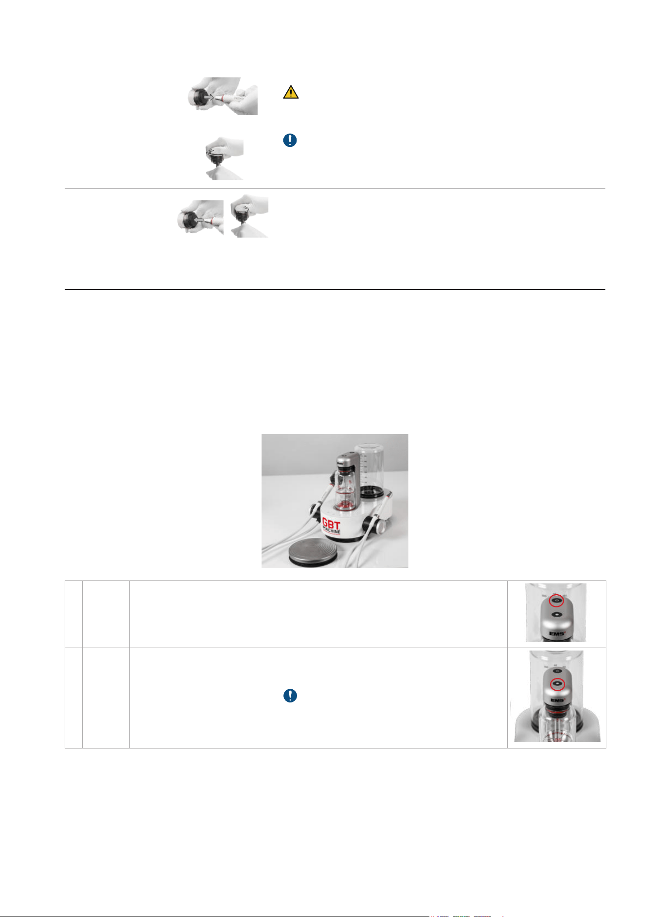
Filling the powder chambers :
By hand only: remove the powder chamber cap to refill powder up to the indicated MAX level, then
insert the cap back fully onto the bottle.
DO NOT fill the powder chamber beyond the MAX level.
Pour the powder in freely. The central tube can be fully filled without problem.
Shake the powder chamber after each filling and at least once a day.
Before pressurizing, position the powder chamber into the device. Magnetic attraction will position it
correctly.
DO NOT insert upside-down.
4- WATER SUPPLY AND WATER BOTTLE
What water should I include in my water bottle?
EMS recommends the use of:
f Filtered drinking water
f Drinkable tap water (≤500 CFU/mL bacteria)
f Distilled water
The temperature must be between 10°C and 30°C. All other liquids can damage your device and void your warranty.
How to fill your water bottles ?
f Fill both bottles each morning with filtered water or drinkable tap water (keep one as a back up to ensure uninterrupted
treatment flow).
f To remove and place the bottle, use a straight up and down movement (do not shake the bottle to avoid damages).
f At the end of every day: empty your bottles and allow to dry.
f Once a week: wash your water bottles with warm soapy water, rinse thoroughly and allow to dry.
f It is also recommended to use a bottle cleaning agent weekly.
Without Bottle:
PIEZON
®
& AIRFLOW
®
use external water supply.
With Bottle connected:
PIEZON
®
& AIRFLOW
®
use bottle liquid supply.
The CLIP+CLEAN shall be previously cleaned and
sterilized before use.
Non-sterilized CLIP+CLEAN may contaminate the device.
Place the CLIP+CLEAN into the device’s bottle receptacle
for dust protection.
Connect the water bottle
DO NOT use disinfectant solutions (e.g., chlorhexidine)
inside the water bottle during treatment.
DO NOT sterilize the water bottle and its nozzle cap by steaming or dry thermal reprocessing. Use only ambient temperature
active disinfectant and cleaning agents.
5- AIRFLOW
®
MAX AND PERIOFLOW
®
MAX HANDPIECES
5.1- Before use
EMS AIRFLOW
®
MAX and/or PERIOFLOW
®
MAX handpieces are supplied non-sterile and must be cleaned and sterilized
before first use and between patient uses. Non reprocessed products may cause bacterial or viral infections.
Follow the recommendations of the "Reprocessing Instructions" manual (FB-358/NA) regarding procedure for cleaning
and sterilizing the components, and the present-day regulations on reprocessing in effect in your country.
15
5.2- Attaching and removing AIRFLOW
®
MAX or PERIOFLOW
®
MAX handpiece
In order to ensure perfect electronic connection, the individual components must be dry.
Attaching the
AIRFLOW
®
MAX or
PERIOFLOW
®
MAX
handpiece
Connect the handpiece to the AIRFLOW
®
MAX handpiece cord.
Removing the
AIRFLOW
®
MAX or
PERIOFLOW
®
MAX
handpiece
Disconnect the handpiece from the AIRFLOW
®
MAX handpiece cord by
turning and pulling at the same time.
5.3- Attaching and removing PERIOFLOW
®
nozzles
Single-use PERIOFLOW
®
nozzle.
Cannot be reprocessed.
DO NOT use the PERIOFLOW
®
nozzle if the
package is damaged or opened.
Fully connect the PERIOFLOW
®
nozzle by
pushing on a hard surface.
Make sure the PERIOFLOW
®
nozzle is correctly
attached = fully inserted and right way
Remove the nozzle by using the PIEZON
®
instrument check tool after treatment.
Risk of injury: Always USE the PIEZON
®
instrument check tool.
DO NOT remove by hand.
6- PIEZON
®
HANDPIECE AND INSTRUMENTS
6.1- Before use
EMS PIEZON
®
products (handpieces, instruments and tools) are supplied non-sterile and must be cleaned and sterilized
before first use and between patient uses. Non reprocessed products may cause bacterial or viral infections.
Follow the recommendations of the "Reprocessing Instructions" manual (FB-358/NA) regarding procedure for cleaning
and sterilizing the components, and the present-day regulations on reprocessing in effect in your country.
Check regularly instrument length with the PIEZON
®
instrument check tool.
If PIEZON
®
instrument extremity reaches or is shorter than the limit indicated by the GBT Logo, it can have excessive and
uncontrolled vibrations. Replace the tip.
6.2- Attaching and removing the PIEZON
®
handpiece
In order to ensure perfect electronic connection, the individual components must be dry.
Attaching the
PIEZON
®
handpiece
Connect the PIEZON
®
handpiece to the PIEZON
®
handpiece cord.
Removing the
PIEZON
®
handpiece
Disconnect the PIEZON
®
handpiece from the PIEZON
®
handpiece cord.
Scan for support
16
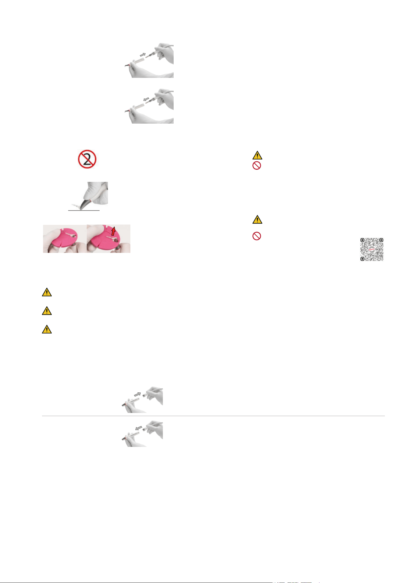
6.3- Attaching and removing the PIEZON
®
PI MAX instrument tip
In order to ensure perfect electronic connection, the individual components must be dry.
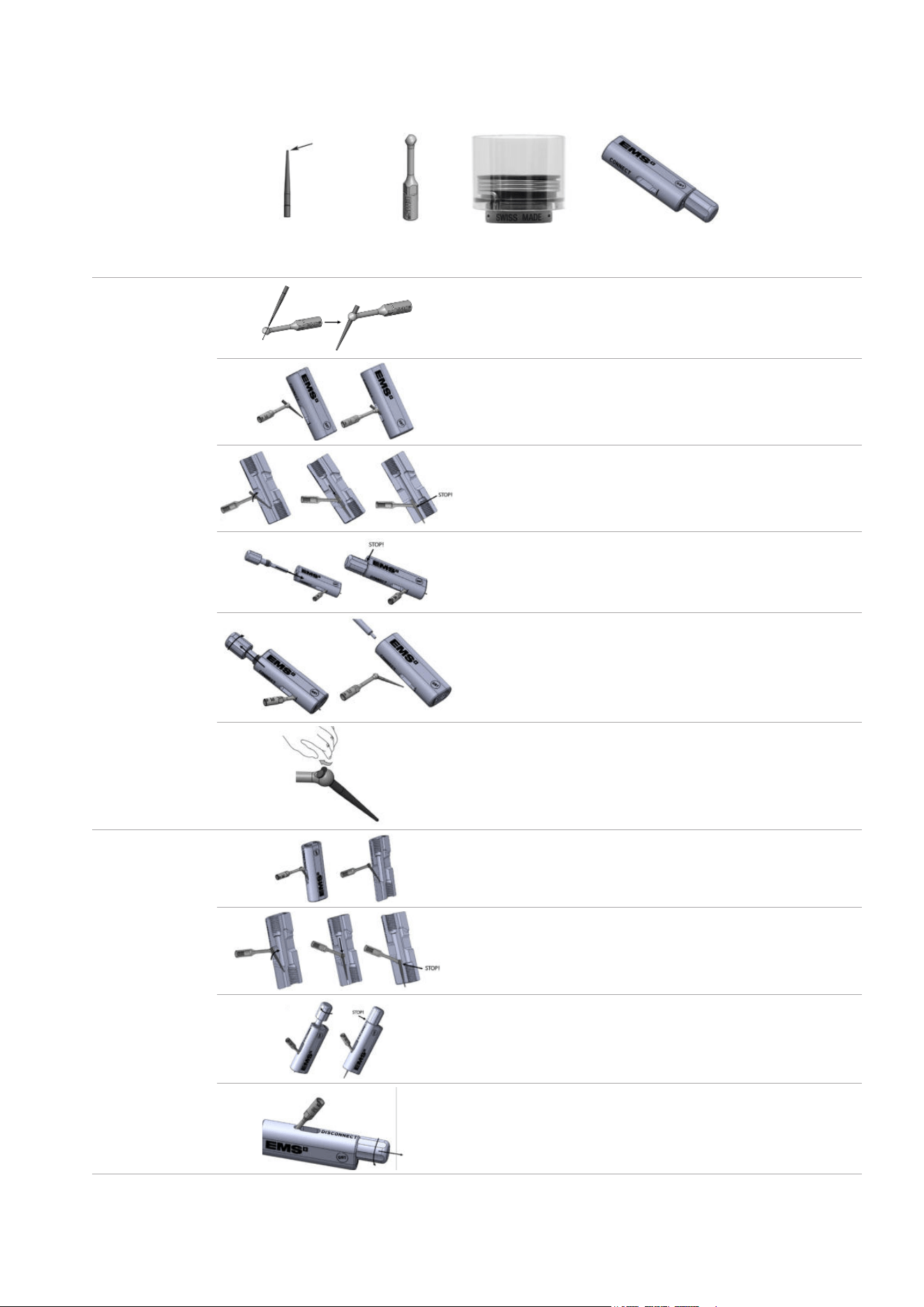
The PIEZON
®
PI MAX instrument is composed of:
PI MAX Instrument Tip
Working tip
PI MAX Holder
Combitorque
®
PI MAX Instrument Tool
Attaching the
PIEZON
®
PI MAX
instrument tip
Pre-Insert the TIP in the HOLDER.
Take the PI TOOL. Remove the SCREW from the PI TOOL base.
Gently insert the TIP in the PI TOOL feature marked CONNECT.
Gently tilt the PI in the PI TOOL base. Slide it down to STOP.
Insert the SCREW and screw until the head of the screw is in
contact with the body of the tool.
Unscrew the SCREW.
Gently remove the PIEZON
®
PI MAX with new TIP inserted.
If needed, remove the small plastic chip with your finger.
Removing the
PIEZON
®
PI MAX
instrument tip
Take the PI TOOL. Remove the SCREW from the PI TOOL base.
Gently insert the TIP in the PI TOOL feature marked DISCONNECT.
Gently tilt the PI in the PI TOOL base. Slide it down to STOP.
Insert the SCREW and screw until the head of the screw is in
contact with the body of the tool.
The TIP is disconnected from the HOLDER. Take it with fingers.
Unscrew the SCREW and get back the HOLDER.
17
6.4- Attaching and removing PIEZON
®
instruments
In order to ensure perfect electronic connection, the individual components must be dry.
Attaching the
PIEZON
®
instrument
Mount the PIEZON
®
instrument using the CombiTorque
®
.
Only use the CombiTorque
®
to tighten the PIEZON
®
instrument on the
PIEZON
®
handpiece to the correct torque to avoid instrument unscrewing
or breaking
Once the instrument is screwed all the way in, give an extra quarter of a
turn to obtain the required torque and remove the CombiTorque
®
.
Gently remove the CombiTorque
®
following the shape of the PIEZON
®
instrument.
Removing the
PIEZON
®
instrument
Gently place the CombiTorque
®
following the shape of the PIEZON
®
instrument. Unscrew it counterclockwise.
DEVICE USE
1- GBT SETTINGS
Guided Biofilm Therapy (GBT) is a standardized protocol to remove biofilm, stains and calculus from natural teeth,
restorations and implants. The default GBT settings set at medium power and high water levels for both PIEZON and AIRFLOW
technologies - are one of the innovations of the GBT Machine AIRFLOW
®
Prophylaxis Master, allowing it to:
Ensure Consistency: Easy implementation.
Improve Ergonomics: For better clinician experience
The GBT settings are designed to benefit both patients and clinicians. For more understanding, please refer to the Swiss Dental
Academy (SDA).
2- INTERFACES
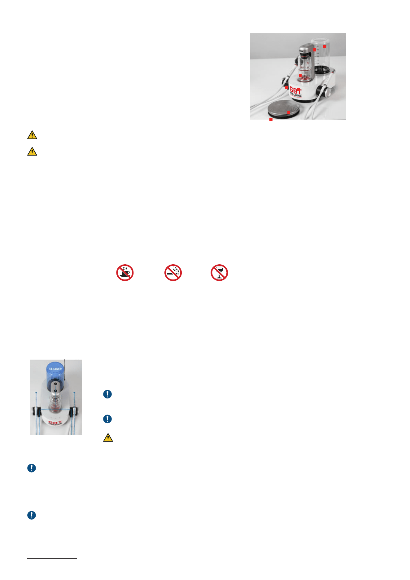
1
ON/
OFF-
Standby
mode
ON: the device goes into operating mode.
OFF: the device reverts back to standby.
After 1 hour of inactivity, the device switches automatically to standby mode, and the
powder chamber depressurizes automatically.
2
Powder
chamber
To pressurize or depressurize the powder chamber, use the button on the caliper.
A white light will turn on to indicate the powder chamber is pressurized. When
depressurizing, the AIRFLOW
®
MAX handpiece cord will automatically purge, and the
white light will turn off when done.
Depressurizing the powder chamber can take
up to 10 seconds. When not in use, keep the AIRFLOW
®
MAX handpiece in its holder
with the nozzle facing down to prevent upward spraying of air and powder.
If the powder chamber is not pressurized, the device will operate in water-only mode.
18
3
Power
setting
First lift the handpiece from his holder.
Press the touch buttons to adjust AIRFLOW
®
and PIEZON
®
power.
White LED lights indicate your selection:
• Low level: Left LED light
• GBT power setting: Left and central LED lights
• High level: Left, central and right LED lights
By default, each time you put AIRFLOW
®
MAX or PIEZON
®
handpiece back on the device, it goes back to GBT
power setting.
GBT HIGHLOW
4
Water
setting
First lift the handpiece from his holder.
Adjust PIEZON
®
and AIRFLOW
®
water flow rate by turning the control knob on the
handpiece cord system (touch buttons does not work for water setting):
• AIRFLOW
®
: Right control knob
• PIEZON
®
: Left control knob
Blue LED lights indicate your selection:
• Low level: Left LED light
• Medium level: Left and central LED lights
• GBT water setting: Left, central and right LED lights
By default, each time you put AIRFLOW
®
MAX or PIEZON
®
handpiece back on the
device, it goes back to GBT water setting.
GBT HIGHLOW
5
Pedal
(normal)
Press the edge of the foot pedal for normal operation.
At least one handpiece cord system is required to operate the device.
The foot pedal cannot be activated when both handpieces are placed in their holders,
and when the device is not in use.
6
Pedal
BOOST
Using BOOST provides a convenient way of temporarily increasing the power/pressure
within the current setting (Low, GBT, High). BOOST is activated by pressing hard on
the center of the wireless pedal with the heel up and deactivated by returning the foot
to normal pedal activation (heel down). See Sections 2.1 and 2.2 below for the BOOST
power and pressure levels.
2.1- PIEZON
®
power setting
The unit is equipped with a technology which provides a dynamic power regulation in
function according to the load applied to the instrument.
The following table shows the power as per user power setting:
Power settings Low GBT High
Max output power (W) 1.5 3.4 4.4
BOOST (W) 2.4 - 4.8 3.4 - 6.8 4 - 8
Scan for support
AIRFLOW
PIEZON
NORMAL Press gently the border
BOOST
Press hard the center
19
2.2- AIRFLOW
®
/PERIOFLOW
®
pressure setting
Both the PLUS and CLASSIC/COMFORT powder chambers have an integrated dynamic
pressure regulator that automatically set the optimal pressure range for the selected powder
chamber and related powder type as detailed in chapter “Powder Chambers”.
The following table shows the static and approximate dynamic pressures
4
as per selected powder chamber and user power
setting:
Pressure settings Low GBT High
Static (Bar) 2.3 2.65 3.15
AIRFLOW
®
PLUS dynamic (Bar) 1.6 1.95 2.45
BOOST AIRFLOW
®
PLUS (Bar) 2.45 2.8 3.0
Pressure settings Low GBT High
PERIOFLOW
®
dynamic (Bar) 2.0 2.3 2.7
2.3- Wireless pedal battery saving
Each time the wireless pedal is released, it enters into a low power mode. Even if unused for long, it is not required to remove
the batteries.
To avoid an involuntary depletion of the wireless pedal batteries, in case the pedal remains pressed without interruption for
10minutes, it will automatically enter into switch-off mode.
To resume from the switch-off mode, it is required to first release the wireless pedal and then power cycle the device (switch
off for 30s and then power on again).
3- TREATMENT SEQUENCE
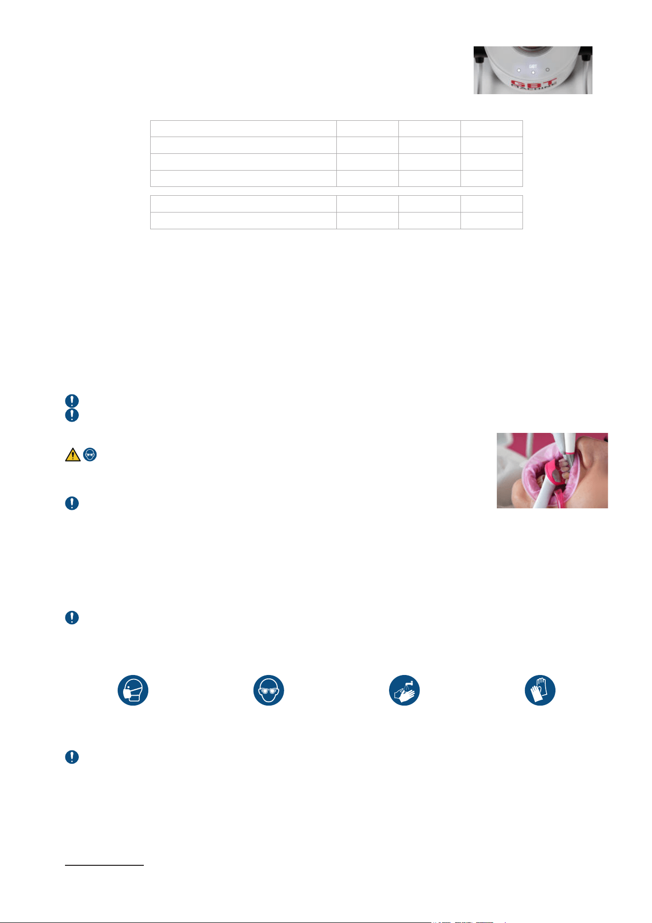
3.1- Patient and dental professional precautions
For your protection and the protection of your patient, start by gargling patient mouth with antimicrobial mouth rinse.
Always refer to treatment recomendations manual (FA-892/US) before using the device.
3.1.1- Patient preparation
Eye protection is mandatory.
It is also recommended to remove the patient‘s glasses and optical lenses.
GBT VISIGATE for lip and cheek retractor protection is recommended for clinician convenient.
Not available in the device configuration.
GBT VISIGATE
®
is an auxiliary aid for clinical use which allows the working field to be accessed with ease. It provides
retraction of lips and cheeks during dental treatment, offers the clinician increased visibility and accessibility and facilitates
saliva and moisture control in the oral cavity.
The device is placed in the mouth by the clinician before treatment to retract the lips and cheeks, then removed after the
procedure.
For detailed instructions on use and contraindications, please refer to the GBT VISIGATE
®
Instructions for Use
If PERIOFLOW
®
treatment has to be performed, radiographs is mandatory to correlate clinical probing depth
3.1.2- Dental professional preparation
Protect yourself with the following measures:
Wear protective mask Wear protective glasses Wash your hands Wear protective gloves
Additional personal protective equipment can be used.
GBT FLOWCONTROL
®
and saliva ejector are mandatory. They evacuate the air/powder mixture deviated by the treated
tooth. Study
5
on aerosol management shows that if AIRFLOW
®
is used as recommended, the risk is negligeable for the clinician.
3.2- Disclose
Use the Biofilm Discloser to reveal biofilm on all hard tissues. Remove excess disclosing using AIRFLOW
®
MAX handpiece
without pressurizing the powder chamber (water-only mode) and with High level water, with the GBT Flowcontrol. Please refer
to the instruction provided with the product.
4 Dynamic pressures depend on handpiece and powder type too. The listed pressures are for information purpose and referring to the commonly used EL-308
AIRFLOW
®
MAX handpiece with DV-082 powder.
5 Aerosols in Dentistry: The Bacterial Contamination of the Room Air During an AIRFLOW
®
Treatment. Marcel Donnet, Klaus-Dieter Bastendorf, Magda Mensi, Adrian
Lussi. www.ZM.ONLINE.de 12/2020
EMS Nyon
20
3.3- AIRFLOW
®
and PERIOFLOW
®
Please refer to the section "CONTRAINDICATIONS" for information regarding AIRFLOW
®
and PERIOFLOW
®
.
3.3.1- Risk of emphysema
To limit the risk, always follow contraindications, recommendations and detailed instructions.
Subcutaneous emphysema occurs as a result of an abnormal introduction or presence of air or gas into tissue or tissue spaces.
It has been recognized and documented as a complicating factor of any dental procedure where pressurized air has been used.
Expeditious diagnosis and management of subcutaneous emphysema are important to facilitate recovery.
Clinical signs of emphysema:
f Crackling of mucosa upon pressure (subcutaneous crepitation), pain, swelling, tenderness and discomfort.
f Often accompanied by facial or neck swelling.
In case of emphysema :
f Immediately stop the procedure
f Determine the extension and location
f Observe the patient for 30min and if the emphysema is not extended outside the oral cavity, compress to reduce it (from the
apex).
f Patient may need antibiotics and anti-inflammatory (according to patient health), in case the dental professional cannot
prescribe antibiotics, kindly refer the patient to a physician or a hospital for the recommended medicine.
f If the emphysema extends outside the oral cavity, particularly if there is a compression or constriction of airways or patient
has difficulties to breath, call the emergency service
3.3.2- AIRFLOW
®
treatment
3.3.2.1- Recommendations
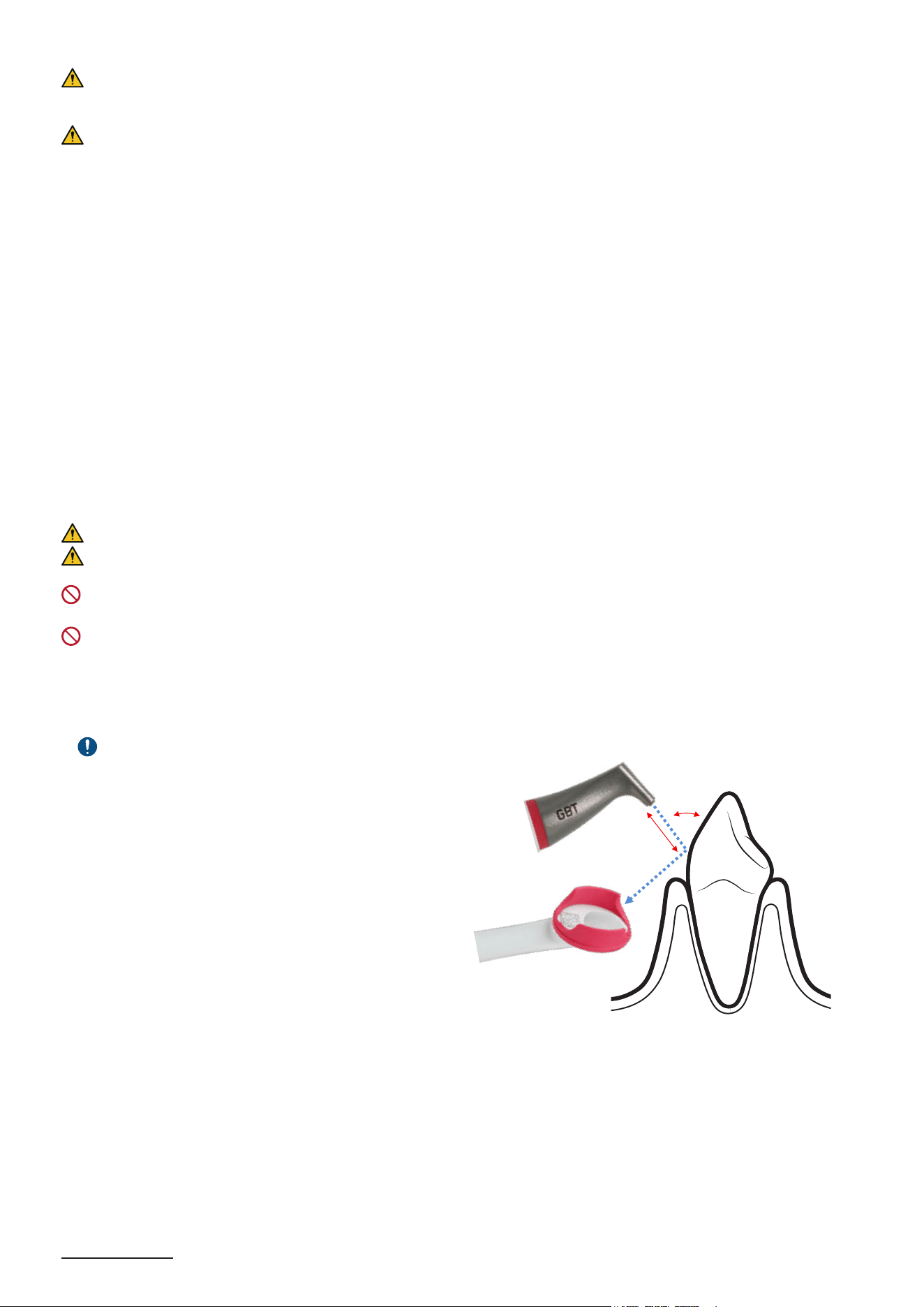
Avoid touching hard and soft tissues with the handpiece directly. Keep a minimum distance of 1-2 mm.
When you remove your foot from the pedal, the air/powder jet continues for a few more seconds, so continue to use the
GBT FLOWCONTROL
®
.
DO NOT use AIRFLOW
®
products on patient with uncontrolled acute bronchitis/asthma or upper respiratory tract disease
or infection during treatment.
DO NOT use AIRFLOW
®
products in specific sites :
- Sites with suppuration on probing, including open wounds
3.3.2.2- Recommended position and movement
Aerosol management:
f
Use GBT FLOWCONTROL
®
f Direct the jet projections towards the cannula
For optimal efciency:
Angle
f Avoid using the AIRFLOW
®
MAX handpiece at 90°
f Continuously adapt the angle while working
f Maximal range of usage is between 15°-80°
6
Distance
f General rule: With AIRFLOW
®
MAX, work closer!
f Keep the handpiece at 3 to 5 mm
6
during work
f In case of heavy stains, keep the handpiece at max 2mm
6
Movement
f Make continuous semi-circular movement
f Small smileys mesial to distal
f Never hold the handpiece stationary
6 Settings are for AIRFLOW
®
MAX handpiece. For the other AIRFLOW
®
handpieces, the angle must be between 30° to 60° and the distance between 3 and 5 mm.
15° to 80°
6
2-5mm
6
21
3.3.2.3- Settings
Power setting
7
:
Water setting:
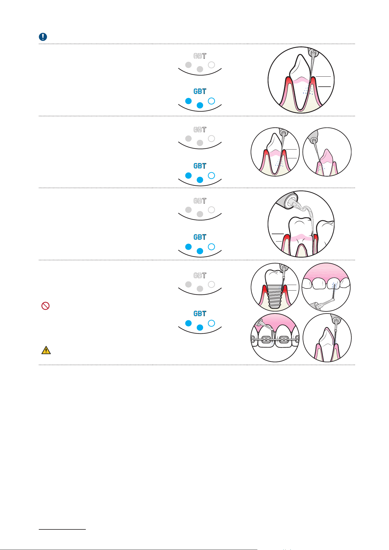
3.3.3- PERIOFLOW
®
treatment
3.3.3.1- Absolute restrictions
Please refer to the section "CONTRAINDICATIONS" for information regarding PERIOFLOW
®
.
3.3.3.2- Recommended use
f Only use by trained and qualified personnel.
f Correlate clinical probing pocket depth with radiographs before using the
PERIOFLOW
®
nozzle.
f Always check the patency of the PERIOFLOW
®
nozzle before and during use.
f Single use per patient. DO NOT use the same PERIOFLOW
®
nozzle in more
than 1 patient, PERIOFLOW
®
nozzle cannot be sterilized or re-used.
f Use the PERIOFLOW
®
nozzle between 5-10 secs per site depending on the
probing depth.
f If treating multiple sites in 1 patient, check if the tip of the PERIOFLOW
®
nozzle is not bent and the quality of the PERIOFLOW
®
nozzle has not changed.
f After approx. 20 sites, change the PERIOFLOW
®
nozzle.
f In natural teeth, after a 6-point pocket charting, the PERIOFLOW
®
nozzle is to
be used only in sites where probing depths exceed 4 mm.
f Use your finger and thumb to compress the site.
f Never push or force the PERIOFLOW
®
nozzle into the pocket even if the
depth is > 4 mm.
f Use it in a vertical overlapping, repetitive movement. The PERIOFLOW
®
nozzle must be inside the pocket during the entire cleaning process.
f Around dental implants, use the PERIOFLOW
®
nozzle in buccal, lingual,
mesial and distal sites - all sites in general.
PREFERABLY USE the PERIOFLOW
®
nozzle with tabletop devices.
ONLY USE AIRFLOW
®
PLUS or PERIO for subgingival application with
PERIOFLOW
®
nozzle.
Vertical movements
7 Power adjustment depends on the practitioner’s perception and experience.
GBT
A
B
O
V
E
C
E
M
E
N
T
O
-
E
N
A
M
E
L
J
U
N
C
T
I
O
N
GBT
A
R
O
U
N
D
B
R
A
C
K
E
T
S
E
X
P
O
S
E
D
D
E
N
T
I
N
E
GBT
I
N
T
E
R
D
E
N
T
A
L
GBT
O
N
P
R
I
M
A
R
Y
T
E
E
T
H
O
N
R
E
S
T
O
R
A
T
I
O
N
S
I
N
P
I
T
S
A
N
D
F
I
S
S
U
R
E
S
GBT
S
U
B
G
I
N
G
I
V
A
L
4MM
GBT
A
R
O
U
N
D
I
M
P
L
A
N
T
S
4MM
22
3.3.3.3- Settings
This is dependant on which PERIOFLOW
®
handpiece being used
Power setting for NEW
PERIOFLOW
®
handpiece
(with RFID)
8
:
Power setting for OLD
PERIOFLOW
®
handpiece (with no
RFID):
I
N
P
E
R
I
O
D
O
N
T
A
L
P
O
C
K
E
T
S
4MM
4MM
I
N
P
E
R
I
-
I
M
P
L
A
N
T
P
O
C
K
E
T
S
I
N
R
O
O
T
F
U
R
C
A
T
I
O
N
S
Water setting for NEW
PERIOFLOW
®
handpiece
(with RFID):
Water setting for OLD
PERIOFLOW
®
handpiece (with no
RFID):
3.3.4- How to start AIRFLOW
®
/PERIOFLOW
®
treatment
1 Connect the WATER bottle (if required).
2 Switch ON the device
3 Position the PLUS powder chamber, filled with PLUS powder, into the
device to start GBT treatment
4 Pressurize the chamber
5 Take the AIRFLOW
®
MAX handpiece or PERIOFLOW
®
MAX handpiece
and nozzle
6 Use the default power GBT settings [or increase the power]
7 Use the default water GBT settings
8 Press the pedal to start treatment.
9 [Step hard on the center of the pedal for BOOST]
10 Release the pedal to stop treatment
11 Put the handpiece back into its holder
*
*
Settings come back to default GBT settings
12 Depressurize the powder chamber before removing the AIRFLOW
®
MAX handpiece for sterilization
1
6
7
2
3
4
5
8
9
Treatment does not stop immediately. Beware there is a small delay between the release of the pedal and the effective stop
of the treatment (approximately 0.2 second). Make sure to never point the PERIOFLOW
®
nozzle toward the patient, during and
after operation.
Risk of patient injury. If you are not trained on a specific treatment, do not execute it. Always get trained before executing
new treatments.
3.4- PIEZON
®
treatment
3.4.1- Recommended use
Please refer to the section "CONTRAINDICATIONS" for information regarding PIEZON
®
.
PIEZON
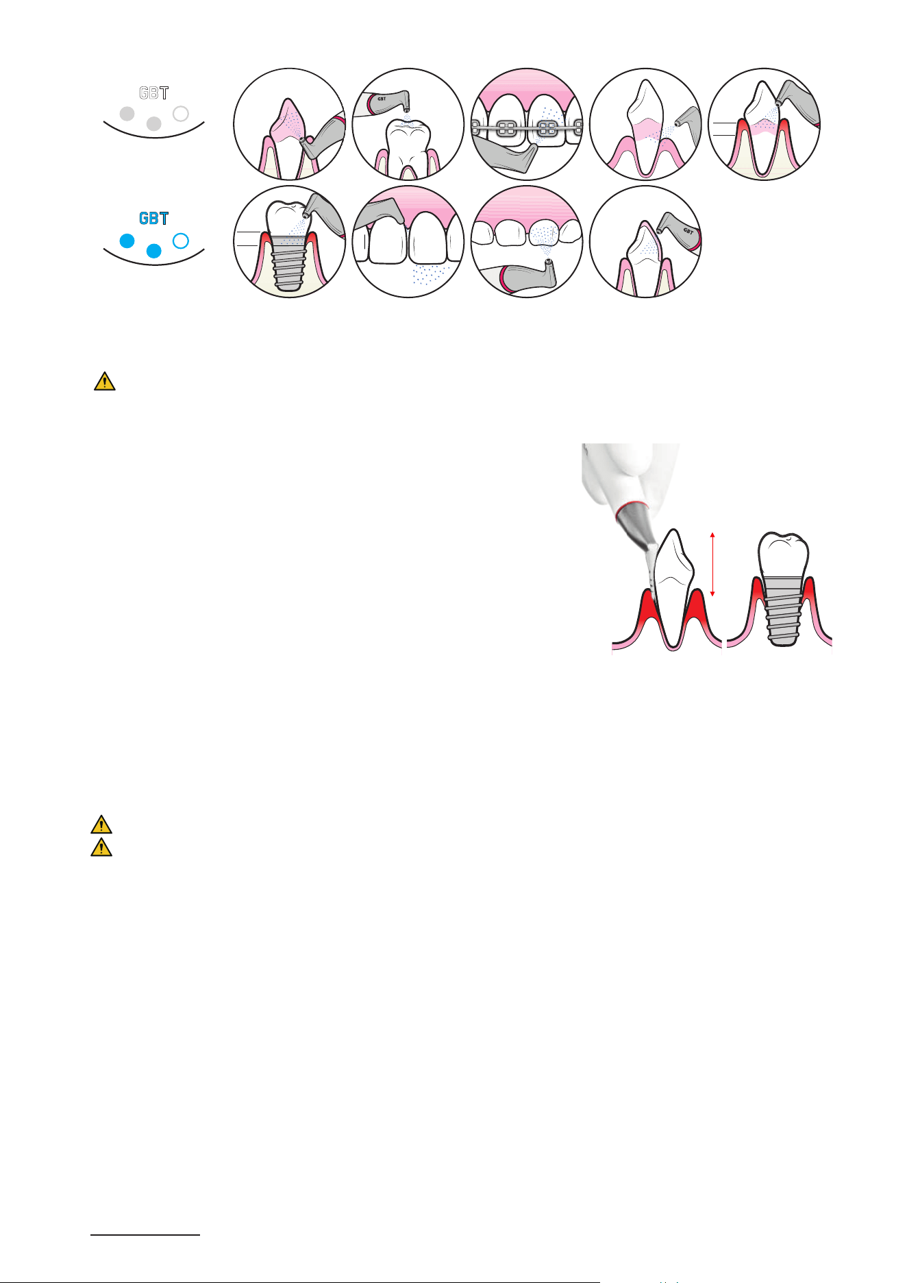
®
instruments vibrate in a controlled back-and-forth oscillation. During treatment, always hold the instrument parallel
to the tooth surface adapting the lateral side of the instrument.
DO NOT direct the instrument straight to the enamel surface. Never point the tip of the instrument to the tooth surface.
During PIEZON
®
treatment, only the last 2mm of the PIEZON instrument, should be in contact with soft tissues in the patient
mouth. The metallic part of the PIEZON
®
handpiece can heat up during a long period of treatment if recommendations are not
followed.
On metal, ceramic restorations, and on prosthetics, ONLY use the PIEZON
®
PI MAX instrument.
Listen for a noise change:
f For PIEZON
®
Instruments: a suspicious noise during contactless activation may be a sign of possible damage to the system
or improper screwing of the instrument. In this case, check the correct screwing with the CombiTorque
®
, then the condition of
the instrument. If in doubt, contact the support service.
f For the PIEZON
®
Handpiece: it could occur when the instrument is activated in order to detect a possible loosening of the
instrument in the handpiece.
8 Power adjustment depends on the practitioner’s perception and experience. The PERIOFLOW
®
MAX handpiece does not have a boost function.
23
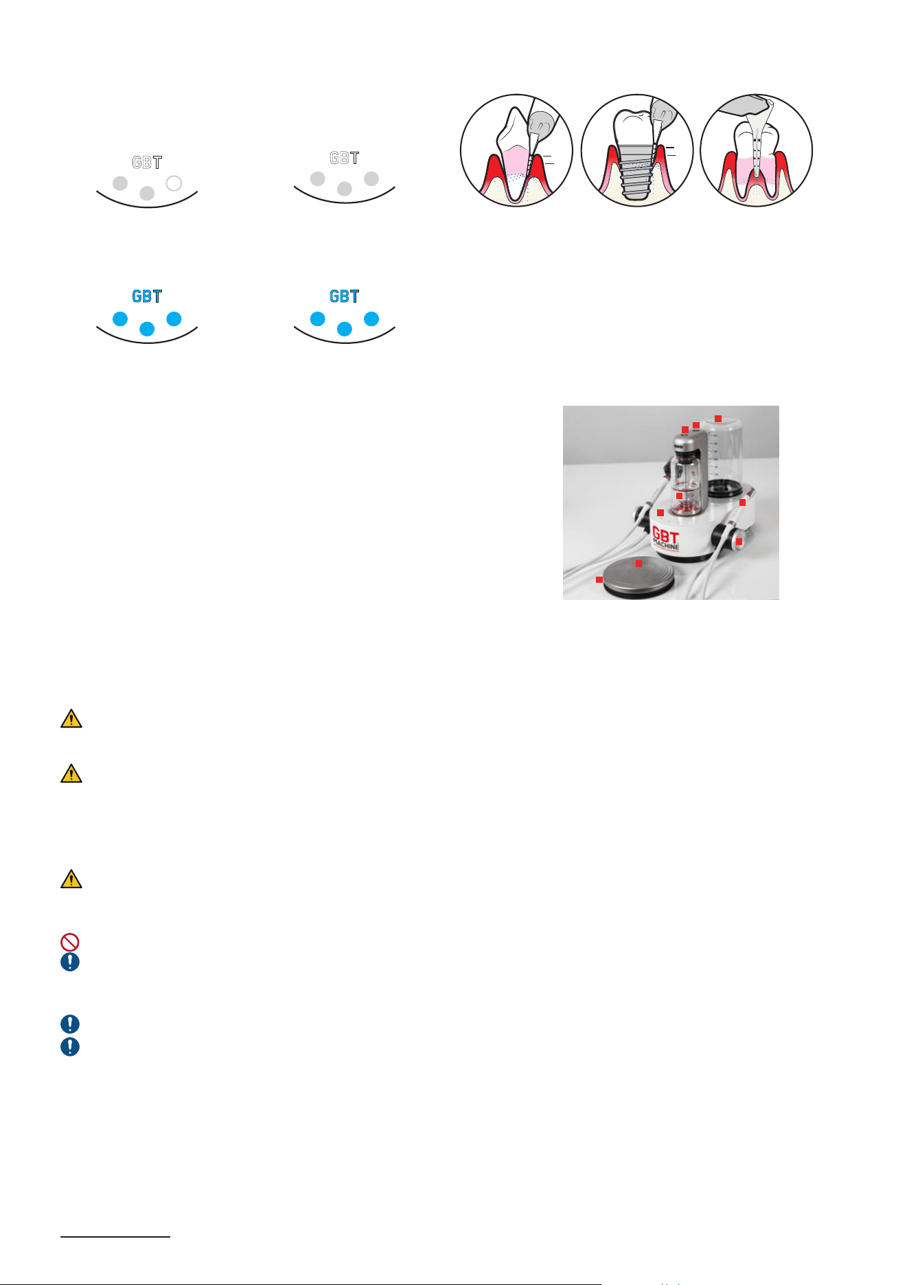
3.4.2- Use and settings
Always start PIEZON
®
treatment with default GBT setting and use the BOOST function as necessary (hard calculus).
9
PIEZON
®
Instrument P
Hard calculus; subgingival up to 4 mm
Power setting:
S
U
P
R
A
&
S
U
B
G
I
N
G
I
V
A
L
4MM
Water setting:
PIEZON
®
Instrument PS
Supra- and Subgingival up to 10 mm
For 95% of all cases
Power setting:
Water setting:
O
N
P
R
I
M
A
R
Y
T
E
E
T
H
10MM
S
U
P
R
A
&
S
U
B
G
I
N
G
I
V
A
L
PIEZON
®
Instruments PSR/PSL
Supra- and Subgingival up to 8 mm
Power setting:
Water setting:
S
U
P
R
A
&
S
U
B
G
I
N
G
I
V
A
L
8MM
PIEZON
®
Instrument PI MAX
Subgingival up to 3 mm
DO NOT use PIEZON
®
PI MAX with the
BOOST mode, it could cause tip breakage.
Power setting:
Water setting:
O
N
P
R
I
M
A
R
Y
T
E
E
T
H
A
R
O
U
N
D
I
M
P
L
A
N
T
S
3MM
A
R
O
U
N
D
B
R
A
C
K
E
T
S
O
N
R
E
S
T
O
R
A
T
I
O
N
S
Instrument wear goes faster when used on enamel.
9 EMS recommends using the GBT setting and the boost if necessary (hard calculus). Power adjustment depends on the practitioner’s perception and experience.
24
3.4.3- How to start PIEZON
®
treatment
1 Connect the WATER bottle (if required).
2 Switch ON the device
3 Take the PIEZON
®
handpiece.
4 Use the default power GBT settings [or increase the PIEZON
®
power for supraginginval use with PIEZON
®
PS only]
5 Use the default water GBT settings
6 Press the pedal to start treatment.
7 [Step hard on the center of the Bluetooth pedal for BOOST.]
8 Release the pedal to stop treatment.
9 Put the handpiece back into its holder.
*
*
Settings come back to default GBT settings
5
1
4
2
3
6
7
Treatment does not stop immediately. Beware there is a small delay between the release of the pedal and the effective stop
of the treatment (approximately 0.2 second).
Risk of patient injury. If you are not trained on a specific treatment, do not execute it. Always get trained before executing
new treatments.
3.4.4- End of treatment
After completion of treatment, the patient can do a final rinse with water.
3.4.4.1- Fluoride protection
After the treatment, the teeth are practically free from mucin. It is thus advised to carry out topical fluoride application. It is
then important to use a colorless fluoride.
3.4.4.2- Post-treatment recommendations
After completion of the GBT treatment and application of the fluoride protection, patients are recommended not to consume
tea, coffee, red wine and/or any food or drink, or smoking, because it could potentially stain the tooth surface for a minimum
of 45minutes.
DURING 45 MINUTES
NO
COFFEE/TEA
NO
SMOKING
NO
RED WINE
4- CLEANING AND REPROCESSING
4.1- Water lines cleaning
WATER SUPPLY
BY HOSE EG-110
Keeping the device’s water lines clean is recommended to prevent microbial contamination.
A regular cleaning and maintenance protocol should be adopted to clean and protect dental unit
waterlines. EMS recommends using EPA-registered dental unit waterline cleaners, VistaCleanTM
Irrigant Solution Concentrate and VistaTab™ Dental Unit Waterline Cleaner by Hu-Friedy or
Monarch Lines Cleaner by Air Techniques.
Follow the instructions for use of the product.
The instructions for use should be followed to ensure the appropriate water quality to help protect
patients, staff and equipment.
Both handpieces should be removed prior to using VistaCleanTM /VistaTab™ or Monarch
Lines Cleaner.
The water supply hose and related device connection will not be cleaned by this procedure.
Initial start-up treatment and routine treatment
Follow the instructions for use of the product.
For daily water line cleaning: Add drops
10
of VistaCleanTM Irrigant Solution Concentrate in the water bottle fully filled (800ml)
and use it with patients.
Dental unit waterline cleaner and GBT MAchine AIRFLOW
®
Prophylaxis Master
1- Waterlines cleaning with VistaTab™ Dental Unit Waterline Cleaner or Monarch Lines Cleaner.
Follow the instructions for use of the product.
10 Follow cleaning products manufacturer instructions. Please refer to your public health guidelines.
25
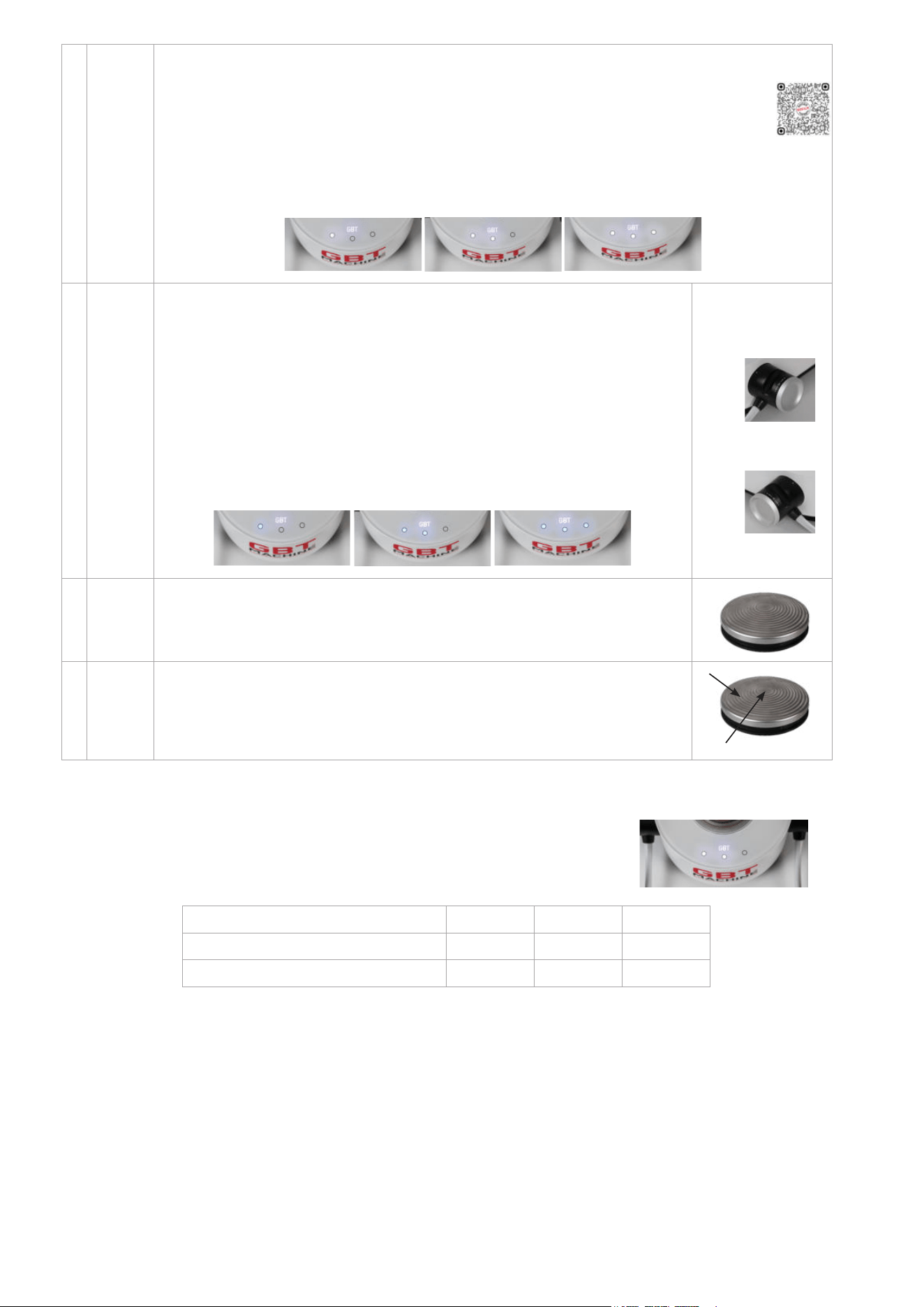
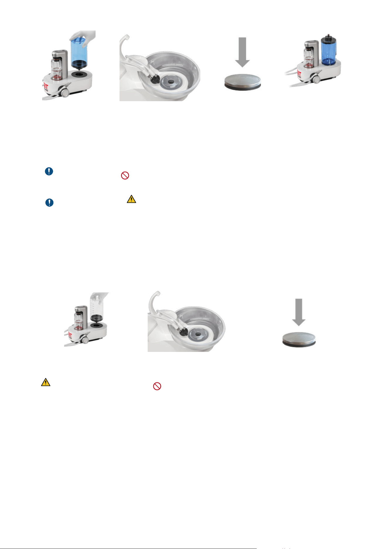
1 2 3 4
CLEANER
Place the CLEANER bottle fully
filled, switch ON
the device and lift both
handpieces from their holders.
The 3 blue LED lights are ON
and a sonar sound will start
playing.
Remove both handpieces
from their cord connectors.
Connect the CLIP+CLEAN on
the cord connectors and put
them over a sink.
Press the pedal,
then wait for 20 seconds.
Disconnect the CLEANER
bottle and release the pressure
by unscrewing the cap.
Before placing, remove
CLIP+CLEAN from the device.
Each cleaning consumes 30ml
of CLEANER.
Before cleaning, check
that the liquid level is above
the black flange of the bottle’s
neck.
Contamination prevention:
DO NOT make any contact
between the sink and the
handpiece cords.
CLIP+CLEAN shall be
reprocessed after each use.
The 3 buttons will blink to
indicate the progress.
Cleaning can be paused and
restarted by pressing the
pedal.
Then screw the cap back on
and place the bottle upside
down on the device to indicate
that the device needs to be
rinsed before the next use.
The CLEANER bottle
must be left upside down on the system overnight, to remind the user that the CLEANER has to be
completely flushed out of the system in the morning before treatment.
Every morning before the rst patient: Water lines rinse
1 2 3
H
2
O
Place the water bottle fully filled. Hold both handpiece cords with
CLIP+CLEAN over a sink.
Press the pedal, then
wait 20 seconds.
To reduce the risk of ingestion of the
cleaning agent by the patient, always use
a fully filled 800ml water bottle.
Contamination prevention:
DO NOT make any contact
between the sink and the
handpiece cords.
The 3 buttons will blink to indicate the progress.
Rinsing can be paused and restarted by pressing
the pedal.
Remove the water bottle and rinse well prior to
filling with water for the first patient of the day.
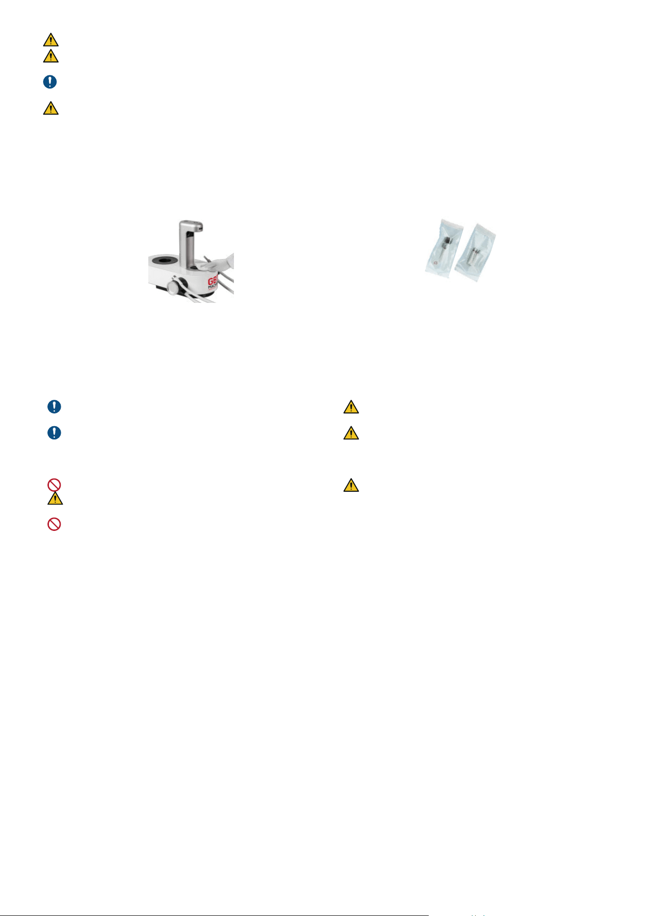
26
DO NOT leave water in your water bottles overnight. Allow the bottles to air with the lids off overnight.
Risk of ingestion of the cleaning agent. Check that no more residue of CLEANER is flushing out of the handpiece cord.
Otherwise, repeat the rinsing procedure.
Always empty out and wash the water bottle used for rinsing before any new use. EMS recommends a weekly use of a bottle
cleaning agent (e.g. BC-San 100 from Alpro Medical GMBH).
Risk of ingestion of residue of cleaning agent. During rinsing, a small quantity of cleaning agent flows back into the water
bottle.
4.2- Device cleaning and parts reprocessing
After every patient
Overall cleaning and disinfection
1 2
Use a cleaning and disinfecting wipe (less than 35% alcohol)
compatible EPA-registered intermediate level surface disinfectant
or that complies with the standards applicable in the country (e.g.
MICROKLEEN or Opti-Cide³ wipes).
Reprocess handpieces and instruments. Please refer
to FB-358/NA “reprocessing instructions”.
Wipe and dry the device after disinfection and/or
decontamination.
Once a week use a damp microfibre cloth with warm water to
remove the residue build up that all wipes can leave on your GBT
AIRFLOW
®
Prophylaxis Master, handpiece cords and handpieces
followed by a dry off with a soft non lint cloth.
DO NOT use paper towels as these can be abrasive.
Follow carefully the instructions provided by the wipes
manufacturer.
DO NOT use Advantaclear wipes. It damages EMS products
Risk of contamination. Always disinfect the bottom
and top areas of device air connections.
Please remember to dry your AIRFLOW
®
MAX and
PIEZON
®
handpiece cord connections and ensure they
are cooled and dried prior to each use. Excess moisture
can cause blockages.
Follow the recommendations of the "Reprocessing
Instructions" manual (FB-358/NA) regarding procedure
for cleaning and sterilizing the components, and the
present-day regulations on reprocessing in effect in
your country.
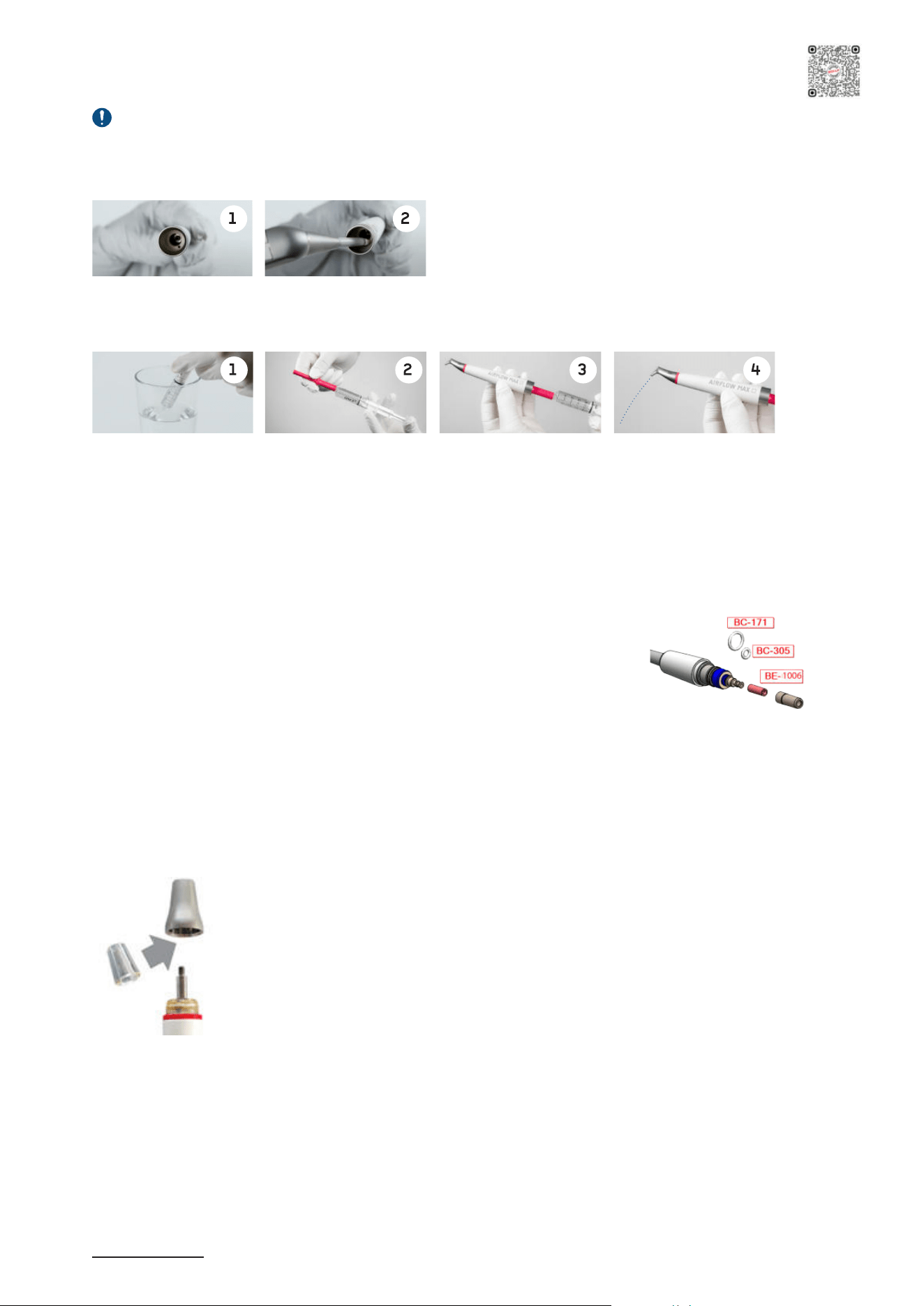
27
5- MAINTENANCE
5.1- AIRFLOW
®
MAX/PERIOFLOW
®
MAX handpiece daily maintenance
Before the reprocessing or in case of a clogged AIRFLOW
®
MAX and PERIOFLOW
®
MAX handpieces: use Easy Clean
provided in your AIRFLOW
®
Application box.
1- Clean the water channel:
AIR
Clear the water channel with air
2- Clean the air-powder channel with Easy Clean:
f Fill the syringe with distilled water
f Connect the Easy Clean
f Connect the handpiece
f Rinse the air-powder channel
The Easy Clean can be thermally sterilized at up to 135°C in the autoclave.
5.2- AIRFLOW
®
MAX/PERIOFLOW
®
MAX handpiece leakage
In case of leakage between handpiece and handpiece cord connector, replace the cord
gaskets with the spare parts provided in the EL-1211 kit located in the GBT Machine
AIRFLOW
®
Prophylaxis Master Maintenance Kit. Contact EMS aftersales service in
Southlake if needed.
5.3- PIEZON
®
handpiece leakage
In case of leakage between handpiece and handpiece cord connector please contact EMS aftersales service to replace the
BC-1039 PIEZON
®
connector o-ring.
5.4- Light guide check & replace
11
The light guide loses its transparence after undergoing repeated reprocessing cycles. Check the transparency of it every month
and proceed as follows:
1. Remove the PIEZON
®
Instrument and unscrew the handpiece nose cap by hand.
2. Take off the light guide and inspect it.
3. Place in a new light guide .
4. Screw the nose cap on again, by hand only.
11 Only valid for PIEZON
®
handpiece LED
Scan for support
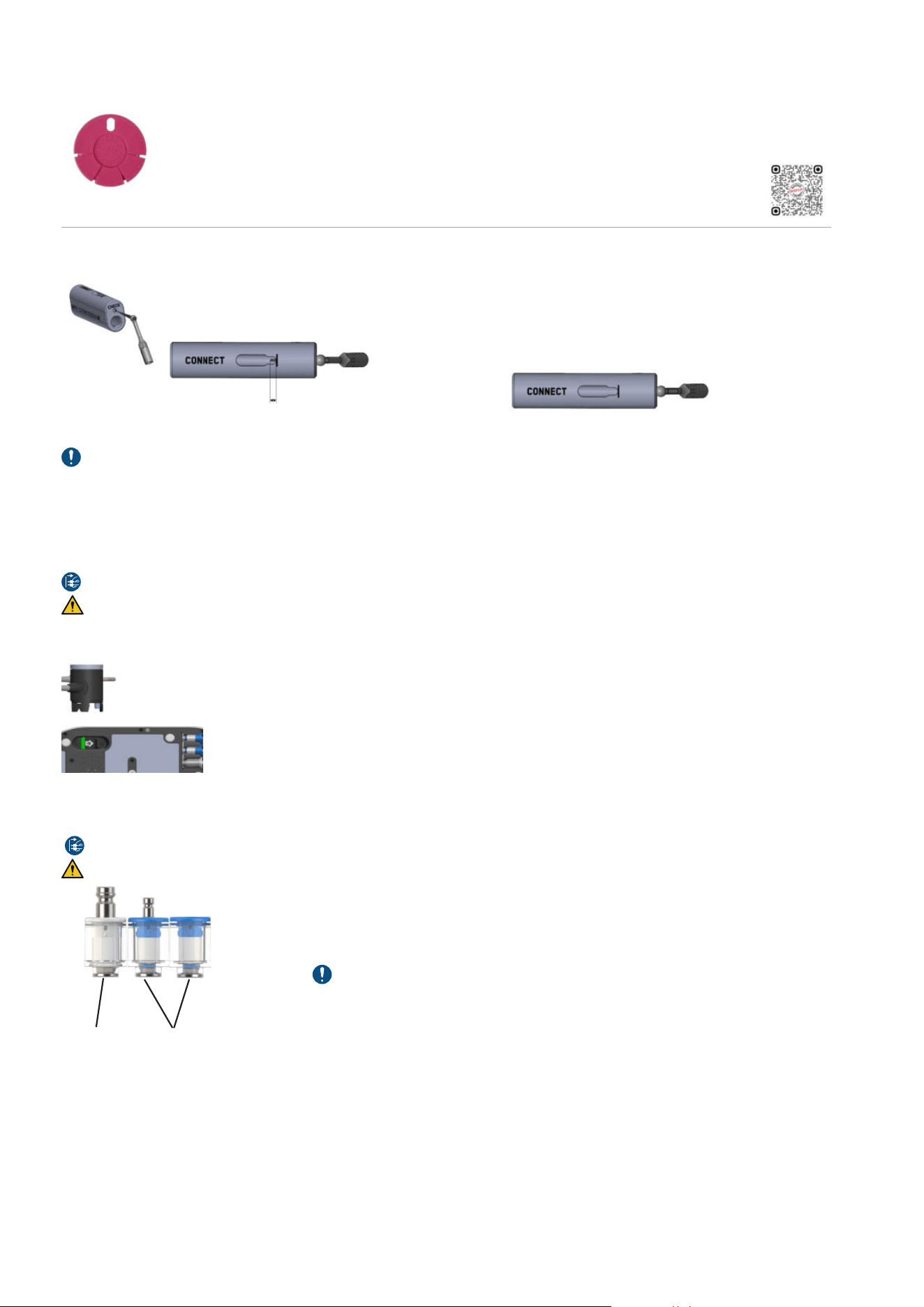
28
5.5- Wear
For PIEZON
®
instruments, check regularly instrument length and tip using the PIEZON
®
instrument check
tool. Ultrasound instruments wear during use and become shorter. Worn instruments are ineffective and are
a cause of discomfort to the patient. If PIEZON
®
instrument extremity reaches or is shorter than the limit
indicated by the GBT logo, it can have excessive and uncontrolled vibration. Replace the PIEZON
®
instrument.
Scan for support
For the PIEZON
®
PI MAX instrument, check the tip length with the PI TOOL or the PIEZON
®
instrument check
tool.
Remove the SCREW from the PI TOOL base.
Gently place the TIP in the hole marked CHECK up to STOP.
If the TIP sticks out, it can continue to be used.
If the TIP does not stick out = TIP too short. Replace
the PIEZON
®
PI MAX instrument
For precautionary reasons, do not exceed the validated lifespan of the components (see the "TECHNICAL DESCRIPTION"
section).
Always use EMS original products. Using non-original components may damage the equipment, and practitioner or patient may
be injured.
5.6- Handpiece cord system replacement
Disconnect the mains plug for purposes of maintenance and in case of malfunction.
Depressurize the powder chamber before disconnecting the AIRFLOW
®
MAX handpiece cord system.
In case of persistent malfunction or damage to the PIEZON
®
or AIRFLOW
®
MAX handpiece cord system, the part can be easily
replaced by the user. Follow the directions for replacement provided with the spare part supply.
Hanpiece cord system disconnecting procedure:
1. Unlock the hanpiece cord system by pushing the lock switch to the front
(Switch located under the device).
2. The handpiece cord system is now unlocked and can be removed by pulling it.
5.7- Monthly check
Each month check for cleanliness of both air and water filters.
Disconnect the mains plug for purposes of maintenance and in case of malfunction.
No maintenance is allowed while in use with a patient.
Check water and air
filters cleanliness
Filter color has to be white without significant visible
impurities. If not, replace the filter.
If the water filters needs to be changed more than
3 times a year, please check the quality of your tap
water.
Air filters usually remain cleaner for longer periods of
time. Replace once a year. (The yearly maintenance
service includes the replacement of the 3 filters.
air filter water filters
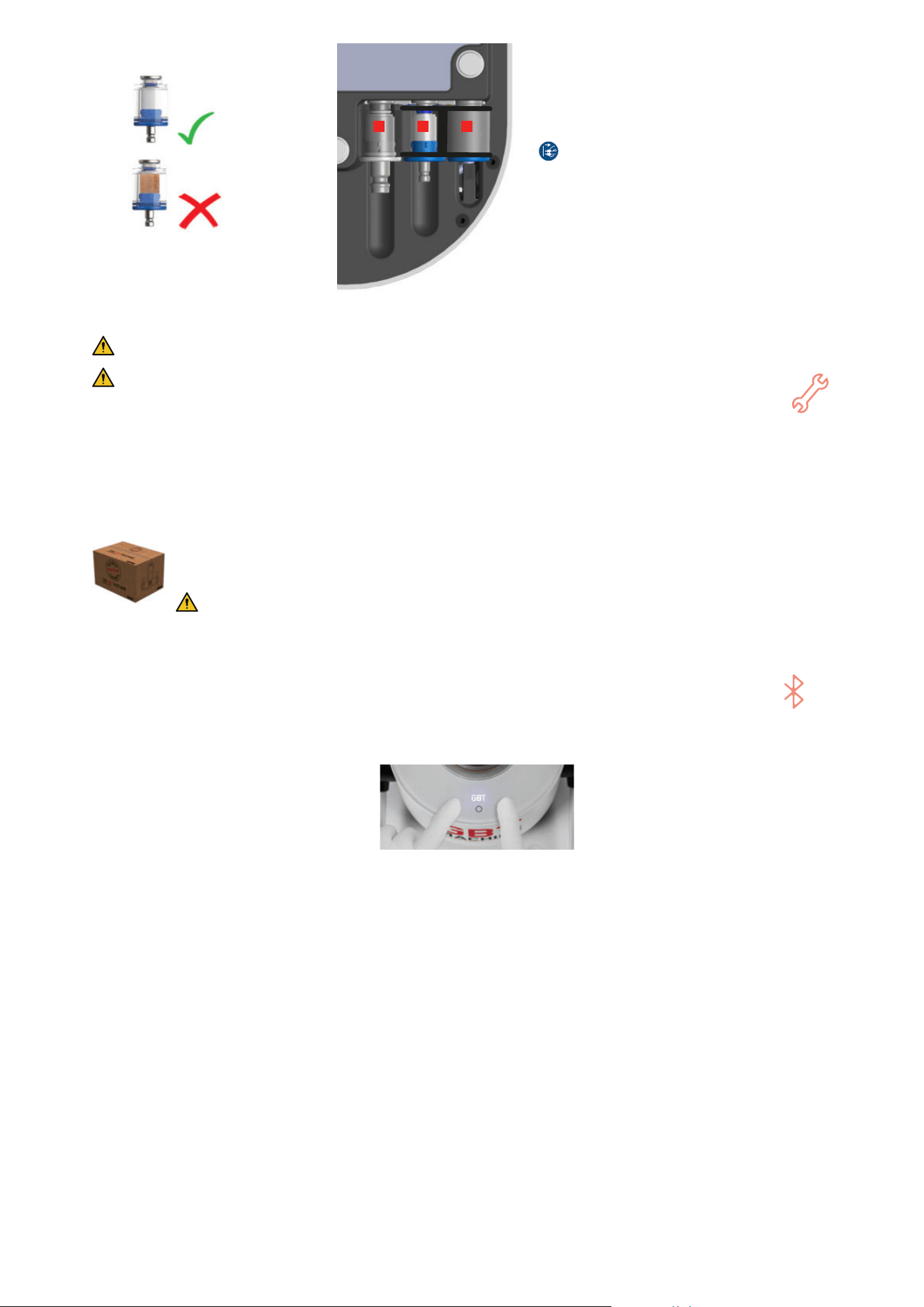
29
Good
Worn-out
1 2 3
To change the water and air filters from your device
on a GBT Station or other support, remove the device
from the support via the centre screw.
Then follow the procedure below:
1.
Disconnect the power cord from the grid first.
2. Disconnect the central water and air hoses by pulling
it off the connector.
3. Pull the filter off by hand or by using a small flat
screwdriver. To remove the water bottle filter (3), press
the clip (shown in the picture on the left) with your
finger.
4. Replace with a new filter and reconnect the hose.
5.8- Preventive maintenance and repair
EMS devices and products must only be maintained and/or repaired by EMS service center in Southlake.
A preventive maintenance each 2000 hours (this is when the wrench symbol on your device is ON prompting
you to contact your EMS service provider), is required as means of safety and performance guarantee for both
the patient and the user.
Qualified service repair may also be required anytime persistent malfunctioning is detected by the user and/or
reported by the device diagnostic.
The remote maintenance mode allows EMS aftersales service to use your device informations in order to resolve
certain failures more quickly and easily. If the failure cannot be resolved remotely by the 1st level support, you
will need to return your device.
When returning the device for service, it is recommended that you ship the device with its pedal, powder chamber,
bottles and handpiece cords in its original packaging for optimal protection against damage during transportation.
Provide the contact details of your EMS dealer for a quicker service process (see section 6.4).
Reprocess your device before returning it to EMS aftersales service in Southlake.
5.9- Pairing a (new) pedal
If bluetooth symbol is solid orange or if you want to pair a new pedal, follow the procedure below:
1. Place the two handpieces in their holders.
2. Press briefly left and right buttons simultaneously (3 secondes). A sonar sound will start playing (if not, repeat step 3).
3. Remove one battery from the pedal (no need to remove both). While the sonar sound plays, replace the battery into the
wireless pedal.
4. Within a short time (less than 15 seconds), the pairing will be complete, the 3 white LEDs will blink for a while, and the
bluetooth logo will switch to white and then disappear ; the device is then ready for use.
If the process takes longer than 1 minute, it means the pairing has failed and the device will automatically exit the mode. (No
more sonar sound and no blinking at exit).
In case of this process failure, turn the machine OFF, wait 10 seconds, then turn it ON again and redo the procedure from the
beginning.

30
6- TROUBLESHOOTING
For each troubleshooting procedure of the section "6- Troubleshooting", follow the steps one by one until your problem is
solved. Once you have tried all the steps and if the problem persists, please contact your local EMS aftersales service/dealer.
6.1- For AIRFLOW
®
/PERIOFLOW
®
products
No powder/air jet coming from the handpiece
1° Depressurize/repressurize the powder chamber
2° If applicable, change the PERIOFLOW
®
nozzle
3° Depressurize the powder chamber and unclog AIRFLOW
®
MAX/PERIOFLOW
®
MAX handpiece, as described in the section "5.1-
AIRFLOW
®
MAX/PERIOFLOW
®
MAX handpiece daily maintenance" and clean and dry the handpiece cord connector
No water spray is coming from the PERIOFLOW
®
nozzle
1° Check that water setting is on 3 and put power setting to 3
2° Change the PERIOFLOW
®
nozzle
3° Unclog PERIOFLOW
®
MAX handpiece, as described in the section "5.1- AIRFLOW
®
MAX/PERIOFLOW
®
MAX handpiece daily
maintenance" and clean and dry the handpiece cord connector
Water leakage between the handpiece and the PERIOFLOW
®
nozzle (unusual leak of droplets)
1° Check for powder residue between the PERIOFLOW
®
nozzle and the handpiece
2° Check the alignment/position of the PERIOFLOW
®
nozzle on the handpiece
3° Change the PERIOFLOW
®
nozzle
Water leakage between the AIRFLOW
®
MAX/PERIOFLOW
®
MAX handpiece and the handpiece cord.
1° Check that the handpiece is correctly connected to the handpiece cord
2° Unclog AIRFLOW
®
MAX/PERIOFLOW
®
MAX handpiece, as described in the section "5.1- AIRFLOW
®
MAX/PERIOFLOW
®
MAX handpiece
daily maintenance" and clean and dry the handpiece cord connector
3° Replace the AIRFLOW
®
cord gaskets as described in the section "5.2- AIRFLOW
®
MAX/PERIOFLOW
®
MAX handpiece leakage"
Insufficient or no water from AIRFLOW
®
MAX/PERIOFLOW
®
MAX handpiece
1° Check that your water setting is on 3
2° If applicable, change the PERIOFLOW
®
nozzle
3° Unclog AIRFLOW
®
MAX/PERIOFLOW
®
MAX handpiece, as described in the section "5.1- AIRFLOW
®
MAX/PERIOFLOW
®
MAX handpiece
daily maintenance" and clean and dry the handpiece cord connector
4° Check your water filter cleanliness and replace it if necessary, as described in the section "5.7- Monthly check"
Disconnect the mains plug before servicing any filter
5° Make sure you have correctly connected your water supply and with sufficient pressure
The unit efficiency decreases
1° Depressurize the powder chamber
2° Check the powder chamber level, as described in section 3, "Filling the powder chambers"
3° Check the air pressure of the dental unit
4° If applicable, change the PERIOFLOW
®
nozzle
5° Unclog AIRFLOW
®
MAX/PERIOFLOW
®
MAX handpiece, as described in the section "5.1- AIRFLOW
®
MAX/PERIOFLOW
®
MAX handpiece
daily maintenance" and clean and dry the handpiece cord connector
If the handpiece falls
AIRFLOW
®
MAX handpiece:
1° Check the state of the nozzle
2° Check if the handpiece is working
properly
3° Replace the handpiece by a new/
another handpiece
PERIOFLOW
®
MAX handpiece:
1° Check you can replace the PERIOFLOW
®
nozzle
2° Check the handpiece is still working properly
3° Replace the handpiece by a new/another handpiece
6.2- For PIEZON
®
products
The PIEZON
®
handpiece heats up
1° Check that power setting is on 2 and water setting is on 3
2° Take off the handpiece from the handpiece cord connector and wait 5 minutes for it to cool
White LED PIEZON
®
is not working
12
1° Clean and dry the PIEZON
®
handpiece and the handpiece cord connector
2° Put back the PIEZON
®
handpiece into the holder and wait 1 minute
Insufficient LED PIEZON
®
lighting
16
1° Replace the light guide
2° Replace the handpiece by a new/another handpiece
Water leakage between the PIEZON
®
handpiece and the handpiece cord
1° Check that the handpiece is correctly connected to the handpiece cord
2° Clean and dry the PIEZON
®
handpiece and the handpiece cord connector
3° Replace the PIEZON
®
connector o-ring as described in the section "5.3- PIEZON
®
handpiece leakage"
12 Only valid for PIEZON
®
handpiece LED
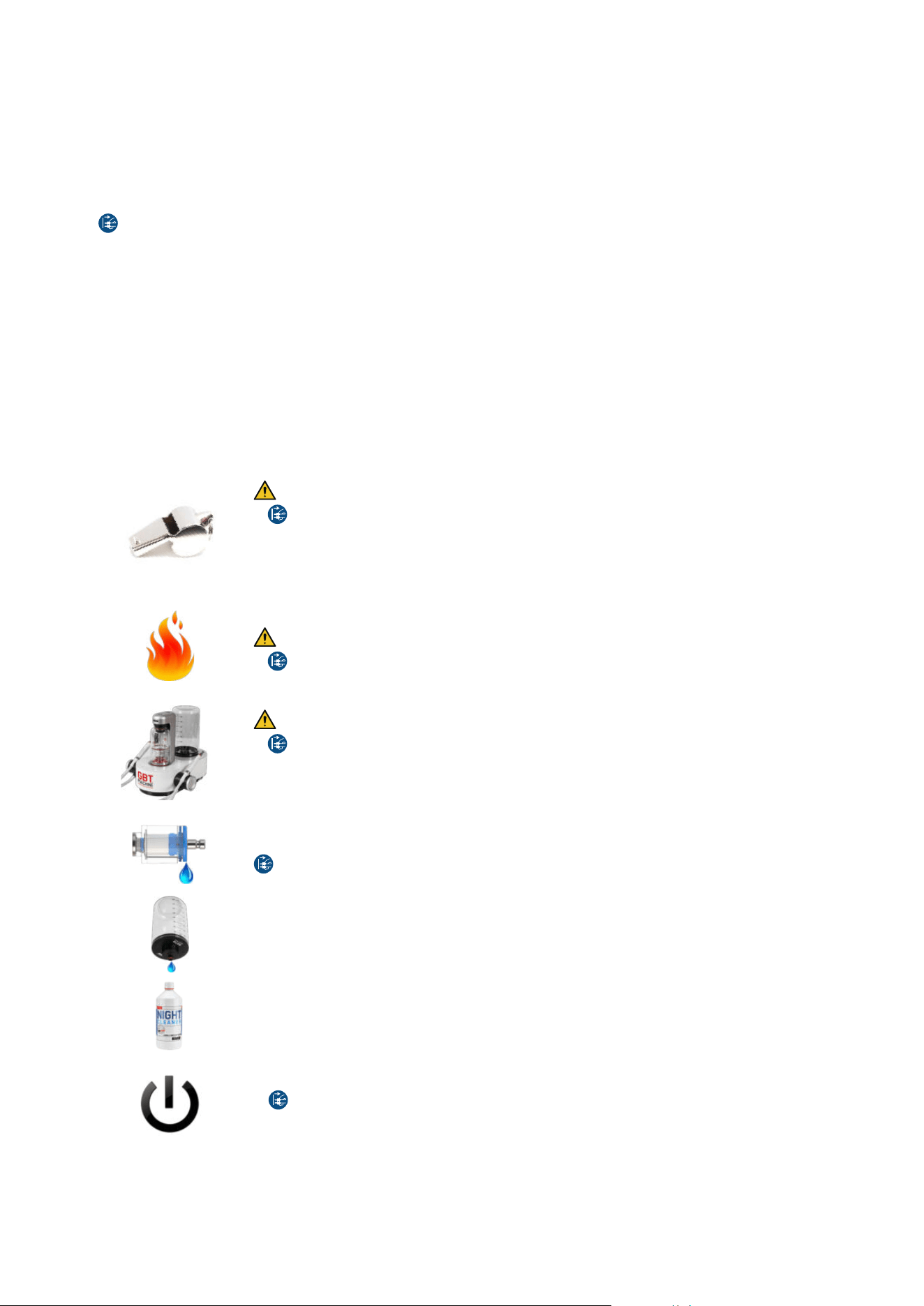
31
Low or no mechanical power delivered by PIEZON
®
or vibration perceived
1° Make sure that the PIEZON
®
instrument is correctly screwed on (use the CombiTorque
®
tool)
2° Check the wear of the PIEZON
®
instrument with the check tool (see section "5.5- Wear"), and replace it if necessary
3° Clean and dry the PIEZON
®
handpiece and the handpiece cord connector
No or low water flow
1° Check that your water setting is on 3
2° Blow compressed air through the PIEZON
®
instrument
3° Replace the PIEZON
®
instrument
4° Clean and dry the PIEZON
®
handpiece and the handpiece cord connector
5° Check your water filter cleanliness and replace it if necessary, as described in the section "5.7- Monthly check"
Disconnect the mains plug before servicing any filter
6° Make sure you have correctly connected your water supply and with sufficient pressure
Suspicious noise
1° Check the correct screwing with the CombiTorque
®
2° Check the wear of the PIEZON
®
instrument with the check tool (see section "5.5- Wear"), and replace it if necessary
If the handpiece falls
1° Check the state of the PIEZON
®
instrument, and replace it if necessary
2° Check if the handpiece is working properly
3° Replace the handpiece by a new/another handpiece
6.3- For the device
6.3.1- Device troubleshooting
The device is whistling or making strange noises
Risk of bottle explosion
1°
Disconnect the mains plug and stop using your device immediately
2° Check the water bottle for crack or any damage and, if the case, replace it with a new one
3° Check the supplied air pressure: it must be between 4.5 bar and 7 bar
4° If the device temperature is below 10°C (device too cold), wait for it to warm-up at ambient temperature
and then reconnect to the power grid and switch it on again
The device is making smoke (and fire)
Risk of fire and electric shock
1°
Disconnect the mains plug and stop using your device immediately
Handpiece cord or device leakage
Risk of fire and electric shock
1°
Disconnect the mains plug
2° If the leak come from the AIRFLOW
®
handpiece, go to "6.1- For AIRFLOW
®
/PERIOFLOW
®
products", if the
leak come from the PIEZON
®
handpiece, go to "6.2- For PIEZON
®
products"
3° If the leak come from AIRFLOW
®
MAX/PIEZON
®
handpiece cord system, disconnect it from the device and
clean the male and female connectors of the handpiece cord system
Water filter leakage
1° Check your water filter cleanliness and replace it, if necessary, as described in section "5.7- Monthly check"
Disconnect the mains plug before servicing any filter
Bottle/bottle connection leakage
1° Ensure the bottle cap has been correctly closed
2° Clean both connections: cap and device sides
3° Replace the bottle
Cleaning liquid remaining after water lines rinsing
1° Make sure your water setting is on 3
2° Make sure you have correctly connected your water supply and with sufficient pressure
3° Perform a second rinsing phase before treatment
The unit does not start
1° Check the power grid is correctly connected
2°
Disconnect the mains plug and remove the power cord from the device
3° With the help of a small flat screwdriver, open the fuse-holder cover
4° Replace fuses only with the exact type required, as described in section "TECHNICAL DESCRIPTION"
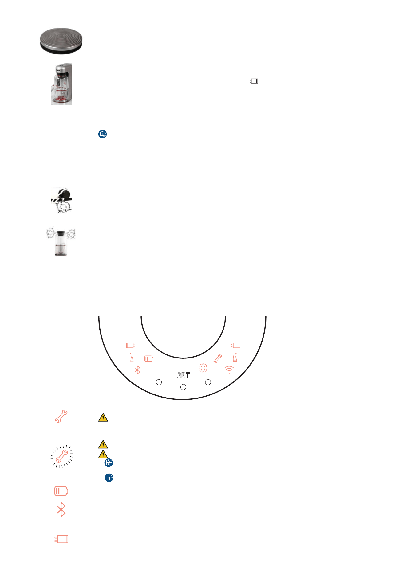
32
Wireless pedal does not work
1° Release the pedal and wait for 1 minute
2° Disconnect and reconnect both PIEZON
®
and AIRFLOW
®
MAX handpiece cord systems, as described in
the section "2.8- Check the handpiece cord system connections"
3° Pair the wireless pedal, as described in section "5.9- Pairing a (new) pedal"
4° Replace both batteries from the wireless pedal with new high-quality AA lithium batteries
No pressurization of the powder chamber
1° Check that your device is ON: GBT symbol is lighted (white, or pink for GBT certified practicians)
2° Check that AIRFLOW
®
MAX handpiece cord system symbol is OFF and that it is well connected, as
described in the section "2.8- Check the handpiece cord system connections"
Powder chamber white light is BLINKING during pressurization attempt
1° Make sure you have correctly connected your air supply and with sufficient pressure
2° Check your air filter cleanliness and replace it if necessary, as described in section "5.7- Monthly check"
Disconnect the mains plug before servicing any filter
Powder chamber white light is BLINKING at depressurization
1° Unclog AIRFLOW
®
MAX/PERIOFLOW
®
MAX handpiece, as described in the section "5.1- AIRFLOW
®
MAX/
PERIOFLOW
®
MAX handpiece daily maintenance" and clean and dry the handpiece cord connector
Powder sprays out of chamber at depressurization
1° Check the powder chamber level, as described in section 3 "Filling the powder chambers"
Powder leaks under the AIRFLOW
®
MAX handpiece cord system
1° Switch OFF the device and disconnect AIRFLOW
®
MAX handpiece cord system, as described in the section
"2.8- Check the handpiece cord system connections"
2° Clean and dry the male and female electrical contacts (mini-jack) of the AIRFLOW
®
MAX handpiece cord
system
3° Replace your AIRFLOW
®
MAX handpiece cord with a new one
Powder chamber is leaking
1° Clean and dry the powder chamber bottom and cap, including the o-ring, as well as the connection points
on the caliper
2° Replace the powder chamber
6.3.2- Symbols troubleshooting
REMINDER: For each troubleshooting procedure of the section "6- Troubleshooting", follow the steps one by one until your
problem is solved. Once you have tried all the steps and if the problem persists, please contact your local EMS aftersales
service/dealer.
Wrench symbol is ON
Maintenance indicator. It is time to send your device to yearly maintenance service.
Quickly contact EMS aftersales service in Southlake.
Wrench symbol is BLINKING
Permanent or transitory hardware fault condition detected
Risk of fire and electric shock
1°
First disconnect the mains plug and stop using your device immediately
2° Wait for 30 seconds, then plug it back again and restart the device
3°
Disconnect again the mains plug and wait for 1 hour, then plug it back again and restart the device
Battery symbol is ON
1° Replace both batteries from the wireless pedal with new high-quality AA lithium batteries
Bluetooth symbol is ON
1° Pair the wireless pedal, as described in section "5- Maintenance" --> "5.9- Pairing a (new) pedal"
AIRFLOW
®
MAX handpiece cord system symbol is ON
1° Switch OFF the device and disconnect AIRFLOW
®
MAX handpiece cord system, as described in the section
"2.8- Check the handpiece cord system connections"
2° Clean and dry the male and female electrical contacts (mini-jack) of the AIRFLOW
®
MAX handpiece cord
system
33
PIEZON
®
handpiece cord system symbol is ON
1° Switch OFF the device and disconnect PIEZON
®
handpiece cord system, as described in the section "2.8-
Check the handpiece cord system connections"
2° Clean and dry the male and female electrical contacts (mini-jack) of the PIEZON
®
handpiece cord system
AIRFLOW
®
MAX/PERIOFLOW
®
MAX handpiece symbol is ON
1° Check that AIRFLOW
®
MAX/PERIOFLOW
®
MAX handpiece contains the RFID/NFC logo.
2° If it is the case, check that this handpiece is correctly connected to the handpiece cord connector.
3° If the logo RFID/NFC is missing, you can use your EMS handpiece but you will be restricted in connectivity.
Contact your EMS representative for further assistance and information.
PIEZON
®
handpiece symbol is ON
1° Check that PIEZON
®
handpiece contains the RFID/NFC logo.
2° If it is the case, check that this handpiece is correctly connected to the handpiece cord connector.
3° If the logo RFID/NFC is missing, you can use your EMS handpiece but you will be restricted in connectivity.
Contact your EMS representative for further assistance and information.
Wifi symbol is ON
(when switching ON the device)
1° To connect your GBT Machine AIRFLOW
®
Prophylaxis Master to the wifi, press simultaneously the buttons
2 and 3, as described in the section "2.5.1- Connecting / Disconnecting from the Wi-Fi"
2° Open your EMS interface to select the right network and enter the password
Please refer to the the section "2.5.1- Connecting / Disconnecting from the Wi-Fi" for more information.
NB: If you want to skip this step, touch the ON/OFF button on the caliper
Upgrade software symbol is ON
(when switching ON the device)
To launch the software upgrade, press simultaneously the buttons 2 and 3 during 2 seconds.
The maintenance key symbol will light up and fade several times. This step may take between 10 seconds and
3 minutes, depending on the update performed.
NB: If you want to skip this step, touch the ON/OFF button on the caliper. The next time you turn ON your
device, this update will be requested again.
6.4- Contact EMS aftersales service
ELECTRO MEDICAL SYSTEMS L.L.C.
2150E Continental Boulevard
Southlake, Texas, 76092, US
T. +1 972 690 8382
E-mail: custsvc@ems-na.com
Aftersales: emsrepairs@ems-na.com
6.5- Report an adverse event
If any serious incident occurs that is directly or indirectly related to the treatment, report it immediately to EMS and to the
competent authority of your country and of where the patient is established (if different).
Adverse Event notification to EMS
By email: vigilancemailbox@ems-ch.com
By fax: +41 (0) 22 99 44 701
By post: E.M.S. Electro Medical Systems S.A., Chemin de la Vuarpillière 31, 1260 Nyon – Switzerland
Scan for support
34
SUSTAINABILITY
1- DISPOSAL OF WASTE
The device must not be discarded in domestic household waste. Should you wish to definitively
dispose of the device, please comply with the regulations that apply in your country.
Other parts of this device, including tips/inserts, and chemicals must be disposed of according to
your country’s regulations.
Keep the original packaging until the device is to be disposed of permanently. It can be used for
shipping or storing.
2- SUSTAINABLE DESIGN
The device, on a voluntary basis, respects the latest Eco design low energy standby and off mode
consumption regulation
13
. Packaging cardboards are recycled and recyclable.
Printed instructions are aligned with a sustainable development policy and are certified "Myclimate
neutral imprimerie" and "FSC".
WARRANTY
The warranty is valid if you complete maintenance 2000 hours after purchase and then 2000 hours after each last maintenance.
Warranty is void if the device has been used with non-original EMS powder, instruments and handpieces. Warranty is void if the
device has been opened.
EMS and the distributor of this device accept no liability for direct or consequential injury or damage resulting from improper
use, arising in particular through non-observance of the instructions for use, or improper preparation and maintenance.
EMS declines the responsibility for the safety of the device and declares the warranty null and void if service or repair is carried
out by an unauthorized third party or if non-genuine spare parts are used.
TECHNICAL DATA COLLECTION AND PRIVACY POLICY
During maintenance and/or repair of the device, EMS or any authorized EMS repair center will have access to certain technical
information such as usage statistics (hereinafter “Technical Data”), collected during the device service.
Such technical data shall be analyzed and used by EMS in its legitimate interest, e.g. to carry out statistical analysis and to
improve its customer service and/or its Research and Development processes.
EMS may also use such technical data along with your personal details in order to be able to understand your personal usage
of the device and offer you a better customer experience and tailored service. However, you can unsubscribe from this process
at any time, by simply sending us an email at privacy@ems-ch.com.
Rest assured that these activities will be carried out in compliance with applicable data protection laws. For any questions
regarding your personal data, please consult our privacy policy at www.ems-company.com or send an email to privacy@
ems-ch.com.
13 European Commission Regulation N°1275/2008 of 17 December 2008 regarding the Eco design requirements for standby and off mode electric power
consumption of electronic household and ofce equipment.

35
TECHNICAL DESCRIPTION
Manufacturer E.M.S. Electro Medical Systems S.A.,
Chemin de la Vuarpillière 31,
1260 Nyon, Switzerland
Model GBT Machine AIRFLOW
®
Prophylaxis Master, product code FT-300
Classification IEC
60601-1
Electrical Insulation Class-I
Applied part Type B
IP21 Control unit
IP21 Foot pedal
Essential Performance This medical device has no Essential Performance in the meaning of the IEC 60601-1 :2020 - The device has
no function whose absence or degradation would result in an unacceptable risk.
Operating mode Continuous operation
Power supply 100-240Vac, 50-60Hz, 4A max.
Power consumption OFF-mode / Stand-by: 0.5W max.
Max: 700VA
Ultrasonic module Output Power: 8W under fully-loaded mechanical condition.
Frequency: 24-32kHz.
Primary tip vibration excursion: 200um max.
Fuse 5A, T (slow), 250Vac, H type (=T5H250V)
Filters Water filter: 50 micrometers
Air filter: 14 micrometers
Wireless communication
module
Radio Interface n°1 Radio Interface n°2 Radio Interface n°3 Radio Interface n°4
Type of Radio: WIFI
LTE
14
RFID Bluetooth Low Energy
Reference of Radio chipset-
module:
ESP32-S3-WROOM-1 ME310G1-WW STR25R3911B-AQTF BGM220SC22WGA2R
Frequency Bands: 2412 to 2484 MHz B1, B3, B8, B20, B28 13.56 MHz 2402 MHz to 2480 MHz
Voltage Range: 3.0 to 3.6 V 3.2 to 4.2 V 2.4 to 5.5 V 1.8 to 3.8 V
Temperature Range: -40 to + 85°C -40 to + 85°C -40 to + 125°C -40 to + 85°C
Antenna: PCB Gain 3.26 dBi Embedded Gain 5 dBi 0 dBi
Integral antenna Gain
2.3 dBi
Maximum Output Power: < 20 dBm
< 23 dBm < 42 dBµA/m
< 10 dBm
Weight Control Unit 5kg max. (full operating condition)
Foot pedal: 0.35kg max. (wireless pedal)
Dimensions Control Unit: Height: 245 mm, Width: 260 mm, Length: 290 mm
Wireless pedal: Diameter 135 mm, Height 35 mm
Operating conditions Temperature: 10°C to 35°C
Humidity: 30% to 75%
Altitude: Max 3000m
Pressure: 700hPa to 1060hPa
Under certain operating conditions, applied parts may exceed 41°C of temperature and reach a maximum
temperature of 48 °C.
Storage conditions Device only (with no water inside):
Temperature: 5°C to 40°C
Humidity: up to 85%
Pressure: 500hPa to 1060hPa
Accessories: see individual packaging
Device with accessories, in packaging:
Temperature: 5°C to 25°C
Humidity: up to 85%
Pressure: 500hPa to 1060hPa
Transport conditions Device only (with no water inside):
Temperature: -29°C to 38°C
Humidity: up to 85%
Pressure: 500hPa to 1060hPa
Accessories: see individual packaging
Device with accessories, in packaging:
Temperature: -20°C to 38°C
Humidity: up to 85%
Pressure: 500hPa to 1060hPa
14 Only for FT-300/A conguration
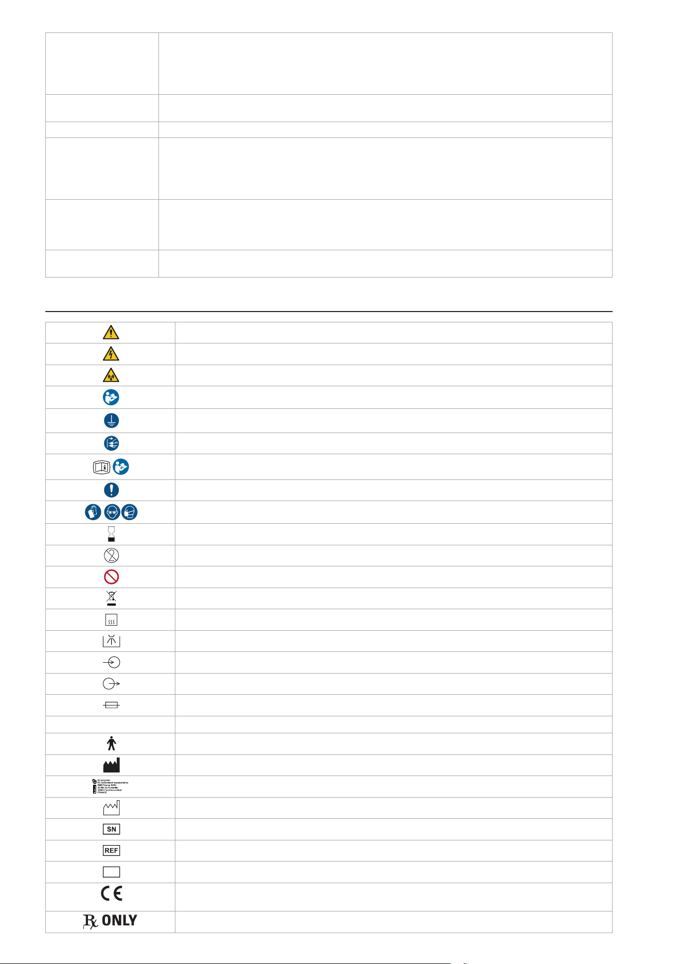
36
Input fluids Water: pressure 2-5bar, temperature 10-30°C, salinity 0.2% max., hardness from 8 to 12°dH, minimum flow-
rate 100ml/min, RECTUS 20KA connector type. EN-1717 compliant water network/inlet is required.
Note: The pH and particle size information are not relevant.
Air: pressure 4.5-7bar, dry-only (humidity 1.032g/m3 max.), oil filtered 0.1mg/m3 max., minimum flow-rate 20
Nl/min at 4.5bar, RECTUS 21KA connector type
Output fluids Water: min. 40ml/min. for AIRFLOW
®
, min. 30ml/min. for PIEZON
®
Air: max pressure 5bar for AIRFLOW
®
Shelf life PIEZON
®
and CLEANER bottles: 5 years
Validated lifetime Handpieces (main bodies): 1000 sterilization cycles
PI MAX instrument Tip: 20 sterilization cycles
PI MAX instrument Holder: 1000 sterilization cycles
Instrument PI: 100 sterilization cycles
Others intruments and their CombiTorque
®
: 1000 sterilization cycles
Lifespan PIEZON
®
instruments: Check PIEZON
®
instrument length and tip thread using the PIEZON
®
instrument check
tool.
PIEZON
®
PI MAX instrument: Use the PI MAX instrument Tool or the PIEZON
®
instrument check tool. The tip
mustn’t be shorter than 3mm.
Expected service life Device: 7 years, having regular recommended maintenance (every 2000 hours)
Handpiece cord systems : 2 years
SYMBOLS
General Warning
Warning Electricity
Non-ionizing radiation (radio communication)
Read the operation instructions
Device requiring protective earth
Disconnect the mains plug for purposes of maintenance and in case of malfunction
Electronic instructions for use
Mandatory action
Wear personal protective equipment
Expiration date
Single use. Do not re-use.
Do not do.
Disposal of old electronic equipment (European Union & other countries with separate collection systems)
135°C
Sterilizable at up to 135°C in the autoclave
Thermal disinfection
Input
Output
Fuse
IP ...
Protection against water permeability
Applied part, type B
Manufacturer
EU Authorized Representative
Manufacturing date
Serial number
Catalog number / Product reference
MD
Medical device
0124
Medical Device compliant with EU Regulation 2017/745
Number of the Notified Body
CAUTION: Federal (US) law restricts this device to sale by or on the order of a physician

37
ELECTROMAGNETIC COMPATIBILITY
This device has been designed and tested for compliance with IEC 60601-1 and IEC 60601-4-2 requirements for electromagnetic
immunity and emissions. Proper installation and use according to these instructions are essential to maintain Basic Safety.
1- INTENDED ELECTROMAGNETIC ENVIRONMENT
The GBT Machine AIRFLOW
®
Prophylaxis Master is intended for use in dental offices with typical mains power quality and
controlled electromagnetic conditions.
Use of this equipment adjacent to or stacked with other equipment should be avoided because it could result in improper
operation. If such use is necessary, this equipment and the other equipment should be observed to verify that they are operating
normally.
The use of parts other than those supplied or listed as accessory may negatively affect EMC performance.
The customer or the user of this product should assure that it is used in such an environment.
2- DEVICE PERFORMANCE AND EMC DISTURBANCE EFFECTS
This device has no Essential Performance as defined by IEC 60601-1:2020. Basic Safety is maintained even if electromagnetic
disturbances occur. However, EMC interference may temporarily affect normal operation.
If electromagnetic interference occurs, the operator may observe:
• Interruption or irregularity in powder spray or water flow
• Reduced ultrasonic power or unexpected variation in scaling performance
• Display malfunctions or unexpected shutdown
• Delayed response to pedal activation
3- CLINICAL IMPACTS
These effects may lead to treatment interruption or delay but do not create an unacceptable risk to patient safety.
4- OPERATOR ACTIONS
• Stop treatment immediately.
• Verify cabling and connections.
• Move portable RF communications equipment (e.g., mobile phones, Wi-Fi routers) at least 30 cm (12 inches) away from
the device.
• If interference persists, disconnect the device and contact EMS technical support.
5- COMPLIANCE LEVELS
The device was tested according to IEC 60601-4-2 and related standards. Immunity and emissions compliance levels are
summarized below:
Immunity test IEC 60601 test level Compliance level Electromagnetic environment - guidance
Electrostatic discharge (ESD)
IEC 61000-4-2
± 8 kV contact
± 15 kV air
Floors should be wood, concrete or
ceramic tile. If floors are covered with
synthetic material, relative humidity should
be > 30%.
Electrical fast transient/burst
IEC 61000-4-4
± 2 kV for power supply lines 100 kHz repetition
frequency
± 1 kV for input/output lines 100 kHz repetition frequency
Mains power quality should be that
of a typical commercial or hospital
environment.
Surge
IEC 61000-4-5
± 1 kV line(s) to line(s)
± 2 kV line(s) to earth
Mains power quality should be that
of a typical commercial or hospital
environment.
Voltage dips
IEC 61000-4-11
70 % UT (30 % dip in UT) for 25/30 cycles
0 % UT for 0,5 cycle at 0°, 45°, 90°, 135°, 180°, 225°, 270°
and 315°
0 % UT for 1 cycle single phase
Mains power quality should be that
of a typical commercial or hospital
environment. If the user of the product
requires continued operation during power
mains interruptions, it is recommended
that the product be powered from an
uninterruptible power supply or a battery.
Voltage interruptions
IEC 61000-4-11
0% UT for 5 s
0% UT for 250/300 cycles
Power frequency (50/60 Hz)
magnetic field
IEC 61000-4-8
30 A/m 30 A/m (50 Hz or 60 Hz) Power frequency magnetic fields should
be at levels characteristic of a typical
location in a typical commercial or hospital
environment.
38
Conducted RF
IEC 61000-4-6
3 V
150 kHz to 80 MHz
6V in ISM bands 150kHz
and 80 MHz
80 % AM at 1 kHz
3 V
150 kHz to 80 MHz
6V in ISM bands 150kHz
and 80 MHz
80 % AM at 1 kHz
Portable RF communications equipment
(including peripherals such as antenna
cables and external antennas) should be
used no closer than 30 cm (12 inches) to
any part of the GBT Machine AIRFLOW
®
Prophylaxis Master, including its cables.
Otherwise, degradation of the performance
of this equipment could result.Field
strengths from fixed RF transmitters,
as determined by an electromagnetic
site survey
15
, should be less than the
compliance level in each frequency range
16
.
Interference may occur in the vicinity of
equipment marked with the following
symbol:
or
Radiated RF
IEC 61000-4-3
3 V/m
80 MHz to 6 GHz
80% AM at 1 kHz
3 V/m
80 MHz to 6 GHz
80% AM at 1 kHz
Proximity fields from RF
wireless communications
equipment
IEC 61000-4-3
See Table below
IEC 61000-4-39 134.2 kHz / Modulation
pulsée 2.1 kHz / 65A/m
13.56 MHz / Modulation
pulsée 50 kHz / 7.5A/m
134.2 kHz / Modulation
pulsée 2.1 kHz / 65A/m
13.56 MHz / Modulation
pulsée 50 kHz / 7.5A/m
Notes:
- UT is the a. c. mains voltage prior to application of the test level.
- At 80 MHz and 800 MHz, the higher frequency range applies.
- These guidelines may not apply in all situations. Electromagnetic propagation is affected by absorption and reflection from
structures, objects and people.
6- PROXIMITY FIELDS FROM RF WIRELESS COMMUNICATIONS EQUIPMENT
IEC 61000-4-3
Test
Frequency
(MHz)
Modulation
Required level
(V/m)
Immunity test
level
(V/m)
385 Pulse Modulation 18Hz 27 27
450 Pulse Modulation 18Hz 28 28
710
745
780
Pulse Modulation 217 Hz 9 9
810
870
930
Pulse Modulation 18 Hz 28 28
1720
1845
1970
Pulse Modulation 217 Hz
28 28
2450 Pulse Modulation 217 Hz 28 28
5240
5500
5785
Pulse Modulation 217 Hz 9 9
NOTE: This equipment has been tested and found to comply with the limits for a Class B digital device, pursuant to part 15 of the FCC
Rules. These limits are designed to provide reasonable protection against harmful interference in a residential installation. This equipment
generates, uses and can radiate radio frequency energy and, if not installed and used in accordance with the instruction, may cause harmful
interference to radio communications. However, there is no guarantee that interference will not occur in a particular installation. If this
equipment does cause harmful interference to radio or television reception which can be determined by turning the equipment off and on,
the user is encouraged to try to correct interference by one or more of the following measures:
- Reorient or relocate the receiving antenna.
- Increase the separation between the equipment and receiver.
- Connect the equipment into an outlet on a circuit different from that to which the receiver is connected.
- Consult the dealer or an experienced radio/TV technician for help.
7- ELECTROMAGNETIC EMISSIONS COMPLIANCE
Emissions test Compliance Electromagnetic environment - guidance
RF emissions CISPR 11 Group 1 The product uses RF energy only for its internal function. Therefore, its
RF emissions are very low and are not likely to cause any interference in
nearby electronic equipment.
15 Field strengths from xed transmitters, such as base stations for radio (cellular/cordless) telephones and land mobile radios, amateur radio, AM and FM
radio broadcast and TV broadcast cannot be predicted theoretically with accuracy. To assess the electromagnetic environment due to xed RF transmitters, an
electromagnetic site survey should be considered. If the measured eld strength in the location in which the product is used exceeds the applicable RF compliance
level above, the product should be observed to verify normal operation. If abnormal performance is observed, additional measures may be necessary, such as re-
orienting or relocating the product.
16 Over the frequency range 150 kHz to 80 MHz, eld strengths should be less than 3 V/m.

39
RF emissions CISPR 11 Class B
The product is suitable for use in all establishments, including domestic
establishments and those directly connected to the public low-voltage
power supply network that supplies buildings used for domestic purposes.
Harmonic emissions IEC 61000-3-2 Class A
Voltage fluctuations / flicker emissions
IEC 61000-3-3
Complies
RADIO EQUIPMENT COMPLIANCY
This Medical Device and all of its accessories having radio equipment are compliant with the European Directive 2014/53/EU
(RED – Radio Equipment Directive) ), but not limited to the following standards and/or normative documents:
• EMC
• ETSI EN 301 489-1 V2.2.3
• ETSI EN 301 489-17 v3.2.4
• ETSI EN 301 489-3 v2.3.2
• ETSI EN 301 489-52 v1.2.1
• ETSI EN 300 330 v2.1.1
• EN 301 908-1 v15.1.1
• EN 301 908-13 v13.2.1
• SPECTRUM
• ETSI EN 300 328 v2.2.2
1- FCC STATEMENTS
Any changes or modifications not expressly approved by Electro Medical Systems for compliance could void the user's
authority to operate this equipment.
NOTE: This equipment has been tested and found to comply with the limits for a Class B digital device, pursuant to part 15 of the
FCC Rules. These limits are designed to provide reasonable protection against harmful interference in a residential installation.
This equipment generates, uses and can radiate radio frequency energy and, if not installed and used in accordance with the
instruction, may cause harmful interference to radio communications. However, there is no guarantee that interference will not
occur in a particular installation. If this equipment does cause harmful interference to radio or television reception which can
be determined by turning the equipment off and on, the user is encouraged to try to correct interference by one or more of the
following measures:
• Reorient or relocate the receiving antenna.
• Increase the separation between the equipment and receiver.
• Connect the equipment into an outlet on circuit different from that to which the receiver is connected.
• Consult the dealer or an experienced radio/TV technician for help
1.1- RF Exposure mobile Device
This device complies with FCC and IC radiation exposure limits set forth for general population. This device must be installed
to provide a separation distance of at least 20cm from all persons and must not be co-located or operating in conjunction with
any other antenna or transmitter.
This device complies with Part 15 of the FCC Rules. Operation is subject to the following two conditions: (1) this device may not
cause harmful interference, and (2) this device must accept any interference received, including interference that may cause
undesired operation.
1.2- RF Exposure portable device only for RFID
This device complies with FCC radiation exposure limits set forth for general population. This device must not be co-located or
operating in conjunction with any other antenna or transmitter.
2- ISED STATEMENTS
This device contains licence-exempt transmitter(s)/receiver(s) that comply with Innovation, Science and Economic Development
Canada’s licence-exempt RSS(s). Operation is subject to the following two conditions: (1) this device may not cause interference,
and (2) This device must accept any interference, including interference that may cause undesired operation of the device.
2.1- RF Exposure mobile Device
This device complies with ISED radiation exposure limits set forth for general population. This device must be installed to
provide a separation distance of at least 20cm from all persons and must not be co-located or operating in conjunction with
any other antenna or transmitter.

40
2.2- RF Exposure portable device only for RFID
This device complies with ISED radiation exposure limits set forth for general population. This device must not be co-located
or operating in conjunction with any other antenna or transmitter.
3 - WIRELESS COMMUNICATION MODULE, ONLY FOR COSTA RICA
Radio Interface n°1 Radio Interface n°2 Radio Interface n°4
Type of Radio: WIFI RFID Bluetooth Low Energy
Reference of Radio chipset-module: ESP32-S3-WROOM-1 STR25R3911B-AQTF BGM220SC22WGA2R
Frequency Bands: 2412 to 2484 MHz 13.56 MHz 2402 MHz to 2480 MHz
Voltage Range: 3.0 to 3.6 V 2.4 to 5.5 V 1.8 to 3.8 V
Temperature Range: -40 to + 85°C -40 to + 125°C -40 to + 85°C
Antenna: PCB Gain 3.26 dBi 0 dBi Integral antenna Gain 2.3 dBi
Maximum Output Power: 17.17 dBm -4.43 dBµA/m 9.97 dBm
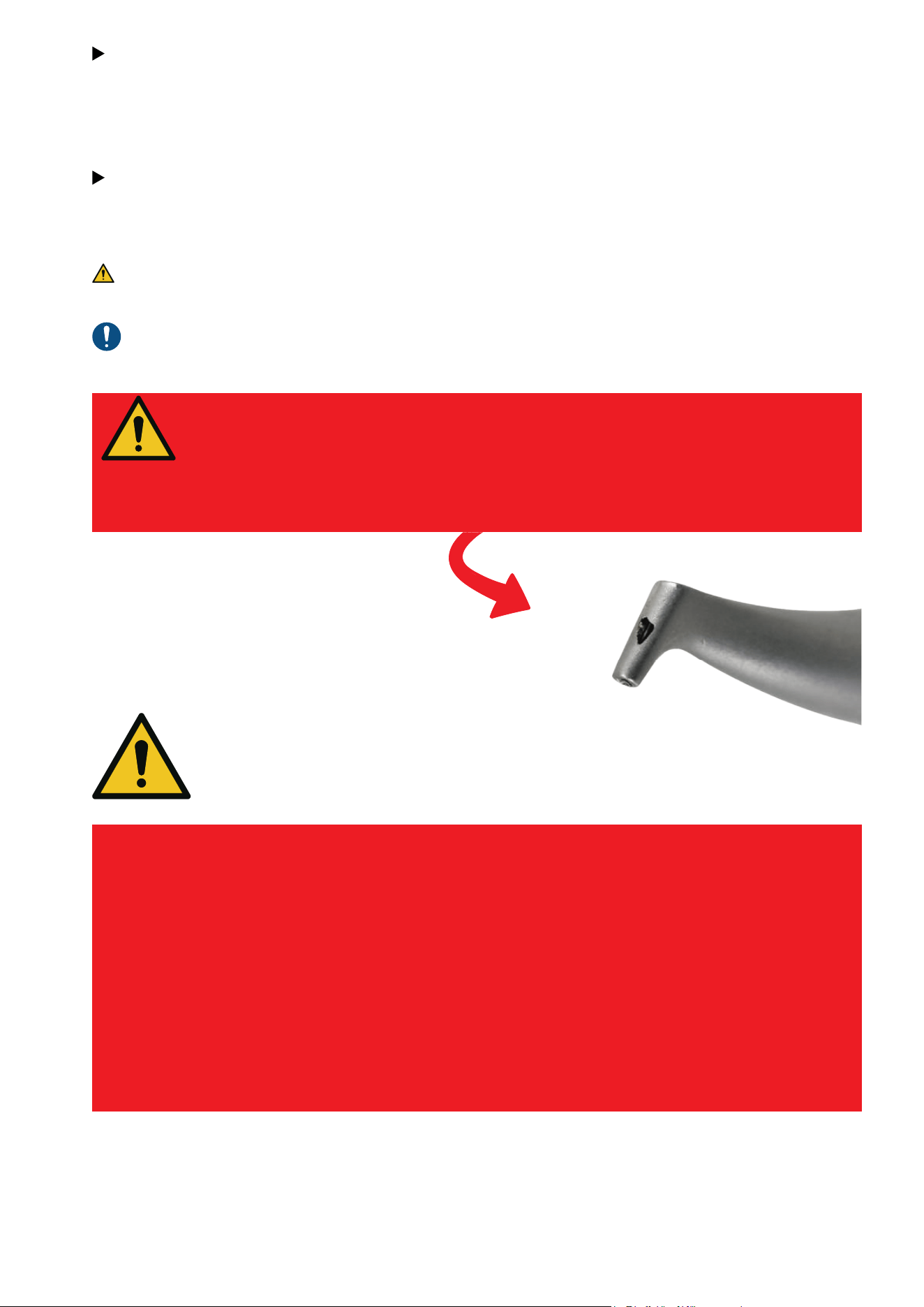
41
EMS powders are much less abrasive than traditional mechanical debridement techniques
such as rubber cups and handscaling.
We recommend to use AIRFLOW
®
and PERIOFLOW
®
first, followed by PIEZON
®
. GBT: the mini-
mally invasive way for Professional Mechanical Plaque Removal (PMPR).
As part of the GBT disclosing phase, coloration also minimizes AIRFLOW
®
abrasion. No more
color signifies that all biofilm has been removed: the objective of AIRFLOW
®
is achieved, to
preserve the integrity of dental tissues.
EMS devices have been designed and tested for exclusive use with EMS prophylaxis powders.
ONLY USE EMS POWDERS
So-called "EMS compatible" powders in the marketplace may cause
damage to oral tissues and the device.
See below a damaged AIRFLOW
®
nozzle after use with a
"compatible" powder. If EMS products are damaged by using
"compatible" powders the product Warranty will be lost.
ONLY USE THE SWISS ORIGINAL
EMS INSTRUMENTS!
The EMS Instrument, the Handpiece and the electronic module have to vibrate in
harmony like in a trilogy.
Using so-called “compatible” and copy tips from third parties can damage your
patients’ teeth as well as EMS handpieces.
They were developed and made for each other by EMS.
One PS Instrument is designed for up to 1000 treatments, thus reducing the cost
of one treatment to only a few cents.
Therefore, there is absolutely no reason to "save" money by using so-called
"compatible" tips. Moreover, if the Piezon Handpiece gets damaged (the thread)
it will lose its warranty so at the end of the day, “compatible” tips will always cost
you more.
Damaged
handpiece

42
NYON, SWITZERLAND
E.M.S. ELECTRO MEDICAL SYSTEMS S.A.
Chemin de la Vuarpillière 31
1260 Nyon
www.ems-dental.com/en/contact
www.ems-dental.com
T. +41 22 994 47 00
E-mail: w[email protected]m
HEADQUARTERS
WORLDWIDE EMS AFFILIATES
MADRID, SPAIN
EMS ELECTRO MEDICAL SYSTEMS S.L.
ESPAÑA SLU
C/ Tomás Bretón, 50-52 2ª planta
ES - 28045 Madrid
T. +34 91 528 99 89
E-mail: info@ems-espana.com
ES
LISBON,
PORTUGAL
EMSPOR - ELECTRO MEDICAL SYSTEMS
PORTUGAL, UNIPESSOAL LDA
Avenida Miguel Bombarda, 36, 6A
PT - 1050-165 Lisboa
T. +351 912 338 777
E-mail: i[email protected]m
PT
FONCINE,
FRANCE
EMS FRANCE SARL
32, route de Pontarlier
FR - 39460 Foncine-le-Haut
T. +33 3 84 51 90 01
F. +33 3 84 51 94 00
E-mail: info@ems-france.fr
FR
SOUTHLAKE, TEXAS,
UNITED STATES
OF AMERICA
ELECTRO MEDICAL SYSTEMS L.L.C.
2150E Continental Boulevard
Southlake, Texas, 76092, US
T. +1 972 690 8382
E-mail: custsvc@ems-na.com
Aftersales: emsrepairs@ems-na.com
US
TOKYO, JAPAN
E.M.S. JAPAN K.K
2F Takebashi Yasuda Building,
3-13 Kanda Nishiki-cho
JP - Chiyoda-ku, Tokyo, 101-0054
T. +81 (0) 3-6810-9351
F. +81 (0) 3-6810-9352
E-mail: emsjapan@ems-ch.com
JP
HANGZHOU, CHINA
Ԛ恱ݯٕ帢ބޥୡҷ՚
E.M.S. ELECTRO MEDICAL SYSTEMS (HANGZHOU)
TRADING CO., LTD.
Room 301-1, Building 46, No.488-1, North Don-
ghu Road, Linping District, Hangzhou, Zhejiang,
311199
T. +86 400 600 3518
E-mail: emschina@ems-ch.com
CN
SEOUL,
SOUTH KOREA
EMS ELECTRO MEDICAL SYSTEMS KOREA LTD.
3F, 8, Teheran-ro 98 Gil, Gangnam-Gu
T. +82 70 7807 2875
E-mail: emskorea@ems-ch.com
KR
MUNICH,
GERMANY
EMS ELECTRO MEDICAL SYSTEMS GMBH
Stahlgruberring 12
DE - 81829 München
T. +49 89 42 71 61 0
F. +49 89 42 71 61 60
E-mail: info@ems-ch.de
DE
MILANO,
ITALY
EMS ITALIA S.R.L
Via Carlo Pisacane 7B
IT - 20016 Pero (MI)
T. +39 02 3453 8111
E-mail: info@ems-italia.it
IT
AMMAN,
JORDAN
EMS ELECTRO MEDICAL SYSTEMS JORDAN
No.2 - second floor, 195 Arar (Wadi Saqra) str.
JO - Amman
JO
SYDNEY,
AUSTRALIA
EMS OCEANIA PTY LTD
The Woolstores - Suite 3, Shed 73
4E Huntley Street
AU - Alexandria, NSW 2015
T. +61 405 095 867
E-mail: info@ems-oceania.com
AU
CAMBRIDGESHIRE, UNITED KINGDOM
EMS ELECTRO MEDICAL SYSTEMS UK
LTD
Ground Floor, Nelson House, Alington Road,
Little Barford
UK - St Neots, Cambridgeshire
PE19 6RE
T. +44 (0) 1480 587260
E-mail: info@ems-unitedkingdom.com
UK
TYCHY, POLAND
EMS POLAND SP. Z O.O.
Fabryczna 43
PL - 43-100 Tychy
T. +48 607 15 22 89
E-mail: info@ems-poland.com
PL
THESSALONIKI,
GREECE
EMS EAST MEDITERANEAN M.I.K.E
10 KM. Thessaloniki Thermi
GR – 57001 Thessaloniki
Τ. +30 231 231 61 30
E-mail: i[email protected]m
GR
CH
STOCKHOLM,
SWEDEN
EMS NORDIC AB
Hammarby Fabriksväg 61
SE - 120 33 Stockholm
T. +46 8 899 102
E-mail: info@ems-nordic.se
SE
© FB-1022/EN-US rev.C Edition 2026/01
W W W . E M S - D E N T A L . C O M