Electrical Management System (EMS)
EMS-HW30C & EMS-HW50C
Instruction Manual
EMS-HW50C
EMS-HW30C
!
CAUTION
These instructions are intended to provide assistance with the installation
of this product, and are not a substitute for a more comprehensive understanding
of electrical systems. We strongly recommend that a certied electrician perform the
installation of this product. Improper installation shall void warranty.

ProgressiveIndustries.net | 800.307.6702
2
INSTRUCTION MANUAL: ELECTRICAL MANAGEMENT SYSTEM (EMS)
Features
• High/Low Voltage Protection: Whenever AC power falls below 104 volts, or rises
above 132 volts, the EMS automatically shuts down power to the RV. The EMS will
monitor the power and once the AC power rises above 104 volts, or drops below
the 132 volt level the time delay indicator ashes for the preset time and then
automatically restores power to the RV.
• Time Delay for A/C Compressor: If AC power is interrupted or the EMS detects a
fault condition, the built in time delay is activated. There are two settings on the
EMS: one is 136 seconds (02:16), and the other is 15 seconds. Consult your air
conditioner manual to see if it has a time delay built in. If so, use the 15 second
delay, if not, use the 136-seconds delay. The factory setting is 15 seconds.
• 3-Mode Surge Protection (EMS-HW30C): This feature provides full surge protection
L-N, L-G, and N-G. Total Joule rating is 1,790J and 44,000A surge current. Response
time <1 Nano second.
• 5-Mode Surge Protection (EMS-HW50C): This feature provides full surge protection
L-N, L-N, L-G, L-L, and N-G. Joule rating is 3,580J and 88,000A surge current.
Response time <1 Nano second.
• Surge Indicator: In the event of a power surge and the surge protector circuit
is damaged within the EMS-L-N or L-G the digital error code will read E 10. This
indicates the EMS needs to be serviced.
• Reverse Polarity Protection: If AC power has a reverse polarity condition, the EMS
will not allow power to the RV and the error code will read E 1.
• Open Neutral Protection: If AC power has an open neutral, the display will not light
and the EMS will not allow power to the RV.
• Open Ground Protection: If AC power has an open ground condition, the EMS will
read an error code of E 2, and power will not be allowed to the RV.
• AC Frequency Protection: If AC power frequency deviates plus/minus 9 hertz from
60 cycles per second, the EMS will shut down AC power. An Error code of E 7 will
be displayed when the frequency is high; and an Error code of E 8 will be displayed
when frequency is low.
• Accidental 240V Protection: If 240 volts is detected when plugging into AC power
the EMS will NOT allow power to the RV. If this condition occurs while power is
applied to the RV, the EMS shuts o power instantly. The display will read the
voltage and E 3 for the error. NEVER BYPASS THE EMS WHEN THIS OCCURS.
• Remote Display: Continuously scrolls the AC power information, including voltage,
current, frequency, error codes and previous errors. Each reading is displayed for
two (2) seconds.
• Previous Error Code: Previous error code (PE) indicates what error occurred and
why power was interrupted. To delete code, disconnect power from EMS.
• ByPass: This switch is located on the remote display and allows the user to
bypass the EMS in the event of failure, thus allowing AC power into the RV. This
does not disable the surge protection portion of the EMS; however, all other
features are disabled.

ProgressiveIndustries.net | 800.307.6702
3
INSTRUCTION MANUAL:
ELECTRICAL MANAGEMENT SYSTEM (EMS)
• Modular Design: Replacement parts are designed for simple plug-and-play making
repairs extremely user friendly.
• Microprocessor Controlled: The computer and remote display are driven by state-
of-the-art microprocessors that are programmed with software to drive the entire
EMS unit.
Warnings
• RV wiring is dierent than house wiring; in an RV, neutral and ground conductors
are isolated whereas in a house they are bonded at the service panel. Therefore;
never connect neutral and ground. The result will cause a ground fault condition,
electric shock, and/or a re hazard. This does not stop you from using a
“generator plug” that ties together neutral and ground as this is perfectly safe.
• Do not exceed the rating on the EMS for any reason. These devices are designed
to be reduced down to 120V/15A and maintain full protection.
• Do not modify the EMS in any way as this will void the warranty, compromise
protection and could result in possible shock, and/or a re hazard.
• It is important to always check the pedestal power outlet for charring; this
condition means the AC receptacle is providing a weak connection. Should this
condition exists, DO NOT USE as it could result in possible melting of the RV
power plug.
• Progressive Industries recommends you have a certied electrician perform the
installation of the EMS unit.
• All AC power extension cords in conjunction with your EMS unit should be rated
10 gauge for 120V, 30A systems or 6 gauge for 240V, 50A systems and rated for
outdoor use to reduce the risk of electrical shock. We recommend the length not
to exceed 20-25’. Small gauge cable will have a higher resistance and can result in
voltage loss or an electrical re.
• Whenever servicing or installing the EMS, or any other AC powered device, make
sure AC power is disconnected.
• Never solder the ends of the wires you attach during installation, this includes
any red, black and/or white wires.
• Never plug the EMS into an inverter.

ProgressiveIndustries.net | 800.307.6702
4
INSTRUCTION MANUAL: ELECTRICAL MANAGEMENT SYSTEM (EMS)
1) Unplug RV from AC power and be sure generator is o.
2) Determine a location for the EMS control box.
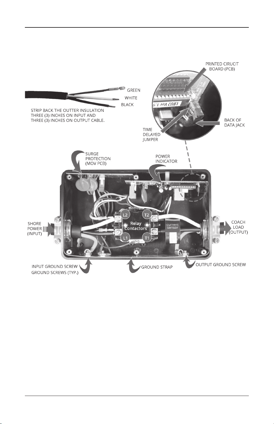
3) Cut the RV power cord about three (3) inches greater than the distance from the
junction box to the desired location of the EMS control box. Then strip back the
outer insulation three (3) inches on input, and three (3) inches on output cable.
See visual references on page 9.
4) Strip back each conductor 3/8" on both stripped ends (see visual references on
page 9) and attach ring terminals to green ground wires. If this wire is a solid
wire, do not use ring terminals. Loop the wire around the ground screw.
5) Remove the lid from the EMS. Inside the unit will be a display, cable and pack of
screws. Back o the six set screws from top of contactor (L1, L2, etc.).
6) Take your long cable with the plug end and connect it to the input side by sliding
through the wire restraint on the end of the EMS control box. Next connect the
wires to the contactor by attaching the black wire to L1, white to L2, red to L3, and
green to ground screw on side of box. See visual references on page 9. Torque
down set screws and ground nut to secure connections.
7) Take the short cable coming from the junction box by sliding it through the wire
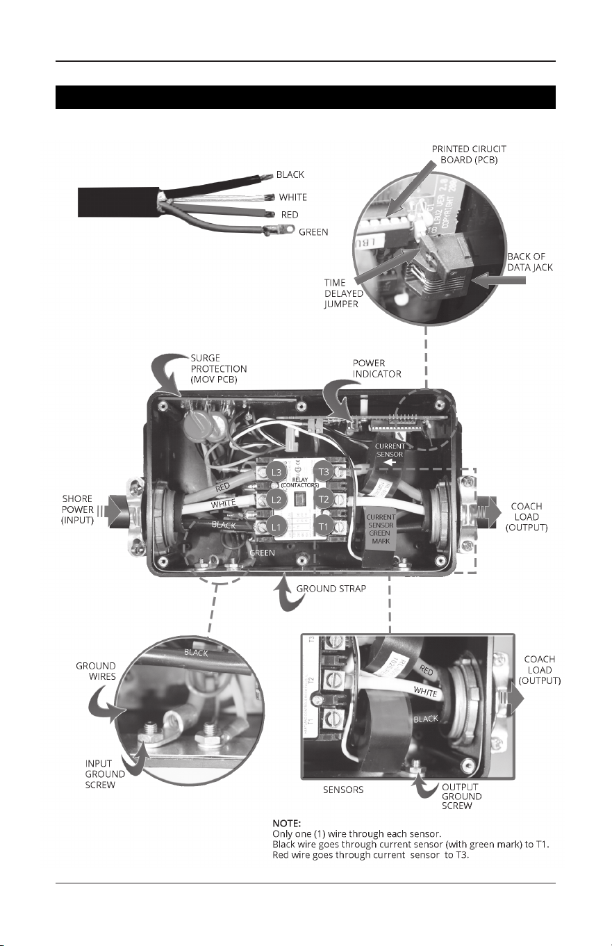
restraint output side of the EMS control box. Next slide the black wire through the
current sensor containing the green mark and connect to T1, then connect the
white wire to T2. Now slide the red wire through the other sensor and attach to T3.
The current sensor(s) can be oriented in either direction.
Attach the green ground wire to the ground screw on side of box (see visual
references on page 9). Make sure the wire colors match up adjacent to each
other. Torque down set screws and ground nut to secure connections.
8) Double check all connections and make sure they are secure.
9) Remove the two screws on contactor where marked L1, L2, etc. Next remove the
top plastic plate with markings. Examine inside ensuring there are no loose plastic
pieces inside the contactor. If so, remove and re-install cover with two screws. See
visual references on page 9. Do not over tighten screws as this could break
cover tabs.
Visual Photo Library - HW50C: page 9 | HW30C: page 10
Wiring Diagram - HW50C: page 11 | HW30C: page 11
For installation, in addition to the EMS Kit, you will need:
• 4 mounting screws.
• In some cases you will need a jumper cable, length to be
determined based on the placement of the EMS.
• Always use 10 wire for the HW30C & #6 wire for the HW50C.
Installation Instructions Before Transfer Box

ProgressiveIndustries.net | 800.307.6702
5
INSTRUCTION MANUAL:
ELECTRICAL MANAGEMENT SYSTEM (EMS)
!
CAUTION
If you break o a tab and do not remove it, this may stop the contactor
from working and allow 240 volts in the RV.
10) Secure cable ends by tightening down strain reliefs over the input and output
wires. Do not over tighten as this could cut through the insulation and cause
a short.
11) Set time delay jumper on the circuit board. The factory setting is for 15 seconds.
Remove jumper to set for 136 seconds (02:16). See Features Section on time delay
to determine which to use. See visual references on page 9.
12) Plug in remote display and cable (this cable is not a phone cable, but rather a
data cable).
NEVER PLUG IN DISPLAY WHILE RV POWER IS ON.
13) Attach EMS lid with the six black machine screws provided.
14) Mount the EMS control box.
15) Installation is complete. Next, plug in and follow operating instructions.
Visual Photo Library - HW50C: page 9 | HW30C: page 10
Wiring Diagram - HW50C: page 11 | HW30C: page 11
For installation, in addition to the EMS Kit, you will need:
• 4 mounting screws.
• In some cases you will need a jumper cable, length to be
determined based on the placement of the EMS.
• Always use 10 wire for the HW30C & #6 wire for the HW50C.
1) Unplug RV from the AC power and be sure generator is o.
2) Locate transfer switch box; determine where the EMS control box will be mounted.
3) Measure the distance between the transfer switch and the control box and add
one (1) foot. This is the length of cable that will be required for the installation.
Make sure 6-gauge, 4 conductor cables are used.
4) Remove lid from transfer box, disconnect and remove the output cable.
5) Take jumper cable and strip back one end three (3) inches and the other end the
same as the end removed from the transfer box. The cable removed from the
transfer box must have at least three (3) inches of the outer insulation removed.
See visual references on page 9.
6) Strip back all conductors 3/8" and attach ring terminals to green ground wires.
See visual references on page 9. If this wire is solid wire, do not use ring
terminals. Loop the wire around the screw.
Installation After Transfer Box for Protection
from both Generator and AC Power

ProgressiveIndustries.net | 800.307.6702
6
INSTRUCTION MANUAL: ELECTRICAL MANAGEMENT SYSTEM (EMS)
7) Remove the lid from unit. Inside the unit will be a digital display, cable and pack of
screws. Back o the six set screws from top of contactor (L1, L2, etc.).
8) Take the jumper cable and connect it to the input side by sliding through the wire
restraint on the end of the EMS control box and then connect the black wire to L1;
white to L2; red to L3, green to ground screw. See visual references on page 9.
Torque down set screws and ground nut to secure connections.
9) The cable that came from the transfer box connects to the output side of the EMS
control box in the same manner. Next slide the black wire through the current
sensor containing the green mark and connect to T1 and then connect the white
wire to T2. Now slide the red wire through the other current sensor and attach
to T3. Next, attach the green ground wire to the ground screw on the side of box.
See visual references on page 9. Make sure the conductor’s colors match up
across from each other. Torque down the set screws and ground nut to secure
connections.
10) Connect the loose end of the jumper cable to the transfer switch. See wiring
diagram on transfer switch if needed.
11) Double check all connections to ensure they are secure.
12) Secure cable ends by tightening down strain reliefs over the input and output
wires. Do not over tighten as this could bite through insulation and cause a short.
13) Set time delay jumper on the circuit board. Factory setting is for 15 seconds.
Remove jumper to change setting to 136 seconds (02:16). See Features Section on
time delay to determine which to use. See visual references on page 9.
14) Plug in digital remote and data cable (this cable is not a phone cable, but rather a
data cable.)
NEVER PLUG IN THE DISPLAY WHILE RV POWER IS ON.
15) Attach lid with the six black machine screws provided and attach transfer switch lid.
16) Mount the EMS control box.
17) Installation is complete. Next, plug in and follow operating instructions.
Operating Instructions
1) Plug into A/C power.
2) Digital display will read 888 for one second and then begin scrolling the voltage,
amps, line frequency and error code, if any. In addition, the time delay light will
ash while the EMS is going through its countdown and will stop when the unit
engages (bottom right hand corner.) If delay light does not ash, a fault condition is
present. Refer to the Error Code Chart (page 7) to determine the problem with
the AC power.
3) You may notice when rst plugging in, the display may read E 9. This indicates the
display has not received the data from the computer yet. Do not be alarmed, this is
normal. By the next scroll through, it should read E 0 if the AC power is normal.

ProgressiveIndustries.net | 800.307.6702
7
INSTRUCTION MANUAL:
ELECTRICAL MANAGEMENT SYSTEM (EMS)
4) The digital display will give you a three digit number indicating your line voltage.
Next, it will give you an “0A” reading indicating the current (amps). The current
(amps) will read zero until the time delay is complete (136 seconds or 16
seconds, depending on your settings). The output power will remain o until
the time delay is nished. Next the unit will indicate a number between 0 and 50
which indicates how many amps the RV is drawing. The next number indicates your
line frequency. This number should be “60H” and should remain fairly consistent;
however, it may read plus/minus one or two. Lastly, note the E code. E 0 is normal
and only when E 0 or E 10 is present will the delay light ash and allow power to
the RV. Refer to the Error Code Chart card that was provided with your unit or see
the Error Code Chart (page 7) for additional information.
5) Set up will be complete when the Error Code E 0 is displayed.
NOTE: If the wiring reads anything dierent than correct, the EMS will not turn on and
we recommend you move to a dierent source of AC power or use your generator
power. Also, if power is below 104 volts or above 132 volts, the EMS will not turn on,
and we recommend using your generator power.
Display Code Chart
L1 - Line 1
XXX - Line 1 Voltage
XXA - Line 1 Amps
L2 - Line 2
XXX - Line 2 Voltage
XXA - Line 2 Amps
XXH - Frequency in Hertz (Hz)
E X - Error Code
PE X - Previous Error Code that has been corrected (If Applicable).
Error Code Chart
E 0 - Normal Operating Condition
E 1 - Reverse Polarity (hot and neutral wires reversed)
E 2 - Open Ground (no ground wire connection)
E 3 - Line 1 High Voltage (line voltage above 132V)
E 4 - Line 1 Low Voltage (line voltage below 104V)
E 5*- Line 2 Voltage High (Line voltage above 132V)
E 6*- Line 2 Voltage Low (Line voltage below 104V)
E 7 - Line Frequency High (line frequency above 69Hz)
E 8 - Line Frequency Low (line frequency below 51Hz)
E 9 - Data Link Down (call technical support)
E 10 - Replace Surge Protector Module (call Progressive Industries Tech Support)
* Code only apply to EMS-HW50C models
Note: PE is a previous error code that HAS BEEN RECTIFIED.
If the EMS cuts the power to the RV it will show a PE code following the E code. This
denotes the previous error or why the EMS shut down. Example: The EMS cuts power

ProgressiveIndustries.net | 800.307.6702
8
INSTRUCTION MANUAL: ELECTRICAL MANAGEMENT SYSTEM (EMS)
for low voltage on Line 1, and then the power is restored. The Error Code reads
E0, but the PE code reads PE 4 which tells the user low voltage was the reason for
the EMS previously cutting power. This PE error code will be deleted when power is
disconnected from the EMS.
Accidental 240 volt Protection: Should this condition occur, the display will read
240 volts instead of displaying the voltage and the error code message will read E3.
AC power will shut down instantly. DO NOT UNDER ANY CIRCUMSTANCES BYPASS
THE EMS AS THIS WILL RESULT IN SEVERE DAMAGE TO THE RV.
Troubleshooting Guide
Common installation mistakes:
1) Check connections.
Visual Photo Library - HW50C: page 9 | HW30C: page 10
Wiring Diagram - HW50C: page 11 | HW30C: page 11
• HW50C: Input is the plug side of the RV and black should be attached to L1,
white to L2 and red to L3. Output (going to the RV) should match up. T1 black,
T2 white and T3 red. The green ground gets attached to the input and output
on the side of the box.
• HW30C: Input is the plug side of the RV and black should be attached to L1,
white to L2. Output (going to the RV) should match up. T1 is black, T2 white. The
green ground gets attached to the input and output on the side of the box.
2) Make sure the input wires are, in fact, the input wires. Connecting the output to the
input of the EMS will cause the device to malfunction.
3) If the EMS is still not functioning at this point, follow instructions below prior to
calling Progressive Industries Technical Support.
In order for the on-call Technician to help troubleshoot the problem(s) you are
experiencing and render the best possible solution, it is necessary you be at your RV
when you place your call. If the display is illuminated and scrolling information, note
the Error Code. If there is an Error code of 1-9, the device will interrupt the power. See
Error Chart for denition of AC power problem. The device being o when an Error
Code is present indicates the product is working properly and protecting your coach.
1) If the display is illuminated and reading Error code E 0, and yet no power is present
in the coach, please contact Progressive Industries Tech Support. You must wait for
the time delay light to stop ashing.
2) If the display is not illuminated and power is in the coach there is a connection
issue between the display and the main control box. Contact Technical Support.
Our Tech Support Team can only assist you if the above information is provided;
therefore, it is necessary for you to be at the RV when you place your call. To recap...
1) Are the connections correct?
2) What is the Error Code message being displayed?
3) Is the delay indicator ashing?
ProgressiveIndustries.net | 800.307.6702
9
INSTRUCTION MANUAL:
ELECTRICAL MANAGEMENT SYSTEM (EMS)
Visual References
Photo Library for the EMS-HW50C
ProgressiveIndustries.net | 800.307.6702
10
INSTRUCTION MANUAL: ELECTRICAL MANAGEMENT SYSTEM (EMS)
Photo Library for the EMS-HW30C
ProgressiveIndustries.net | 800.307.6702
11
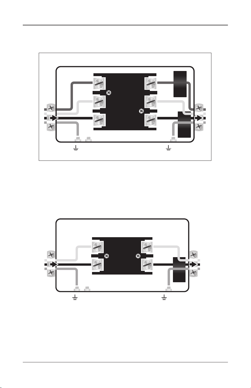
INSTRUCTION MANUAL:
ELECTRICAL MANAGEMENT SYSTEM (EMS)
Power
Input
Coach Load
Output
Black
Output
White
Output
Black
Input
Input
Ground
White
Input
Red
Input
Red
Output
L2 T2
L3 T3
L1 T1
Relay
(Contactors)
Output
Ground
Sensor
w/green
mark
Sensor
Black
Output
White
Output
Black
Input
Input
Ground
White
Input
L2 T2
L1 T1
Relay
(Contactors)
Output
Ground
Sensor
Power
Input
Coach Load
Output
Wiring Diagram for EMS-HW50C
Wiring Diagram for EMS-HW30C

INSTRUCTION MANUAL:
Electrical Management System (EMS)
EMS-HW30C & EMS-HW50C
ELECTRICAL MANAGEMENT SYSTEM (EMS)
ProgressiveIndustries.net | 800.307.6702 | ZX480/PRI-6006 (1221)
Progressive Industries, Inc.
For more information regarding the Limited Lifetime Warranty,
Troubleshooting and the Warranty Claim Form visit:
www.progressiveindustries.net
Technical Support
• 800.307.6702