Miter Saw
Model: DMS03G
ID:HM1247A
User Manual

SPECIFICATIONS
General Safety Precautions (Applicable to All Tools)
Model
Blade Diameter
Hole Diameter
Max. Miter Angle
Max. Bevel Angle
No-load Speed
0°
45°
DMS03G
12in/305mm
1in/25.4mm
Left 45°; Right 45°
Left 45°; Right 45°
3800RPM
Max. Cutting Capacities (H x W) with 305mm(12") blade
Miter Angle
Bevel Angle
45°(left) 0° 45°(Right)
"2-3/8in x 9in
(60mm x 230mm)"
2-1/4in x 9in
(33mm x 230mm)
2-3/8in x 13in
(60mm x 330mm)
2-1/4in x 13in
(33mm x 330mm)
4-1/8in x 9in
(105mm x 230mm)
4-1/8in x 13in
(105mm x 330mm)
Safety First: A Guide for Responsible Tool Operation
For Your Safety, Read the Instruction Manual Before Operating the Tool and Keep It for Future Reference
1.
2.
3.
4.
5.
6.
7.
8.
9.
10.
11.
12.
13.
14.
15.
16.
17.
18.
19.
20.
21.
22.
23.
24.
25.
Know Your Power Tool: Familiarize yourself with the owner's manual to understand the applications, limitations,
and potential hazards associated with the tool.
Keep Guards in Place: Ensure that guards are properly installed and functional during tool operation.
Remove Adjusting Keys and Wrenches: Prior to turning on the tool, habitually check and remove any adjusting
keys or wrenches.
Maintain a Clean Work Area: Prevent accidents by keeping your work area organized and free from clutter.
Use in Safe Environments: Avoid using power tools in damp, wet conditions, or in the presence of flammable
substances. Ensure proper lighting in your work area.
Keep Children Away: Maintain a safe distance between children and the work area, implementing measures like
padlocks, master switches, or removing starter keys.
Workshop Security Measures: Implement workshop security features such as padlocks or master switches to
make the workshop childproof.
Avoid Forcing the Tool: Operate the tool at the recommended rate to ensure optimal and safe performance.
Use the Right Tool: Do not force the tool or attachment to perform tasks beyond its design specifications.
Wear Proper Apparel: Avoid loose clothing, gloves, neckties, rings, bracelets, or jewelry that may get caught in
moving parts. Use nonslip footwear and protective hair coverings.
Always Use Safety Glasses: Utilize safety glasses and, if needed, a face or dust mask during dusty cutting opera-
tions. Everyday eyeglasses are not a substitute for safety glasses.
Secure Work: Use clamps or a vise to secure work, promoting a safer environment and freeing both hands for tool
operation.
Do Not Overreach: Maintain proper footing and balance at all times to prevent accidents.
Maintain Tools with Care: Keep tools sharp and clean for optimal performance. Follow instructions for lubrication
and changing accessories.
Disconnect Tools before Servicing: Always disconnect tools before servicing or changing accessories to reduce
the risk of accidents.
Prevent Unintentional Starting: Ensure the switch is in the off position before plugging in the tool.
Use Recommended Accessories: Refer to the owner's manual for recommended accessories. Improper accesso-
ries may pose a risk of injury.
Never Stand on the Tool: Serious injury may occur if the tool is tipped or if the cutting tool is unintentionally
contacted.
Check for Damaged Parts: Before further use, carefully inspect and check damaged parts to ensure proper opera-
tion and function. Repair or replace damaged parts as needed.
Direction of Feed: Feed work into a blade or cutter against the direction of rotation only.
Never Leave Tool Running Unattended: Turn off the power and wait for the tool to come to a complete stop before
leaving it unattended.
Use Identical Replacement Parts: When servicing, use only identical replacement parts to maintain the tool's
integrity.
Polarized Plugs: To reduce the risk of electric shock, use the provided polarized plug correctly. If it does not fit,
contact a qualified electrician for proper installation. Do not modify the plug.
Voltage Warning: Before connecting the tool to a power source, ensure the voltage matches the specified rating
on the tool's nameplate. Using the wrong voltage can result in serious injury and tool damage.
Use Proper Extension Cord: Ensure your extension cord is in good condition to avoid electrical hazards.
- 01 -

1.
2.
3.
4.
5.
6.
7.
8.
9.
10.
11.
12.
13.
14.
15.
16.
17.
18.
19.
20.
21.
22.
23.
24.
25.
Know Your Power Tool: Familiarize yourself with the owner's manual to understand the applications, limitations,
and potential hazards associated with the tool.
Keep Guards in Place: Ensure that guards are properly installed and functional during tool operation.
Remove Adjusting Keys and Wrenches: Prior to turning on the tool, habitually check and remove any adjusting
keys or wrenches.
Maintain a Clean Work Area: Prevent accidents by keeping your work area organized and free from clutter.
Use in Safe Environments: Avoid using power tools in damp, wet conditions, or in the presence of flammable
substances. Ensure proper lighting in your work area.
Keep Children Away: Maintain a safe distance between children and the work area, implementing measures like
padlocks, master switches, or removing starter keys.
Workshop Security Measures: Implement workshop security features such as padlocks or master switches to
make the workshop childproof.
Avoid Forcing the Tool: Operate the tool at the recommended rate to ensure optimal and safe performance.
Use the Right Tool: Do not force the tool or attachment to perform tasks beyond its design specifications.
Wear Proper Apparel: Avoid loose clothing, gloves, neckties, rings, bracelets, or jewelry that may get caught in
moving parts. Use nonslip footwear and protective hair coverings.
Always Use Safety Glasses: Utilize safety glasses and, if needed, a face or dust mask during dusty cutting opera-
tions. Everyday eyeglasses are not a substitute for safety glasses.
Secure Work: Use clamps or a vise to secure work, promoting a safer environment and freeing both hands for tool
operation.
Do Not Overreach: Maintain proper footing and balance at all times to prevent accidents.
Maintain Tools with Care: Keep tools sharp and clean for optimal performance. Follow instructions for lubrication
and changing accessories.
Disconnect Tools before Servicing: Always disconnect tools before servicing or changing accessories to reduce
the risk of accidents.
Prevent Unintentional Starting: Ensure the switch is in the off position before plugging in the tool.
Use Recommended Accessories: Refer to the owner's manual for recommended accessories. Improper accesso-
ries may pose a risk of injury.
Never Stand on the Tool: Serious injury may occur if the tool is tipped or if the cutting tool is unintentionally
contacted.
Check for Damaged Parts: Before further use, carefully inspect and check damaged parts to ensure proper opera-
tion and function. Repair or replace damaged parts as needed.
Direction of Feed: Feed work into a blade or cutter against the direction of rotation only.
Never Leave Tool Running Unattended: Turn off the power and wait for the tool to come to a complete stop before
leaving it unattended.
Use Identical Replacement Parts: When servicing, use only identical replacement parts to maintain the tool's
integrity.
Polarized Plugs: To reduce the risk of electric shock, use the provided polarized plug correctly. If it does not fit,
contact a qualified electrician for proper installation. Do not modify the plug.
Voltage Warning: Before connecting the tool to a power source, ensure the voltage matches the specified rating
on the tool's nameplate. Using the wrong voltage can result in serious injury and tool damage.
Use Proper Extension Cord: Ensure your extension cord is in good condition to avoid electrical hazards.
When employing an extension cord, ensure it possesses the capacity to accommodate the current product
demands. Using an undersized cord may lead to a decline in line voltage, resulting in power loss and over-
heating. Refer to Table 1 for appropriate cord sizes, considering both length and nameplate ampere rating. In
case of uncertainty, opt for a heavier gauge cord. Remember, the lower the gauge number, the sturdier the
cord.
Table 1: Minimum gauge for cord
Ampere Rating
More Than
0
6
10
12
No More Than
6
10
12
16
Volts
120V
18
18
16
14
16
16
16
12
16
14
14
14
12
12
25ft. 50ft. 100ft. 150ft.
Total length of cord in feet
AWG
Not Recommended
- 02 -

Additional Safety Guidelines
1.
2.
3.
4.
5.
6.
7.
8.
9.
10.
11.
12.
13.
14.
15.
16.
17.
18.
19.
20.
21.
22.
23.
24.
25.
26.
27.
Prioritize Safety: Do not allow comfort or familiarity with the product gained from repeated use to compromise
strict adherence to safety rules for the slide compound saw. Failure to use this tool safely may result in serious
personal injury.
Eye Protection: Always wear eye protection to safeguard your eyes during operation.
Hands Safety: Keep hands out of the path of the saw blade, and avoid contact with any coasting blade to prevent
severe injury.
Guard Usage: Do not operate the saw without guards in place. Ensure the blade guard closes properly before
each use, and do not clamp or force it into the open position.
Secure Workpiece: Secure the workpiece firmly against the turn base and guide fence with a vise during all opera-
tions. Never use your hand to secure the workpiece.
Avoid Reaching Around the Blade: Never reach around the saw blade, maintaining a safe distance during opera-
tion.
Power Off Before Adjusting: Turn off the tool and wait for the saw blade to stop before moving the workpiece or
making any adjustments.
Unplug Before Servicing: Unplug the tool before changing the blade or performing any maintenance.
Carriage Position: After each cross-cut operation, return the carriage to the full rear position to reduce the risk of
injury.
Tool Carrying: Always secure all moving parts before carrying the tool.
Caution with Cutter Head Lock: The stopper pin that locks the cutter head down is for carrying and storage
purposes only, not for cutting operations.
Flammable Materials: Do not use the tool in the presence of flammable liquids or gases to avoid the risk of explo-
sion and fire.
Kickback Awareness: Be vigilant for kickback during slide-out operations. If the blade begins to bind, release the
switch immediately to prevent loss of control and injury.
Use Specified Flanges: Only use flanges specified for this tool to ensure proper functionality.
Prevent Damage: Avoid damaging the arbor, flanges, and bolts to prevent blade breakage.
Secure Turn Base: Ensure the turn base is properly secured to prevent movement during operation. Fasten the
saw to a stable work platform or bench using the designated holes.
Clear Tabletop: Remove chips and small pieces from the tabletop before operation for safety.
Avoid Nails: Inspect and remove all nails from the workpiece before operation to prevent damage.
Shaft Lock Release: Ensure the shaft lock is released before turning on the switch.
Blade Clearance: Confirm that the blade does not contact the turn base in the lowest position.
Firm Handle Grip: Hold the handle firmly, noting that the saw may move up or down slightly during start-up and
stopping.
Pre-operation Blade Check: Before using the tool on an actual workpiece, let it run for a while to check for any
abnormal vibration or wobbling that may indicate poor installation or a poorly balanced blade.
Full Blade Speed: Wait until the blade attains full speed before cutting.
Immediate Stop for Abnormalities: Stop operation immediately if you notice anything abnormal.
Trigger Lock Warning: Do not attempt to lock the trigger in the "ON" position.
Stay Alert: Be alert at all times, especially during repetitive operations. Do not be lulled into a false sense of secu-
rity, as blades are unforgiving.
Recommended Accessories: Always use accessories recommended in this manual to avoid potential injuries.
28.
29.
30.
31.
Proper Body Positioning: Ensure proper positioning of your body and hands during miter saw operation for easier,
more accurate, and safer cutting. Never place hands closer than 6" (152 mm) from the blade.
Cord Maintenance: Do not abuse the cord. Never yank the cord to disconnect it from the receptacle. Keep the
cord away from heat, oil, water, and sharp objects.
Single Piece Cutting: Never stack workpieces on the tabletop to speed up cutting operations. Cut only one piece
at a time.
Material Caution: Some materials may contain toxic chemicals. Take caution to prevent dust inhalation and skin
contact. Follow the safety data provided by the material supplier.
- 03 -
ADDITIONAL SAFETY GUIDELINES FOR THE LASER
1.
2.
3.
4.
5.
6.
7.
8.
9.
10.
11.
12.
13.
14.
15.
16.
17.
18.
19.
20.
21.
22.
23.
24.
25.
26.
27.
Prioritize Safety: Do not allow comfort or familiarity with the product gained from repeated use to compromise
strict adherence to safety rules for the slide compound saw. Failure to use this tool safely may result in serious
personal injury.
Eye Protection: Always wear eye protection to safeguard your eyes during operation.
Hands Safety: Keep hands out of the path of the saw blade, and avoid contact with any coasting blade to prevent
severe injury.
Guard Usage: Do not operate the saw without guards in place. Ensure the blade guard closes properly before
each use, and do not clamp or force it into the open position.
Secure Workpiece: Secure the workpiece firmly against the turn base and guide fence with a vise during all opera-
tions. Never use your hand to secure the workpiece.
Avoid Reaching Around the Blade: Never reach around the saw blade, maintaining a safe distance during opera-
tion.
Power Off Before Adjusting: Turn off the tool and wait for the saw blade to stop before moving the workpiece or
making any adjustments.
Unplug Before Servicing: Unplug the tool before changing the blade or performing any maintenance.
Carriage Position: After each cross-cut operation, return the carriage to the full rear position to reduce the risk of
injury.
Tool Carrying: Always secure all moving parts before carrying the tool.
Caution with Cutter Head Lock: The stopper pin that locks the cutter head down is for carrying and storage
purposes only, not for cutting operations.
Flammable Materials: Do not use the tool in the presence of flammable liquids or gases to avoid the risk of explo-
sion and fire.
Kickback Awareness: Be vigilant for kickback during slide-out operations. If the blade begins to bind, release the
switch immediately to prevent loss of control and injury.
Use Specified Flanges: Only use flanges specified for this tool to ensure proper functionality.
Prevent Damage: Avoid damaging the arbor, flanges, and bolts to prevent blade breakage.
Secure Turn Base: Ensure the turn base is properly secured to prevent movement during operation. Fasten the
saw to a stable work platform or bench using the designated holes.
Clear Tabletop: Remove chips and small pieces from the tabletop before operation for safety.
Avoid Nails: Inspect and remove all nails from the workpiece before operation to prevent damage.
Shaft Lock Release: Ensure the shaft lock is released before turning on the switch.
Blade Clearance: Confirm that the blade does not contact the turn base in the lowest position.
Firm Handle Grip: Hold the handle firmly, noting that the saw may move up or down slightly during start-up and
stopping.
Pre-operation Blade Check: Before using the tool on an actual workpiece, let it run for a while to check for any
abnormal vibration or wobbling that may indicate poor installation or a poorly balanced blade.
Full Blade Speed: Wait until the blade attains full speed before cutting.
Immediate Stop for Abnormalities: Stop operation immediately if you notice anything abnormal.
Trigger Lock Warning: Do not attempt to lock the trigger in the "ON" position.
Stay Alert: Be alert at all times, especially during repetitive operations. Do not be lulled into a false sense of secu-
rity, as blades are unforgiving.
Recommended Accessories: Always use accessories recommended in this manual to avoid potential injuries.
28.
29.
30.
31.
Proper Body Positioning: Ensure proper positioning of your body and hands during miter saw operation for easier,
more accurate, and safer cutting. Never place hands closer than 6" (152 mm) from the blade.
Cord Maintenance: Do not abuse the cord. Never yank the cord to disconnect it from the receptacle. Keep the
cord away from heat, oil, water, and sharp objects.
Single Piece Cutting: Never stack workpieces on the tabletop to speed up cutting operations. Cut only one piece
at a time.
Material Caution: Some materials may contain toxic chemicals. Take caution to prevent dust inhalation and skin
contact. Follow the safety data provided by the material supplier.
ALWAYS PERFORM DRY RUNS (UNPOWERED)
BEFORE FINISH CUTS TO CHECK THE BLADE'S
PATH. DO NOT CROSS ARMS DURING OPERA-
TION.
SAFETY ALERT: SAVE THESE INSTRUCTIONS!
Failure to adhere to the safety rules outlined in this instruction manual may result in serious personal
injury. Misuse or disregard of these guidelines is strictly cautioned.
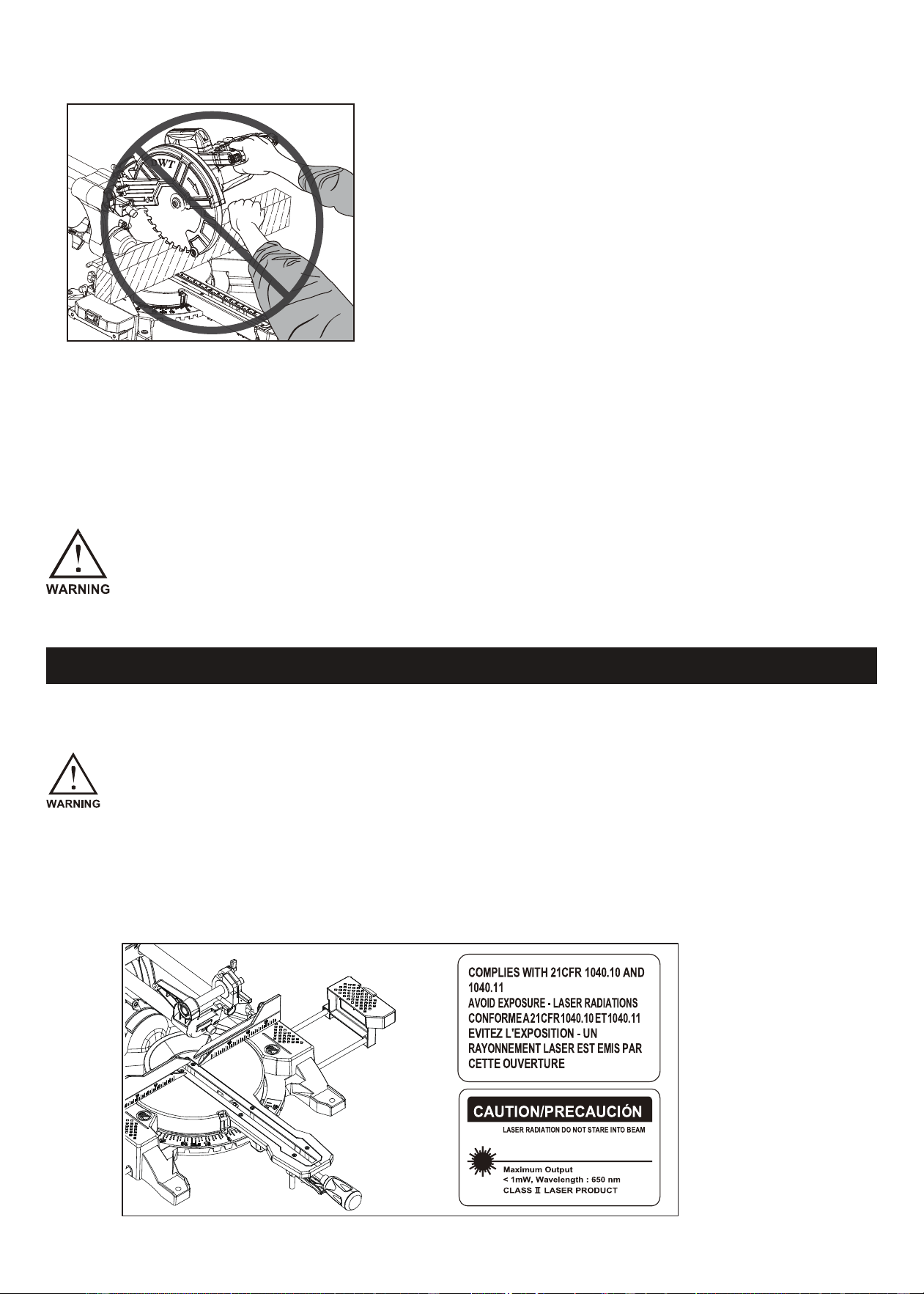
CAUTION: LASER RADIATION - AVOID DIRECT EYE EXPOSURE.
DO NOT STARE INTO BEAM. Laser radiation poses a risk to eyesight; avoid direct exposure to the
laser beam.
AVOID EXPOSURE. Laser radiation is emitted from the aperture; exercise caution to prevent direct
exposure.
CONTROL USAGE CAUTION. The use of controls, adjustments, or procedures not explicitly speci-
fied in this manual may result in hazardous radiation exposure.
Prioritize safety and strictly adhere to the specified guidelines to minimize the risk of laser radia-
tion exposure.
RADIACIÓN LÁSER NO DIRIJA LA
VISTA HACIA EL RAYO LÁSER
- 04 -
INSTALLATION
FUNCTIONAL DESCRIPTION:
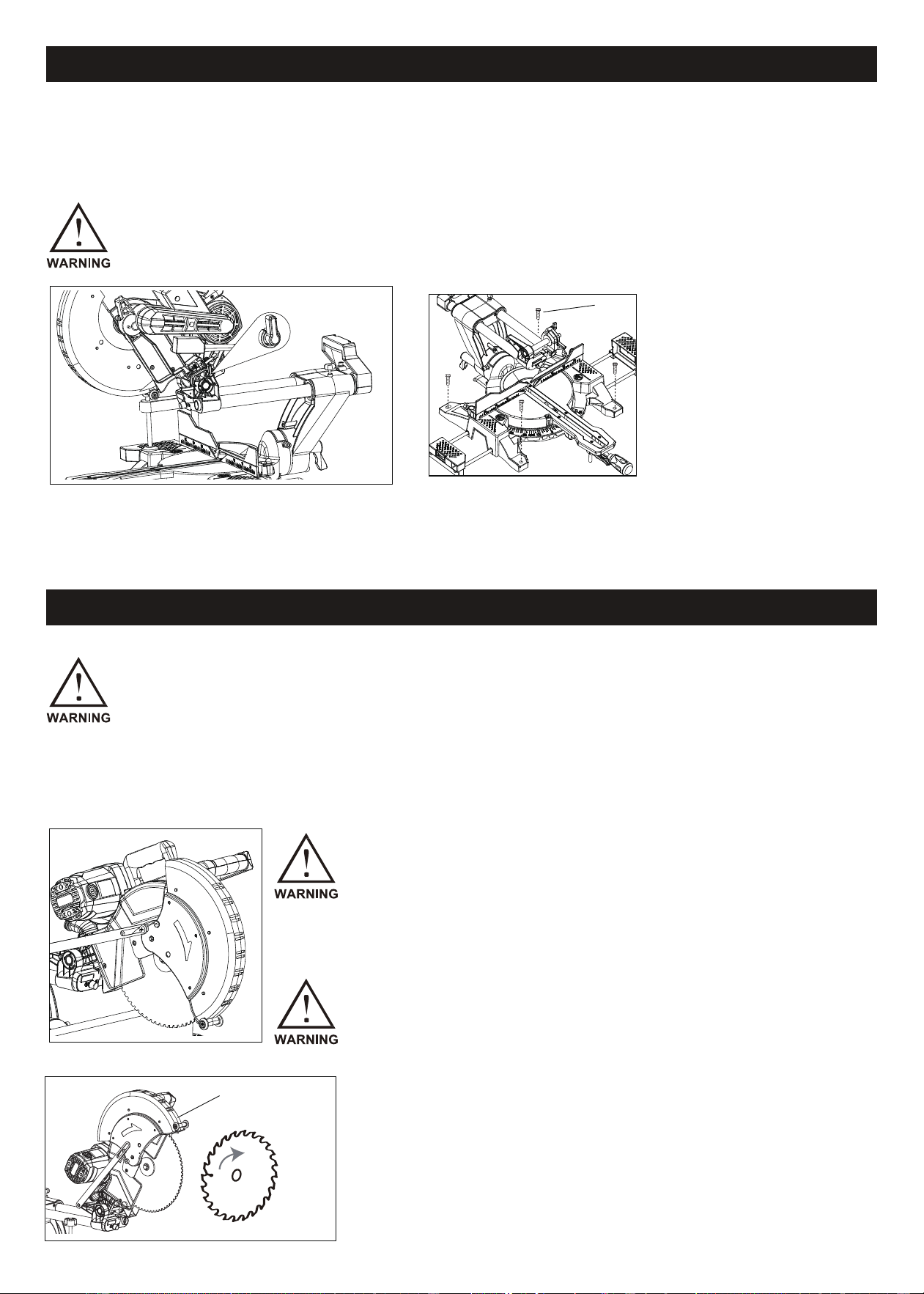
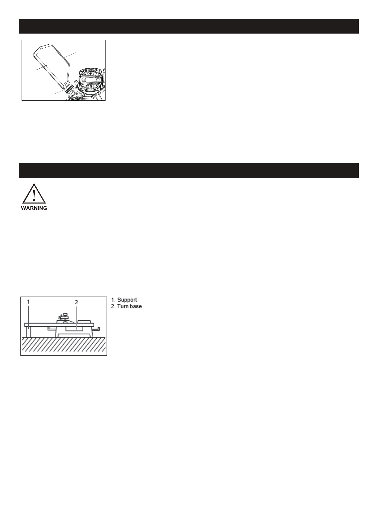
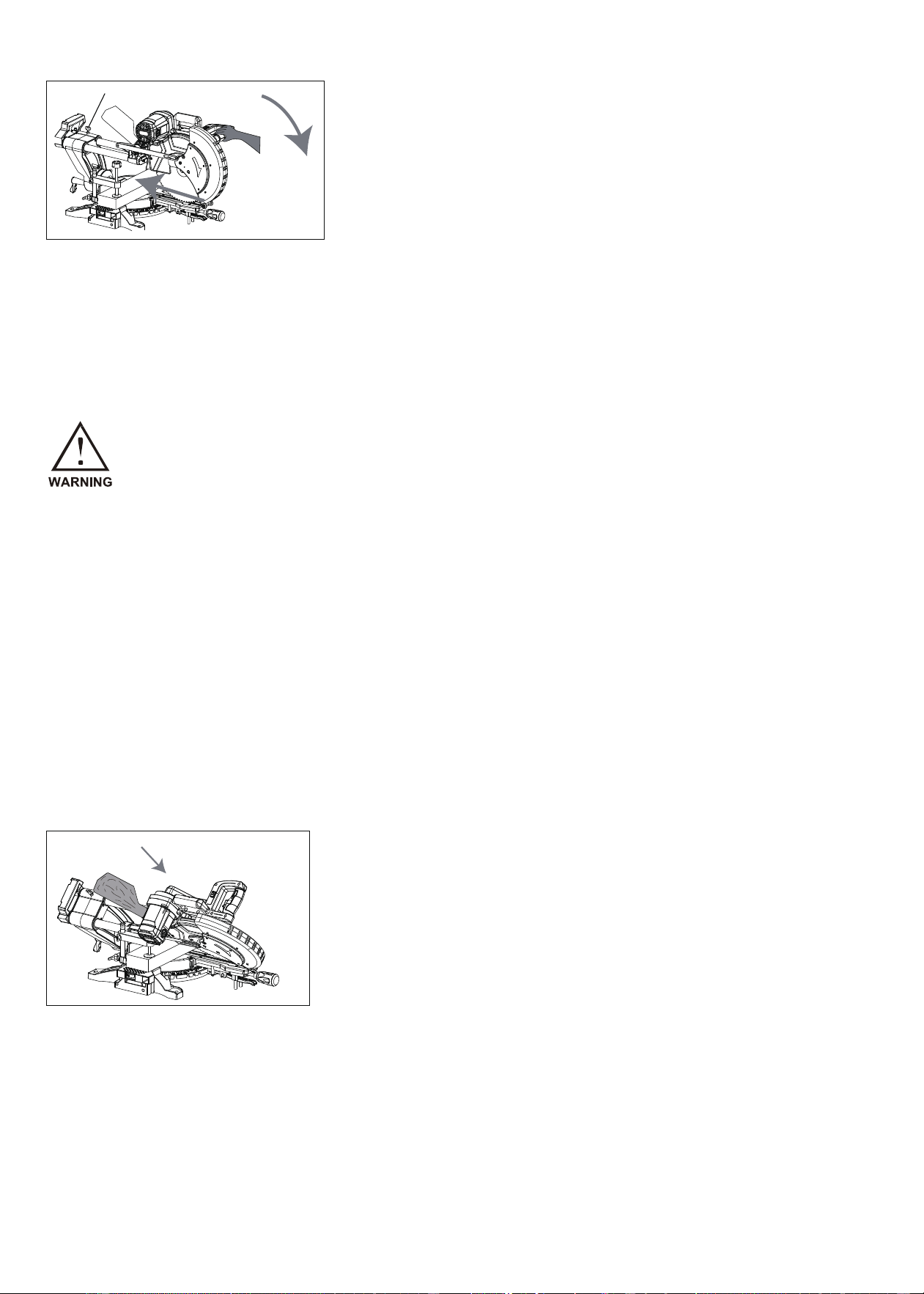
Bench Mounting:
Upon receiving the tool, the handle is secured in the lowered position by the stopper pin. Release the stopper pin by
applying a slight downward pressure on the handle while pulling the stopper pin.
For secure installation, bolt the miter saw with four bolts to a level and stable surface using the provided bolt holes in
the tool's base. This step is crucial to prevent tipping and potential injury.
Blade Guard:
When lowering the handle, the blade guard automatically rises, returning to its original position when the cut is com-
plete and the handle is raised.
Ensure absolute stability on the supporting surface to prevent any movement
during operation.
Any unintended movement during cutting can lead to loss of control and serious personal injury.
Prior to adjusting or checking the tool's function, always ensure the tool is switched off and unplugged.
Failure to power off and unplug the tool may result in serious personal injury due to accidental start-up.
Take necessary precautions to guarantee a safe working environment.
Never disable or remove the blade guard or its attached spring.
Operating the tool with an exposed blade due to disabled guarding may
result in serious personal injury during operation.
Do not use the tool if the blade guard or spring is damaged, faulty, or
removed, as this may lead to serious personal injury.
For your safety, always keep the blade guard in optimal condition. Promptly correct
any irregular operation of the blade guard and ensure its spring-loaded return action
is functional.
Stopper pin
Bolts
In case the see-through blade guard becomes dirty, or sawdust
adheres to it, obstructing the clear view of the blade and/or work-
piece, unplug the saw and carefully clean the guard with a damp
cloth. Avoid using solvents or petroleum-based cleaners on the
plastic guard to prevent damage.
Blade guard
- 05 -
Maintaining Maximum Cutting Capacity
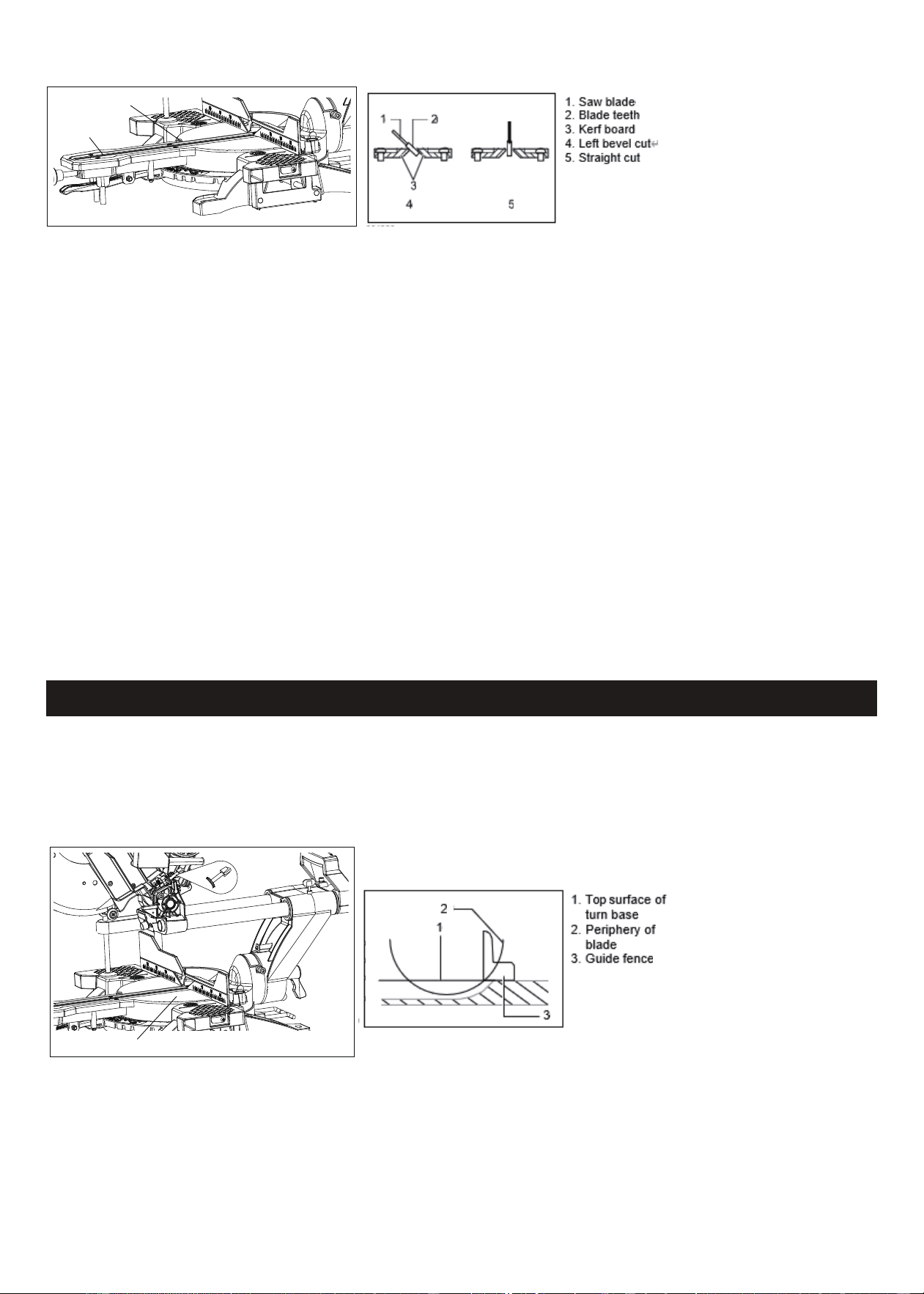
Positioning Kerf Board:
The tool is equipped with kerf boards in the turn base to minimize tearing on the exit side of a cut. These kerf boards
come factory-adjusted to ensure the saw blade does not contact them.
Before use, adjust the kerf boards as follows:
1. Unplug the tool.
2. Loosen all screws (3 each on the left and right) securing the kerf boards, tightening them only enough to allow easy
manual movement of the kerf boards.
3. Lower the handle fully and lock it in the lower position with the stopper pin.
4. Loosen the screw securing the slide poles. Pull the carriage fully toward you.
5. Adjust the kerf boards to just contact the sides of the blade teeth. Tighten the front screws (do not overtighten).
6. Push the carriage fully toward the guide fence, adjusting the kerf boards to just contact the sides of the blade teeth.
Tighten the rear screws (do not overtighten).
7. After adjusting the kerf boards, release the stopper pin, raise the handle, and securely tighten all the screws.
NOTICE:
After setting the bevel angle, ensure proper adjustment of the kerf boards. Correctly adjusted kerf boards provide
adequate support for the workpiece, minimizing tear-out during cutting.
This tool comes from the factory with optimal adjustments to provide the maximum cutting capacity for a 12-in-
ch/305mm saw blade.
Ensure the tool is unplugged before attempting any adjustments. When installing a new blade, follow these steps to
check and, if necessary, adjust the lower limit position of the blade:
With the tool unplugged, manually rotate the blade while holding the handle down to ensure the blade does not
contact any part of the lower base. Re-adjust slightly if necessary.
Screw
Kerf board
Adjusting bolt
Turn base
1. Unplug the tool.
2. Push the carriage toward the guide fence and lower the handle completely.
3. Use the hex wrench to turn the adjusting bolt until the periphery of the blade extends slightly below the top surface
of the turn base at the point where the front face of the guide fence meets the top surface of the turn base.
- 06 -
Adjusting the Bevel Angle
Always confirm that the blade does not touch any part of the lower base when the handle is lowered
completely after installing a new blade. Blade contact with the base may lead to kickback and result in
serious personal injury.
CAUTION:
Always secure the turn base by firmly tightening the
grip after changing the miter angle.
NOTICE:
When turning the turn base, ensure the handle is fully
raised for proper operation.
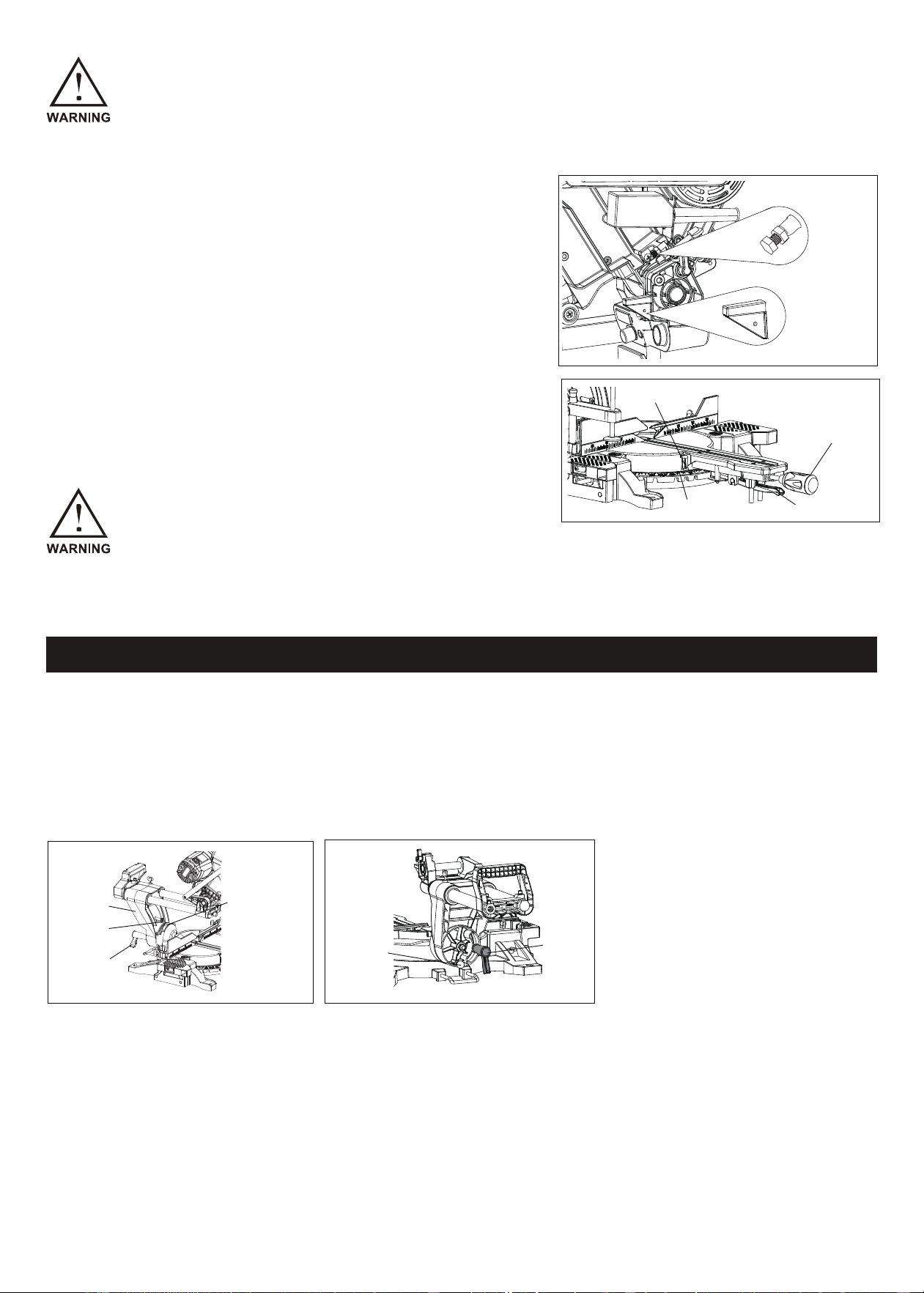
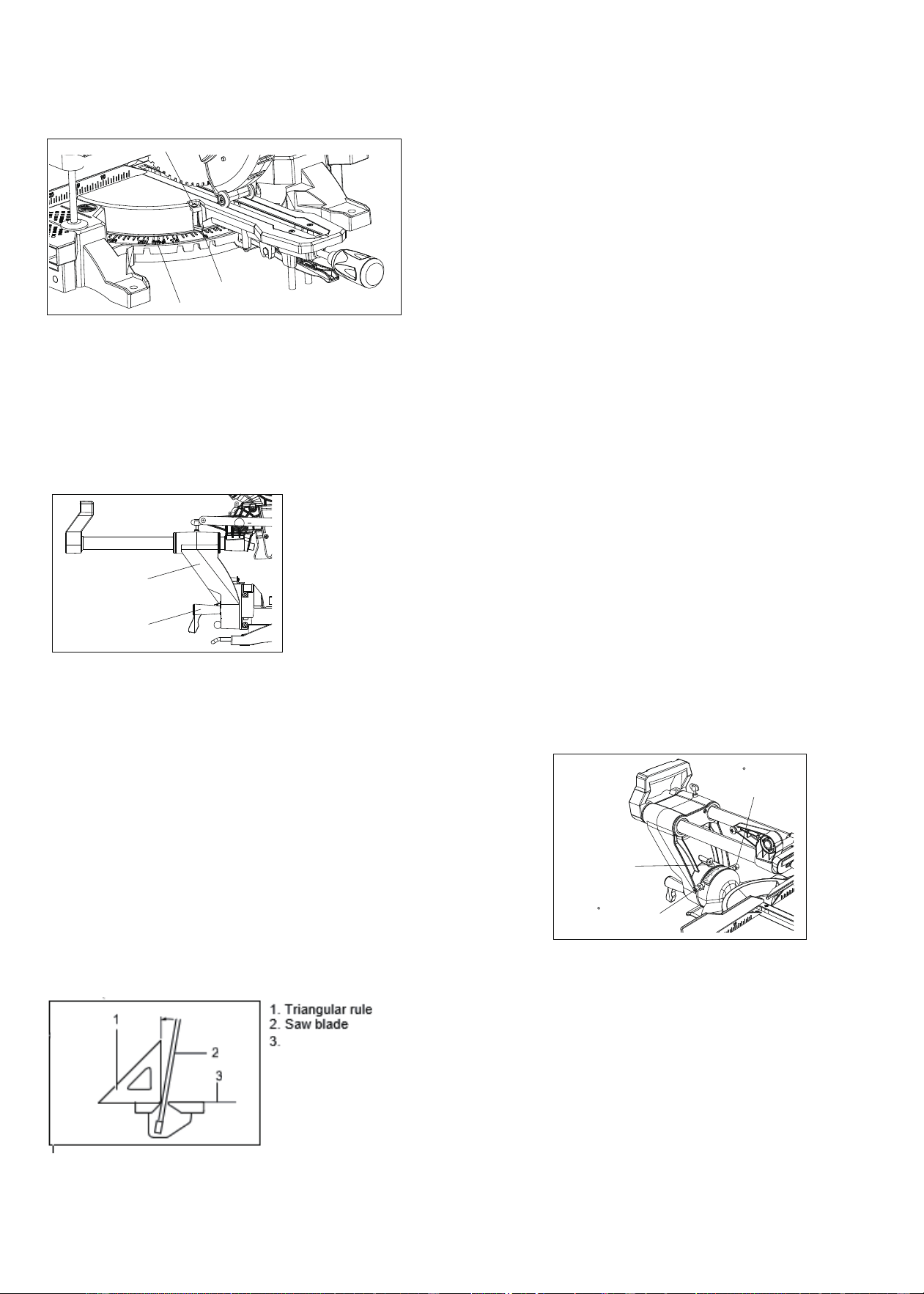
Stopper Arm:
Easily adjust the lower limit position of the blade with the stopper
arm. To adjust, move the stopper arm in the direction of the arrow
shown in the figure. Set the adjusting screw so that the blade stops
at the desired position when lowering the handle fully.
Adjusting the Miter Angle:
Loosen the grip by turning counterclockwise.
Turn the turn base while pressing down the lock lever.
Move the grip to the position where the pointer aligns with the
desired angle on the miter scale.
Securely tighten the grip clockwise.
stopper arm
Adjusting screw
Miter scale
lock lever
grip
pointer
Note: The lever can be adjusted to a different angle by removing the screw holding it and securing the lever at the
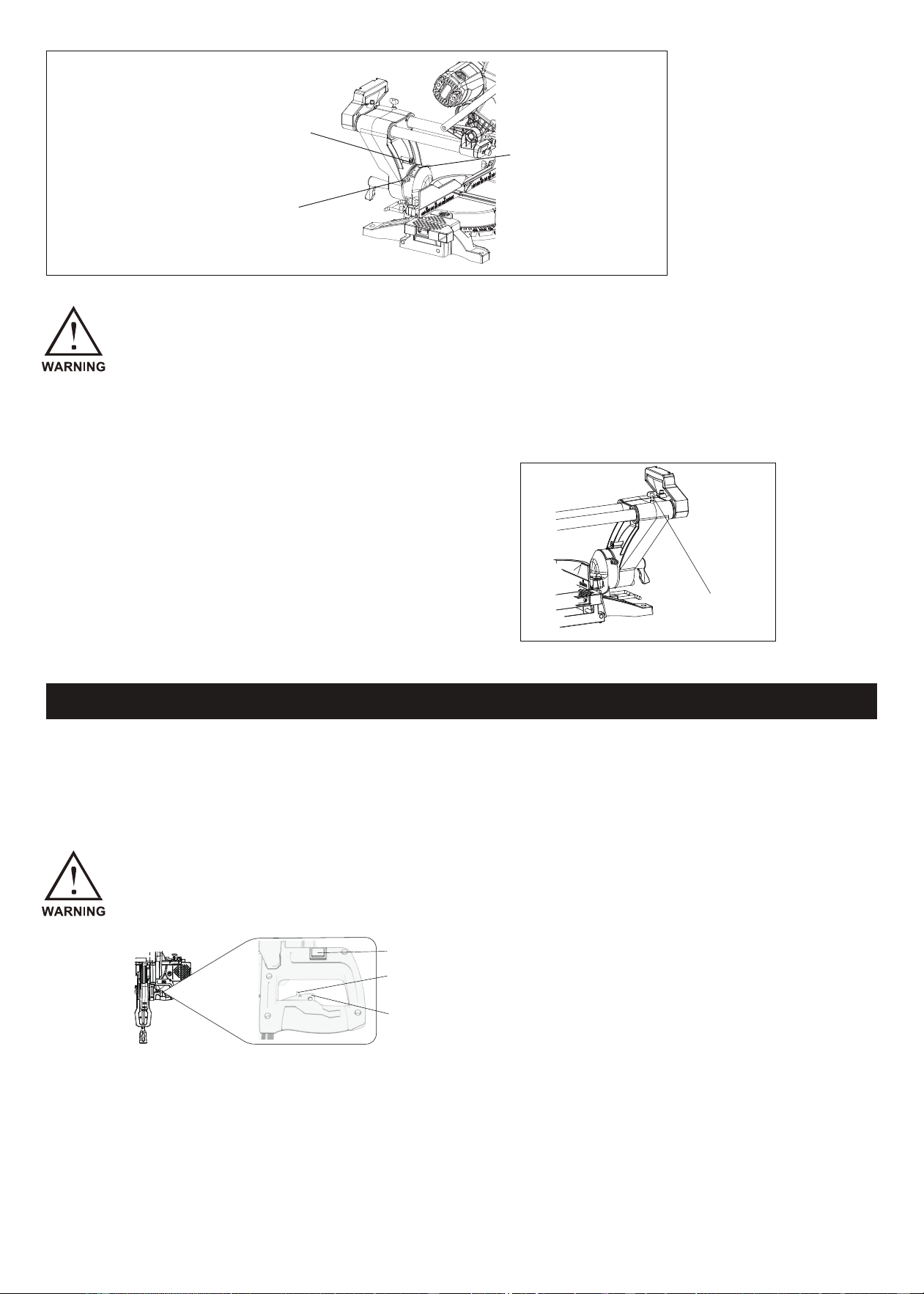
To modify the bevel angle, follow these steps:
Loosen the lever at the rear of the tool counterclockwise.
Unlock the arm by firmly pushing the handle in the direction you intend to tilt the saw blade.
desired angle.
Note: To tilt to the right, pull out the lock pin first and then tilt to the right. If not tilting to the right, push the locking shaft
Tilt the saw blade until the pointer aligns with the desired angle on the bevel scale.
Firmly tighten the lever clockwise to secure the arm.
back to its original position.
bevel scale
lever
pointer
arm
lever
lock pin
- 07 -
Switch Action
CAUTION:
After adjusting the bevel angle, always secure the arm by tightening the lever clockwise.
Before plugging in the tool, always check that the switch trigger actuates properly and returns to the
"OFF" position when released. Avoid pulling the switch trigger hard without pressing the lock-off button
to prevent switch breakage. Operating a tool with a malfunctioning switch can lead to loss of control and
serious injury.
NOTICE:
Ensure the handle is fully raised when tilting the saw blade. When changing bevel angles, position the kerf boards
appropriately, as explained in the "Positioning Kerf Boards" section.
To prevent accidental pulling of the switch trigger, a lock-off button is provided. Follow these steps:
To start the tool, press the lock-off button and pull the switch trigger.
To stop, release the switch trigger.
Never use the tool without a fully operative switch trigger. An inoperative switch is highly dangerous and must be
repaired before further use to avoid serious personal injury.
For safety, the tool is equipped with a lock-off button to prevent unintended starting.
Never use the tool if it runs by simply pulling the switch trigger without pressing the lock-off button.
A switch in need of repair may result in unintentional operation and serious injury. Contact us for repairs.
Never defeat the lock-off button by taping it down or using other means, as a switch with a defeated lock-off button
may lead to unintentional operation and serious personal injury.
Slide Lock Adjustment:
To lock the slide pole, turn the locking screw clockwise.
pointer
Release button
Bevel scale
locking screw
switch for laser
lock-off button
switch trigger
- 08 -
Laser Beam Action
Cleaning of the Lens for the Laser Light
ASSEMBLY
Installing or Removing Saw Blade
CAUTION:
Turn off the laser when not in use.
CAUTION:LASER RADIATION – DO NOT
STARE INTO BEAM.
Before shifting the laser line or performing
maintenance adjustments, unplug the tool.
Before You Begin:
Ensure that the tool is switched off and unplugged to prevent accidental start-up and potential injury.
To switch on the laser beam, press the switch position to the right (I); to switch it off, press the switch position to the left
(O). The laser line is factory-adjusted to be within 1mm (0.04in) from the side surface of the blade (cutting position).
NOTE: If the laser line is dim or hard to see due to direct sunlight, relocate the work area to a place with less direct
sunlight.
If the lens for the laser light gets dirty or sawdust adheres to it, making the laser line less visible, unplug the saw and
carefully clean the lens with a damp, soft cloth. Avoid using solvents or petroleum-based cleaners on the lens.
NOTE: If the laser line is dim or almost invisible due to direct sunlight, relocate the work area to a place not exposed
to sunlight.
Always ensure that the tool is switched off and unplugged before working on it to prevent serious personal injury.
Lock the handle in the raised position using the stopper pin.
switch for laser
1. Stopper pin
2. spind lock
1
2
3
- 09 -
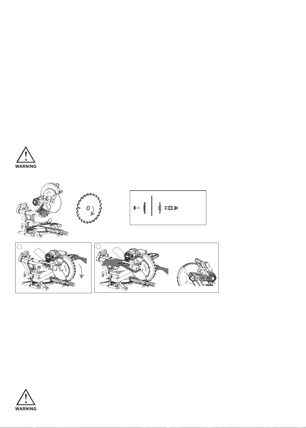
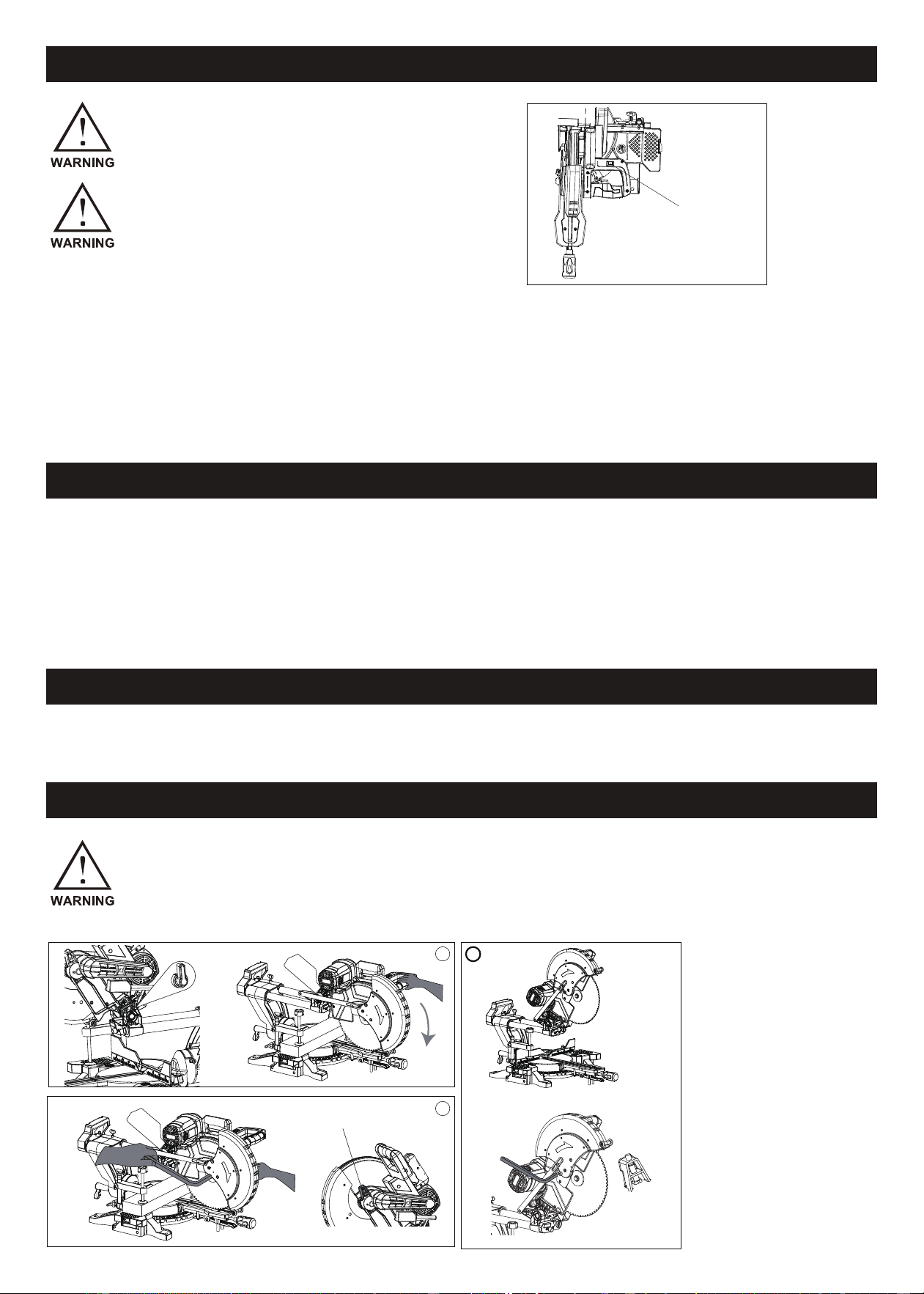
Removing the Saw Blade:
1. Press the machine head downward, utilizing the stopper pin (1) to secure the machine in place (see Figure 1).
2. In Figure 2, with the machine fixed, press and hold the spindle lock (2) with your right hand to stabilize the main shaft.
Simultaneously, use your left hand to loosen the hexagonal head bolt clockwise with the hexagonal wrench.
3. Before proceeding to step 3, pull out the stopper pin (1). Then, raise the machine head to the highest position. Lift the
transparent cover with your right hand, keeping it continuously elevated. Unscrew the loose hex head bolt with your left
hand, and remove the outer pressure plate and the saw blade.
Warning:
Ensure that before reaching step 3, the machine head is not raised to the highest position to prevent the hex head bolt
from fully unscrewing, preventing the blade from falling and causing injury.
Carefully mount the blade onto the spindle, ensuring the arrow on the blade aligns with the arrow on the blade case.
Install the outer flange and hex bolt. Use a left-handed socket wrench to securely tighten the hex bolt counterclockwise
Note:
If the inner flange is removed, install it on the spindle with its protrusion facing away from the blade. Incorrect installation
may cause rubbing against the machine.
while pressing the shaft lock.
To Install the Saw Blade:
1. Position the machine head at the highest point. Lift the transparent shield with your right hand and keep it raised.
Using your left hand, install the inner flange, saw blade, cutter flange, and hex bolt. Turn the screws counterclockwise
by hand.
2. Refer to Figure 4: Press the machine head down, using the stopper pin (1) to secure the machine.
3. Refer to Figure 5: Press and hold the spindle lock (2) with your right hand to stabilize the main shaft. Use the hexagon
wrench to tighten the screw counterclockwise with your left hand.、
Before Mounting the Blade:
Always confirm that the correct ring for the blade's arbor hole is installed between the inner and outer
flanges. The use of an incorrect arbor hole ring may lead to improper blade mounting, causing move-
ment and vibrations, potentially resulting in a loss of control during operation and serious personal injury.
Warning:
After lifting the transparent cover, ensure it remains still to prevent it from falling and causing injury when
changing the saw blade.
1. Hex bolt
2.Outer flange
3.Saw blade
4.Inner flange
5.Spindle
1 2 3 4 5
4
5
- 10 -
Use the dust bag for cleaner cutting operations and easier dust collection. Attach the dust bag onto the dust nozzle.
When the dust bag is halfway full, empty its contents by tapping it lightly to remove particles that may hinder further
collection.
Note: Connecting a vacuum cleaner to your saw allows for cleaner operations.
After a cutting operation, do not raise the blade until it comes to a complete stop to avoid personal injury and workpiece
damage.
When cutting a workpiece longer than the support base, support the material along its entire length, maintaining the
same height to keep it level.
Proper workpiece support helps avoid blade pinch and possible kickback, reducing the risk of serious injury. Do not
solely rely on the vertical or horizontal vise for thin materials, as they may sag. Support the workpiece over its entire
length to prevent blade pinch and possible kickback.
Dust Bag
Securing Workpiece
1. Dust nozzle
2. Dust bag
3. Zipper
1
2
3
Warning: Always secure the workpiece correctly with the appropriate vise or crown molding stop-
pers to prevent personal injury and tool or workpiece damage.
- 11 -
Vertical Vise Installation
Guide Fence (Sliding Fences) Adjustment
Caution:
Before operating the tool, ensure the sliding fence is securely fastened.
sliding fence
sliding fence
clamping screw
Preventing Contact during Bevel-Cutting:
1. Before engaging in bevel-cutting, confirm that no part of the tool makes contact with the sliding fence.
2. Take care when fully lowering and raising the handle in any position and while moving the carriage through its entire
range of travel.
Caution for Bevel Cuts:
When executing bevel cuts, slide the sliding fence to the left and secure it, as depicted in the figure.
Default Position for Sliding Fence:
The tool comes equipped with the sliding fence positioned as shown in the figure.
For left bevel cuts, adjust it to the left position if the tool head contacts it.
After completing bevel-cutting operations, ensure to return the sliding fence to its original position and firmly secure it by
tightening the clamping screw.
The vertical vise can be installed on either side of the guide fence. Insert the vise rod into the hole in the guide fence
and tighten the screw on the back to secure it.
Position the vise arm according to the workpiece thickness and shape. Secure the vise arm by tightening the screw. If
the screw contacts the guide fence, install it on the opposite side of the vise arm.
Ensure no part of the tool contacts the vise when fully lowering the handle or moving the carriage. If contact occurs,
reposition the vise.
Press the workpiece flat against the guide fence and the turn base. Secure it by tightening the vise knob.
Firmly secure the workpiece against the turn base and guide fence during all operations to prevent material movement,
blade damage, and loss of control.
Vise arm
Vise knob
Vise rod
Screw
Guide fence
- 12 -
2. Slide (Push) Cutting (Cutting Wide Workpieces)
Loosen the locking screw counterclockwise to allow the carriage to slide freely.
Secure the workpiece with the appropriate vise. Pull the carriage fully toward you, switch on the tool, and wait for the
blade to reach full speed.
Press the handle down and push the carriage toward the guide fence through the workpiece.
After completing the cut, switch off the tool and wait until the blade comes to a complete stop before raising it.
NOTE:
Never attempt a slide cut by pulling the carriage toward you, as it may result in unexpected kickback and serious
injury.
Do not perform a slide cut with the handle locked in the lowered position.
Never loosen the locking screw securing the carriage while the blade is rotating, as a loose carriage during cutting
may cause unexpected kickback and serious personal injury.
3. Miter Cutting
Refer to the previously covered "Adjusting the miter angle" for instructions on miter cutting.
4. Bevel Cutting
Loosen the lever and tilt the saw blade to set the bevel angle (refer to "Adjusting the bevel angle"). Ensure the lever
is firmly retightened to secure the selected bevel angle.
Secure the workpiece with a vise, ensuring the carriage is pulled all the way back toward the operator.
Switch on the tool without the blade making contact and wait for it to reach full speed.
Gently lower the handle to the fully lowered position, applying pressure parallel to the blade. Push the carriage toward
the guide fence to cut the workpiece.
After completing the cut, switch off the tool and wait until the blade comes to a complete stop before raising it.
Holders
Operation
Firmly tighten the knob clockwise to prevent carriage movement during operation. Insufficient tightening
may lead to possible kickback and serious personal injury.
The clamps on both sides extend the horizontal clamping for workpieces. Loosen the screws, pull out the clamps, and
then tighten the screws.
Support a long workpiece to be level with the top surface of the turn base for accurate cutting and to prevent danger-
ous loss of tool control.
NOTICE:
• Before use, release the handle from the lowered position by pulling the stopper pin.
• Avoid excessive pressure on the handle during cutting to prevent motor overload and maintain cutting efficiency.
• Gently press down the handle for smooth cutting without a significant decrease in blade speed.
• During a slide cut, gently push the carriage toward the guide fence without stopping to avoid marks on the work-
piece and maintain cut precision.
• Ensure the blade is not in contact with the workpiece before turning on the tool to prevent kickback and injury.
1. Press Cutting (Cutting Small Workpieces)
• For workpieces up to 60 mm (2-3/8") high, push the carriage fully toward the guide fence and tighten the locking
screw clockwise to secure it.
• Secure the workpiece with the appropriate vise. Switch on the tool without the blade making contact and wait until
it reaches full speed before lowering the handle.
• Gently lower the handle to the fully lowered position to cut the workpiece.
• After completing the cut, switch off the tool and WAIT UNTIL THE BLADE COMES TO A COMPLETE STOP
before raising it.
Locking screw
- 13 -
2. Slide (Push) Cutting (Cutting Wide Workpieces)
Loosen the locking screw counterclockwise to allow the carriage to slide freely.
Secure the workpiece with the appropriate vise. Pull the carriage fully toward you, switch on the tool, and wait for the
blade to reach full speed.
Press the handle down and push the carriage toward the guide fence through the workpiece.
After completing the cut, switch off the tool and wait until the blade comes to a complete stop before raising it.
NOTE:
Never attempt a slide cut by pulling the carriage toward you, as it may result in unexpected kickback and serious
injury.
Do not perform a slide cut with the handle locked in the lowered position.
Never loosen the locking screw securing the carriage while the blade is rotating, as a loose carriage during cutting
may cause unexpected kickback and serious personal injury.
3. Miter Cutting
Refer to the previously covered "Adjusting the miter angle" for instructions on miter cutting.
4. Bevel Cutting
Loosen the lever and tilt the saw blade to set the bevel angle (refer to "Adjusting the bevel angle"). Ensure the lever
is firmly retightened to secure the selected bevel angle.
Secure the workpiece with a vise, ensuring the carriage is pulled all the way back toward the operator.
Switch on the tool without the blade making contact and wait for it to reach full speed.
Gently lower the handle to the fully lowered position, applying pressure parallel to the blade. Push the carriage toward
the guide fence to cut the workpiece.
After completing the cut, switch off the tool and wait until the blade comes to a complete stop before raising it.
When performing a slide cut, ensure the carriage is pulled fully toward you before pushing it toward the
guide fence. Never start the cut without pulling the carriage fully toward you to avoid unexpected
kickback.
The clamps on both sides extend the horizontal clamping for workpieces. Loosen the screws, pull out the clamps, and
then tighten the screws.
Support a long workpiece to be level with the top surface of the turn base for accurate cutting and to prevent danger-
ous loss of tool control.
NOTICE:
• Before use, release the handle from the lowered position by pulling the stopper pin.
• Avoid excessive pressure on the handle during cutting to prevent motor overload and maintain cutting efficiency.
• Gently press down the handle for smooth cutting without a significant decrease in blade speed.
• During a slide cut, gently push the carriage toward the guide fence without stopping to avoid marks on the work-
piece and maintain cut precision.
• Ensure the blade is not in contact with the workpiece before turning on the tool to prevent kickback and injury.
1. Press Cutting (Cutting Small Workpieces)
• For workpieces up to 60 mm (2-3/8") high, push the carriage fully toward the guide fence and tighten the locking
screw clockwise to secure it.
• Secure the workpiece with the appropriate vise. Switch on the tool without the blade making contact and wait until
it reaches full speed before lowering the handle.
• Gently lower the handle to the fully lowered position to cut the workpiece.
• After completing the cut, switch off the tool and WAIT UNTIL THE BLADE COMES TO A COMPLETE STOP
before raising it.
Locking screw
- 14 -

NOTICE:
• When pressing down the handle, apply pressure parallel to the blade to maintain the precision of the cut.
• Before bevel-cutting, check and adjust the sliding fence if necessary (refer to "Guide fence adjustment").
5. Compound Cutting
Compound cutting involves making a bevel angle simultaneously with a miter angle on a workpiece. Refer to the
explanations for "Press Cutting", "Slide Cutting", "Miter Cutting", and "Bevel Cutting" when performing compound
cutting.
Compound cutting can be executed at the angle specified in the table provided.
6. Cutting Aluminum Extrusion
When securing aluminum extrusions, use spacer blocks or pieces of scrap as shown in the figure to prevent deforma-
tion of the aluminum.
Utilize a cutting lubricant when cutting the aluminum extrusion to prevent material build-up on the blade.
7. Groove Cutting
Note:
Before operating the tool, ensure that the carriage and blade have free travel throughout the entire range
of the intended cut to prevent kickback and injury.
Keep hands out of the blade path during a bevel cut, as the angle may confuse the operator about the
actual blade path.
Do not raise the blade until it has come to a complete stop to avoid ejecting the cut-off piece and potential
injury.
Miter Angle
0°-45° (Left and Right)
Bevel Angle
1. Guide fence
2. Vise
3. Spacer block
4. Aluminum extrusion
5. Spacer block
1. cut grooves with blade
For dado-type cuts, adjust the lower limit position of the blade using
the adjusting screw and stopper arm to control the cutting depth
(refer to the "Stopper arm" section).
After adjusting the lower limit position, make parallel grooves across
the width of the workpiece using a slide (push) cut, as illustrated.
After adjusting the lower limit position of the blade, cut parallel grooves across the width of the workpiece using a
slide (push) cut as shown in the figure.
Remove the material between the grooves with a chisel.
- 15 -

CAUTION:
Do not attempt to perform this cut with a wider blade or dado blade, as it may lead to unexpected cutting
results and kickback, causing serious personal injury.
The stopper pin is designated solely for carrying and storage purposes and must never be employed
during cutting operations.
Using the stopper pin for cutting can lead to unexpected blade movement, resulting in kickback and
serious personal injury.
CAUTION:
• Before carrying the tool, ensure all moving parts are securely locked. Unintended movement or
sliding during transport may lead to loss of control or balance, resulting in personal injury.
Ensure the stopper arm is returned to the original position for cuts other than groove cutting to prevent unexpected
results and kickback.
Carrying Tool
Ensure the tool is unplugged.
Secure the blade at a 0° bevel angle and the turn base at the full right miter angle position.
Lock the slide poles: the lower slide pole in the position of the carriage fully pulled to the operator, and the upper poles
in the position of the carriage fully pushed forward to the guide fence (refer to "Slide lock adjustment").
Lower the handle fully and lock it in the lowered position by pushing in the stopper pin.
Wind the power supply cord using the cord rests.
- 16 -

MAINTENANCE
Always confirm that the tool is switched off and unplugged before initiating any inspection or maintenance
activities.
Failure to unplug and switch off the tool may lead to accidental startup, posing a risk of serious personal
injury.
Blade Maintenance:
Regularly check and ensure the blade is sharp and clean for optimal and safe performance.
Attempting a cut with a dull and/or dirty blade may result in kickback and serious personal injury.
NOTICE:
Never use gasoline, benzine, thinner, alcohol, or similar substances, as they may cause discoloration, deformation,
or cracks.
Adjusting the Cutting Angle:
While this tool undergoes precise adjustment and alignment at the factory, rough handling during transportation may
impact its alignment. If you observe any misalignment issues with your tool, please follow the steps below for proper
realignment:
1. Miter Angle:
Push the carriage toward the guide fence and tighten the locking screw to secure it.
Loosen the grip securing the turn base. Set the pointer to 0° on the miter scale by turning the turn base slightly clock-
wise and counterclockwise.
Loosen the hex socket bolts securing the guide fence.
Hex bolts
Guide fence
Grip
1. Guide fence
2. Triangular rule
Lower the handle fully and lock it in the lowered position using the stopper pin.
Square the side of the blade with the face of the guide fence using a triangular rule or try-square.
Securely tighten the hex socket bolts on the guide fence starting from the right side.
Ensure that the pointer aligns with 0° on the miter scale. If it doesn't, loosen the screw securing the pointer and make
the necessary adjustments to align it with 0°.
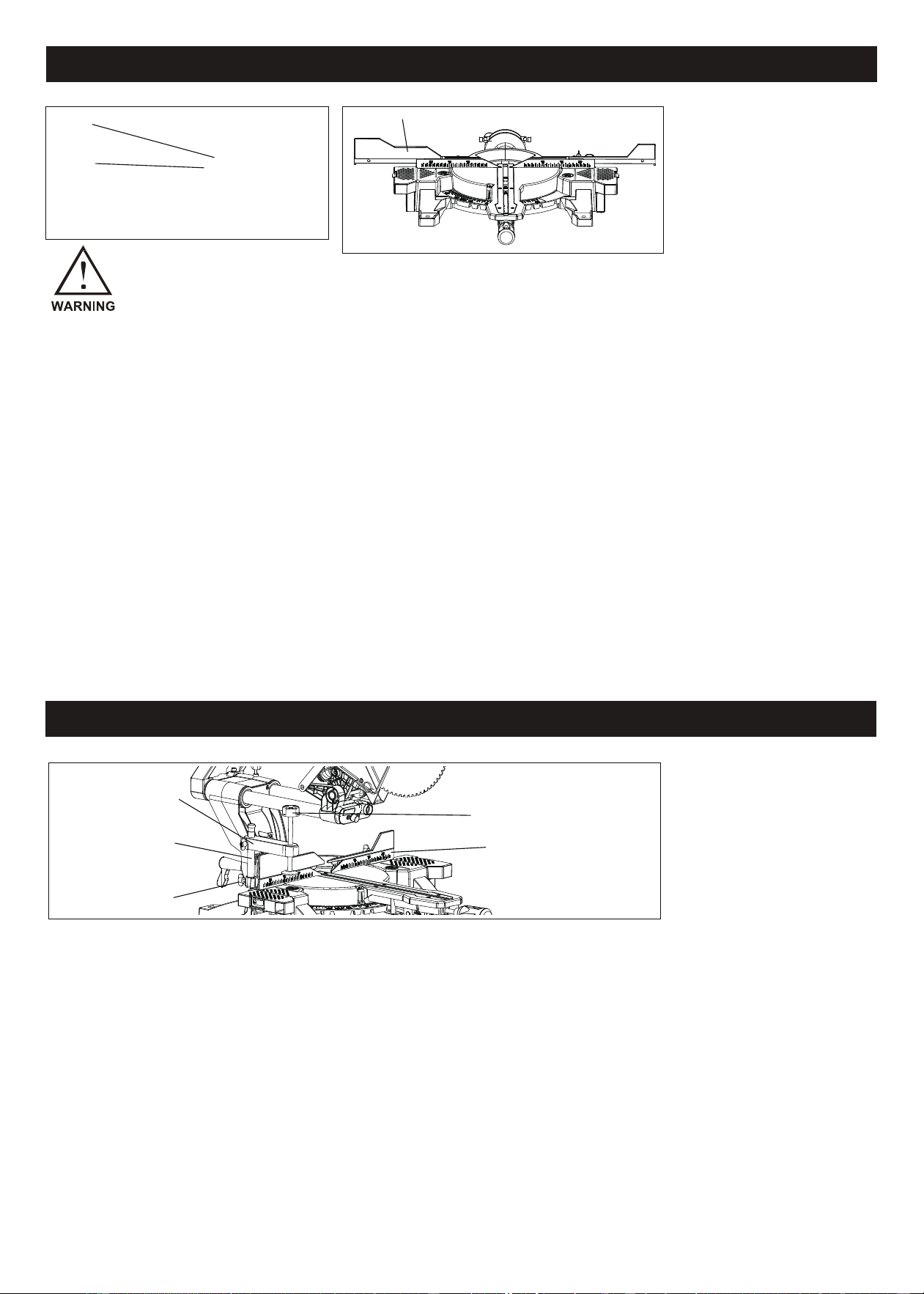
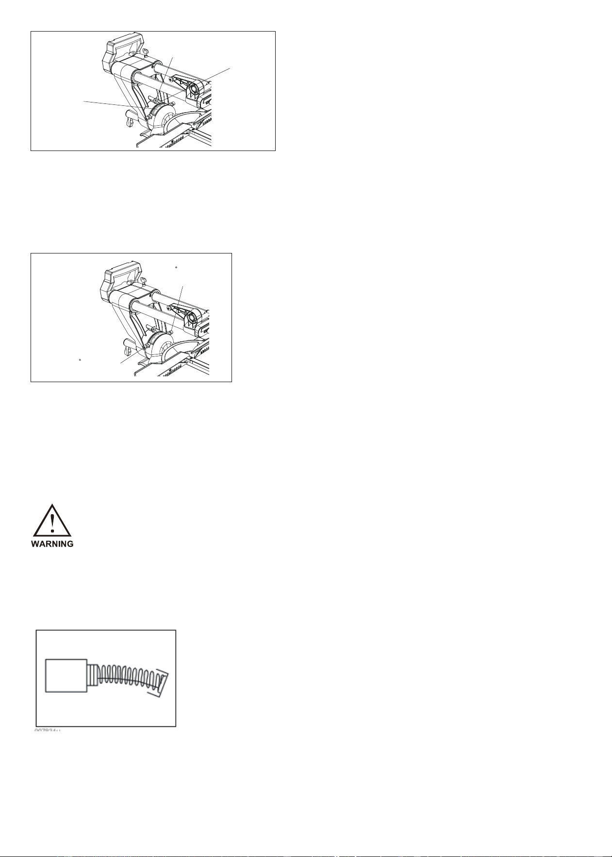
2. Bevel Angle:
(1) 0° Bevel Angle
Push the carriage towards the guide fence and secure it by tightening the locking screw. Fully lower the handle and
lock it in place using the stopper pin. Loosen the lever at the rear of the tool.
Turn the hex bolt on the right side of the arm counterclockwise for two or three revolutions to tilt the blade to the right.
Precisely align the side of the blade with the top surface of the turn base using a triangular rule, try-square, etc.
Rotate the hex bolt on the right side of the arm clockwise and securely tighten the lever.
Ensure that the pointer on the arm points to 0° on the bevel scale of the arm holder. If it does not align with 0°, loosen
the screw securing the pointer and adjust it until it points to 0°.
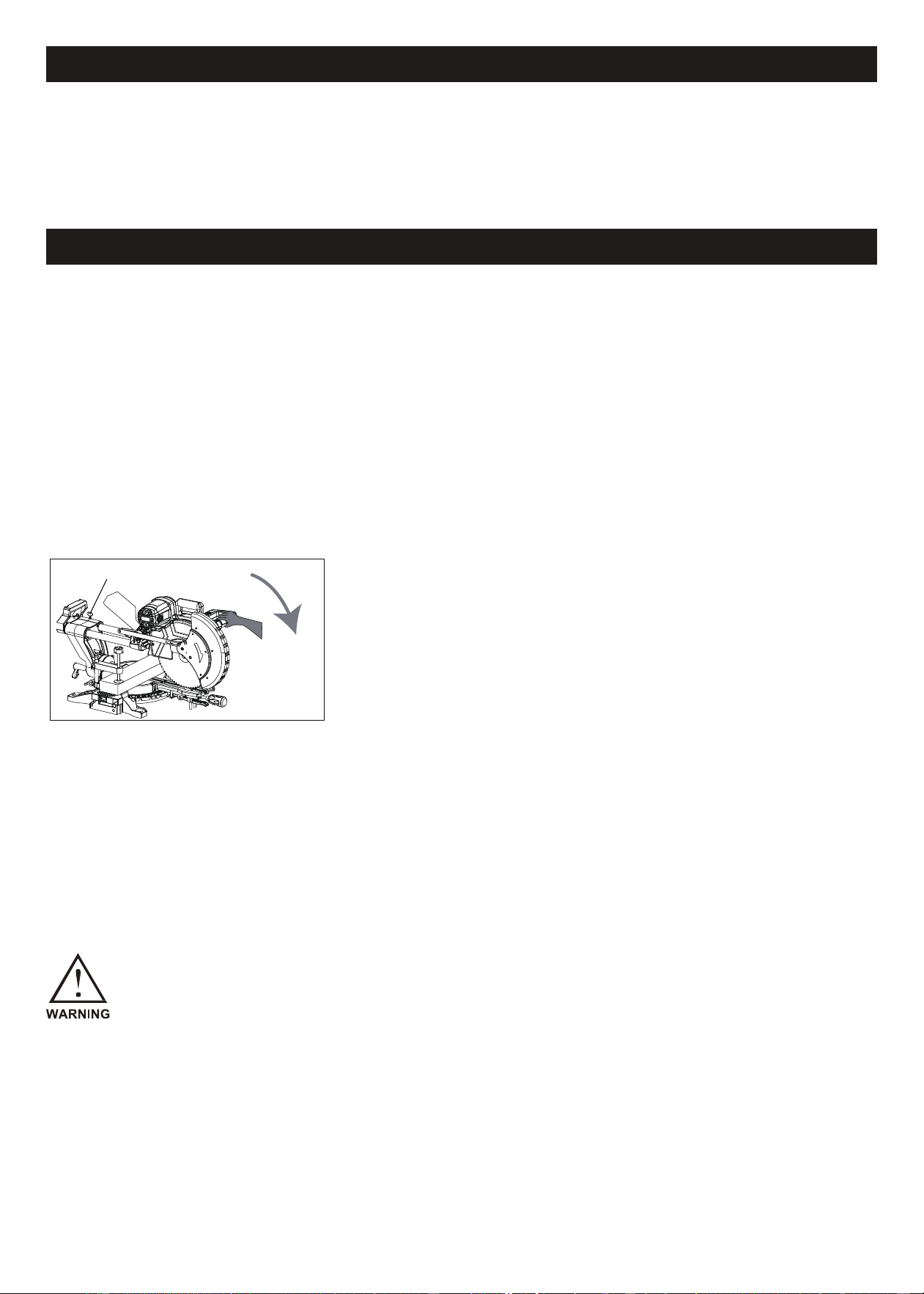
(2) 45° Bevel Angle
For a left miter cut at 45°: Confirm the angle is at 0°, unlock the machine head by turning the angle lock button coun-
terclockwise on the back of the boom, tilt the machine head to the left, and then lock it by turning the angle lock button
clockwise.
For a right miter cut at 45°: Turn the angle lock button counterclockwise to unlock the machine head, pull out the
locking shaft, tilt the machine head to the right, and then lock it by turning the angle lock button clockwise.
Regularly inspect and replace carbon brushes when they wear down to 3 mm in length. Keep the carbon brushes
clean and free to move in the holders. Replace both carbon brushes simultaneously, using identical ones. Use a
screwdriver to remove the brush holder caps, replace the worn carbon brushes with new ones, and secure the brush
holder caps.
- 17 -
Blade Maintenance:
Regularly check and ensure the blade is sharp and clean for optimal and safe performance.
Attempting a cut with a dull and/or dirty blade may result in kickback and serious personal injury.
NOTICE:
Never use gasoline, benzine, thinner, alcohol, or similar substances, as they may cause discoloration, deformation,
or cracks.
Adjusting the Cutting Angle:
While this tool undergoes precise adjustment and alignment at the factory, rough handling during transportation may
impact its alignment. If you observe any misalignment issues with your tool, please follow the steps below for proper
realignment:
1. Miter Angle:
Push the carriage toward the guide fence and tighten the locking screw to secure it.
Loosen the grip securing the turn base. Set the pointer to 0° on the miter scale by turning the turn base slightly clock-
wise and counterclockwise.
Loosen the hex socket bolts securing the guide fence.
Lower the handle fully and lock it in the lowered position using the stopper pin.
Square the side of the blade with the face of the guide fence using a triangular rule or try-square.
Securely tighten the hex socket bolts on the guide fence starting from the right side.
Ensure that the pointer aligns with 0° on the miter scale. If it doesn't, loosen the screw securing the pointer and make
the necessary adjustments to align it with 0°.
2. Bevel Angle:
(1) 0° Bevel Angle
Push the carriage towards the guide fence and secure it by tightening the locking screw. Fully lower the handle and
lock it in place using the stopper pin. Loosen the lever at the rear of the tool.
Turn the hex bolt on the right side of the arm counterclockwise for two or three revolutions to tilt the blade to the right.
Precisely align the side of the blade with the top surface of the turn base using a triangular rule, try-square, etc.
Rotate the hex bolt on the right side of the arm clockwise and securely tighten the lever.
screw
pointer
miter scale
lever
arm
Before initiating bevel angle cutting, check if the pointer aligns with
0°. If it deviates to the left, adjust the Right 45° bevel angle adjusting
bolt; if it deviates to the right, adjust the Left 45° bevel angle adjust-
ing bolt.
left 45 bevel angle
adjusting bolt
pointer
Right 45 bevel angle
adjusting bolt
top surface of turn table
Ensure that the pointer on the arm points to 0° on the bevel scale of the arm holder. If it does not align with 0°, loosen
the screw securing the pointer and adjust it until it points to 0°.
(2) 45° Bevel Angle
For a left miter cut at 45°: Confirm the angle is at 0°, unlock the machine head by turning the angle lock button coun-
terclockwise on the back of the boom, tilt the machine head to the left, and then lock it by turning the angle lock button
clockwise.
For a right miter cut at 45°: Turn the angle lock button counterclockwise to unlock the machine head, pull out the
locking shaft, tilt the machine head to the right, and then lock it by turning the angle lock button clockwise.
Regularly inspect and replace carbon brushes when they wear down to 3 mm in length. Keep the carbon brushes
clean and free to move in the holders. Replace both carbon brushes simultaneously, using identical ones. Use a
screwdriver to remove the brush holder caps, replace the worn carbon brushes with new ones, and secure the brush
holder caps.
- 18 -
WARNING:
To tilt to the right, first pull out the lock pin and then tilt to the right. If you don't need to tilt to the right, push
the locking shaft back to its original position.
Blade Maintenance:
Regularly check and ensure the blade is sharp and clean for optimal and safe performance.
Attempting a cut with a dull and/or dirty blade may result in kickback and serious personal injury.
NOTICE:
Never use gasoline, benzine, thinner, alcohol, or similar substances, as they may cause discoloration, deformation,
or cracks.
Adjusting the Cutting Angle:
While this tool undergoes precise adjustment and alignment at the factory, rough handling during transportation may
impact its alignment. If you observe any misalignment issues with your tool, please follow the steps below for proper
realignment:
1. Miter Angle:
Push the carriage toward the guide fence and tighten the locking screw to secure it.
Loosen the grip securing the turn base. Set the pointer to 0° on the miter scale by turning the turn base slightly clock-
wise and counterclockwise.
Loosen the hex socket bolts securing the guide fence.
Lower the handle fully and lock it in the lowered position using the stopper pin.
Square the side of the blade with the face of the guide fence using a triangular rule or try-square.
Securely tighten the hex socket bolts on the guide fence starting from the right side.
Ensure that the pointer aligns with 0° on the miter scale. If it doesn't, loosen the screw securing the pointer and make
the necessary adjustments to align it with 0°.
2. Bevel Angle:
(1) 0° Bevel Angle
Push the carriage towards the guide fence and secure it by tightening the locking screw. Fully lower the handle and
lock it in place using the stopper pin. Loosen the lever at the rear of the tool.
Turn the hex bolt on the right side of the arm counterclockwise for two or three revolutions to tilt the blade to the right.
Precisely align the side of the blade with the top surface of the turn base using a triangular rule, try-square, etc.
Rotate the hex bolt on the right side of the arm clockwise and securely tighten the lever.
screw
pointer
bevel scale
Ensure that the pointer on the arm points to 0° on the bevel scale of the arm holder. If it does not align with 0°, loosen
the screw securing the pointer and adjust it until it points to 0°.
(2) 45° Bevel Angle
For a left miter cut at 45°: Confirm the angle is at 0°, unlock the machine head by turning the angle lock button coun-
terclockwise on the back of the boom, tilt the machine head to the left, and then lock it by turning the angle lock button
clockwise.
For a right miter cut at 45°: Turn the angle lock button counterclockwise to unlock the machine head, pull out the
locking shaft, tilt the machine head to the right, and then lock it by turning the angle lock button clockwise.
Regularly inspect and replace carbon brushes when they wear down to 3 mm in length. Keep the carbon brushes
clean and free to move in the holders. Replace both carbon brushes simultaneously, using identical ones. Use a
screwdriver to remove the brush holder caps, replace the worn carbon brushes with new ones, and secure the brush
holder caps.
left 45 bevel angle
adjusting bolt
Right 45 bevel angle
adjusting bolt
- 19 -

After Use
Brush holder cap
Screwdriver
After Replacing Brushes
Plug in the tool and run it with no load for about 10 minutes to break in the new brushes. Check the tool while running,
and observe electric brake operation when releasing the switch trigger.
After use, clean off chips and dust adhering to the tool with a cloth. Follow the directions in the "Blade guard" section
to keep the blade guard clean. Apply machine oil to the sliding portions to prevent rust. When storing the tool, pull the
carriage fully towards you.
- 20 -

5002770
www.dovaman.com
Shenzhen Yangtuo Electronic Commerce Co., Ltd
No.51, Pingxin North Road, Shangmugu Community,
Pinghu Street,Longgang District, Shenzhen, China 518000