SPECIFICATION
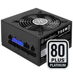
SilverStone Strider ST75F
Switching Power Supply
With Active PFC
PS/2 Modular 750W
1. AC INPUT
1.1 AC input requirements
The input voltage, current, and frequency requirements for continuous operation are stated
below.
Table 1 AC Input Line Requirements
Parameter Min. Nom. Max. Unit
Vin( Full range ) 103 115---240 264 VACrms
Vin Frequency 47 60----50 63 Hz
Iin
10-----5 5 Arms
Power factor correction (PF)>0.95 at full load
1.2 Inrush current regulation
50 A @ 115Vrms
100 A @ 230Vrms (at 25°C ambient cold start)
2. DC OUTPUT
2.1 DC voltage regulation
Parameter Range Min Nom. Max Unit
+3.3V
+/-5%
+3.14 +3.3 +3.47 Volts
+5V
+/-5%
+4.75 +5 +5.25 Volts
+12V1
+/-5%
+11.4 +12 +12.6 Volts
+12V2
+/-5%
+11.4 +12 +12.6 Volts
+12V3
+/-5%
+11.4 +12 +12.6 Volts
+12V4
+/-5%
+11.4 +12 +12.6 Volts
-12V
+/-10%
-10.8 -12 -13.2 Volts
+5VSB
+/-5%
+4.75 +5 +5.25 Volts
2.2 Load ranges
2.2.1 : (750 Watts Load Ratings)
Parameter Min Nom. Max Unit
+3.3V
+5V
+12V1
+12V2
+12V3
+12V4
-12V
+5VSB
1.5
5.0
1.5
1.5
1.5
1.5
0
0.1
-
-
-
-
-
-
-
-
24
30
18
18
18
18
0.5
3.0
Amps
Amps
Amps
Amps
Amps
Amps
Amps
Amps
Notes:
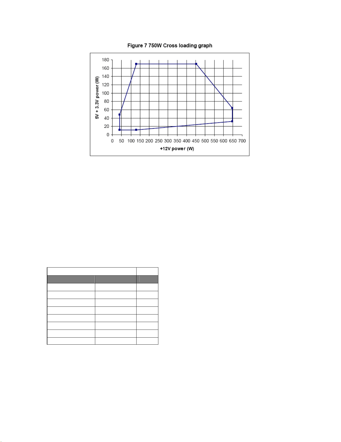
(1) The maximum continuous total DC outputs power shall not exceed 750W.
(2) The maximum continuous load on +5V and +3.3V outputs shall not exceed 170W.
(3) The maximum combined current for the +12V outputs shall be 54A/56A peak.
(4) The 5V standby output shall remain on while the AC input power connected, whether DC outputs are disabled (Off)
or enabled (On) by the remote on control signal, but when the 5V Standby output remained on with the AC input power
turn off, the remote on control will be disabled.
2.3 Output Ripple
2.3.1 Ripple regulation
Parameter Ripple&Noise Unit
+3.3V 100 mVp-p
+5V 100 mVp-p
+12V1 150 mVp-p
+12V2 150 mVp-p
+12V3 150 mVp-p
+12V4 150 mVp-p
-12V 150 mVp-p
+5VSB 100 mVp-p
2.3.2 Definition
The ripple voltage of the outputs shall be measured at the pins of the output connector
when terminated in the load impedance specified in figure 1. Ripple and noise are measured
at the connectors with a 0.1uF ceramic capacitor and a 10uF electrolytic capacitor to simulate
system loading. Ripple shall be measured under any condition of line voltage, output load, line
frequency, operation temperature.
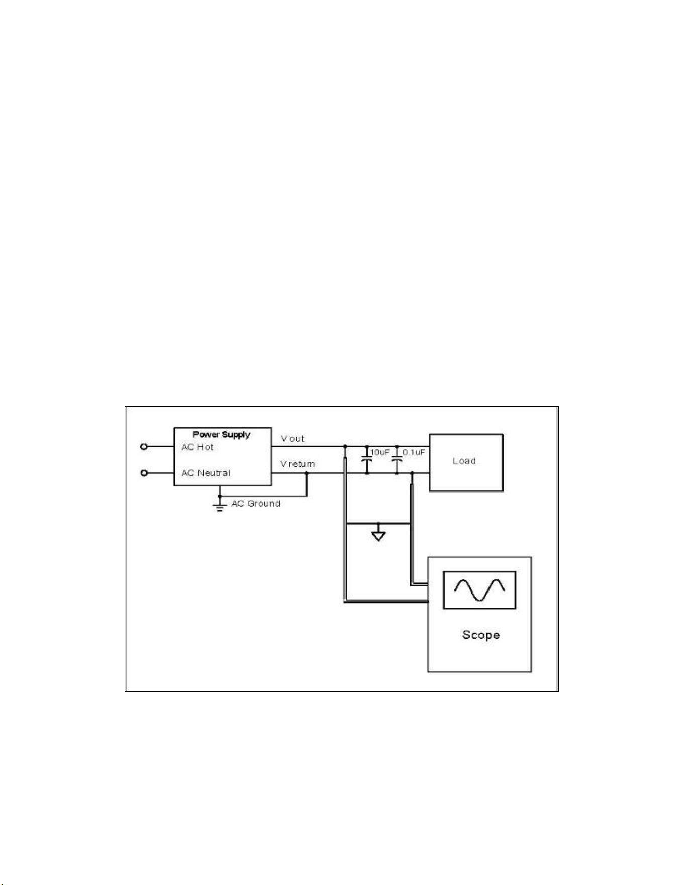
2.3.3 Ripple voltage test circuit
Figure 1. Ripple voltage test circuit
2.4 Overshoot
Any overshoot at turn on or turn off shall be less 10% of the nominal voltage
value, all outputs shall be within the regulation limit of section 2.0 before issuing the
power good signal of section 5.0.
2.5 Efficiency
80% typical and 83.70% maximum
2.6 Remote ON/OFF control
When the logic level "PS-ON" is low, the DC outputs are to be enabled.
When the logic level is high or open collector, the DC outputs are to be disabled.
3.0 PROTECTION
3.1 Over current protect
The power supply shall have current limit to prevent the +3.3V, +5V, and +12V1, +12V2,
+12V3 outputs from exceeding the values shown in the following Table. If the current limits
are exceeded the power supply shall shutdown and latch off.
Dual +12V for processor (750W)
Voltage Over Current Limit (Iout limit)
+12V1 19.8A minimum; 27A maximum
+12V2 19.8A minimum; 27A maximum
+12V3 19.8A minimum; 27A maximum
+12V4 19.8A minimum; 27A maximum
+5V 33A minimum; 45A maximum
+3.3V 26A minimum; 36A maximum
3.2 Under voltage protection.
In an under voltage fault occurs, the supply will latch all DC outputs into a shutdown state
when +5V & +3.3V outputs under 85% of its maximum value.
3.3 Over voltage protection
The over voltage sense circuitry and reference shall reside in packages that are separate
and distinct from the regulator control circuitry and reference. No single point fault shall
be able to cause a sustained over voltage condition on any or all outputs. The supply shall
provide latch-mode over voltage protection as defined in Table.
output Minimum Nominal Maximum Unit
+12 VDC 13.4 15.0 15.6 Volts
+5 VDC 5.74 6.3 7.0 Volts
+3.3 VDC 3.76 4.2 4.3 Volts
3.4Short circuit
An output short circuit is defined as any output impedance of less than 0.1 ohms. The power
supply shall shut down and latch off for shorting the +3.3 VDC, +5 VDC,or+12 VDC rails to
return or any other rail. Shorts between main output rails and +5VSB shall not cause any
damage to the power supply. The power supply shall either shut down and latch off or fold back
for shorting the negative rails.+5VSB must be capable of being shorted indefinitely, but when
the short is removed, the power supply shall recover automatically or by cycling PS_ON#. The
power supply shall be capable of withstanding a continuous short-circuit to the output without
damage or overstress to the unit
3.5 No load operation
No damage or hazardous condition should occur with all the DC output connectors
disconnected from the load. The power supply may latch into the shutdown state.
4. TIMING
4.1 Signal timing drawing
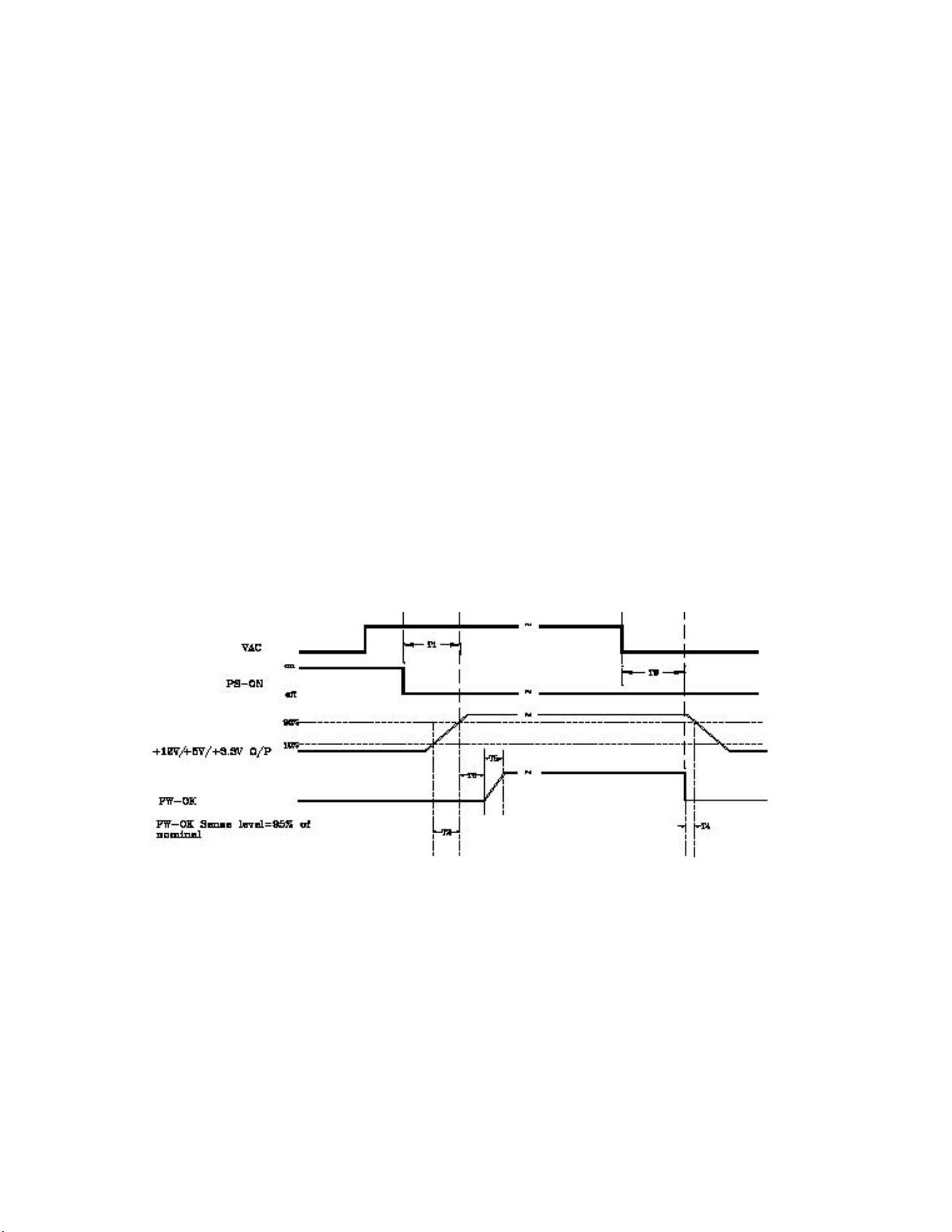
Figure 2. is a reference for signal timing for main power connector signals and rails.
Figure 2. PS-OK Timing Sequence
(1)T2: Rise time (0.1ms~70ms)
(2)T3: Power good signal turn on delay time (100ms~1000ms)
(3)T4: Power good signal turn off delay time (1ms min)
(4)T5: Rise time (10ms max)
(5)T6: Hold up time (17ms min)
4.2 Hold up time
When the power loss its input power, it shall maintain 17ms in regulation limit at normal input
voltage (AC:115V/60Hz or 230V/50Hz)
5. ENVIRONMENT
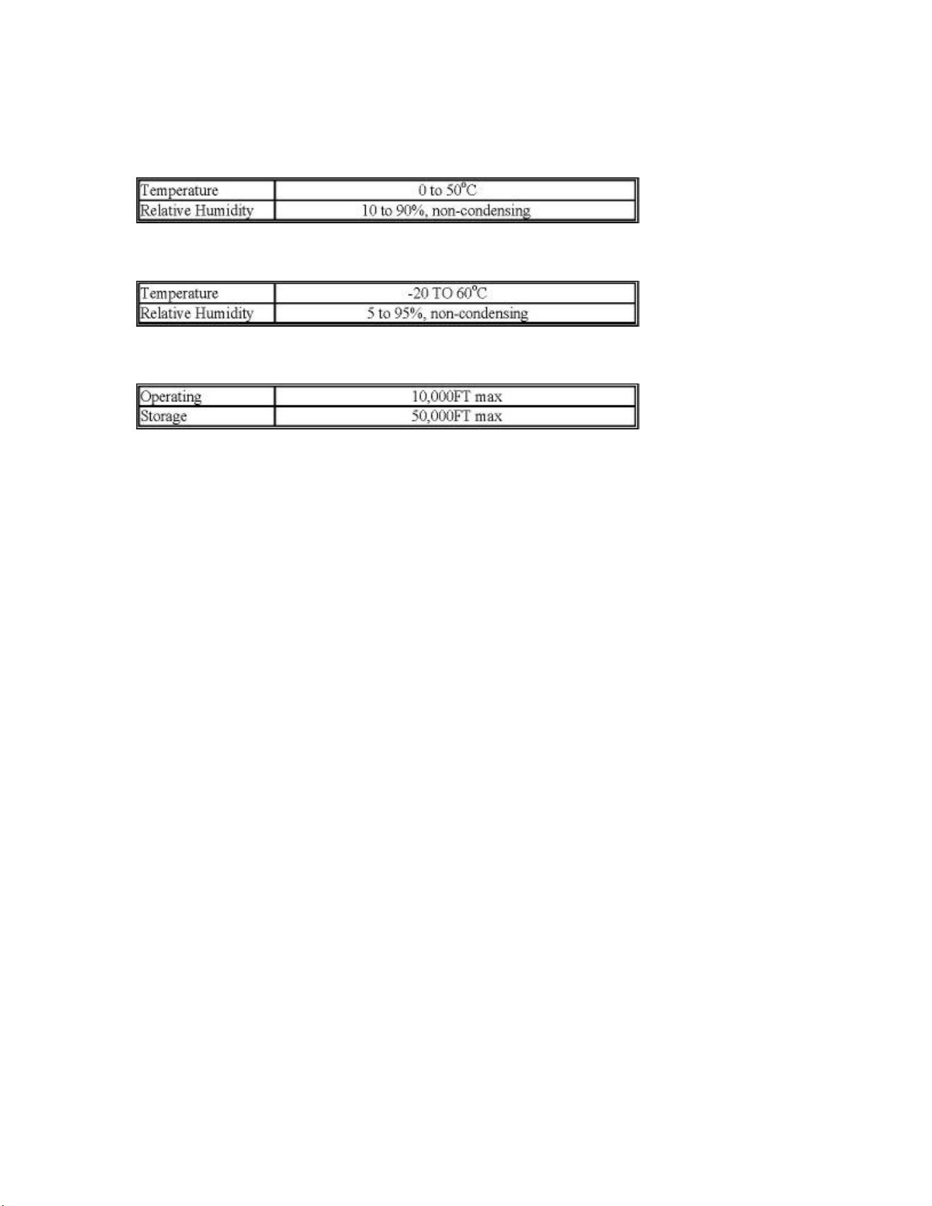
5.1 Operation
5.2 Shipping and Storage
5.3 Altitude
6. SAFETY
6.1 Underwriters Laboratory (UL) recognition.
The power supply designed to meet UL 1950.
6.6 The power supply must bear the German Bauart Mark from TUV.
7. ELECTROMAGNETIC COMPATIBILITY (EMC)
7.1 IEC 1000-4-2 ESD LEVEL X20KV4.
7.2 IEC 1000-4-3 radiated electrical field requirement.
7.3 IEC 1000-4-4 BURST
7.4 IEC 1000-4-5 surge Voltages
7.5 EN61000-3-2 harmonic current emissions.
If applicable to sales in Japan or Europe, the power supply shall meet the requirements of
EN 61000-3-2 class D and the guidelines for the suppression of harmonics in appliances and
general use equipment class D for harmonic line current content at full-rated power.
7.6 EN55024 class B radio interference (CISPR 22)
7.7 FCC part 15, subpart J class B 115VAC operation.
8. MTBF
8.1 MTBF (mean time between failures) calculation
The demonstrated MTBF shall be 100,000 hours of continuous operation at 25
°C, full load, 80%
confidence limit and nominal line. The MTBF of the power supply be calculated in accordance
with MIL-HDBK-217F. The DC FAN is not included.
9. MECHANICAL REQUIREMENTS
9.1 Physical dimension
150 x 86 x 180 mm (W x H x D)
9.2 Net weight
3 kg (without cables)
9.3 Pin definition
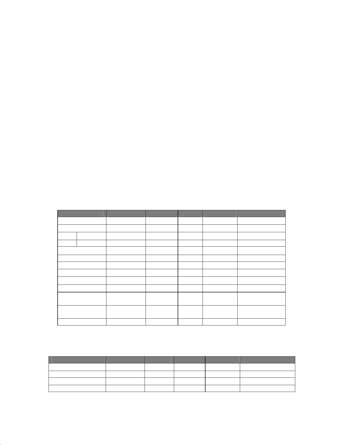
M/B 24PIN connector
16AWG wire Signal Pin Pin Signal 16AWG wire
Orange +3.3V 13 1 +3.3V Orange
Orange(22AWG) +3.3Vsense 13
Blue (18AWG) -12VDC 14 2 +3.3V Orange
Black COM 15 3 COM Black
Green(20AWG) PS-ON 16 4 +5VDC Red
Black COM 17 5 COM Black
Black COM 18 6 +5VDC Red
Black COM 19 7 COM Black
N/C N/C 20 8 PWRGOOD Grey (20AWG)
Red +5VDC 21 9 +5Vsb Purple(18AWG)
Red +5VDC 22 10 +12V3 Yellow/Blue
stripe
Red +5VDC 23 11 +12V3 Yellow/Blue
stripe
Black COM 24 12 +3.3V Orange
4PIN peripheral connector (HDD) 4PIN floppy connector (FDD)
18 AWG wire Signal Pin Pin Signal 22AWG wire
Yellow/Green stripe +12V4 1 1 +5VDC Red
Black COM 2 2 COM Black
Black COM 3 3 COM Black
Red +5VDC 4 4 +12V4 Yellow/Green stripe
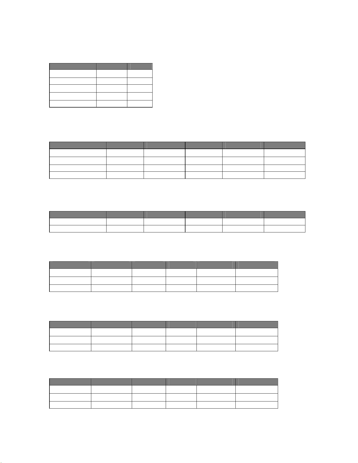
SATA connector
18AWG wire Signal Pin
Orange
+3.3V 5
Black
GND 4
Red
+5V 3
Black
GND 2
Yellow
+12V4 1
EPS 12V 8PIN Connector
18AWG wire Signal Pin Pin Signal 18AWG wire
Yellow
+12V2
5 1 COM Black
Yellow +12V2 6 2 COM Black
Yellow/Black +12V1 7 3 COM Black
Yellow/Black +12V1 8 4 COM Black
ATX 12V 4PIN Connector
18AWG wire Signal Pin Pin Signal 18AWG wire
Yellow/Black stripe +12V1 3 1 COM Black
Yellow/Black stripe +12V1 4 2 COM Black
EPS 12V 6PIN Connector
18AWG wire Signal Pin Pin Signal 18AWG wire
Orange +3.3V 1 4 GND Black
Orange +3.3V 2 5 GND Black
Yellow +12V2 3 6 Yellow +12V2
6PIN PCI Express Connector 1 & 2
18AWG wire Signal Pin Pin Signal 18AWG wire
Yellow/Blue +12V3 1 4 GND Black
Yellow/Blue +12V3 2 5 GND sense Black
Yellow/Blue +12V3 3 6 GND Black
6PIN PCI Express Connector 3 & 4
18AWG wire Signal Pin Pin Signal 18AWG wire
Yellow/Green +12V4 1 4 GND Black
Yellow/Green +12V4 2 5 GND sense Black
Yellow/Green +12V4 3 6 GND Black