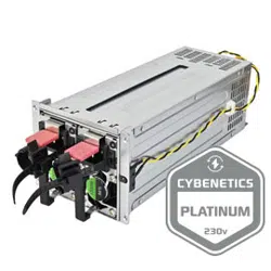

ST55F-PB
ST65F-PB
ST75F-PB
STRIDER PLUS BRONZE SERIES
High efficiency with 80 PLUS Bronze certification
24/7 continuous power output with 40℃ operating temperature
100% modular cables with flexible flat arrays
Class-leading single +12V rail
Strict ±3% voltage regulation and low ripple & noise
Silent running 120mm fan with 18dBA
PCIe 8/6pin connectors support
Power supplies with excellent combination
of features, efficiency, and durability
o

SPECIFICATION
STRIDER PLUS BRONZE SERIES
SST-ST75F-PB
SST-ST65F-PB
SST-ST55F-PB
ATX12V / EPS 12V Switching Power Supply
With Active PFC
80 PLUS Bronze
PS/2
01
1.1Scope
This specification defines the performance characteristics of a single phase 550W,650W, 750W,
5 output power supply. This specification also defines worldwide safety and electromagnetic
compatibility requirements for the power supply which is intended for use in computer products.
1. General
2.1 Input Voltage
Nominal Voltage Voltage Variation Range
--------------------- --------------------------------
115 - 240 Vrms 103 - 264 Vrms
2.2 Input Frequency
Nominal Frequency Frequency Variation Range
------------------------ -------------------------------------
50 - 60 Hz 47 - 63 Hz
2.3 Max. Input AC Current
Max. Input Current Measuring Range
-------------------------- -------------------------
10A 103 - 264 Vrms
* The power supply must operate at above frequency with 103-264 VACrms input voltage range.
2. Input Characteristics
5VSB
Load Target
Efficiency target
(both 110V and 230V input)
Remark
45mA 45% ErP* Lot 6 2013
90mA 45% ErP* Lot 6 2010
0.55A 75%
ASM for CEC* &
ErP* Lot 3 2014
1.5A 75%
ASM for CEC* & ErP
Lot 3 2014
2.5A 75% Recommend
02
2.4 Inrush Current
The power supply must meet inrush requirements for any rated AC voltage, during turn on at any phase
of AC voltage, during a single cycle AC dropout condition, during repetitive ON/OFF cycling of AC, and
over the specified temperature range. The peak inrush current shall be less than the ratings of its critical
components (including input fuse, bulk rectifiers, and surge limiting device).
Power supply typical efficiency is 82% under full Load at nominal input voltage of 115VAC
2.5 Efficiency
2.6 ErP requirement
3.1 Normal Operation Output
ST55F-PB
ST65F-PB
3. Output characteristics
o
Maximum continuous total DC output power should not exceed 550W.
Maximum continuous combined load on +3.3VDC and +5VDC outputs shall not exceed 100W.
Maximum combined load on +12V outputs shall not exceed 510W.
Output
Voltage
Load
Min.
Range
Max.
Regulation
Ripple & Noise
P-P Max.
1. +5V 0.2A 18A
±3%
50mV
2. +12V 0.1A 42.5A
±3%
80mV
3. –12V 0.0A 0.3A
±10%
100mV
4. +5Vs 0.0A 2.5A
±5%
50mV
5. +3.3V 0.0A 18A
±3%
50mV
Output
Voltage
Load
Min.
Range
Max.
Regulation
Ripple & Noise
P-P Max.
1. +5V 0.2A 18A
±3%
50mV
2. +12V 0.1A 50.8A
±3%
80mV
3. –12V 0.0A 0.3A
±10%
100mV
4. +5Vs 0.0A 2.5A
±5%
50mV
5. +3.3V 0.0A 18A
±3%
50mV
5VSB
Load Target
Remark
Efficiency target
(both 110V and 230V input)
03
ST75F-PB
3.3 Regulation
3.2 Remote On/Off Controlled mode
The cross regulation defined as follows, the output regulation should be within the specified range.
ST55F-PB
ST65F-PB
ST75F-PB
3.4 Rise Time
DC output rise time is less than 20 mS at nominal line and full load.
Maximum continuous total DC output power should not exceed 650W.
Maximum continuous combined load on +3.3VDC and +5VDC outputs shall not exceed 100W.
Maximum combined load on +12V outputs shall not exceed 610W.
Maximum continuous total DC output power should not exceed 750W.
Maximum continuous combined load on +3.3VDC and +5VDC outputs shall not exceed 100W.
Maximum combined load on +12V outputs shall not exceed 710W.
Noise test should be measured with 20 MHz bandwidth frequency oscilloscope. The output terminal
shall add a tantalum capacitor of 10uF in parallel with a ceramic capacitor of 0.1uF.
The PSON# signal is required to remotely turn on/off the power supply, PSON# is an active low signal
that turns on the output power rails. When this is not pulled low by the system, or left open, the outputs
(except the +5VSB) turn off. This signal is pulled to a standby voltage by a pull-up resistor internal to
the power supply.
TTL level "H" 2.0 V - 5.25 V "L" 0.0 V - 1.0 V
NOTE:
Output
Voltage
Load
Min.
Range
Max.
Regulation
Ripple & Noise
P-P Max.
1. +5V 0.2A 18A
±3%
50mV
2. +12V 0.1A 59.1A
±3%
80mV
3. –12V 0.0A 0.3A
±10%
100mV
4. +5Vs 0.0A 2.5A
±5%
50mV
5. +3.3V 0.0A 18A
±3%
50mV
Load +5V +3.3V +12V -12V +5Vsb
Light Load.
2.19 A 2.19 A 10.74 A 0.05 A 0.45A
Typical Load
5.47 A 5.47 A 26.86 A 0.14 A 1.13 A
Full Load
10.94 A 10.94 A
53.72 A
0.27 A 2.27 A
Load +5V +3.3V +12V -12V +5Vsb
Light Load.
2.16 A 2.16 A 9.10 A 0.05 A 0.45A
Typical Load
5.39 A 5.39A 22.75A 0.13 A 1.12 A
Full Load
10.79A 10.79 A
45.51
A
0.27 A 2.24A
Load +5V +3.3V +12V -12V +5Vsb
Light Load.
2.12 A 2.12 A 7.47 A 0.05 A 0.44A
Typical Load
5.29 A 5.29A 18.67A 0.13 A 1.10 A
Full Load
10.58A 10.58 A
37.33A
0.26 A 2.20A
04
3.5 Hold-up Time
DC +5V, +3.3V ,+12V output maintains at least 16mS after power off which hold within 75% loads
under 230V/50Hz condition.
A default 3.3V sense line should be implemented pin 13 of the connector.
5VSB is required for the implementation of PS-ON described above. 5VSB is a standby voltage that
may be used to power circuits that require power input during the powered-down state of all power
rails. The 5 VSB pin should deliver 5V ± 5% at a minimum of 3.0 A for PC board circuits to operate.
Conversely, PC board should draw no more than 3.0A maximum form this pin. This power maybe
used to operate circuits such as soft power control.
PG-OK is a power good signal and should be asserted high by power supply to indicate that the +5 VDC
and +3.3 VDC outputs are above the under-voltage thresholds of the power supply. When this signal is
asserted high, there should be sufficient mains energy stored by the converter to guarantee continuous
power operation within specification. Conversely, when either the +5VDC or the +3.3VDC output voltage
falls below the under-voltage threshold, or when mains power has been removed for a time sufficiently
long so that power supply operation is no longer guaranteed, PG-OK should be deserted to a low state.
See Figure 1 for a representation of the timing characteristics of the PG-OK, PS-ON, and germane
power rail signals.
3.6 5VSB
3.7 PG-OK
3.8 3.3V Sense
The power supply should be able to power up and operate normally with the following capacitances
simultaneously present on the DC outputs.
3.9 Capacitive Load
In primary circuit of the power supply , a protected fuse is inserted. Only internal fault of the
power supply will cause the fuse blown. Any overload or short circuit at DC output will keep from fuse
brown or fire hazard.
4.1 Input Protection
4.2.1 Under voltage protection
The +5V/+12V/+3.3V DC output are protected against the under voltage condition . range value
can't be exceed 3.3~3.7V at 5V terminal and 8.5~9.5V at 12V, 2.0~2.4V at 3.3V.
4.2.2 Over Voltage Protection
The +12V/ DC output are protected against the over voltage condition . Maximum value can't be
over 15.5V at 12V.
4.2.3 Over Power Protection
The power supply can be used electronic circuit to limit the output current against exceeding
10%-60% of surge output power or protected against excessive power delivery since short circuit
of any output or over total power at high line.
4.2 Output Protection
4. Protection
o
Output Capacitive load (uF)
+5V 10,000
+12V 10,000
+3.3V 10,000
-12V 330
+5VS 10,000
05
5.1 No Load Start
5. Start Stability
When power is applied to ST55F-PB,ST65F-PB and ST75F-PB with no load connected or under
minimum load connected, neither damage to power supply nor hazards to users will occur.
The power supply can operate normally at any altitude between 0 to 10000 feet.
6.1Temperature and Humidity
6.2 Altitude
Sweep and resonance search for each of X,Y,Z, axis at the sweep.
RATE of 1/OCTAVE/Min.
6.3 Vibration and Shock
6. Environments
CE,FCC
7. Conducted EMI
8.1 Safety Requirement
cTUVus, CB, TUV,CE,FCC, RCM,CCC
8. Product Safety
5.2 Cold Start
The power supply shall operate properly when first applied at normal input voltage and or so maximum
load after 4 hours storage in 0℃ environment.
4.2.4 Short Circuit Protection
Short circuit placed on +5V,+12V,+3.3V,-12V will latch off. +5VSB will auto-recovery.
4.2.5 Over-Current Protection
Current protection should be designed to limit the current to operate within safe operating
conditions. Over current protection schemes where only the voltage output that experiences
the over current event is shut off may be adequate to maintain safe operation of the power supply
and the system; however, damage to the motherboard or other system components may occur.
The recommended over current protection scheme is for the power supply to latch into the
shutdown state.
4.2.6 Over-Temperature Protection
This power supply includes an over-temperature protection sensor, which can
trip and shut down the power supply at 110℃
6.1.1 Operating
Temperature 0 to 40 ℃
Relative Humidity 20 to 90 %
6.1.2 Storage
Temperature -40 to 70 ℃
Relative Humidity 20 to 95 % noncondensing
Frequency Duration Amplitude
5-55-10 Hz 30 minutes 0.35 mm
06
8.2 Leakage Current
The AC leakage current is less than 3.5mA when the power supply connect to 264Vac/50Hz.
The insulation resistance should be not less than 30M ohm after applying of 500VDC for 1 minute.
The power supply shall withstand for 1 minute without breakdown the application of a 60Hz 1500V AC
voltage applied between both input line and chassis (20mA DC cut-off current). Main transformer shall
similarly withstand 3000Vac applied between both primary and secondary windings for a minimum of
one minute.
8.3 Insulation Resistance
8.4 Dielectric Voltage Withstand
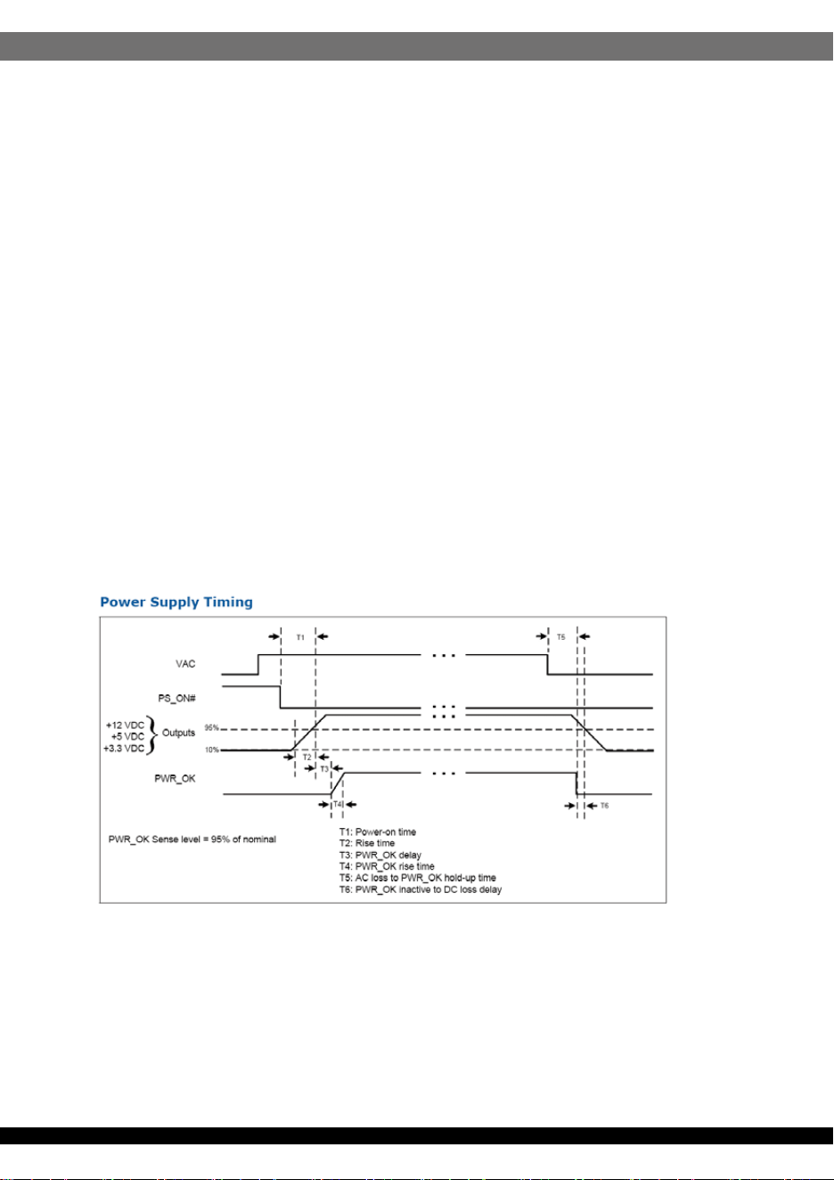
A TTL compatible signal for the purpose of initiating an orderly start-up procedure
under normal input operating conditions. During power up, this signal is asserted
( low ) until +5V is under regulation and AC reaches min. line specification range.
After all voltage are going appropriate level, the system may have a turn on delay
of 100mS, but no greater than 500mS. During power off the signal should go to low
level before +5V is out of regulation. The low level is 0 to 0.8V and high level is
4.75 to 5.25V. The " Power Good "signal can drive up to 6 standard TTL loads.
Time Diagram Figure 1
* T1 : Turn on time ( 500mS Max.)
* T2 : Rise time ( ≦ 20mS Max.)
* T3 : Power good turn on delay time ( 100 < T3 < 500 mS )
* T4 : Switch on time (10mS Max.)
* T5 : Power hold-on time ( 16 mS Min )
* T6 : Power good turn off delay time ( 1.0 mS Min.)
* Power on-off cycle :
When the power supply is turned off for a minimum of 2.0 sec. and turn on again,
the power good signal will be asserted.
9. Power Good Signal
o
07
The MTBF of the power should be 100,000 hours min.
The product shall meet requirement for EN61000-3-2 & EN61000-3-3 :1995
standard of class D, test at 230Vac 50Hz.
10. MTBF
11.1 Input Voltage
11. Burn-In
12. Harmonics
The power supply with active power factor correction, and meet the EN61000-3-2
standards, The power factor is greater than 0.9 at 230V/50Hz, Max. load.
13. Power Factor
14. Mechanical Specification
Applying 220Vac .
14.1 Dimension
150mmX86mmX140mm
11.2Test Condition
Applying 80% loads for the power supply in 40 (+/-5) oC chamber for 4 hours.
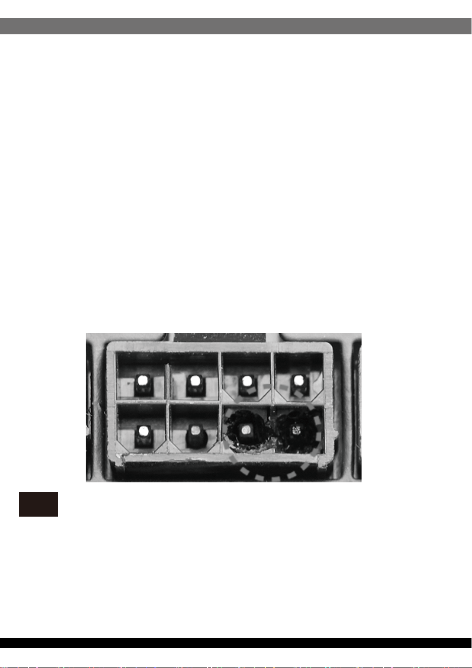
15. Power supply connector overuse definition
Power supply connector overuse definition
EN
A single PCIe 8pin cable and connector’s maximum current rating is 12.5A, which is 150W (+12V x 12.5A). So SilverStone’s warranty will not
cover damages or malfunction resulting from the use of a graphics card or expansion card with a single PCIe 8pin connector that exceeds
standard 225W total power draw (150W from PCIe 8pin connector + 75W from PCIe motherboard slot). Similarly, a graphics card or expansion
card with dual PCIe 8pin connectors that exceed 375W total power draw (300W from two PCIe 8pin connectors + 75W from PCIe motherboard
slot) will also not be covered under warranty.
Peripheral (molex) or SATA connector’s maximum current rating is 5A, which is 60W (+12V x 5A) or 25W (+5V x 5A). Please ensure connected
devices are operating under these limits. SilverStone’s warranty will not cover damages or malfunction resulting from usages exceeding these
connectors and their associated cables.
24pin motherboard connector’s maximum current rating for its dual +12V metal pins are 5A each, which totals 120W (+12V x 5A x 2). Please
ensure +12V drawing devices connected to the motherboard are operating under these limits. SilverStone’s warranty will not cover damages or
malfunction resulting from usages exceeding these connectors and their associated cables.

08
Definition einer Überlastung des
Netzanschlusses
DE
Die maximale Stromstärke eines einzelnen 8-poligen PCIe-Kabels und Anschlusses beträgt 12,5 A, was 150 W (+12 V x 12,5 A) entspricht. Daher
deckt die SilverStone-Garantie keine Schäden oder Fehlfunktionen durch den Einsatz einer Grafikkarte oder Erweiterungskarte mit einem
einzigen 8-poligen PCIe-Anschluss ab, die die Standardleistungsaufnahme von insgesamt 225 W übersteigt (150 W vom 8-poligen PCIe-An-
schluss + 75 W vom PCIe-Motherboard-Steckplatz). Ebenso wird die Verwendung einer Grafikkarte oder Erweiterungskarte mit zwei 8-poligen
PCIe-Anschlüssen, die eine Leistungsaufnahme von insgesamt 375 übersteigen (300 W von den beiden 8-poligen PCIe-Anschlüssen + 75 W
vom PCIe-Motherboard-Steckplatz) nicht durch die Garantie abgedeckt.
Der maximale Nennstrom von Peripherie- (Molex) oder SATA-Anschluss beträgt 5 A, was 60 W (+12 V x 5 A) oder 25 W (+5 V x 5 A) entspricht.
Bitte achten Sie darauf, dass verbundene Geräte unter diesen Grenzwerten arbeiten. Die Garantie von SilverStone deckt keine Schäden oder
Fehlfunktionen aufgrund einer Nutzung ab, die diese Anschlüsse und ihre zugehörigen Kabel übersteigt.
Der maximale Nennstrom des 24-poligen Motherboard-Anschlusses für seine dualen +12-V-Metallkontakte beträgt jeweils 5 A, was insgesamt
120 W (+12 V x 5 A x 2) ergibt. Bitte stellen Sie sicher, dass mit dem Motherboard verbundene +12-V-Geräte unter diesen Grenzwerten arbeiten.
SilverStones Garantie deckt keine Schäden oder Fehlfunktionen aufgrund einer Nutzung jenseits der Angaben dieser Anschlüsse und ihrer
zugehörigen Kabel ab.
Le courant nominal maximum d'un câble et d'un connecteur PCIe 8 broches unique est de 12,5 A, ce qui correspond à 150 W (+12 V x 12,5 A).
La garantie de SilverStone ne couvre donc pas les dommages ou les dysfonctionnements résultant de l'utilisation d'une carte graphique ou d'une
carte d'extension avec un connecteur PCIe 8 broches unique qui dépasse une consommation énergétique totale de 225 W standard (150 W
provenant du connecteur PCIe 8 broches + 75 W provenant de l'emplacement de la carte mère PCIe). De même, une carte graphique ou une
carte d'extension avec deux connecteurs PCIe 8 broches qui dépasse une consommation énergétique totale de 375 W (300 W provenant des
deux connecteurs PCIe 8 broches + 75 W provenant de l'emplacement de la carte mère PCIe) ne sera également pas couverte dans le cadre de
la garantie.
Le courant nominal maximum d'un périphérique (Molex) ou d'un connecteur SATA est de 5 A, ce qui correspond à 60 W (+12 V x 5 A) ou 25 W
(+5 V x 5 A). Veuillez vous assurer que les appareils connectés fonctionnent dans ces limites. La garantie de SilverStone ne couvre pas les
dommages ou les dysfonctionnements résultant d'utilisations dépassant ces connecteurs et leurs câbles associés.
Le courant nominal maximal des connecteurs 24 broches de la carte mère pour ses doubles broches métalliques +12 V est de 5 A chacun, ce qui
représente au total 120 W (+12 V x 5 A x 2). Veuillez vous assurer que les dispositifs de tension +12 V connectés à la carte mère fonctionnent
dans ces limites. La garantie de SilverStone ne couvre pas les dommages ou les dysfonctionnements résultant d'utilisations dépassant la
capacité de ces connecteurs et de leurs câbles associés.
Définition de l'utilisation excessive du
connecteur d'alimentation électrique
FR
La corrente massima di un singolo cavo PCIe a 8 pin e del connettore è 12,5 A, corrispondente a 150 W (+12 V x 12,5 A). Pertanto, la garanzia di
SilverStone non copre danni o malfunzionamenti derivanti dall'utilizzo di una scheda grafica o una scheda di espansione con un singolo
connettore PCIe a 8 pin che supera l'assorbimento totale di 225 W (150 W da connettore PCIe a 8 pin + 75 W da slot PCIe). Analogamente, la
garanzia non copre anche una scheda grafica o una scheda di espansione con doppi connettori PCIe a 8 pin che superano l'assorbimento totale
di 375 W (300 W da doppi connettori PCIe a 8 pin + 75 W dalla scheda madre PCIe).
La corrente massima del connettore periferico (molex) o SATA è 5 A, corrispondente a 60 W (+12 V x 5 A) o 25 W (+5 V x 5 A). Assicurarsi che i
dispositivi collegati funzionino entro questi limiti. La garanzia di SilverStone non copre danni o malfunzionamenti derivanti da uso eccessivo di
questi connettori e dei relativi cavi.
La corrente massima del connettore a 24 pin per scheda madre per i suoi due pin di metallo a +12 V è di 5 A ciascuno, per un totale di 120 W
(+12 V x 5 A x 2). Assicurarsi che i dispositivi a +12 V collegati alla scheda madre funzionino con questi limiti. La garanzia di SilverStone non
copre danni o malfunzionamenti derivanti da uso eccessivo di questi connettori e dei relativi cavi.
La corriente máxima de un solo cable PCIe de 8 pines es 12,5A, lo que son 150W (+12V x 12,5A). Por tanto, la garantía de SilverStone no cubrirá
daños o fallos provocados por el uso de una tarjeta gráfica o de expansión con un único conector PCIe de 8 pines que exceda el total estándar de
225W (150W del conector PCIe de 8 pines + 75W del zócalo PCIe de la placa base). De igual modo, una tarjeta gráfica o de expansión con
conectores duales PCIe de 8 pines que superen 375W de potencia (300W de los dos conectores PCIe de 8 pines + 75W del zócalo de la placa
base) tampoco será cubierta por la garantía.
La corriente máxima del conector de periféricos (molex) o SATA es 5A, que son 60W (+12V x 5A) o 25W (+5V x 5A). Por favor, asegúrese de que
los dispositivos conectados funcionan dentro de estos límites. La garantía de SilverStone no cubrirá daños o fallos a resultas de un uso excesivo
de estos conectores y sus cables asociados.
La corriente máxima del conector de 24 pines de la placa base para sus pines de metal duales de +12V es de 5A cada uno, para un total de 120W
(+12V x 5A x 2). Por favor, asegúrese de que los dispositivos de +12V conectados a la placa base funcionan dentro de estos límites. La garantía
de SilverStone no cubrirá daños o averías a resultas de un uso excesivo para estos conectores y sus cables asociados.
Definizione di uso eccessivo del connettore
di alimentazione
IT
Definición de uso excesivo del conector de
la Fuente de alimentación
ES

09
Определение чрезмерной нагрузки на
коннектор блока питания
RU
전원 공급 커넥터 과용 정의
KR
Один кабель и коннектор PCIe 8pin поддерживает ток 12.5A, что равно 150Вт (+12В x 12.5A). Таким образом, гарантийные
обязательства SilverStone не будут действовать если вы используете видеокарту или другую карту расширения с одним коннектором
PCIe 8pin, которые превышает стандартную общую потребляемую мощность 225Вт (150Вт через коннектор PCIe 8pin + 75Вт через слот
PCIe материнской платы). Аналогично, видеокарта или другая карта расширения с
двумя коннекторами PCIe 8pin, которые превышают
общую потребляемую мощность 375Вт (300Вт через коннектор PCIe 8pin + 75Вт через слот PCIe материнской платы), также не будут
покрываться гарантией.
Максимальный номинальный ток периферийного (molex) или SATA разъёма составляет 5A, что равно 60Вт (+12В x 5A) или 25Вт (+5В x
5A). Пожалуйста, убедитесь, что подключенные устройства работают в этих пределах. Гарантия SilverStone не будет распространяться
на неисправности
, возникающие в результате использования этих коннекторов или подключаемых к ним кабелей.
Максимальный номинальный ток 24pin коннектора материнской платы для его двойных металлических контактов +12В составляет 5A
на каждый, что равно 120Вт (+12В x 5A x 2). Пожалуйста, убедитесь, что устройства, подключенные к линии +12В, работают в этих
пределах. Гарантия SilverStone не будет распространяться на неисправности, возникающие в
результате использования этих
коннекторов или подключаемых к ним кабелей.
单条PCIe 8pin电源线与接头的最大额定电流为12.5A,瓦特数150W(+ 12V x 12.5A)。 因此,银欣的电源保固不包括用于单条PCIe 8pin接头之
显卡/扩充卡,在超过标准225W总功耗范围所造成的损坏或故障(150W 的PCIe 8pin接头+ 75W的主板PCIe插槽)。 以此类推,若具备双PCIe 8pin
接头的显卡/扩充卡,负载一但超过375W总功耗,视同不属保固范围内(300W来自两个PCIe 8pin接头 + 75W的主板PCIe插槽)。
大4pin(molex)或SATA接头的最大额定电流为5A,即60W(+ 12V x 5A)或25W(+ 5V x 5A)。 请确保连接的设备皆低于此限制下运行。
银欣不保固超出电源供应器接头及其相关线材之使用负载上限所造成的损坏或故障。
24pin主板接头的双+12V金属针脚最大额定电流为5A,即120W(+ 12V x 5A x 2)。请确保连接的+12V设备皆低于此限制下运行。
银欣不保固超出电源供应器接头及其相关线材之使用负载上限所造成的损坏或故障。
단일한 PCIe 8핀 케이블 및 커넥터의 최대 전류 정격은 12.5A로서 전력으로 환산하면 150W(+12V x 12.5A)입니다. SilverStone의 보증에서는
표준 225W의 총 소비 전력 (PCIe 8핀 커넥터의 150W와 PCIe 메인보드 슬롯의 75W의 합)을 초과하는 단일 PCIe 8핀 커넥터 탑재 그래픽
카드나 확장 카드를 사용하여 발생하는 손상 또는 오작동을 보상하지 않습니다. 이와 마찬가지로 375W의 총 소비 전력(PCIe 8핀 커넥터 2개의
300W와 PCIe 메인보드 슬롯의 75W의 합)을 초과하는 듀얼 PCIe 8핀 커넥터 탑재 그래픽 카드나 확장 카드를 사용해도 보증에서 보상해주지
않습니다.
주변장치(molex) 또는 SATA 커넥터의 최대 전류 정격은 5A로서 전력으로 환산하면 60W(+12V x 5A) 또는 25W(+5V x 5A)입니다. 연결된
장치들은 이러한 제한 하에서만 작동시켜야 합니다. SilverStone의 보증에서는 이러한 커넥터 및 이와 연결되는 케이블의 정격을 초과하여
사용함으로써 발생하는 손상이나 오작동을 보상하지 않습니다.
듀얼 +12V 금속 핀에 사용되는 24핀 메인보드 커넥터의 정격 전류는 5A 이며, 각각 합계가 120W (+12V x 5A x 2) 입니다. 메인보드에 연결된
+12V 장치가 해당 한계 미만으로 작동되도록 하십시오. SilverStone은 이 커넥터나 관련 케이블의 한계를 초과해서 사용함으로써 발생하는
손상이나 고장에 대해서 보장하지 않습니다.
電力供給コネクタの使用限度超過に関する説明
JP
単一のPCIe8ピンケーブルおよびコネクタの最大定格電流は12.5Aで150W(+12Vx12.5A)となります。それで定格225W合計電力消費(PCIe8ピンコネ
クタからの150W+PCIeマザーボードスロットからの75W)を超える、単一PCIe8ピンコネクタ装備のグラフィックスカードまたは拡張カード使用によっ
て生じた損傷や故障の場合、SilverStoneの製品保証は適用外となります。同様に、375W合計電力消費(2基のPCIe8ピンコネクタからの300W+PCIeマ
ザーボードスロットからの75W)を超える、デュアルPCIe8ピンコネクタ装備のグラフィックスカードまたは拡張カード使用によって生じた損傷や故障の
場合も、製品保証適用外となります。
周辺用(molex)またはSATAコネクタの最大定格電流は5Aで、60W(+12Vx5A)または25W(+5Vx5A)となります。接続された装置がこれら限度以内で
動作することを確認してください。これらコネクタおよび関連ケーブルの定格を超える使用法で生じた損傷や故障については、SilverStone製品保証対
象外となりますのでご注意ください。
24ピンマザーボードコネクタのデュアル+12V金属製ピンに対する最大定格電流はそれぞれ5Aなので合計は120W(+12Vx5Ax2)となります。接続さ
れる+12V入力のデバイスが、これら上限以内で動作することをご確認ください。これらコネクタおよび関連ケーブルでの限界を超えた使用で生じた損
傷または故障は、SilverStoneによる製品保証対象外となります。
电源供应器接头过度使用定义
CN
10
IT
電源供應器接頭過度使用定義
TW
單條PCIe 8pin電源線與接頭的最大額定電流為12.5A,瓦特數150W(+ 12V x 12.5A)。 因此,銀欣的電源保固不包括用於單條PCIe 8pin接頭之顯
卡/擴充卡,在超過標準225W總功耗範圍所造成的損壞或故障(150W 的PCIe 8pin接頭+ 75W的主機板PCIe插槽)。 以此類推,若具備雙PCIe 8pin
接頭的顯卡/擴充卡,負載一但超過375W總功耗,視同不屬保固範圍內(300W來自兩個PCIe 8pin接頭 + 75W的主機板PCIe插槽)。
大4pin(molex)或SATA接頭的最大額定電流為5A,即60W(+ 12V x 5A)或25W(+ 5V x 5A)。 請確保連接的設備皆低於此限制下運行。
銀欣不保固超出電源供應器接頭及其相關線材之使用負載上限所造成的損壞或故障。
24pin主機板接頭的雙+12V金屬針腳最大額定電流為5A,即120W(+ 12V x 5A x 2)。請確保連接的+12V設備皆低於此限制下運行。
銀欣不保固超出電源供應器接頭及其相關線材之使用負載上限所造成的損壞或故障。
ขีดจำกัดการรองรับการใช้งานของขั้วต่อจากพาวเวอร์ซัพพลาย
TH
สำหรับขั้วเชื่อมต่อและสายไฟเลี้ยง PCIe 8 พินสามารถรองรับกระแสได้สูงสุด 12.5 แอมป์หรือหมายถึง 150 วัตต์
(+12V x 12.5A) ดังนั้นการรับประกันจากทาง SilverStone
จะไม่ครอบคลุมถึงความเสียหายหรือความผิดปรกติซึ่งเกิดขึ้นกับกราฟิกการ์ดรวมถึงการ์ดขยายความยาวที่ใช้งานขั้วเชื่อมต่อ PCIe 8 พิน
ซึ่งมันมีการใช้พลังงานรวมทั้งสิ้นเกินกว่ามาตรฐานที่กำหนดคือ 225 วัตต์ (150 วัตต์ จาก PCIe 8 พิน + 75 วัตต์ จากสล๊อต PCIe บนเมนบอร์ด)
อันรวมถึงกราฟิการ์ดหรือการ์ดขยายความยาวที่ใช้ขั้วต่อไฟเลี้ยง PCIe 8 พินจำนวน 2 ชุดซึ่งมีการใช้พลังงานทั้งสิ้น 375 วัตต์ (300 วัตต์ จากขั้ว PCIe 8 พิน 2 ชุด + 75 วัตต์
จากสล๊อต PCIe บนเมนบอร์ด) ซึ่งไม่ครอบคลุมเช่นกัน
ภายใต้การรับประกัน ขั้วเชื่อมต่อ Peripheral หรือ Molex 4 พินและ SATA มันสามารถรองรับกระแสได้สูงสุด 5 แอมป์หรือหมายถึง 60 วัตต์ (+12V x 5A) หรือ (+5V + 5A)
กรุณาให้แน่ใจว่าอุปกรณ์ที่ใช้งานมีการใช้พลังงานไม่เกินกว่าขีดจำกัดที่รองรับ ดังนั้นการรับประกันจากทาง SilverStone
จะไม่ครอบคลุมถึงความเสียหายหรือความผิดปรกติจากอุปกรณ์ที่เชื่อมต่อใช้งานจากตัวสายเชื่อมต่อซึ่งมีการใช้พลังงานเกินกว่าขีดจำกัด
กระแสไฟฟ้าสูงสุดของขั้วต่อเมนบอร์ด 24 พิน สำหรับพินโลหะ +12V คู่แต่ละอันมีค่า 5A ซึ่งรวมทั้งหมดเป็น 120W
(+12V x 5A x 2) โปรดตรวจสอบให้มั่นใจว่าอุปกรณ์ตัวดึงพลังงาน +12V ที่เชื่อมต่อกับเมนบอร์ดสามารถทำงานภายใต้ขีดจำกัดเหล่านี้ได้ การรับประกันของ SilverStone
ไม่คุ้มครองความเสียหาย หรืออาการเสียที่เป็นผลจากการใช้เกินขีดจำกัดของขั้วต่อและสายเคเบิลที่ใช้เชื่อมต่อเหล่านี้
This device complies with Part 15 of the FCC Rules.
Operation is subject to the following two conditions:
(1) this device may not cause harmful interference, and
(2) this device must accept any interference received,
including interference that may cause undesired operation.
Please refer to SilverStone website for latest specifications updates.
※付属の電源コードは当該製品専用です。他の機器に使用しないでください。
G11236110