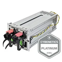

Gemini 1300C Platinum
Gemini Series
Cybenetics Platinum 1300W+1300W 2U CRPS
Redundant Power Supply
●1300W + 1300W 24-hour continuous performance,reliably operating at 50°C
with fully sustained power output.
●2U CRPS form factor: 82mm (W) x 102mm (H) x 239mm (D)
●Cybenetics Platinum certification
●Active PFC (full range)
●All Japanese electrolytic capacitors
●Hot-swappable design
●Convenient pull-out handle bars
●Support PMBus 1.2

SPECIFICATION
SilverStone Gemini Series
Gemini 1300C Platinum
SST-GM1300C-PF
1+1 2U CRPS Redundant Switching Power Supply
Cybenetics Platinum efficiency certified.
01
1.General Description
This specification describes the performance characteristics of the 1300W
AC-DC redundant power supply. The power supply is capable of operating
as a single power supply or in 1+1 parallel hot-swappable operation, and
achieves current sharing in a 1+1 redundant configuration.
※1. Maximum combined power on +3.3V and +5V shall not exceed 200W.
※2. Maximum combined power for all output shall not exceed 1300W.
1.1 Function briefly
Total output
Output
+12V +5V +3.3V -12V +5Vsb
1300W
80.5A(90-170Vac)
105.3A(170-264Vac)
25.0A 25.0A 0.5A 3.0A
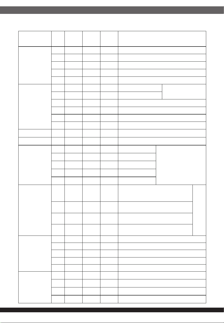
2.1.1 AC input requirements
2.Input Characteristic
02
item measure Minimum Nominal Maximum note
Input Voltage Vac 90 115/230
264
Nom Input Voltage Vac 100 115/230
240
Vin Frequency Hz 47 50/60 63
Nom Vin Frequency Vdc 180 310
Nominal DC input
voltage range
Vdc 240
Maximum input current A / / 14 @90Vac 100% load
Input surge current A / / 45
230Vac/50Hz input,
full load,cold start,
25℃
Power factor 0.99
100%
load,230Vac/50Hz
&115Vac/60Hz
03
Item Unit MIN
Nomin
al
MAX Note
output voltage
V 11.4 12.0 12.6 +12V
V 4.75 5.0 5.25 +5V
V 3.14 3.3 3.47 +3.3V
V -10.8 -12.0 -13.2 -12V
V 4.75 5.0 5.25 +5Vsb
Output current
A 1.5 80.5 90-170Vac
+12Voutput
A 1.5 105.3 170-264Vac
A 0.5 25 +5V
A 0.8 25 +3.3V
A 0 0.5 -12V
A 0.1 3 +5Vsb
Combine
W 200 +3.3V+5V
Hold up time ms 12
+12V&70% load
ripple noise
mV 120
+12V
mV 60
+5.00V
mV 50 +3.3V
mV 120
-12V
mV 50
+5Vsb
Dynamic
response
V 10.8 13.2
+12V output , The dynamic load
range is not greater than 60% ,
Minimum load 1A
0.25
A/us
V 4.5 5.5
+5V output,The dynamic load range
is not greater than 30%。
V 2.97 3.63
+3.3V output , The dynamic load
range is not greater than 30%
V
4.5 5.5
+5Vsb output , The dynamic load
range is not greater than 25%
Switching
machine
overshoot
% 10 +12.00V output
% 10 +5.00V output
% 10 +3.3V output
% 10 -12.00V output
% 10 +5Vsb(Standby) output
capacitive load
uF 11000 +12.00V output
uF
2200
+5.00V output
uF
2200
+3.3V output
uF
350
+5Vsb(Standby) output
2.2.1 AC output requirements
Output Characteristic
04
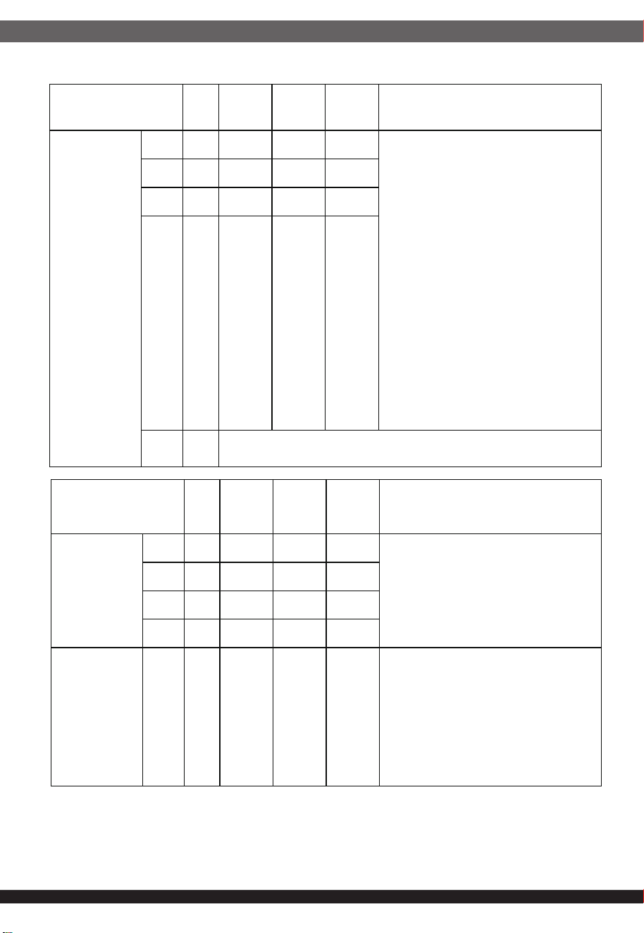
2.2.2 Output protection function
Note: When the rated output power of the equipped module is less than the
output power of the back basket, the OPP/OCP of the module shall prevail.
For +5V and +3.3V overvoltage protection tests, it is forbidden to use the reverse
injection method of the DC input voltage to avoid burning the power supply.
Item Unit MIN
Nomina
l
MAX Note
Over Current
Protection
+5V A 33 45
When overcurrent occurs, the
protective circuit operates and the
power supply self-locks, with no
output at this time; when the fault is
resolved and the power supply is
restarted, the power supply returns
to its normal output state. The power
supply self-locks and there is no
output at this time; when these
reasons are eliminated and the
power supply is restarted, the power
supply returns to the normal output
state. (PSON# resets for at least 1
second; AC shuts down for at least 4
seconds)
+3.3
A 33 45
+5Vs
A 5 16
-12V A 1.5 2.5
+12V A
Follow by module psu
Short Circuit
Protection
/ / / /
automatically protect and lock except +12V
Over Voltage
Protection
+12V V 13.5 15.5
Lock mode
+5V V 5.7 7
+3.3
V 3.7 4.5
-12V V -13.5 -15.5
Over
Temperature
Protection
Yes
℃
60
Turn off the main circuit, self-recovery,
hysteresis is not less than 5℃, +5Vsb
when not turned off
05
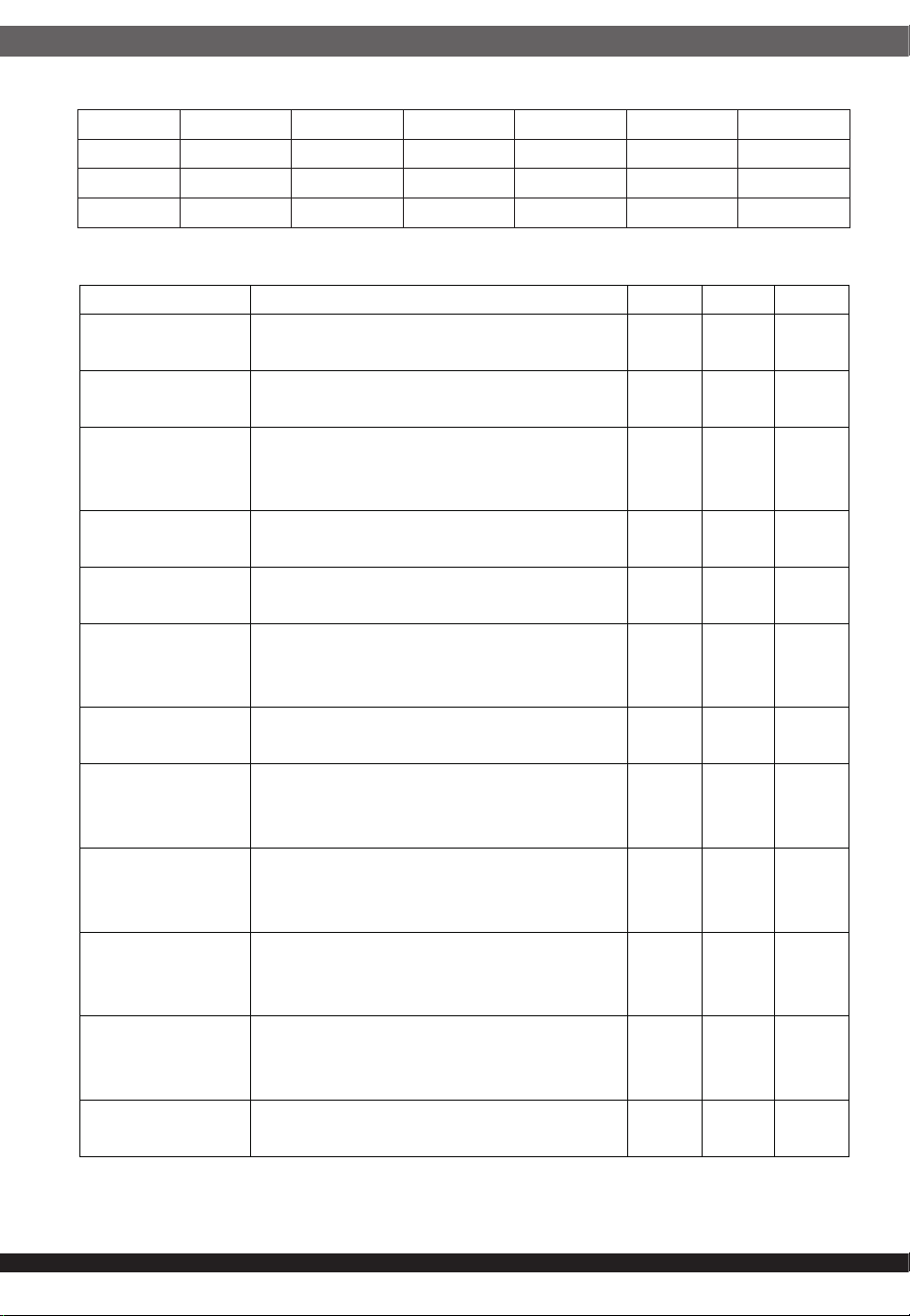
2.2.3 Efficiency
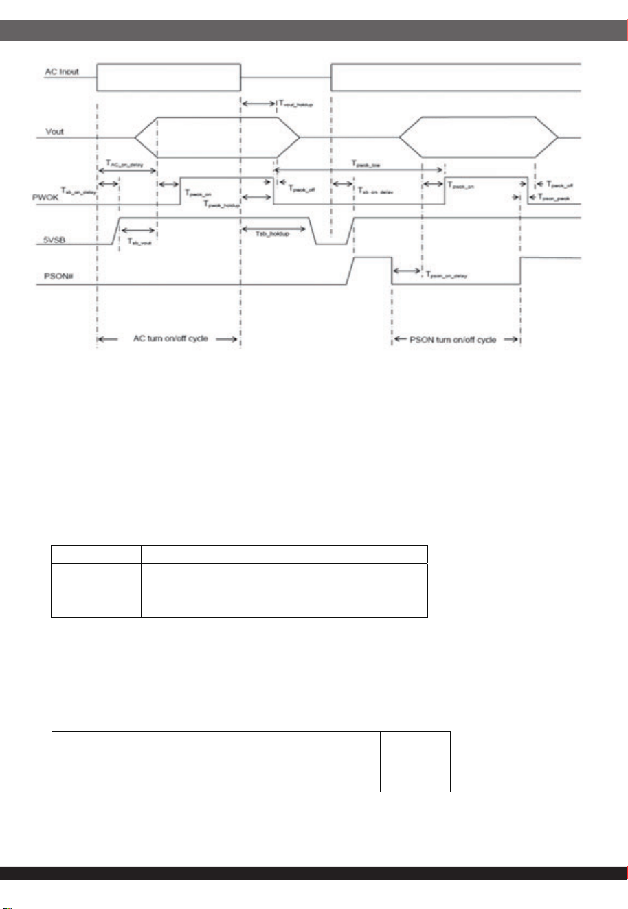
2.3 Timing
*Tvout_rise : The 5Vsb output rise time shall be 1ms to 25ms.
Turn on Description Min Max Units
Tvout rise
Output voltage rise time for all main
output.
3* 70* msec
Tsb_on_delay
Delay from AC being applied to 5Vsb
being within regulation.
1500 msec
Tac_on_delay
Delay from AC being applied to all
output voltage being within
regulation.
2500 msec
Tvout_holdup
Time all main output 12VI voltages
stay within regulation after loss of AC.
13 msec
Tpwok_holdup
Delay from loss of AC to de-assertion
of PWOK.
12 msec
Tpson_on_dela
y
Delay from PSON
active to output voltages within
regulation limits.
5 400 msec
Tpson_pwok
Delay from PSON deactivate to
PWOK being de-asserted.
50 msec
Tpwok_on
Delay from output voltage(12V) within
regulation limits to PWOK asserted at
turn on.
100 500 msec
Tpwok_off
Delay from PWOK de-asserted to
output voltages dropping out of
regulation limits.
1 msec
Tpwok_low
Duration of PWOK being in the de-
asserted state during an off/on cycle
using AC or the PSON signal.
100 msec
Tsb_vout
Delay from 5Vsb being in regulation
to main output being in regulation at
AC turn on.
50 1000 msec
T5Vsb_holdup
Time the 5Vsb output voltage stays
within regulation after loss of AC.
70 msec
Load +5V +3.3V +5Vsb +12V -12V EFF
20% 5A 5A 0.6A 17.86A 0.1A
>90%
50% 12.5A 12.5A 1.5A 44.65A 0.25A
>94%
100% 25A 25A 3A 89.3A 0.5A
>91%
2.4.1 The PWOK signal is a TTL signal. After powering on, when the DC output
voltage of each channel reaches the minimum detection voltage, after a delay
of 100-500mS, the PWOK signal is high level; when a DC output is lower than
the minimum detection level, the PWOK signal is low level.
2.4.2 The PSON signal is a TTL signal, and the power switch is controlled
through the PSON signal. When the PSON signal is low level, the power supply
is turned on; when the PSON signal is high level, the power supply is turned off.
2.4 PWOK signal and PSON signal
06
TTL
logic low level
<
0.8V
,
input current 4mA mA
logic high
level
Between 2.4V and 3.5V, sourcing 200μA
Min. Max.
VIL, input low level voltage 0.0V 0.4V
VIH, input high level voltage 2.4V 3.4V
07
2.5 Alert function
3.1 PMBus definition
3.2 Data interface
1. The status of the indicator light refers to the indicator light of the power module.
It is for reference only. The actual power module specification shall prevail;
2. It is normal for the buzzer to sound briefly when turning on or switching PSON;
Communication speed: maximum 100KHz, Single module information can be read
through output terminal P18 and the following address.
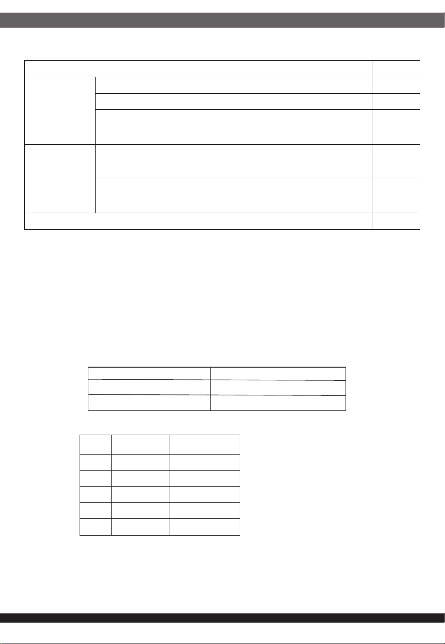
Condition Buzzer
PSU module
insert to the
backplane
when no power
When the power is off and the internal energy is released,
-
Standby state (PS_OFF state)
-
Fault state (PS_ON state), without main output
Alert
PSU module
insert to the
backplane
when power on
When the power is off and the internal energy is released,
-
Standby state (PS_OFF state)
-
Fault state (PS_ON state), without main output
Alert
Module working in good condition /
3 PMbus
MCU PMBus address EEPROM FRU address
0xB0 0xA0
0xB2 0xA2
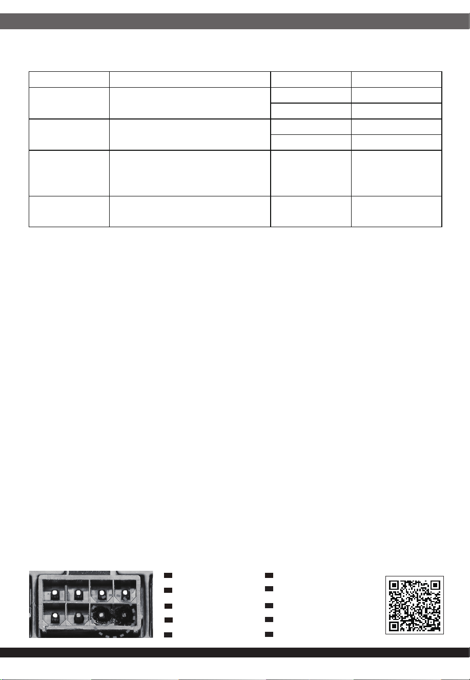
PIN signal Wire color
1 SCL green
2 SDA yellow
3 SMB orange
4 GND black
5 NC none
08
4.Environment
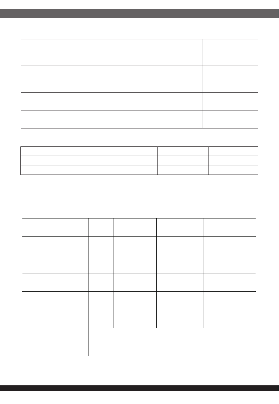
3.3 SMB Alert work status
3.4 SMB alert logic level
Condition
Overall machine
level signal
Parallel or single module, in standby state (PS_OFF) high level
Parallel or single module, in normal working state (PS_ON) high level
When the single module or dual modules are in normal working
condition (PS_ON), the AC input is cut off.
low level
Dual modules work normally in parallel (PS_ON), but the AC input
of one module is disconnected.
low level
Single module or dual module AC normally only has SB (PS_ON),
that is, in fault state
low level
MIN MAX
Logic level low voltage,Isink=4mA 0 0.4V
Logic high low voltage,Isource=200μA 2.4V 3.5V
Item Unit
MIN NORMAL MAX
Operating temperature
℃
0 25 50
Storage temperature
℃
-40 70
Storage humidity
% 5 95
Altitude
m 0 5000
Store altitude
m 0 15200
Heat dissipation method The power supply comes with air-cooling and ventilation mode
(exhaust from DC terminal side to AC input side)
09
5 Electromagnetic compatibility
6 Safety
7 Reliability
8 Dimension
Item requirement Standard Note
(RE)
Frequency:30MHz~1GHz
Class A
EN 55032 230V@50Hz
FCC part 15 120V@60Hz
(CE) Frequency:150KHz~30MHz
Class A
EN 55032 230V@50Hz
FCC part 15 120V@60Hz
SURGE
AC input:
Differential mode:±1KV,
Common mode:±2KV
EN61000-4-5
EN 55024
ESD
contact discharge:±6KV
air discharge:±8KV
EN61000-4-2
EN 55024
6.1 Dielectric strength
6.2 Ground resistance
6.3 touch current
Apply a gradually increasing voltage from 0V to 1500V between the AC line and
the chassis, and then hold it for 1 minute. The insulation should not break down;
if the current caused by the addition of the test voltage increases rapidly in an
uncontrolled manner, that is, the insulation cannot limit the current. , it is consid-
ered that insulation breakdown has occurred; corona discharge or a single
instantaneous flashover is not considered to be insulation breakdown.
value<0.1Ω(32A)
When the input is 264V, the contact current is ≤3.5mA.
When the environment is 25ƫ and 100% load, the mean time between failures
(MTBF) of the power supply is greater than 100,000 hours.
82mm (W) x 102mm (H) x 239mm (D)
9 POWER SUPPLY CONNECTOR OVERUSE DEFINITION
Definition einer Überlastung des
Netzanschlusses
DE
Définition de l'utilisation excessive du
connecteur d'alimentation électrique
FR
Definizione di uso eccessivo del connettore
di alimentazione
IT
Definición de uso excesivo del conector de
la Fuente de alimentación
ES
Определение чрезмерной нагрузки на
коннектор блока питания
RU
電力供給コネクタの使用限度超過に関する説明
JP
⬉⑤կᑨ఼༈䖛ᑺՓ⫼ᅮН
CN
䳏⑤կឝ఼丁䘢ᑺՓ⫼ᅮ㕽
TW
ขีดจำกัดการรองรับการใช้งานของขั้วต่อจากพาวเวอร์ซัพพลาย
TH
전원 공급 커넥터 과용 정의
KR