VERSION A0
Renogy
Pure Sine Wave Inverter
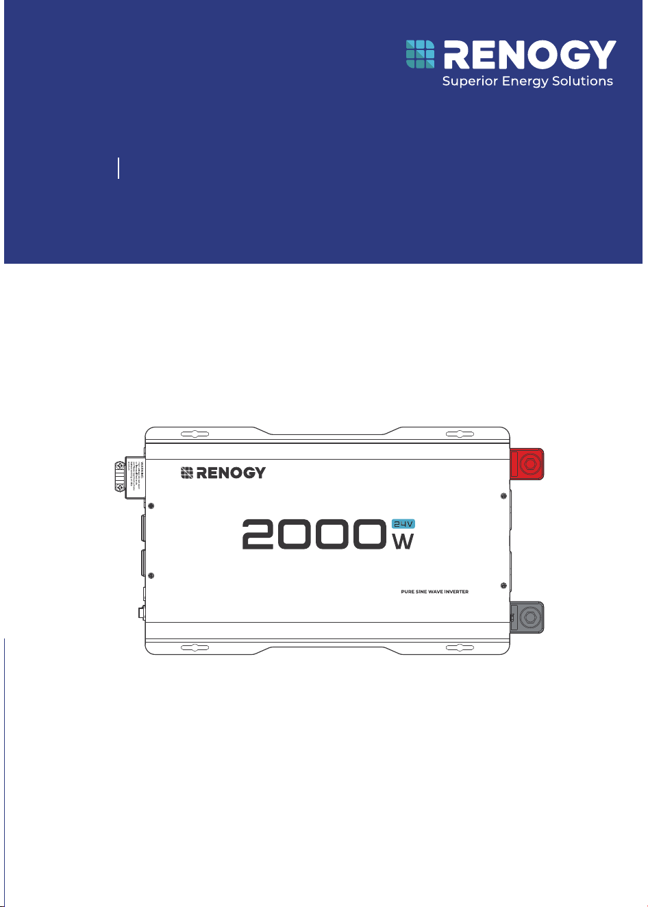
24V 2000W
RIV2420P2-12S
USER MANUAL

-0-
Table of Contents
Before Starting .....................................................................................................................................................0. 1
Disclaimer ..............................................................................................................................................................0. 1
Symbols Used .......................................................................................................................................................02
Introduction .........................................................................................................................................................0. 2
Key Features .........................................................................................................................................................02
SKU .........................................................................................................................................................................0. 2
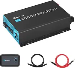
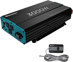
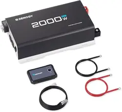
What’s In the Box? ...............................................................................................................................................03
Required Tools & Accessories ...........................................................................................................................03
Get to Know the Pure Sine Wave Inverter ......................................................................................................04
Dimensions ...........................................................................................................................................................0. 5
System Setup ......................................................................................................................................................0. 6
Size a Battery Bank .............................................................................................................................................0. 7
Step 1. Wear Insulating Gloves ..........................................................................................................................0. 7
Step 2. Plan a Mounting Site .............................................................................................................................08
Step 3. Ground .....................................................................................................................................................09
Step 4. DC Wiring .................................................................................................................................................09
Step 5. AC Wiring..................................................................................................................................................1.1
Power On/O! ........................................................................................................................................................1.1
LED Overview & Troubleshooting .....................................................................................................................13
Pure Sine Wave ....................................................................................................................................................1.4
General Safety Information ..............................................................................................................................1. 4
Specifications ......................................................................................................................................................1. 5
Renogy Support ..................................................................................................................................................1. 6
-1-
Before Starting
The user manual contains important operating and maintenance instructions for the R enogy 24V
2000W Pure Sine Wave Inverter (hereinafter referred to as the inverter).
Read the user manual carefully before commissioning and keep it for future re ference. Failure
to follow the instructions or precautions in the user manual may result in electric shoc k, serious
injury or death or damage the inverter, possibly rendering it inoperable.
enclosed operating instructions at the time of printing. However, due to possible continuous
product improvements, Renogy assumes no liability or responsibility for any errors o r
omissions in the manual.
whether direct or indirect, caused by the user not installing and using the product in
accordance with the operating instructions.
attempted repair by unqualified personnel, improper installation or improper operation.
slightly depending on the product version and market region.
notice. For the latest user manual, visit renogy.com.
Disclaimer
RENOGY
Renogy 24V 2000W Pure Sine Wave Inverter User Manual © 2024 Renogy. All rights reserved.
and
are registered trademarks of Renogy.
All information in this user manual is subject to copyright and other intellectua l property
rights of Renogy and its licensors. The User Manual may not be modified, reproduced or
copied in whole or in part without the prior written permission of Renogy and its licensors.
The registered trademarks in the user manual are the property of R enogy. Unauthorized use
of the trademarks is strictly prohibited.
-2-
Symbols Used
The following symbols are used throughout the user manual to highlight important information.
WARNING: Indicates a potentially hazardous condition that could result in injury or death.
CAUTION: Indicates an important procedure for safe and proper installation and operation.
NOTE: Indicates an important step or tip for optimum performance.
Introduction
The Renogy 24V 2000W Pure Sine Wave Inverter (hereafter referred to as the inverte r)
is perfect for most o!-grid systems, whether it’s for a van, a semi-truck, an RV, a ca bin, or any
other remote location that requires power. The inverter converts the direct current store d in the
batteries into usable alternating current for appliances. Thanks to Renogy’s advanced pure sine
wave technology, you can power almost any AC appliance without damaging even your most
sensitive devices.
Key Features
Powerful DC-AC conversion
Continuous rated output power with a maximum conver sion e#ciency of 93 % and up to 2-fold
overvoltage for starting loads.
Guaranteed protection for household appliances
Pure sine wave technology is similar or even better than mains power and can extend the life
of appliances as it delivers a smooth sine wave that won’t damage them. There are no strange
humming noises and your appliances can run smoothly.
Easy to use
Provides an integrated 5V/2.1A USB port, AC power outlet(s), hardwired AC output terminal
and wired remote control port.
SKU
Renogy 24V 2000W Pure Sine Wave Inverter RIV2420P2-12S
-3-
What’s In the Box?
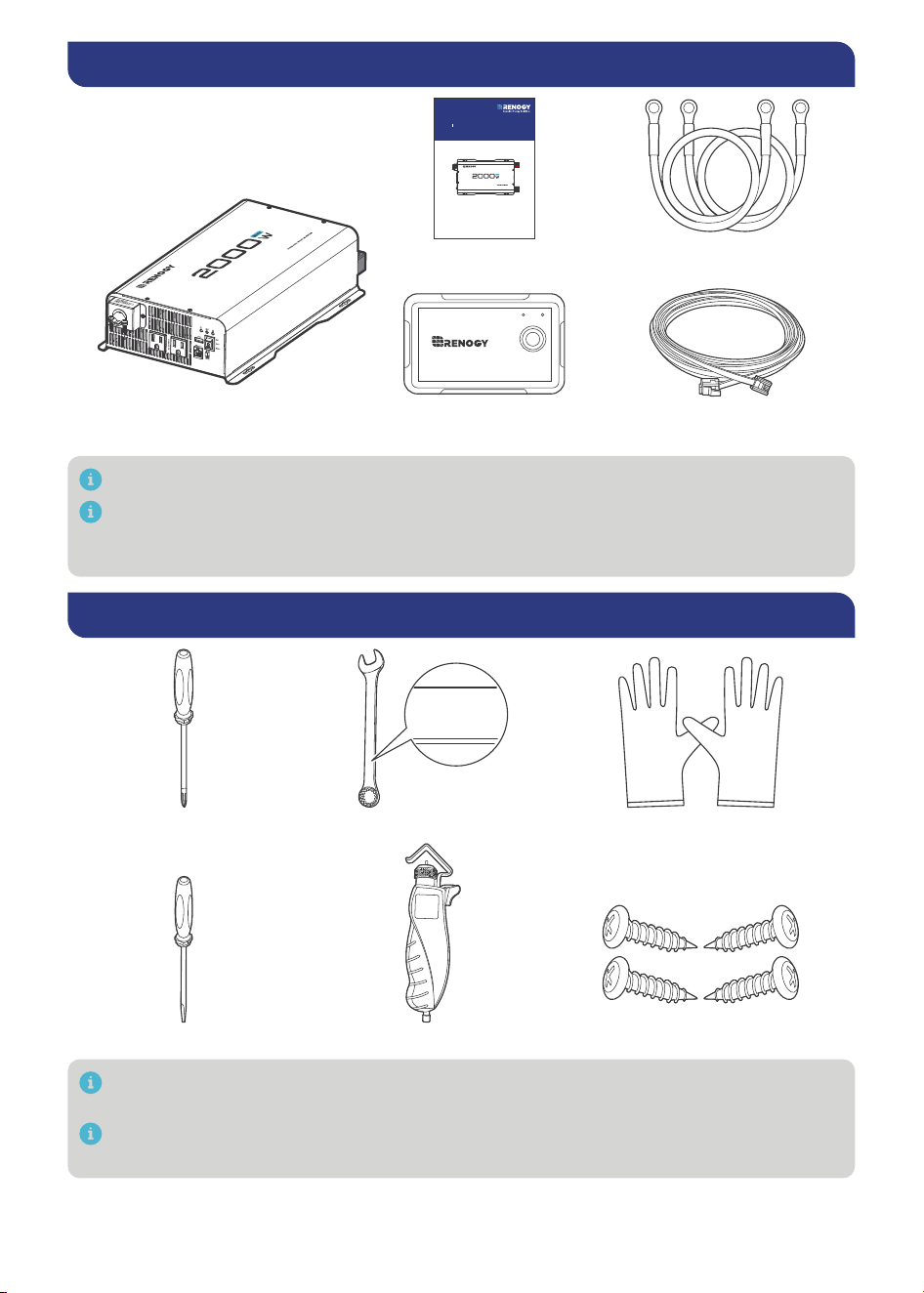
USER MANUAL
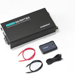
User Manua
Renogy 24V 2000W
Pure Sine Wave Inverter × 1
l × 1
RJ12 Ethernet Cable
2000W:Cables (3 AWG @ 3ft) × 2
(5m) × 1
Wired Remote
Control × 1
ERRON
RMS-P2
Make sure that all accessories are complete and free of any signs of damage.
The accessories and product manual listed are crucial for the installation, excluding
warranty information and any additional items. Please note that the package contents may
vary depending on the specific product model.
Required Tools & Accessories
Insulating GlovesWrench (9/16 in)
1
4
m
m
1
4 mm
14 mm
Phillips Screwdriver (#1)
Slotted Screwdriver (1 mm) Wire stripper
Self-tapping Screws (ST4 or ST6) × 4
Prior to installing and configuring the inverter, prepare the recommended tools,
components, and accessories.
Choose proper mounting screws specific to your installation site. This manual takes self-
tapping screws for wooden walls as an example.
VERSION A0
Renogy
Pure Sine Wave Inverter
24V 2000W
RIV2420P2-12S
-4-
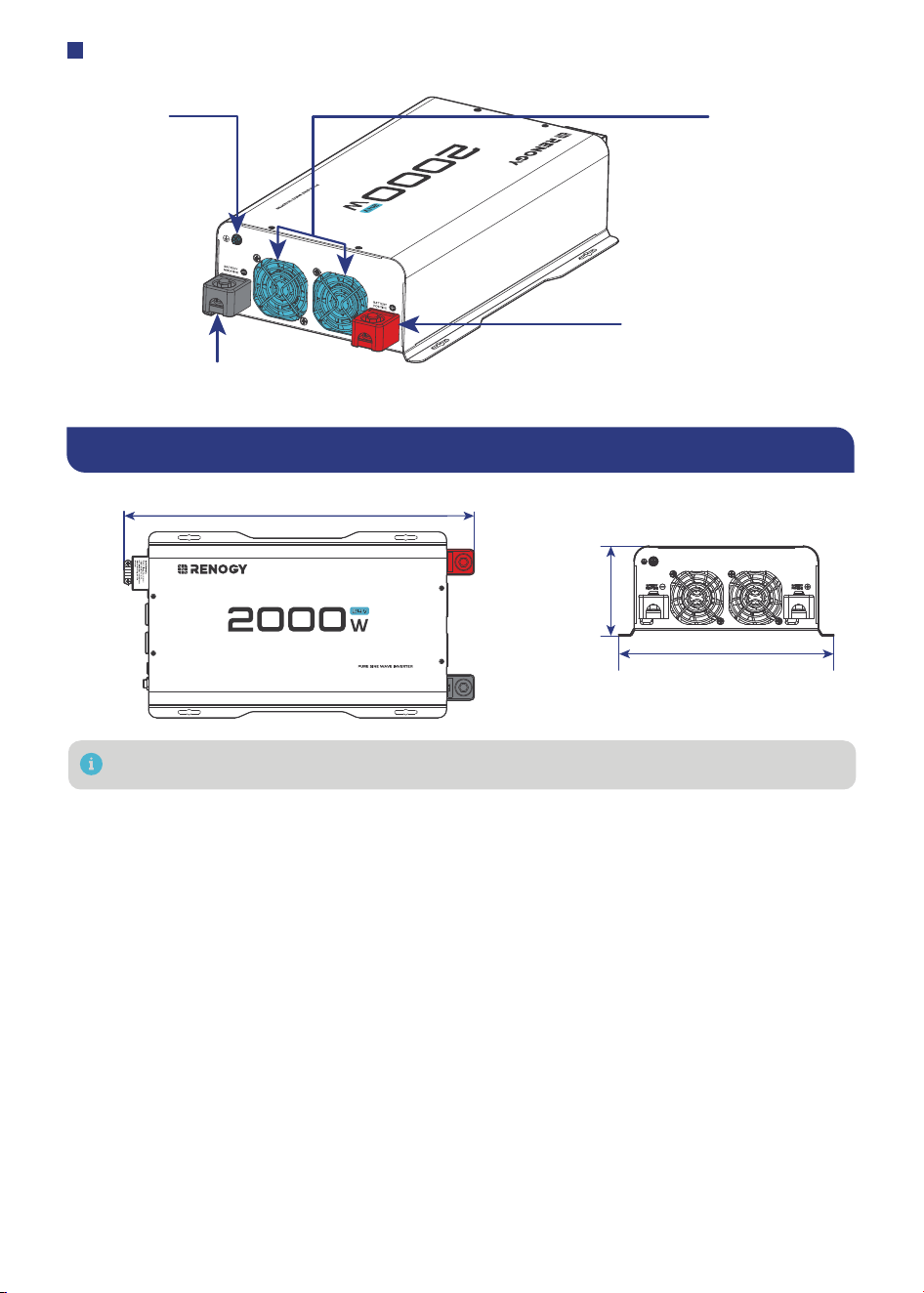
Get to Know the Pure Sine Wave Inverter
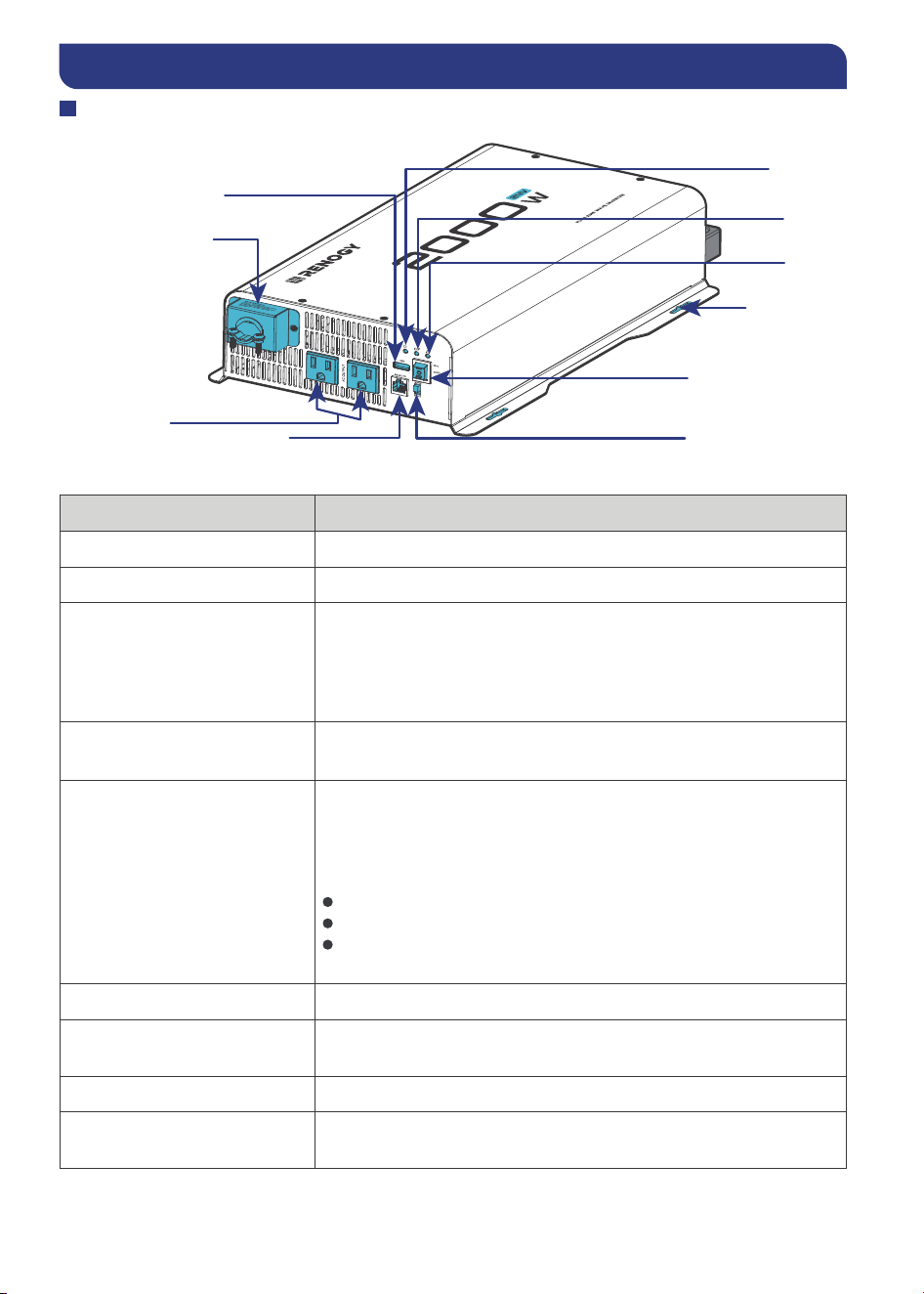
AC Side View
Remote Control Terminal
Fault LED
Power LED
GFCI LED
AC Output Frequency
High Output AC
Terminals
USB Power Port
ON/OFF/REM Switch
Mounting Hole
Part Description
ON/OFF/REM Switch Turns the inverter ON, OFF, or REMOTE.
Power LED Indicates the operation status of the inverter.
Fault LED
Indicates that the inverter shuts down due to overheating,
overload, undervoltage, or overvoltage. Solution: Immediately
turn o! all AC appliances. Allow the inverter to cool before
continuing. Make sure that the ventilation vents are not blocked.
Ensure all cables are of proper sizes and lengths.
High Output AC Terminals
Remove the two screws on the protective cover to access
20A the terminals.
Remove the two screws on the protective cover to access the
terminals.
Terminal layout (facing the front panel)
Left: Live (L)
Middle: Neutral (N)
Right: Ground (G)
Note that Neutral and Ground are bonded inside.
AC Outlet 120V AC, 50/60 Hz, Up to 15A.
USB Power Port
Supplies 5V/2.1 A for charging tablets, smartphones, and other
small appliances.
Remote Control Terminal Connects to the Wired Remote Control.
AC Output Frequency
Configure the AC output frequency of the inverter in accordance
with the frequency of the connected AC loads.
AC Outlet
GFCI LED
Indicates that the ground fault circuit has been interrupted.
In such case, restart the inverter.
-5-
DC Side View
Ground, M4
Cooling Fans
Positive (+) DC Input, M8
Negative (-) DC Input, M8
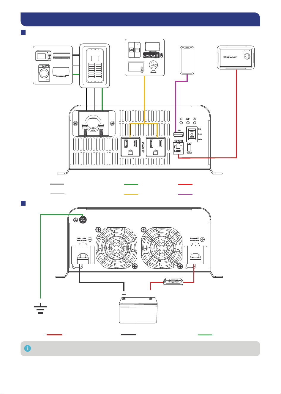
Dimensions
16.93 in (430.3 mm)
8.99 in (228.4 mm)
3.75 in
(
95.3 mm)
Dimension tolerance: ±0.2 in (0.5 mm)
-6-
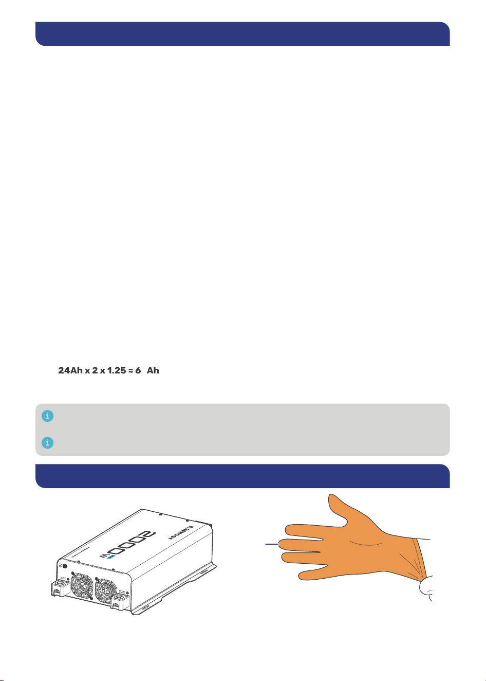
System Setup
AC Side View
Live wire (AC)
Neutral wire (AC)
Ground Remote control
USBAC
Wired Remote
Control
ON ERR
RMS-P2
Loads
(USB)
AC Loads
DC Side View
Positive (DC) Negative (DC) Ground
Ground
The 2000W inverter requires a 150A battery fuse.
+
24V Battery
Battery Fuse
(150A)
AC Loads
Sub-panel
(optional)
-7-
Size a Battery Bank
Battery types and capacity relate to the overall inverter performance. To size a prope r battery
bank, you need to identify the loads that you will be utilizing, as well as an estimate duration
(hours/day) you will be using the load. The inverter is only compatible with 24V battery banks, and
oversizing should be considered due to e#ciency losses.
1.
Determine Your Watts (Amps x Volts)
Every electronic will have a sticker or plate identifying the watts directly (W) or will sho w you
the voltage value (V) as well as amperage (A) which need to be multiplied to get Watts. T he
formula is below:
Watts (W) = Volts (V) x Amps (A)
Example: Fan Watts = 120V ∗ 0.4A = 48Watts
2.
Estimate Load Run-Time in Watt-Hours (Wh)
Estimate how many hours per day you will be using the load and multiply this by your Watts
per load.
Example: Fan Watts x 12 hours = Watt-Hour (Wh)
48W x 12h = 576Wh
Determine Battery Capacity in Amp-Hour (Ah)
Divide your Load Run Watt-Hour result by the battery voltage.
Load Run-Time (Wh)/Battery Voltage (V) = Amp-Hour (Ah)
Use 24V, supported voltage of the inverter as a reference.
576Wh/24V = 24 Ah
Oversize the Battery
The calculated Amp-Hour value represents the minimum size battery capacity to run your
load for your intended time. Note that this assumes 100% use of a battery, which is not
recommended. Assuming 50% depth of discharge, you want to multiply this value by 2 and
you also want to multiply by 1.25 to account for some e#ciency losses.
Formula:
24Ah x Oversize x Efficiency Losses = Recommended Amp-Hour
0
Therefore, a 60Ah battery bank, or close, will be able to support a 12-hour run time while
also prolonging battery life for the best system size possible.
You will need a battery charging source as this is a non-charging inverter and will only work
to deplete the battery.
Actual battery quantities vary by battery capacity and rates of discharge.
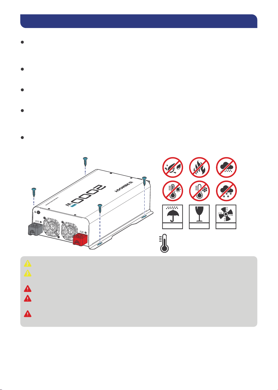
Step 1. Wear Insulating Gloves
Insulating
Gloves
-8-
Step 2. Plan a Mounting Site
Follow the guidelines below:
Cool, dry, well-ventilated area
The inverter must be installed in a site where the fans are not blocked or where they a re not
hit directly by the sun. The site should be free of any kind of moisture with a clearance of a t
least 10 inches around the inverter for adequate ventilation.
Protection against fire hazard
The inverter should be away from any flammable material, liquids, or any other combustible
material.
Close proximity to battery bank
Put the inverter close to batteries banks to prevent excessive voltage drop. Choose a p roper
sized wire going from the battery bank to the inverter.
Limiting electromagnetic interference (EMI)
Ensure the inverter is firmly grounded to a building or vehicle. Alternatively, it can be earth
grounded. Keep the inverter away from EMI receptors such as TVs, radios, and othe r audio/
visual electronics to prevent damage/interference.
Secure mounting
The inverter should be stand-alone or mounted by using the outlying terminals with M4 and
M6 screws on the inverter.
KEEP DRY FRAGILE VENTILATION
-4°F to 131°F / -20°C to 55°C
Do not over-torque or overtighten the terminals. This could potentially damage th e unit.
Refer to the technical specifications for maximum wire sizes on the controller and for the
maximum amperage going through wires.
Ensure the inverter is in the OFF position before connecting to anything.
Do not install the inverter in the same compartment as the battery bank because it could
serve as a potential fire hazard.
Never mount the inverter vertically on a vertical surface since it would present a hazard for
the fan opening, undermining cooling the inverter.
-9-
Step 3. Ground
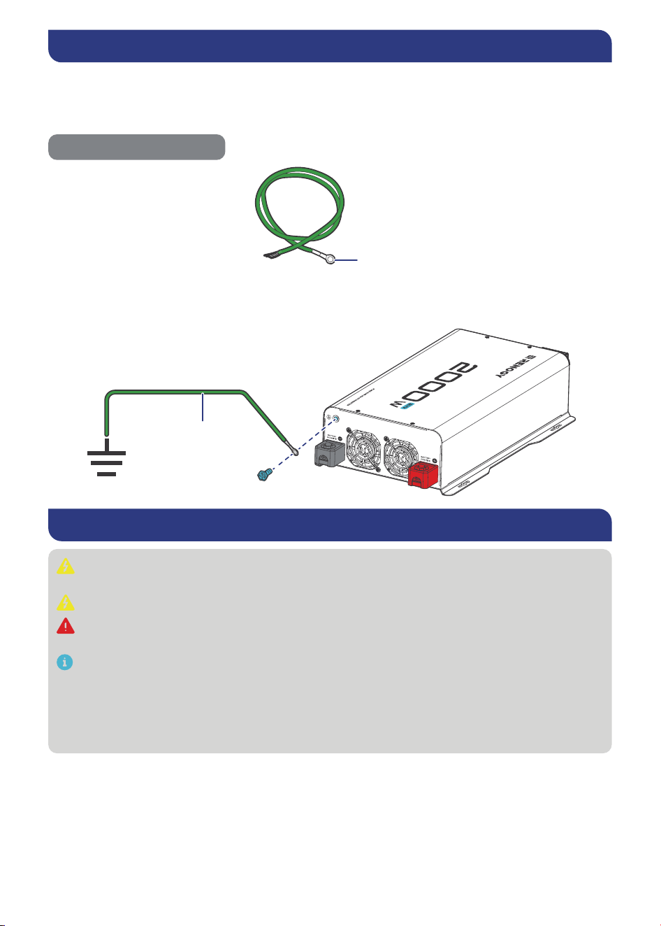
If available, the chassis ground lug should be connected to a ground point such as a vehicle
chassis or boat grounding system. In fixed locations, connect the ground lug to earth ground. The
connections to ground must be tight and against bare metal. Grounding is highly recommended
for both when using the inverter in a mobile application, such as an RV, or in a building.
Empfohlene Komponenten
3/16 in (M4)
Grounding Cable (12 AWG)
Grounding
Grounding Cable
Step 4. DC Wiring
Be careful of the positive and negative poles. Reversing the poles might cause permanent
damage to the inverter and will void the warranty.
For your safety, it is recommended to use a 150A battery fuse.
The inverter is suitable for 24V battery bank systems ONLY. Not following the minimum DC
requirement will cause irreversible damage to the device.
The input terminals of the inverters are embedded with large capacitors. The input circuit
is completed once the terminals are connected to both positive and negative wires. This
commences drawing a heavy current momentarily. As a result, there may be a sparking
occurring even if the inverter is in the o! position. To minimize sparking, it is recommended
that you should choose an appropriate sized wire feeding into the inverters and/or install
an external fuse leading into the inverter.
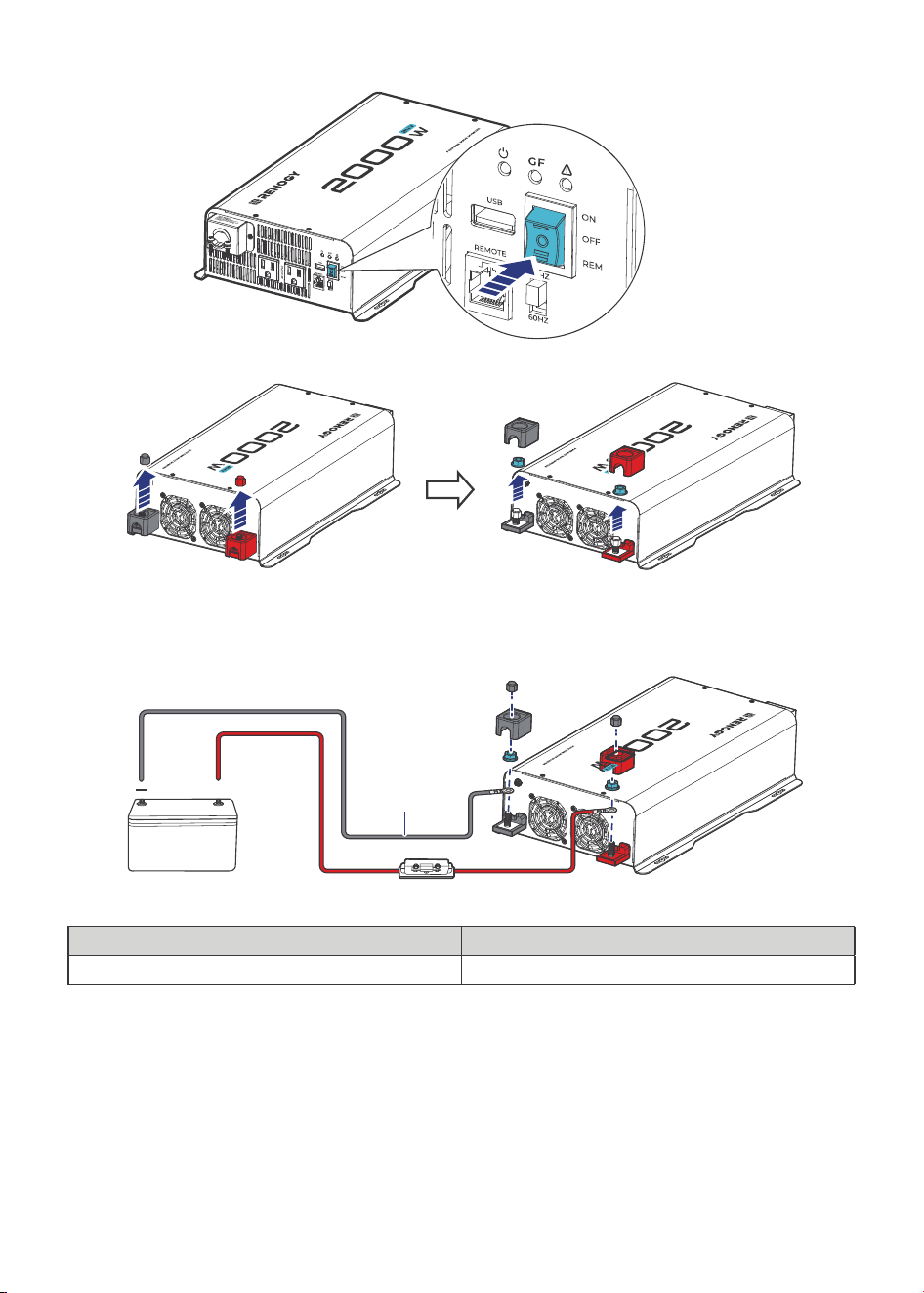
Step 1:
-10-
On the AC side, set the ON/OFF Switch to the OFF position.
Step 2: On the DC side, remove the protection caps.
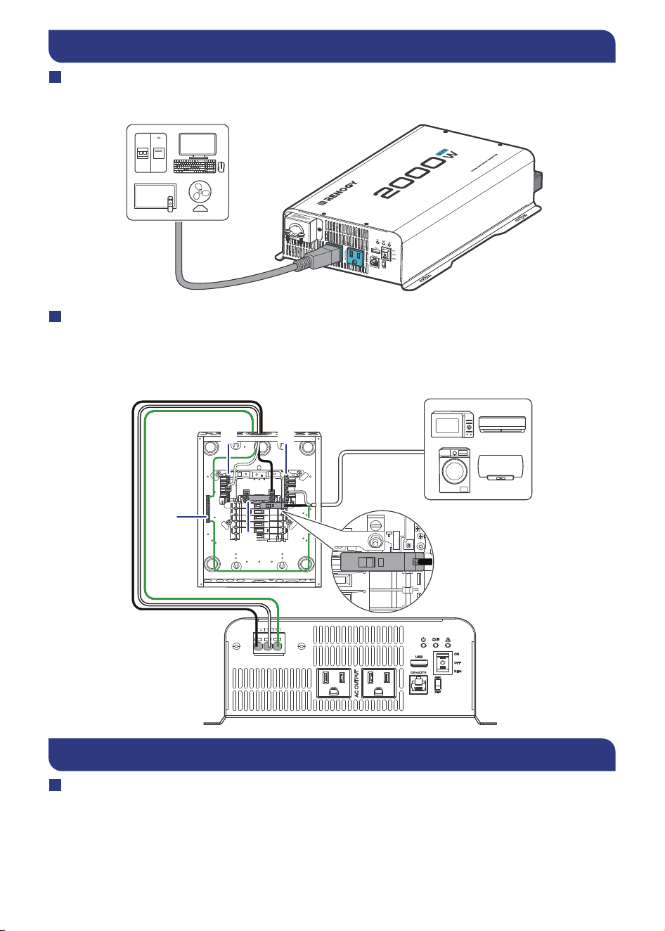
Step 3: Unscrew Positive and Negative DC Input Terminals, connect a battery bank to the
terminals, and tight the terminal screws. Torque: 14(±0.5) N·m
First connect
the negative
+
Battery Fuse (150A)
24V Battery
Cables
(3 AWG @ 3ft)
Cables
2000W: Cables (3 AWG @ 3ft)
Battery Fuse
2000W: 150A
-11-
Step 5. AC Wiring
AC Outlets
You can plug your AC loads directly into the AC Outlets on the inverter’s AC side.
High Output AC Terminals
You can also permanently connect the AC output from the AC hardwire terminal through the
High Output AC Terminals into a load sub-panel or additional AC outlets powered by the 2000W
inverter.
From left to right, the terminal block indicates: Live/Hot (L), Neutral (N) and Ground (G).
G
I/ON
O/OFF
N N
L
I/ON
O/OFF
Power On/Off
Operations on Inverter
After proper battery and AC load connections, you can operate the inverter.
1. On the AC side, rock the ON/OFF Switch to the ON position.
2. The inverter is operating normally.
When finishing using the inverter, power o! the AC loads first, and then rock the ON/OF F Switch
to the OFF position.
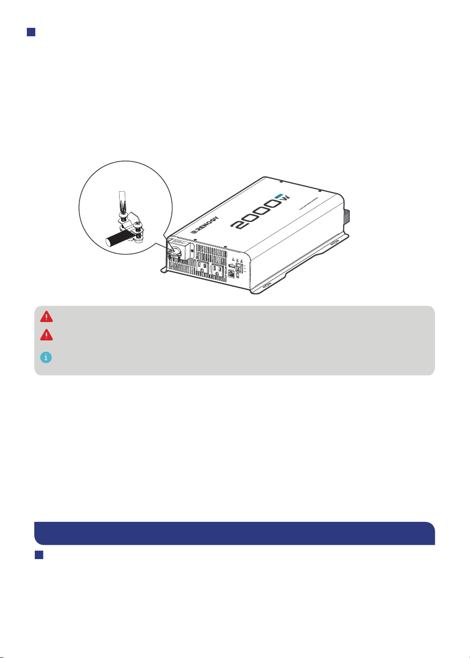
The AC Output Port with cable clamps to ensure that the wiring connections
remain secure and do not come loose due to vibrations.
Step 1: Loosen the screws on a cable clamp with a Phillips Screwdriver.
Step 2: Lift the clamp, and run the cables through the clamp.
(You will need 1 x 3 prong (10 AWG recommended Black, White, Green) ac cables not
provided with this product. Measure the required length for your particular application.
for ac output of the inverter.SJT0 and SJT,SJ0 are recommended wire)
Step 3: Secure the clamp by fastening the screws.
How to Properly Install Cable Clamps?
14.16in-ibs
(1.6N-m)
Do not use the bare wires if there is any visible damage.
Do not use SP-3, SPT-3 type wire
The screw torque of a cable clamp is 14.16 in·lbs (1.6 N·m).
Do not over tighten the screws to prevent damage
-12-
Power On/Off
Operations on Inverter
After proper battery and AC load connections, you can operate the inverter.
1. On the AC side, rock the ON/OFF Switch to the ON position.
2. The inverter is operating normally.
When finishing using the inverter, power o! the AC loads first, and then rock the ON/OF F Switch
to the OFF position.
-13-
When the inverter turns on, it is normal to see the fans run for a second and hear a beep.
Avoid powering on the inverter with the load (electronic devices) already switched on. This
may trigger an overload since some electronic devices have an initial high power surge to
start.
When switching o! the inverter, turn o! the electronic devices first. Although the inverter
is o!, the terminal capacitors will still have a charge, so the DC and AC terminals must be
disconnected if altering the circuitry.
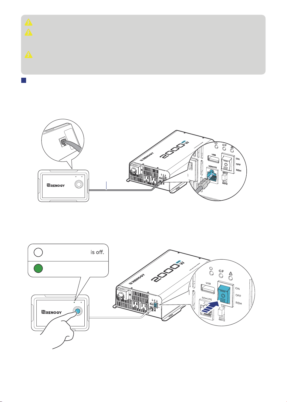
Wired Remote Control
The Wired Remote Control gives you the opportunity to power on/o! the inverter from a distance
(approximately 16.4 ft / 5 m).
Note that the inverter ON/OFF switch should be in the REM position.
Step 1: Connect the Wired Remote Control to the inverter via the Remote Control Connector .
ON ERR
RMS-P2
RJ12
Ethernet
Cable
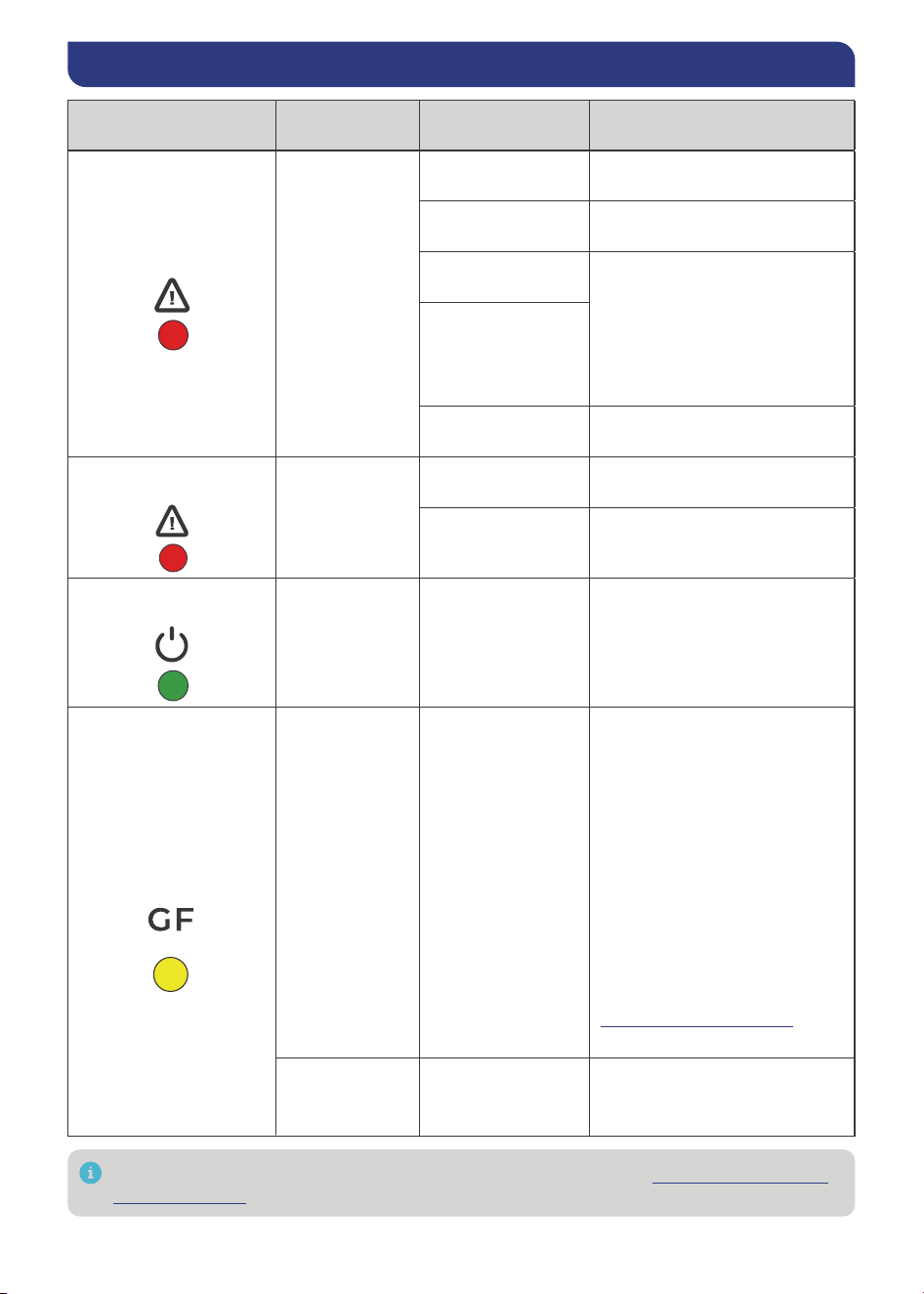
Step 2: Rock the ON/OFF Switch to the REM position, and you can power on/o! the inverter via
the Wired Remote Control.
ON ERR
RMS-P2
OFF:
ON: The inverter is on.
The inverter
-14-
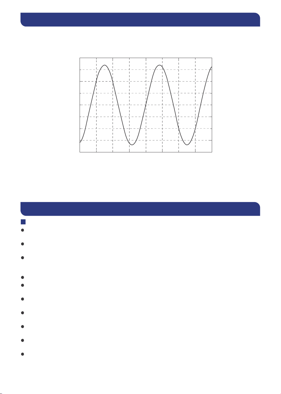
LED Overview & Troubleshooting
LED Status Alarm
Protection &
Alarm
Inverter Status
Fault LED in solid red
Long steady
beeping sound
Overtemperature
protection
No output from the inverter.
Undervoltage
shutdown
No output from the inverter.
Overload
protection
No output from the inverter
output side. After 5s, the
inverter automatically restarts.
After five times of failed
restart, the inverter needs
to be restored by manually
turning it on.
Short circuit
protection
Undervoltage
protection
No output from the inverter.
Fault LED in Quick
flashing
Red LED Quick
flashing
Input voltage is
below 22.4V.
Keep input voltage above
22.4V.
Input voltage is
above 32.7V.
Keep input voltage below 32.7V.
Power LED in solid
green and fault LED o!
No sound
Inverter recovers
output
Normal output from the
inverter output side.
For further assitance, contact Renogy technical support service at https:// www.renogy.
com/contact-us
.
GFCI LED in solid
yellow
Long steady
beeping sound
GFCI protection
1. No output from the inverter.
2. Disconnect all appliances,
and use the ON/OFF/Remote
Attempt to connect various
appliances one at a time,
observing if the yellow LED on
the inverter remains
illuminated. If it stays o!, this
suggests a current leakage
issue with one of the
appliances.
reach out to Renogy via
renogy.com/
contact-us
for further assistance.
No sound and
the inverter is
o!
GFCI tripped
Disconnect appliances, and
use the ON/OFF/Remote
switch to reset the inverter.
switch to reset the inverter.
If the LED remains on, kindly
-15-
Pure Sine Wave
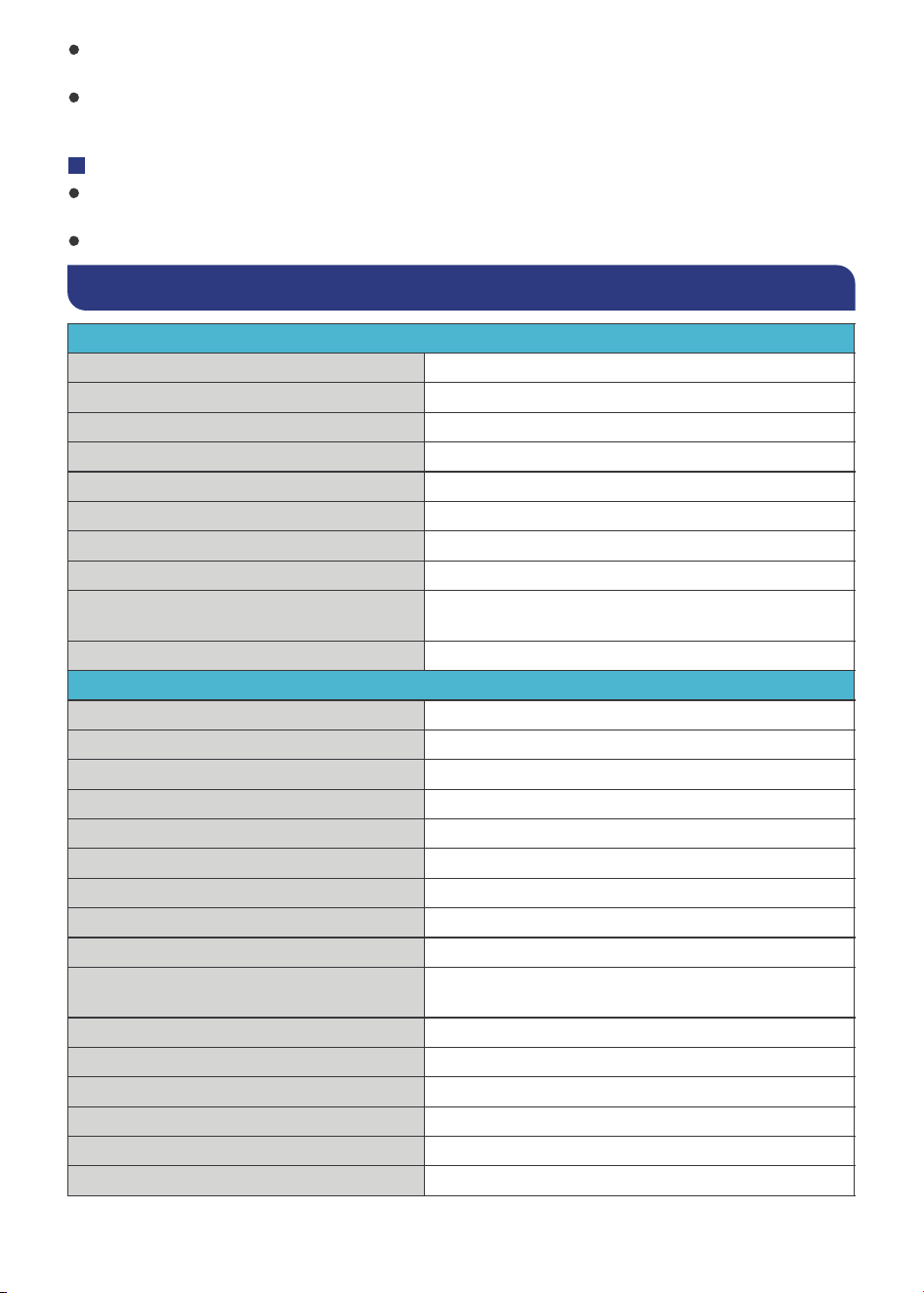
The inverter outputs a pure sine wave similar to the waveform of the grid power. In a pure sine
wave, the voltage rises and falls in a smooth fashion with very low harmonic distortion and c leaner
utility-like power.
This technology allows the inverter to supply electronic devices that require a high quality
waveform with little harmonic distortion. In addition, the technology enables the inverter to be
more e#cient than traditional ones, allowing you to use less energy to supply more devices.
The inverter can provide su#cient, stable power for tools, fans, lights, computers, and other
electronics without any interference.
General Safety Information
WARNING
Have the inverter installed by a qualified technician in accordance with the local and nati onal
electric codes (NEC).
There are no serviceable parts for this inverter. Do not disassemble or attempt to repai r the
inverter.
Ensure all connections going into and from the inverter are tight. There may be sparks when
making connections; therefore, there should not be flammable materials or gases near the
installation site.
The inverters are suitable for 24V battery banks ONLY.
Always ensure the inverter is in OFF position and disconnect all AC and DC devices associated
with the inverter.
Never connect the AC output of the inverter directly to an Electrical Breaker Panel or Load
Center which is also fed from the utility power or generator.
Please confirm the polarity of the devices before connection. A reverse polarity contact can
cause injury and damage the device.
Be careful when touching bare terminals of capacitors as they may retain high lethal voltages
even after power is removed.
Do not let the positive (+) and negative (-) terminals of the battery touch each other. Use onl y
deep-cycle sealed lead-acid, flooded, gel, or lithium batteries.
Risk of explosion! Never install the inverter in a sealed enclosure with flooded batteries! Do no t
install in a confined area where battery gases can accumulate.
200
150
100
50
0
-50
-100
-150
-200
-0.02 -0.015 -0.01 -0.005 0 0.005 0.01 0.015
0.02
Pure Sine Waveform
Time (Seconds)
Amplitude (Volts)
-16-
Be careful when working with large lead acid batteries. Wear eye protection and have fresh
water available in case there is contact with the battery acid.
Overcharging and excessive gas precipitation may damage the battery plates and activate
material shedding on them. Too high of an equalizing charge or too long of one may cause
damage. Carefully review the requirements of the specific battery in use.
VORSICHT
Install the inverter in a well-ventilated, cool, and dry environment. Make sure the f ans of the
inverter and the ventilation holes are not blocked.
Do not expose the unit to rain, moisture, snow, or liquids of any type.
Specifications
General Data
Model RIV2420P2-12S
Output Waveform Pure Sine Wave
AC Terminals 2x AC Socket & Terminal Block
DC Terminals M8 x 25 mm
Operating Temperature -4°F to 131°F / -20°C to 55°C
Storage Temperature -40°F to 158°F / -40°C to 70°C
Humidity Max 95%, non-condensing
Cooling Thermally Controlled Fans
Dimensions (L x W x H)
16.93 x 8.99 x 3.75 in
430.3 x 228.4 x 95.3 mm
Weight
10.14lb /4,6 Kg
Electrical Data
Continuous Output Power 2000W
Continuous Output Current 16.7A AC
Total Harmonic Distortion (THD) < 3%
Power Factor 1
Surge Rating 4000W (@2S)
Output Voltage 120V AC
Output Frequency 50Hz / 60Hz
Rated Battery Input Voltage 24V DC
Battery Input Voltage Range 23V to 30.7V DC
Maximum Continuous Battery Output
Current
106A
Inverter Efficiency Max. 92%
Full Load Efficiency 89%
Power Consumption < 19.2W
Battery Overoltage Shutdown 33.3 V (±0.5 V) DC
Battery Low Voltage Alarm 22.4 V (±0.5 V) DC
Battery Low Voltage Shutdown 21.8 V (±0.5 V) DC
-17-
Wired Remote Data
Front Plate Dimensions 2.8 x 4.3 x 1.3 in / 70 x 110 x 31.8 mm
Wired Length 16.4 ft / 5 m
Renogy Support
To discuss inaccuracies or omissions in this quick guide or user manual, visit or contact us at:
renogy.com/support/downloads
contentservice@renogy.com
Questionnaire Investigation
To explore more possibilities of solar systems, visit Renogy Learning Center at:
renogy.com/learning-center
For technical questions about your product in the U.S., contact the Renogy technical support
team through:
renogy.com/contact-us
1(909)2877111
For technical support outside the U.S., visit the local website below:
Canada ca.renogy.com China www.renogy.cn
Australia au.renogy.com Japan renogy.jp
South Korea kr.renogy.com Germany de.renogy.com
United Kingdom
uk.renogy.com Other Europe eu.renogy.com
RENOGY.COM
Renogy aims to empower people around the world through education and distribution of
DIY-friendly renewable energy solutions.
Renogy Power Plus allows you to stay in the loop with upcoming solar energy innovations,
share your experiences with your solar energy journey, and connect with like-minded
people who are changing the world in the Renogy Power Plus community.
We intend to be a driving force for sustainable living and energy independence.
carbon footprint by reducing the need for grid power.
Renogy Empowered
Live Sustainably with Renogy
Did you know? In a given month, a 1 kW solar energy system will...
Save 170 pounds of coal from being burned
Save 300 pounds of CO from being released into the atmosphere
Save 105 gallons of water from being consumed
@Renogy Solar @Renogy
Renogy Power
PLUS
Renogy reserves the right to change the contents of this manual without notice.