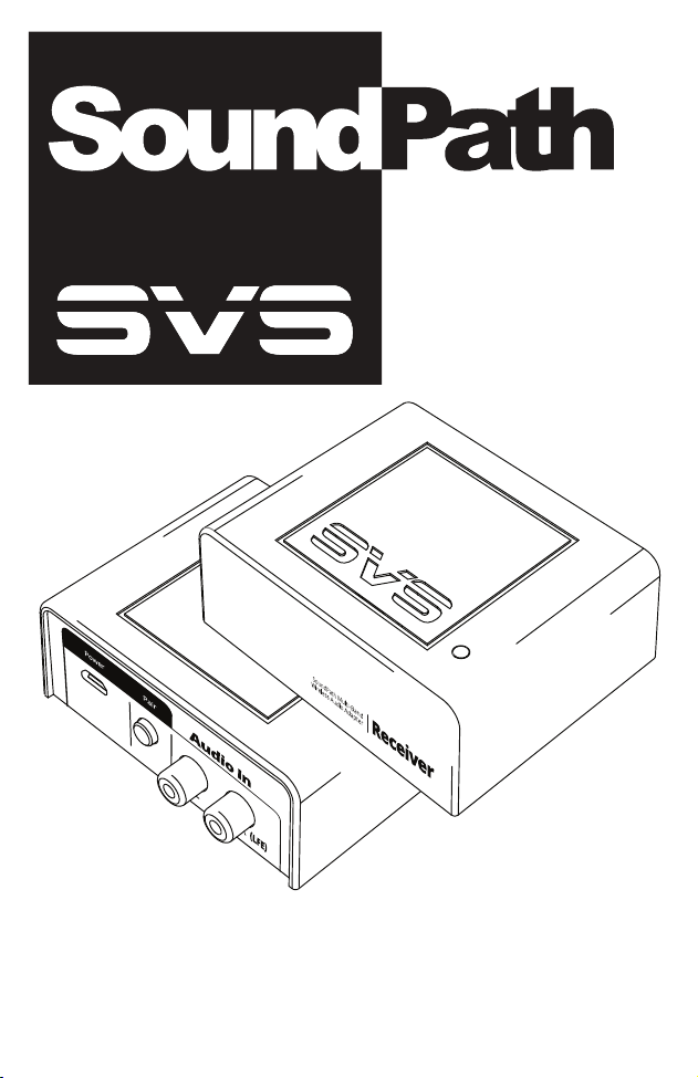
MULTI-BAND
WIRELESS AUDIO
ADAPTER
Owner’s Manual

Thank you for choosing SVS!
Congratulations on bringing home the SVS SoundPath Multi-Band Wireless Audio Adapter, the
best solution available for eliminating subwoofer cable clutter without sacrificing performance.
Because it passes a full-range Left/Right stereo signal, you can also wirelessly connect stereo
speakers, powered surround sound speakers, amplifiers, and any stereo audio component.
The SoundPath Multi-Band Wireless Audio Adapter operates in the 5.2 GHz and 5.8 GHz bands and
is highly resistant to all forms of wireless interference from common household devices. Seamless
switching between channels ensures your subwoofer, speakers or other audio components will
remain connected in even the most congested wireless environments so you can always enjoy
uninterrupted listening experiences.
Installation requires only a few simple steps. If you have questions about subwoofer or speaker
placement, system optimization or installing the SVS SoundPath Multi-Band Wireless Audio
Adapter, please contact the SVS Sound Experts tech support.
[email protected] | 877.626.5623 | www.svsound.com
Specifications & Features
Adapter Includes
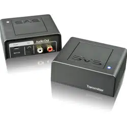
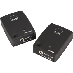
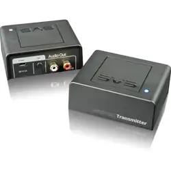
» Multi-Band Wireless Audio Transmitter
» Multi-Band Wireless Audio Receiver
» Mono RCA to RCA interconnect cable (x2)
» USB A to micro B power cable for power adaptor (x2)
» 5V DC power adapter with USB A Connector (x2)
» 3M hook and loop fasteners for securing devices (x2)
What You Will Need
» Output device (subwoofer, powered speakers or amplifier)
» Source device (AV receiver, surround processor, or 2-channel pre-amp with a subwoofer pre-out
or L/R line level pre-out)
Specifications
Operating Voltage
RF Frequency Band
Sample Rate
Resolution
Working Distance
Transmitter analog input level
Receiver analog output level
Frequency Response
Latency
THD+N
SNR (dB)
Receiver
Minimum power requirement:
5V @ 1A
Multi-Band (46 Channel auto switching
between 5.2 and 5.8 GHz)
48kHz
24 bit
up to 165 ft (50 m); line of sight
N/A
Maximum 2Vrms
3Hz – 20 kHz +/- 0.5 dB
< 15 milliseconds
< 0.02% (10Hz – 20kHz)
+ 104 dB 10Hz – 20kHz
Transmitter
Minimum power requirement:
5V @ 1A
Multi-Band (46 Channel auto switching
between 5.2 and 5.8 GHz)
48kHz
24 bit
up to 165 ft (50 m); line of sight
Maximum 2Vrms
N/A
3Hz – 20 kHz +/- 0.5 dB
< 15 milliseconds
< 0.02% (10Hz – 20kHz)
+ 104 dB 10Hz – 20kHz
General Placement and Set-up Tips
» Place the subwoofer, powered speaker or amplifier at its intended location.
» Try to maintain line-of-sight (no walls or solid barriers) between the transmitter
and receiver for best results.
» Receiver should be within 165 feet (50 meters) of transmitter for best results.
» Avoid placing the transmitter next to devices that could create signal interference, such as mobile
phones, baby monitors, RF wireless phones and Wi-Fi routers.
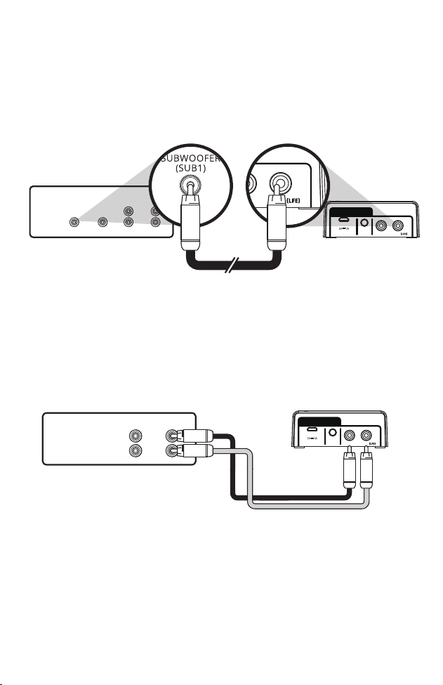
Connecting the Wireless Transmitter to an AV processor
1. Connect the mono RCA cable to the subwoofer out or LFE channel of the AVR or pre-amp
processor to the R/LFE input on the wireless transmitter.
2. Connect the USB A to Micro B cable to the wireless transmitter and the included 5 VDC power
supply. You can also use an available USB charging port with an output of at least 5V @ 0.2A
3. If using the 5 VDC power supply, connect to nearby power outlet.
Connecting the Wireless Transmitter to a 2-channel stereo pre-amp
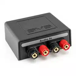
1. Connect a stereo pair of RCA cables (SVS SoundPath Stereo RCA Audio Cable Pair sold
separately) to the L/R line level pre-outs of the 2-channel stereo pre-amp and to L/R inputs
on the wireless transmitter.
2. Connect the USB A to Micro B cable to the wireless transmitter and the included 5 VDC
power supply. You can also use an available USB charging port with an output of at
least 5V @0.2A
3. If using the 5 VDC power supply, connect to nearby power outlet.
CENTER
REAR FRONT
SUBWOOFER
(SUB1)
LINE LEVEL OUTPUTS
INPUT OUTPUT
Audio In
L
Power Pair
R
RECEIVER/PREAMP
Audio In
(Transmitter)
L
Power Pair
R
LINE LEVEL OUTPUTS
REAR FRONT
R
L
RECEIVER/PREAMP
Audio In
(Transmitter)
L
Power Pair
R
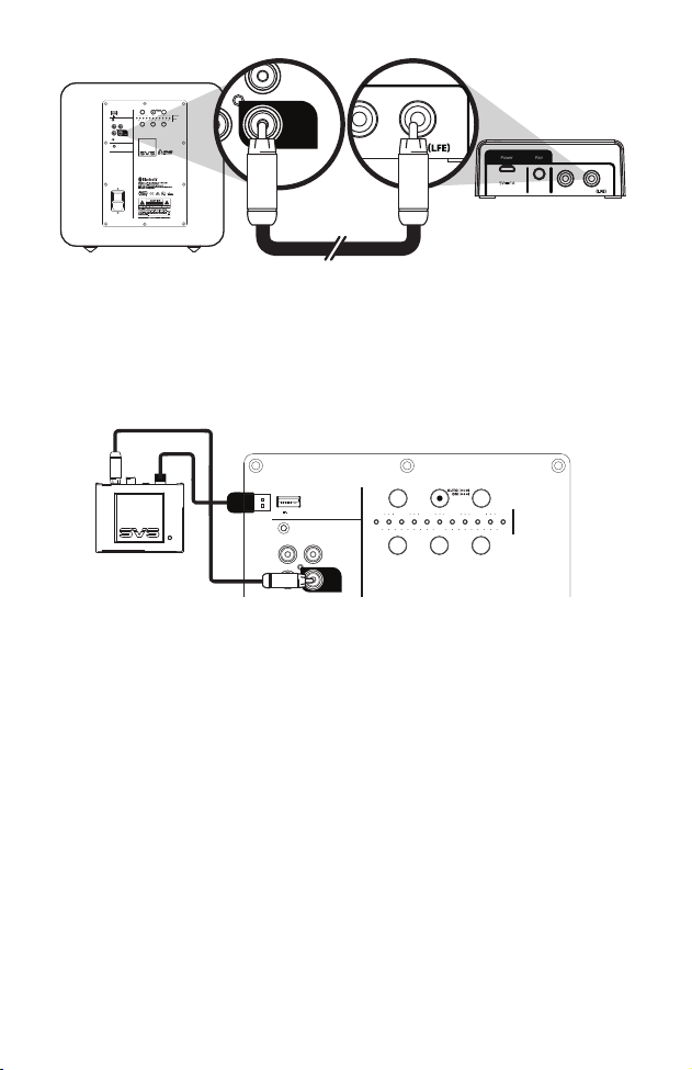
4. If using an SVS subwoofer with a SoundPath Wireless Audio Adapter power output, you can
connect the USB A to Micro B cable to the wireless receiver and directly to the rear panel of
the SVS subwoofer.
Connecting the Wireless Receiver to your Subwoofer
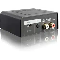
1. Connect the mono RCA cable to the LFE input on the subwoofer and to the R/LFE output on
the wireless receiver.
2. For 2-channel stereo pre-amp applications connect a stereo RCA cable to both the L and R
subwoofer inputs and to the L and R outputs on the wireless receiver. – CABLE NOT
SUPPLIED
3. Connect the USB A to Micro B cable to the wireless receiver and the 5 VDC power supply.
Audio Out
(Receiver)
L
Power Pair
R
ONOFF
R
3V-12V | AC/DC
L
+
VOL
LOW
PASS
LOW PASS
PHASE
PHASE
0°
90° 180°
30Hz 40Hz 60Hz 90Hz 140Hz LFE
_
LINE LEVEL
INPUT OUTPUT
TRIGGER INPUT
SVS SOUNDPATH WIRELESS
AUDIO ADAPTER
STA-550 D
LFE
5V 150mA
RL
INPUT OUTPUT
LFE
Audio Out
L
Power Pair
R
ONOFF
R
3V-12V | AC/DC
L
+
VOL
LOW
PASS
LOW PASS
PHASE
PHASE
0°
90° 180°
30Hz 40Hz 60Hz 90Hz 140Hz LFE
_
LINE LEVEL
INPUT OUTPUT
TRIGGER INPUT
SVS SOUNDPATH WIRELESS
AUDIO ADAPTER
STA -5 50 D
LFE
5V 150mA
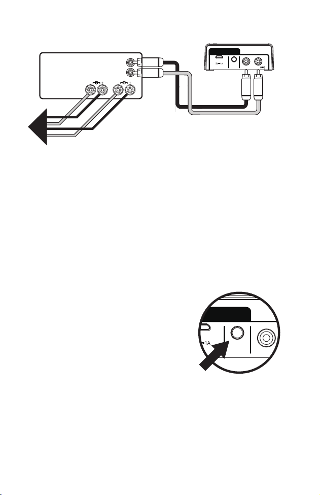
Connecting the Wireless Receiver to Power Amplifiers or Powered
Speakers
1. For 2-channel applications Connect a stereo pair of RCA cables (SVS SoundPath Stereo
RCA Audio Cable Pair sold separately) to the L/R line level inputs on the stereo amplifier or
powered speaker inputs and to L/R inputs on the wireless transmitter
2. Connect the USB A to Micro B cable to the wireless receiver and the 5 VDC power supply.
3. Connect the 5 VDC power supply to a nearby outlet.
Pairing the Transmitter and Receiver
1. The transmitter and receiver are synched at the time of manufacture and will pair
automatically when connected and powered on.
2. Successful pairing will be indicated by a steady blue light on the transmitter and receiver.
3. A slow flashing light indicates the units are not paired. To re-pair the units, perform the
following actions:
» Once your transmitter and your receiver are
connected and powered on, press and hold the
PAIR button located on the back of the transmitter
until the blue LED light located on the top of the
unit flashes quickly.
» Within 30 seconds, press and hold the PAIR button located on the back of the receiver.
» When your transmitter and receiver are paired, the wireless status lights on the top of
both units will turn solid blue.
» Your SVS SoundPath Multi-Band Wireless Audio Adapter transmitter and receiver are now
set up and ready to use.
LINE LEVEL INPUTS
SPEAKER LEVEL
OUTPUTS
R
L
TO
SPEAKERS
POWER AMPLIFIER
Audio Out
(Receiver)
L
Power Pair
R
INPUT OUTPUT
Audio In
L
Power Pair
R

FAQs and Troubleshooting
Does my AV processor correct for the latency (time delay) of the wireless unit?
Yes, this will be reflected in a longer than normal subwoofer distance, as shown under the set-up
section of the AV processor. An additional 14 to 20 feet (beyond the actual subwoofer distance)
is normal.
I keep hearing interference artifacts or experiencing signal drop-outs – how can I correct for
this?
Always try to keep a line-of-sight between the transmitter and receiver units with no hard
barriers or walls between them.
Avoid placing other wireless devices near the units like wireless phones, mobile phones, WIFI
routers, baby monitors, etc.
My SoundPath Multi-Band Wireless Audio Adapter is connected and plugged in, but doesn’t
seem to be working.
Verify that the LED status lights on the Transmitter and Receiver are illuminated. If either of
them are off, it might not be receiving power. Make sure there is no visible damage to the
power cable or USB connectors, and check to be sure both are plugged into functioning
electrical outlets. Both Transmitter and Receiver need to have constant power to function
properly.
Warranty & Support
» 5-YEAR UNCONDITIONAL WARRANTY
» SVS offers the industry’s most comprehensive warranty on all our products. SVS warrants the
SoundPath Multi-Band Wireless Audio Adapter and all products to be free from defects in the
workmanship for 5 years from date of purchase.
» This, and all the SVS customer Bill of Rights can be viewed online at:
www.svsound.com/bill-of-rights.
Share Your Thoughts
SVS Sound Experts are standing by to assist you with set-up, optimization and any questions you
have about the SoundPath Multi-Band Wireless Audio Adapter. They can be reached by phone,
email or chat via the options below.
[email protected] | 877.626.5623 | www.svsound.com
Write a review at svsound.com
Post at facebook.com/SVSound
Post (formerly tweet) @SVS_Sound
Follow at instagram.com/SVS_Sound
Subscribe at youtube.com/SVS_Sound
Safety Instructions
» Read these instructions.
» Keep these instructions.
» Heed all warnings.
» Follow all instructions.
» Do not use this apparatus near water.
» Clean only with dry cloth.
» Do not block any ventilation openings. Install in accordance with the manufacturer’s instructions.
» Do not install near any heat sources such as radiators, heat registers, stoves, or other apparatus (including amplifiers) that
produce heat.
» Do not defeat the safety purpose of any polarized or grounding-type plug. A polarized plug has two blades with one wider
than the other. A grounding type plug has two prongs and a third grounding point. The wide blade or the third prong are
provided for your safety. If the provided plug does not fit into your outlet, consult an electrician for replacement of the
obsolete outlet.
» Protect the power cord from being walked on or pinched particularly at plugs, convenience receptacles, and the point where
they exit from the apparatus.
» Only use attachments/accessories specified by the manufacturer.
» Use only with the cart, stand, tripod, bracket, or table specified by the manufacturer, or sold with the apparatus. When a cart
is used, use caution when moving the cart/apparatus combination to avoid injury from tip-over.
» Unplug this apparatus during lightning storms or when unused for long periods of time.
» Refer all servicing to qualified service personnel. Servicing is required when the apparatus has been damaged in any way,
such as power-supply cord or plug is damaged, liquid has been spilled or objects have fallen into the apparatus, the
apparatus has been exposed to rain or moisture, does not operate normally, or has been dropped.
» WARNING: To reduce the risk of fire or electric shock, this apparatus should not be exposed to rain or moisture and objects
filled with liquids, such as vases, should not be placed on this apparatus.
» To completely disconnect this equipment from the mains, disconnect the power supply cord plug from the receptacle.
» The mains plug of the power supply cord shall remain readily operable.
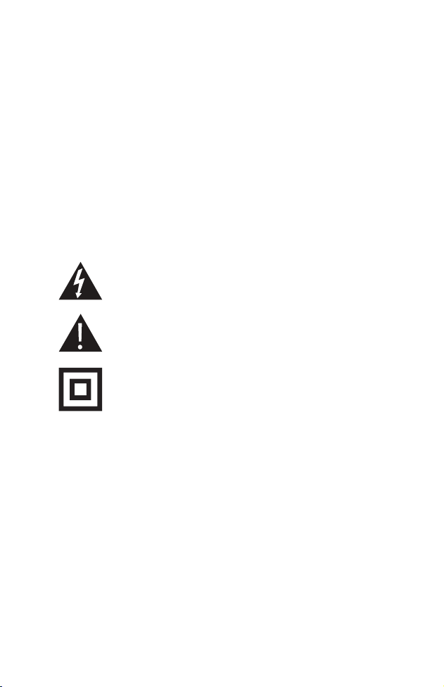
The lightning flash with arrowhead symbol within an equilateral triangle is intended to
alert the user to the presence of uninsulated “dangerous voltage” within the products
enclosure that may be of sufficient magnitude to constitute risk of electric shock to
persons.
The exclamation point within a triangle is intended to alert the user to the presence of
importance operating and maintenance {servicing) instructions in the literature
companying the product.
The equipment is a Class II or double insulated electrical appliance. It has been designed
in such a way that it does not require a safety connection to electrical earth.
I.
FCC Statement
This equipment has been tested and found to comply with the limits for a Class B digital device, pursuant to part 15 of the FCC
Rules. These limits are designed to provide reasonable protection against harmful interference in a residential installation. This
equipment generates, uses and can radiate radio frequency energy and, if not installed and used in accordance with the
instructions, may cause harmful interference to radio communications. However, there is no guarantee that interference will not
occur in a particular installation. If this equipment does cause harmful interference to radio or television reception, which can be
determined by turning the equipment off and on, the user is encouraged to try to correct the interference by one or more of the
following measures:
Reorient or relocate the receiving antenna.
Increase the separation between the equipment and receiver.
Connect the equipment into an outlet on a circuit different from that to which the receiver is connected.
Consult the dealer or an experienced radio/ TV technician for help.
This device complies with part 15 of the FCC Rules. Operation is subject to the following two conditions:
This device may not cause harmful interference.
This device must accept any interference received, including interference that may cause undesired operation.
Any changes or modifications not expressly approved by the party responsible for compliance could void the user’s authority to
operate the equipment.
This equipment complies with FCC RF radiation exposure limits set forth for an uncontrolled environment. This device and its
antenna must not be co-located or operating in conjunction with any other antenna or transmitter.
No necessary to perform SAR testing
The antennas used for this transmitter must be installed to provide a separation distance of at least 20 cm from all persons and
must not be co-located or operating in conjunction with any other antenna or transmitter.”
IC Certification (CANADA)
IC regulatory conformance
This device complies with Industry Canada license-exempt RSSs. Operation is subject to the following two conditions:
This device may not cause interference, and This device must accept any interference, including interference that may cause
undesired operation of the device.
Le présent appareil est conforme aux CNR d’Industrie Canada applicables aux appareils radio exempts de licence. L’exploitation
est autorisée aux deux conditions suivantes :
l’appareil ne doit pas produire de brouillage;
l’utilisateur de l’appareil doit accepter tout brouillage radioélectrique subi, meme si le brouillage est susceptible d’en
compromettre le fonctionnement.
CAN ICES-3(B)/NMB-3(B)
This Class B digital apparatus complies with Canadian ICES-3.
Cet appareil numérique de classe B est conforme à la norme canadien ICES-3.
RF Exposure
This equipment complies with IC radiation exposure limits set forth for an uncontrolled environment. This equipment should be
installed and operated with minimum distance of 20 cm between the radiator and your body. This transmitter must not be
co-located or operating in conjunction with any other antenna or transmitter.
Cet équipement est conforme aux limites d’ exposition aux rayonnements de la IC établies pour unenvironnement non contrôé.
Cet équipement doit être installé et fonctionner à au moins 20 cm de distance d’un radiateur ou de votre corps.
II.
This product and, if applicable, the supplied accessories are marked with
"CE" and comply therefore with the applicable harmonized European
standards listed under the Radio Equipment Directive 2014/53/EU, the
EMC Directive 2014/30/EU, the RoHs Directive 2011/65/EU.
III.
2012/19/EU (WEEE directive): Products marked with this symbol cannot
be disposed of as unsorted municipal waste in the European Union. For
proper recycling, return this product to your local supplier upon the
purchase of equivalent new equipment, or dispose of it at designated
collection points. For more information see: www.recyclethis.info.
IV.
Operating temperature: 0 - 40°C
V.
Typ:12dBm
VI.
Network Standby :
To maintain a continuous connection, this product does not have a standby mode.
(877) 626-5623 | Youngstown, OH, USA | svsound.com