
PB-2000 SB-2000
POWERED SUBWOOFERS
Subwoofer Isolation System
OWNER’S MANUAL

Thank you, and congratulations on purchasing your new
SVS SoundPath Subwoofer Isolation System!
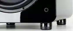
The SVS SoundPath Subwoofer Isolation System decouples and isolates the
subwoofer from the flooring, resulting in tighter and cleaner sounding bass, less
buzz/rattle in the room, and fewer complaints from adjacent neighbors in apartments
and townhouses. It’s the next best thing to sound-proofing!
The SoundPath Subwoofer Isolation System works with any brand of subwoofer
which accepts screw-in feet. Developed with extensive accelerometer and acoustic
measurements, this system features optimized durometer elastomer feet which
significantly reduce floor vibration.
Our Sound Experts in Customer Service can assist you with installing the SoundPath
Subwoofer Isolation System, so please don’t hesitate to contact Customer Service if
you need guidance.
If you have any questions about your SVS product, please contact us directly.
www.svsound.com • [email protected] • (877) 626-5623
owner’s manual v. 1.0_10252013
1

TABLE OF CONTENTS
PACKAGE CONTENTS 3
INSTALLATION 4
CABINET / BOX STYLE SUBWOOFERS
4
SVS CYLINDER SUBWOOFERS – BASE PLATE RETAINED 5
SVS CYLINDER SUBWOOFERS – BASE PLATE REMOVED 6
SPECIFICATIONS 7
SHARE YOUR THOUGHTS 7
2
PACKAGE CONTENTS
Package Contents:
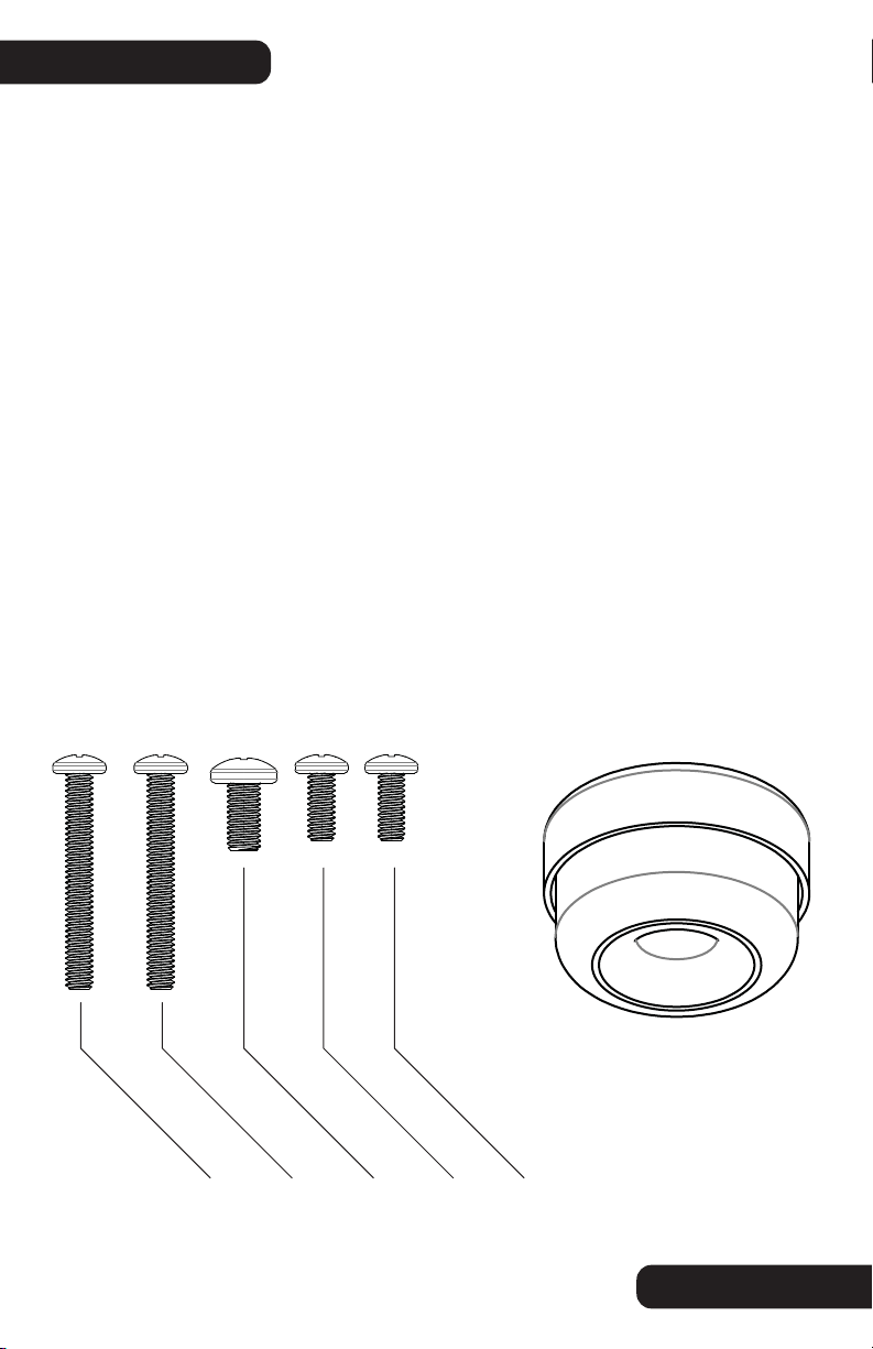
4 Foot System:
• Four (4) SoundPath Isolation Elastomer Feet with Steel Outer Shell
• Four (4) ¼-20 x 16 mm screws
• Four (4) M6 x 16 mm screws
• Four (4) M8 x 16 mm screws
• Four (4) ¼-20 x 51 mm screws (SVS PC models – baseplate removed)
• Four (4) M6 x 51 mm screws (SVS PC models – baseplate removed)
6 Foot System:
• Six (6) SoundPath Isolation Elastomer Feet with Steel Outer Shell
• Six (6) ¼-20 x 16 mm screws
• Six (6) M6 x 16 mm screws
• Six (6) M8 x 16 mm screws
• Six (6) ¼-20 x 51 mm screws (SVS PC models – baseplate removed)
• Six (6) M6 x 51 mm screws (SVS PC models – baseplate removed)
3
¼-20 x 51 mm
¼-20 x 16 mm
M6 x 51 mm
M6 x 16 mm
M8 x 16 mm
SoundPath Isolation
Elastomer Feet
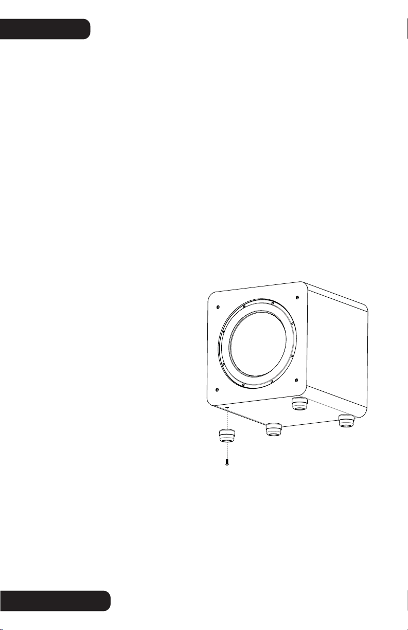
INSTALLATION CABINET / BOX STYLE SUBWOOFERS
Cabinet / Box Style Subwoofers:
1. Place padding such as a soft blanket on the flooring to protect the finish of the
subwoofer.
2. Using a helper (if needed), carefully place the subwoofer cabinet on its side or top,
resting on the blanket. Take care to avoid damaging the amplifier. Important Notice: When
moving the subwoofer, do not allow the weight of the cabinet to place an excessive lateral
(sideways) load on the feet. This may damage the feet, the threaded insert or the cabinet.
3. Unthread and remove the subwoofer's original equipment (OE) feet.
4. Gather all of the 16 mm long machine screws from the Isolation System kit. There are
three (3) thread sizes provided – ¼-20, M6 and M8.
5. Compare the OE feet machine screws to the 16 mm long Isolation System machine
screws. Select the matching/correct thread size (SVS cabinet subwoofers utilize the ¼-20
thread size).
6. Once you have selected the correct thread size, install the Isolation feet by inserting
the 16 mm long machine screw through the bottom opening of the rubber foot, through the
opening in the steel outer shell, and
into the threaded insert of the
subwoofer cabinet.
7. Make sure the machine screw is
correctly aligned and does not
cross-thread.
8. Hand-tighten snugly. Avoid
over-tightening, which might damage
the threaded insert or the cabinet.
9. Using a helper (if needed) carefully
lift the subwoofer cabinet and place it
directly down onto the installed
Isolation feet. Take care to avoid
damaging the amplifier.
Important Notice: When placing the subwoofer back into position, do not allow the weight of the cabinet to place an
excessive lateral (sideways) load on the Isolation feet. This may damage the Isolation feet, the threaded insert or the
cabinet.
Important Notice: - Do not drag the subwoofer cabinet across the flooring with the Isolation feet installed. This may
damage the Isolation feet, the threaded insert or the cabinet. If you need to move the subwoofer, always lift (use a
helper if needed) the subwoofer and then place it into the new location.
4
5
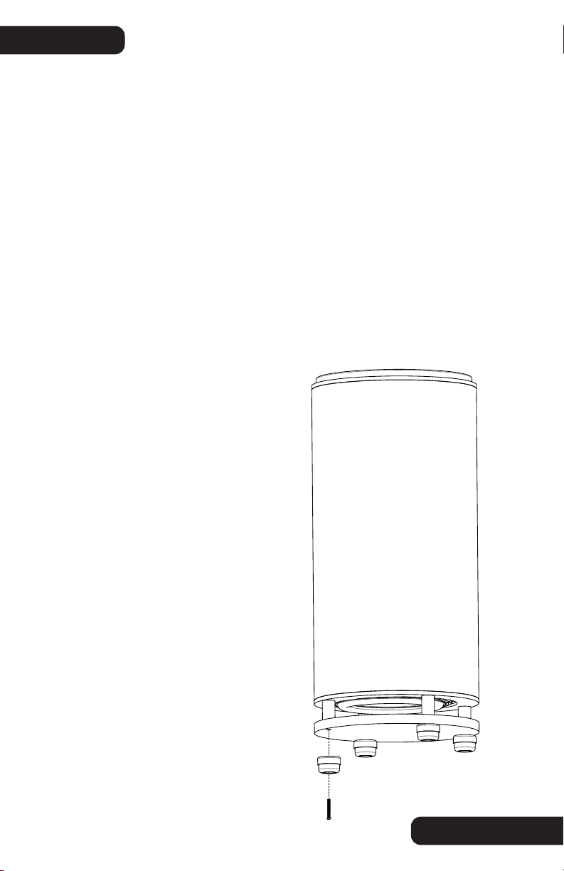
INSTALLATION SVS CYLINDER SUBWOOFERS
SVS Cylinder Subwoofers – Base Plate Retained:
1. Using a helper as needed, lay the cylinder subwoofer sideways on a stable surface.
Take care to avoid damaging the amplifier.
2. Peel off the original equipment (OE) rubber disc feet.
3. Only remove one (1) OE machine screw at a time. This will prevent the base plate
from dislodging. Important Notice: - If you are using a powered bit driver to remove and/or
install the machine screws, avoid excessive
downward pressure on the screw, as that
may dislodge the t-nut mounted to the
backside of the woofer end-cap.
4. Install the Isolation foot by inserting
the OE machine screw through the bottom
opening of the rubber foot, through the
opening in the steel outer shell, through the
base plate, through the dowel (re-aligning
the dowel as necessary) and into the t-nut
on the backside of the woofer end-cap.
5. Make sure the machine screw is
correctly aligned and does not cross-thread.
6. Tighten the OE machine screw avoiding
excessive downward pressure. Once the
screw fully tightens and starts to pull
against the end-cap t-nut, tighten securely
using hand-pressure.
7. Using a helper (if needed), carefully
stand the cylinder subwoofer back onto the
installed Isolation feet. Take care to avoid
damaging the amplifier.
SVS Cylinder Subwoofers:
There are two options for installing the Isolation System on SVS cylinder subwoofers - base
plate retained or base plate removed. Retaining the base plate is recommended in
applications which have very high pile carpeting, in order to avoid woofer interference at
high playback levels. Aside from that exception, there is no performance difference
between the two options, so choose whichever option you personally prefer.
Important Notice: - Do not drag the subwoofer base
plate across the flooring with the Isolation feet
installed. This may damage the Isolation feet or the
base plate. If you need to move the subwoofer, always
lift (use a helper if needed) the subwoofer and then
place it into the new location.
6
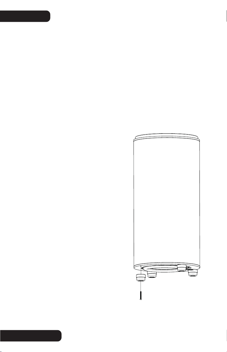
INSTALLATION SVS CYLINDER SUBWOOFERS
SVS Cylinder Subwoofers – Base Plate Removed:
1. Using a helper as needed, lay the cylinder subwoofer sideways on a stable surface.
Take care to avoid damaging the amplifier.
2. Peel off the original equipment (OE) rubber disc feet.
3. Remove the OE machine screws. Support the base plate as needed to prevent it from
inadvertently dislodging while removing the screws. Important Notice: - If you are using a
powered bit driver to remove and/or install the machine screws, avoid excessive downward
pressure on the screw, as that may dislodge the t-nut mounted to the backside of the
woofer end-cap
4. Remove the base plate and the dowels and set aside.
5. Gather all of the 51 mm long machine screws from the Isolation System kit. There are
two (2) thread sizes provided – ¼-20 and M6.
6. Compare the OE feet machine screws to the
Isolation System 51 mm long machine screws
and select the matching/correct thread size.
7. Install each Isolation foot by inserting the
51 mm long machine screw through the bottom
opening of the rubber foot, through the opening
in the steel outer shell and into the t-nut on the
backside of the woofer end-cap.
8. Make sure the machine screw is correctly
aligned and does not cross-thread.
9. Tighten the machine screw avoiding
excessive downward pressure. Once the screw
fully tightens and starts to pull against the
end-cap t-nut, tighten securely using hand-
pressure.
10. Using a helper (if needed) carefully stand
the cylinder subwoofer back onto the installed
Isolation feet. Take care to avoid damaging the
amplifier.
Important Notice: - Do not drag the subwoofer base
plate across the flooring with the Isolation feet
installed. This may damage the Isolation feet or the
base plate. If you need to move the subwoofer, always
lift (use a helper if needed) the subwoofer and then
place it into the new location.

SPECIFICATIONS
7
Materials Of Construction:
• Durable Anodized Steel Outer Shell
• Elastomer Foot with Optimized Durometer
• Steel Machine Screws
SoundPath Isolation Feet Dimensions:
• Overall Height: 40 mm
• Shell Diameter: 58 mm
• Foot Diameter: 53 mm
• Screw Engagement Depth: 9 mm (applies to 16 mm length screws)
SHARE YOUR THOUGHTS
At SVS, we strive to deliver products that surpass every expectation and provide unbeat-
able value. After you have had an opportunity to install and audition the impact of the
SoundPath Subwoofer Isolation System on your subwoofer, please share your comments for
our team and other customers to see.
Write a review at svsound.com
Post at facebook.com/SVSound
Tweet @SVSSoundExperts

................................................................................................................................................
................................................................................................................................................
................................................................................................................................................
................................................................................................................................................
................................................................................................................................................
................................................................................................................................................
................................................................................................................................................
................................................................................................................................................
................................................................................................................................................
................................................................................................................................................
................................................................................................................................................
................................................................................................................................................
................................................................................................................................................
................................................................................................................................................
................................................................................................................................................
................................................................................................................................................
................................................................................................................................................
................................................................................................................................................
................................................................................................................................................
................................................................................................................................................
................................................................................................................................................
................................................................................................................................................
................................................................................................................................................
................................................................................................................................................
................................................................................................................................................
................................................................................................................................................
................................................................................................................................................
................................................................................................................................................
................................................................................................................................................
................................................................................................................................................
................................................................................................................................................
................................................................................................................................................
NOTES
8

SVS
6420 Belmont Ave.
Girard, Ohio 44420
United States
(877) 626-5623
www.svsound.com