21
Panel type
Power supply voltage
AC100~240V 50/60Hz or DC12-24V
85% ~ 110% of rated supply voltage
Power consumption
About at AC100 ~ 240V 5VA and DC12~24V 3W
Display mode
7-segment negative LED liquid crystal display, PV White SV green light indicator
orange light
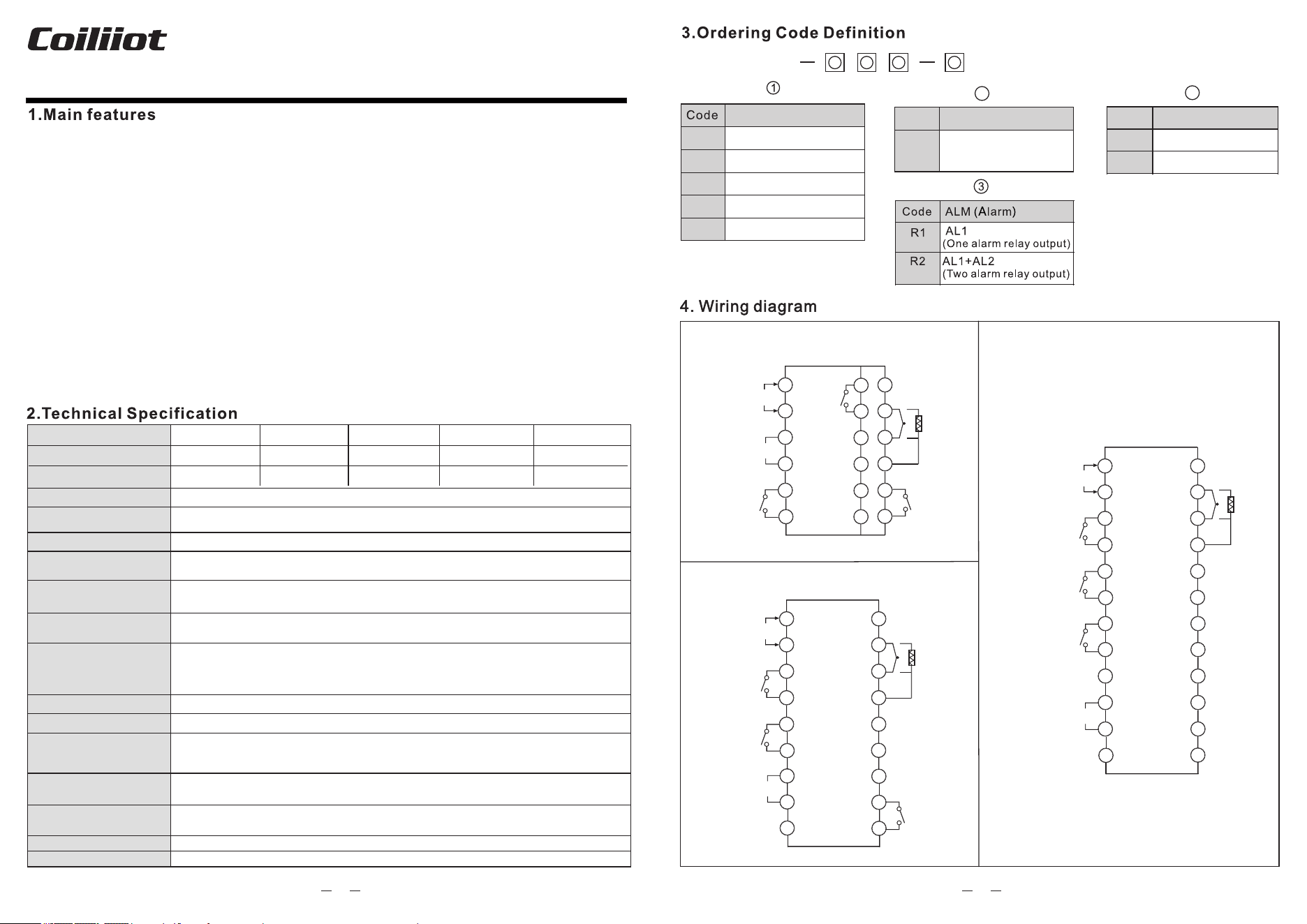
Input specifications and
measuring range
TC Thermocouple: K (-50~ 1300°C), E (0~800°C), J (0~1000°C), N (0~1300°C)
RTD Thermal resistance: Pt100 (-200~ 600°C)
The number of decimal
places
0(None) , 0.0(1 decimal point) Set by dp parameter
Accuracy is at grade 0.25 when thermal resistance and thermocouples are used as
inputs, with cold-end compensation provided by copper resistance or the freezing
point.Accuracy is 0.25% FS ± 2.0°C when the input is from a thermocouple with cold-
end compensation handled by the internal components of the instrument.
Sampling period
80ms (when digital filter parameter INF = 0) , display response time ≤0.5 seconds
Control mode
ON/OFF bit adjustment, PID + FUZZY artificial intelligence adjustment algorithm
Contact output
IEC61000-4-4(electrical fast transient pulse group) , ± 4KV/5KHz;
IEC61000-4-5(surge) , 4KV
Isolation withstand
voltage
The power supply, relay contacts and signal terminals are ≥2300VDC each other,
and the isolated weak current signal terminals are ≥600VDC each other
AiFUZZY-806
48×48
72×72
96×96 48×96 96×48
G
D A
E
F
45 ×45
+0.6
+0. 6
68 ×68
+0. 6
+0. 6
92 ×92
+0. 6
+0. 6
45 ×92
+0.6
+0.6
92 ×45
+0. 6
+0. 6
Panel size mm (width × height)
Hole size mm (width × height)
Range of allowable voltage
variation
Measurement accuracy
Electromagnetic
compatibility
Dimens ions (width × height)
(vertical)
(horizontal)
48×48mm
72×72mm
96×96mm
48×96mm
96×48mm
G
D
A
E
F
1
1
1
1
1
3
4
5
6
7
8
1
2 3
4
2
AiFUZZY-806
1
Blank
AC100~240V
D
DC12~24V
4
● AiFUZZY-806-G
● AiFUZZY-806-A,E,F
● AiFUZZY-806-D
Relay+SSR Dual type output
Operating Ambient
Storage temperature
Temperature:-10~+60°C,Humidity: 25~85%
Temperature:-25~+70°C,Humidity: 25~85%
Relay:5A/250VAC Resistive Load, 5A/30VDC resistive load
SSR:12VDC/50mA(Drive external solid state relay)
6
6
6
9
7
8
9
1
1
1
1
1
1
1
1
1
1
1
1
1
1
1
0
0
1
2
3
4
5
6
7
3
0
1
2
4
6
1
2
8
0
1
2
3
4
9
5
1
1
1
2
2
2
2
2
1
1
1
1
7
1
2
2
8
2
3
3
9
3
4
4
4
5
5
5
7
8
POWER:
POWER:
POWER:
AL1
250AC
5A max
AL1
250AC
5A max
AL1
250AC
5A max
Relay OUT
250VAC
5A max
Relay OUT
250VAC
5A max
Relay OUT
250VAC
5A max
A
A
A
B
B
B
B
B
B
SSR OUT
12VDC
50mA max
SSR OUT
12VDC
50mA max
SSR OUT
12VDC
50mA max
Code
Power supply
Code
OUT (control output)
Q5
Relay+SSR
(Dual type output)
7
1
8
1
● High-value, super-large display with new, high-brightness LED segments, designed
to enhance visibility from all angles and at long distances.
● Economically designed for easy operation and practical functionality, specially tailored for
temperature control.
● Supports common TC and RTD input types, selectable via software parameters.
● Achieves measurement accuracy at the 0.25% level. Measurement errors caused by temperature
drift and time drift are minimized through digital correction and self-calibration technologies.
● Features an advanced "FUZZY+PID" AI intelligent control mode, preventing overshoot and
including auto-tuning (AT) and self-adaptation functions.
● Provides up to two-way alarm outputs and supports various alarm methods.
● Allows selection between °C and °F for temperature units via software parameters.
● High-efficiency and high-reliability switching power supply, compatible with a global universal
voltage range of AC100~240V or DC12~24V.
● The anti-interference performance meets the requirements for electromagnetic compatibility
(EMC) in harsh industrial conditions.
● PID control output features dual-type outputs of Relay and SSR; the output from either Relay or
SSR can be selected through system parameters.
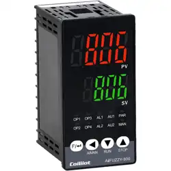
LED display economical intelligent temperature controller
AL2
250AC
5A max
AL2
250AC
5A max
AL2
250AC
5A max
+
-
+
-
+
-
+
-
+
-
+
-
TC
TC
TC
RTD
RTD
RTD
PV
SV
1
2
6
3
7
4
5
OP3
OP4
AL1
AU1
AL2
AU2
PAR MAN
OP1 OP2
F/
STOP
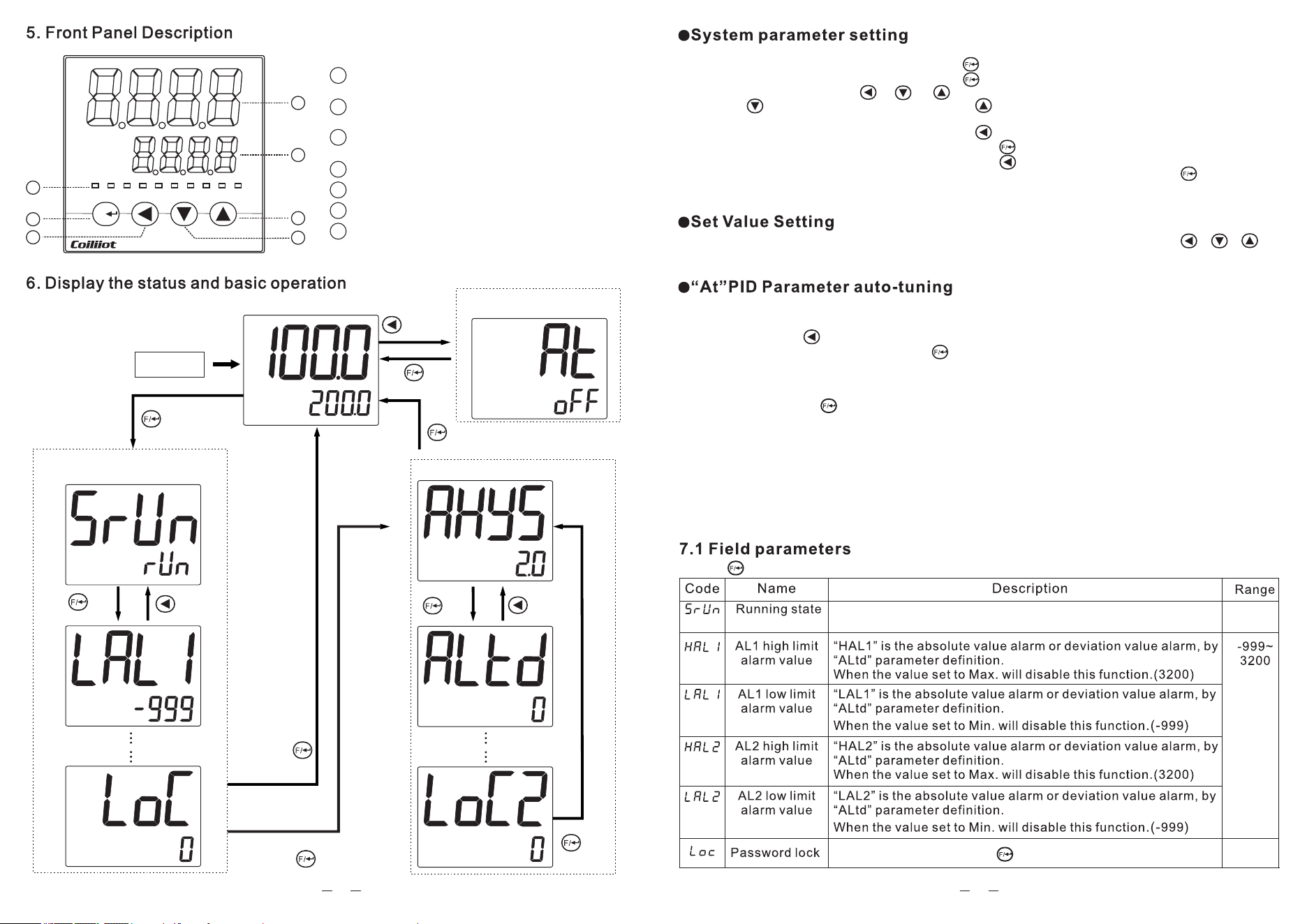
PV display window (displays measurements,
parameter names, and so on)
1
SV display window (displays given
values, parameter values, and so on)
2
Setup key: For accessing parameter table
and conforming parameter modification.
3
Data shift key, start auto tuning.
4
Data decrease key, and also run switch.
5
Data increase key, and also stop key.
6
7
AiFUZZY-800
Power-on
Site parameters
43
System parameters
Set Loc = 800, then
press the key
If LOC ≠800,
press the
key
Key 2 sec
Key 2 sec
Key 2 sec
Key 2 sec
Omit the
description
Omit the
description
Setting at = On
will start self-tuning
Basic display status
Key 2 sec
The first parameter
The second parameter
The first parameter
The second parameter
Key
Key
Key
Key
Press 2 seconds to enter the site parameter settings
The last parameter
The last parameter
7.Parameter list and function
Output indicators:OUT,AL1,AL2 indicators
In the basic display state, press and hold the key for 2 seconds to enter the field parameters
setting mode. Set LOC to 800, then press the button to confirm and proceed to the system
parameter settings.Use the , , and C keys to directly modify the parameter values.
Press the key to decrease the data and the key to increase it. When modifying, the value
of the decimal point will flash like a cursor. Press and hold a key to quickly adjust the value, which
will automatically speed up over time.Press the key to move the cursor to a different data loca-
tion, making the operation more efficient.Press the key to save the modified parameter values
and display the next parameter. Press and hold the key for 2 seconds to return to the previous
parameter. To exit the pa-rameter setting mode immediately, press and hold the key for 2
seconds.
In the basic display state, you can directly modify the given value by pressing the , ,
buttons.
To enable optimal PID control parameters using the auto-tuning feature, follow these steps for
precise control:
Press and hold the button for 2 seconds until the "At" parameter appears.Set the "At" param-
eter from "OFF" to "ON," then press the button to confirm. The instrument will begin the auto
-tuning process. During this, the word "At" will flash on the basic display state.After two oscillation
cycles of ON-OFF control, the instrument will automatically calculate the PID parameters.
If you wish to cancel the auto-tuning before completion.Change the "At" parameter from "ON" to
"OFF," then press the button to confirm.
The tuning parameter values obtained may vary. To perform the auto-tuning function, first set the
given value to the most commonly used or a median value. If the system involves a well-insulated
furnace, set the given value to the maximum typically used by the system before starting the auto
-tuning.The initial results from auto-tuning may not be optimal. It often requires a period (usually
the same duration as the auto-tuning control) to achieve the best results.Do not operate the cont-
roller or interrupt the power supply during the auto-tuning process.
Set LOC = 800, then press key to input system parameters.
r un t h e c o n t r o l s t a t e .
St o p : S t o p S t a t e , SV w i n d ow s h o w s f l a s h i n g d i s p l a y“ S t o P ”
( Ex-factory
value run)
( ex -fac tory
valu e,
uppe r
li mit: 3200
lo wer limit :
-9 99)
( Ex-factory value 2.0)
( Ex-factory
value 1)
( Ex-factory value
FPld)
( Ex-factory value
onr)
( Ex-factory value
25. 0)
( Ex-factory value
200)
( Ex-factory value
50.0)
0~3200
( Ex-factory value
relay output 15.0
SSR output 2.0)
( Ex-factory value
2.0)
( Ex-factory
value K)
( Ex-factory
value 0)
( Ex-factory
value 0)
( Ex-factory
value 2)
( Ex-factory
value °C)
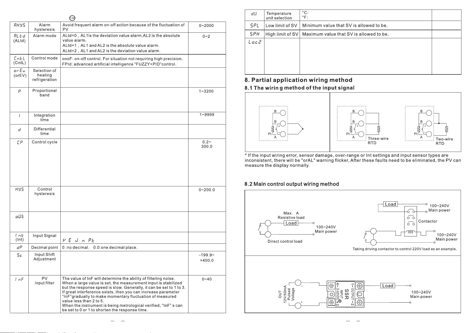
Selection ofinput Types for thermocouples or RTD
, , , ,
( Pt100)
already know the
correct values.
nceled when l=0.
anceled when d=0.
Set Loc = 800, then press the key to enter the following system parameters
65
( Default value 2.0)
( Default value1)
( Default value
FPld)
( Default value
onr)
( Default value
25. 0)
( Default value
200)
( Default value
50.0)
0~3200
( Default value
relay output 15.0
SSR output 2.0)
(OUT)
( Default value
2.0)
( Default value K)
( Default value
rELy)
Control output
( Default value 0)
( Default value 0)
( Default value 2)
( Default value
°C)
Degrees celsius
Degrees fahrenheit
Selection ofinput Types for thermocouples or RTD
rELy:Relay contact signal output.
SSR:Drive solid-state relay output.
(When OUT is set to SSR output, the output of the OUT relay can be
used as the AL2 alarm output, so that there are two alarm outputs.)
, , , ,
( Pt100)
LOC2=0: Unlocking, no locking function.
LOC2=1: AT self-tuning parameter cannot be set.
LOC2=2: Field parameters cannot be set.
LOC2=3: SV setting value cannot be set
LOC2 =4: AT self-tuning, The current field parameter and
SV setting values can not be set
0~4
Password lock2
●Thermocouple Input
●RTD Input
●Relay output (OUT port installs R module)
●12V pulse voltage output drive SSR(OUT port installed Q module)
( Default value
0)
-999~3200
(Default value -999)
-999~3200
(Default value 999)
RTD
Input
RTD
Input
TC
Input
OUT
OUT
7.2 System parameter
5
onr: Reverse Acting - An increase in the measured variable results
in a decrease in the output. This is typical in heating control systems.
ond: Direct Acting - An increase in the measured variable leads to an
increase in the output. This is common in refrigeration control systems.
The integration time for FPID adjustment is measured in
seconds. The integral action is canceled when I=0
CP reflects the instrument operator's ability to adjust the speed.
The magnitude of CP affects the control accuracy.For control
cycles using SSR or SCR outputs, a shorter duration is preferable,
typically ranging from 0.5 to 3.0 seconds. For relay switch outputs,
the typical range is between 15 to 40 seconds.When the output
relay switches, CP is limited to 3 seconds. During self-tuning (At),
CP will be automatically set to an appropriate value, considering
both control accuracy and mechanical switch life.When the control
mode (CntL) is set to onoF, the action of CP acts either as an output
disconnect or as a power-on output with an ON Delay time.
The differential time for FPID adjustment is measured in
tenthsof a second (0.1 sec), and the differential effect is
canceled when d=0.
HYS is used in ON-OFF control to prevent the frequent toggling
of relay.In a reverse acting (heating) system: the output turns
off when PV > SV, and turns on when PV < SV - HYS.In a direct
acting (cooling) system: the output turns off when PV < SV, and
turns on when PV > SV + HYS.
SC is used to adjust the input to compensate for errors caused by
the transducer, input signal, or automatic cold junction compens-
ation of thermocouples. PV after compensation = PV before com-
pensation + SC.It is generally set to 0. Incorrect settings can lead
to measurement inaccuracies.
Proportional band in FPId control is expressed in the same units
as the PV, rather than as a percentage of the measurement
range.Generally, optimal P, I, D, and CP can be obtained
through auto-tuning.These parameters can also be manually
input if the correct values are already known.
8
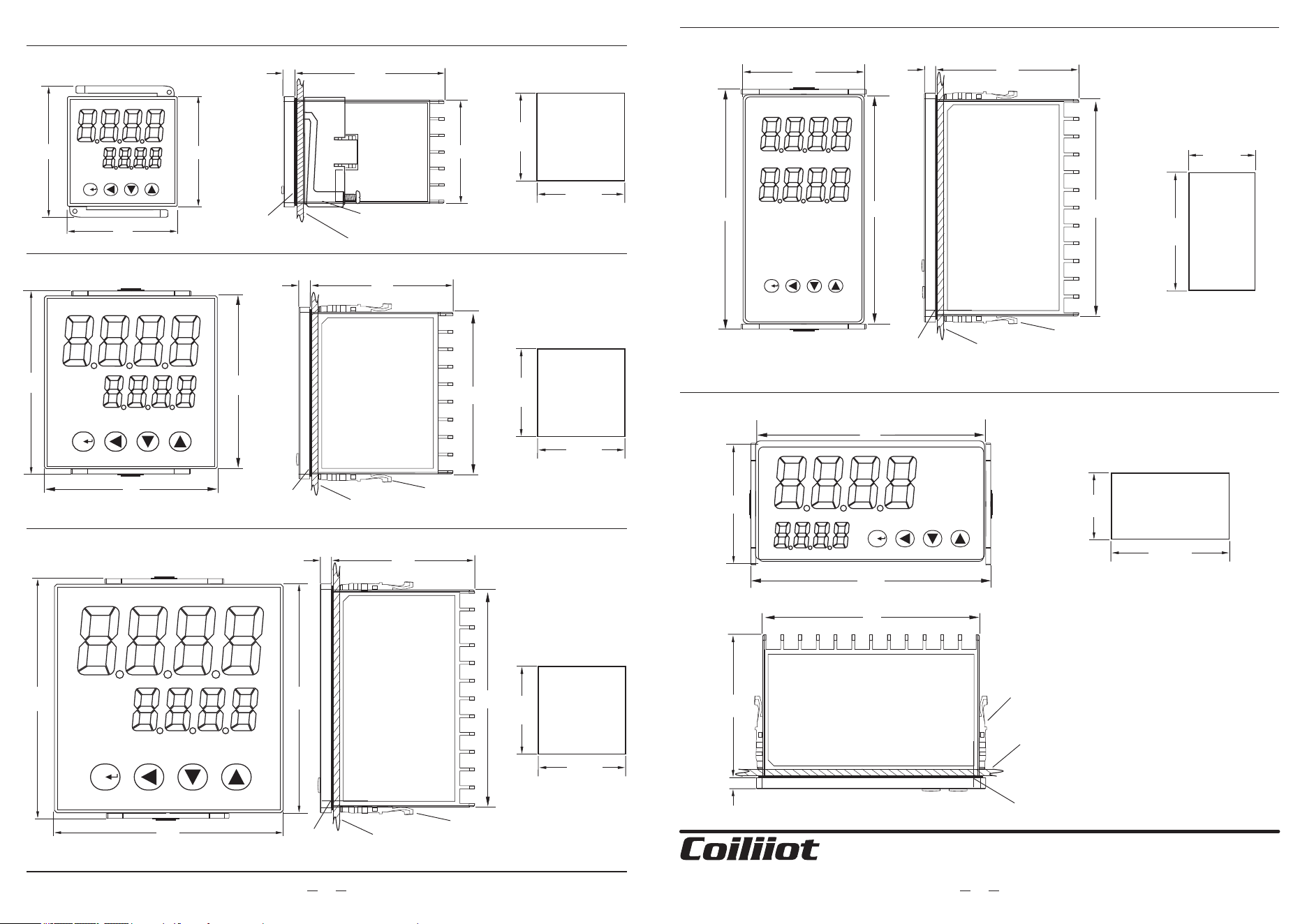
9.Dimensions (in mm) and installation instructions
45
68
92
+0.6
+0.6
+0.6
-0
-0
-0
45
68
92
+0.6
+0.6
+0.6
-0
-0
-0
78
100
96
96
72
68
92
72
60
4.7
60
4.7
48
58
48
Panel thickness 1~5mm
Panel thickness 1~5mm
Panel thickness 1~5mm
Mounting Adapter(Accessory)
Mounting Adapter(Accessory)
Mounting Adapter(Accessory)
Waterproof Packing
(Accessory)
Waterproof Packing
(Accessory)
Waterproof Packing
(Accessory)
65.2
4.7
45
● AiFUZZY-806-G
● AiFUZZY-806-D
● AiFUZZY-806-A
Single install
opening size
Single install
opening size
Single install
opening size
F/
F/
F/
STOP
STOP
7
48
100 96
96
Panel thickness 1~5mm
Panel thickness 1~5mm
Mounting Adapter(Accessory)
Mounting Adapter(Accessory)
Waterproof Packing
(Accessory)
Waterproof Packing
(Accessory)
45
+0.6
-0
92
+0.6
-0
92
100
60
4.7
48
92
60
4.7
45
+0.6
-0
92
+0.6
-0
●
● AiFUZZY-806-F
Single install
opening size
Single install
opening size
F/
F/
STOP
STOP
AiFUZZY-806-E
https://www.coiliiot.com E-mail: info@coiliiot.com
Made in China