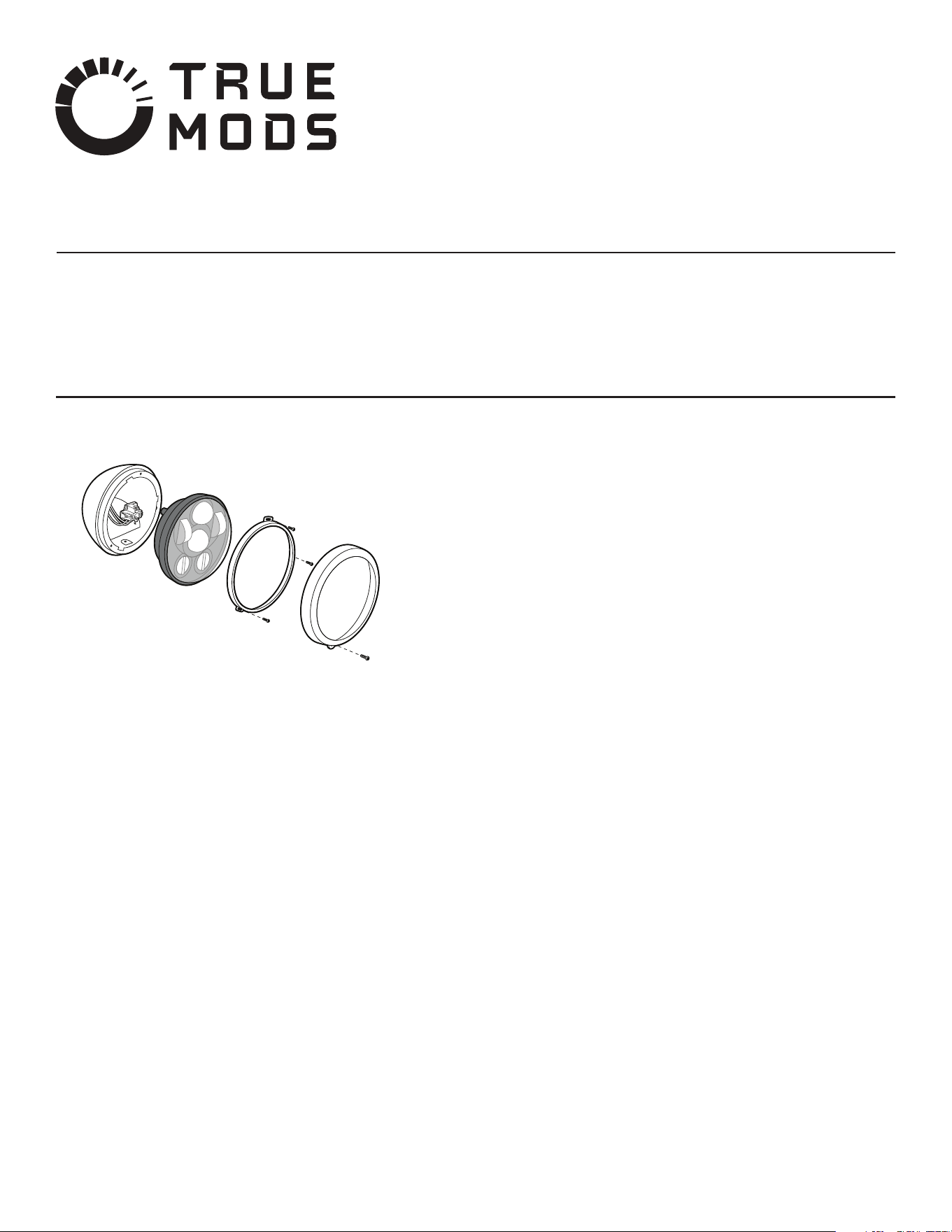
Locate the headlight trim ring screw on the underside of the headlight trim ring.
NOTE: Some motorcycle has the headlight secured with just the trim ring while
others will have an internal retaining ring underneath the trim ring. Be sure to keep
some pressure on the headlight while you remove the trim ring to prevent it from
falling forward. Proceed to Step 1.5 if your motorcycle does not have an internal
retaining ring securing the headlight.
Loosen screw to remove the trim ring and set aside being careful not to damage
the nish.
NOTE: Many trim ring can be taken o simply by pulling it away from the
headlight once its fastener has been removed. Some trim ring requires one to turn
the screw tab on the underside of the trim ring from the 6 o’clock position to the
4 o’clock position for removal.
With the trim ring removed, the retaining ring and its three fasteners will now be
accessible.
TIP: Always apply gentle pressure to the headlight while removing the retaining
ring to prevent it from falling forward. If there is a fastener located towards the
top of the retaining ring, consider removing it last as it supports the headlight in
place for the meantime.
Remove the retaining ring and set it aside with the three fasteners.
Carefully pull the headlight out of the headlight housing.
NOTE: There may be a metal retaining ring in the headlight housing which is not
fastened. It may fall out. When reinstalling the headlight, make sure the external
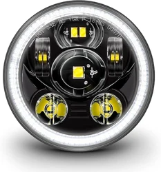
5.75˝ LED Headlight for Harley Davidson Motorcycle
•
www.truemods.com
US Toll Free: 1-855-533-6654
International: 1-909-212-0993
Fax: (909) 575-6722
E-mail: [email protected]
True Mods © 2012-2021 All Rights Reserved
procedures are followed. Always turn the key o and disconnect the battery before working on
vehicle electronics, neglecting to do so may result in bodily harm and damage to sensitive
electronic components. Never cut or splice a wire without rst consulting a vehicle specic
manual and using a digital multimeter (DMM) to verify the identity and purpose of the wire.
This product contains strobe light(s), halogen light(s), high-intensity LEDs, or a combination of
these components. Do not look directly into the lights. Momentary blindness and/or injury to the
eyes could result.
IMPORTANT: READ CAREFULLY BEFORE ASSEMBLY AND USE.
•
•
•
Installer of this product must have a good understanding of automotive electronics, systems, and
procedures.
WARNING! Whether it is replacing the headlight low beam, headlight high beam, or fog lights,
always refer to the vehicle’s owner’s manual for detailed instruction on how such lights can be
replaced. The instructions listed in this guide serves as a general reference and the steps detailed
may not apply to your specic vehicle’s make and model. Seek professional assistance when in
doubt.
WARNING! When working with electricity make sure all relevant safety
Manual ID: PIM-00000171-V002
Installation:
Step 1: Remove the Headlight
TIP: Covering your front fender with a towel to
protect the nish from being damaged is always a good idea.
1.1
1.2
1.3
1.4
1.5
tabs line up with the holes in the headlight housing and that the internal keyway is
located at the 3 o'clock position. This is essential for correct headlight alignment.
Depress the two tabs on the side of the headlight harness connector and remove
the plug.
Remove stock headlight.
Plug the new light into the factory harness.
OPTIONAL: Models with Halo Function Only
Carefully insert the new headlight into the headlight housing making sure the tab
on the backside of the headlight aligns with the keyway in the retaining ring.
Make sure the orientation of the light is the same as shown in the installation
diagram.
NOTE: Correctly seating the headlight may be dicult due to the extra wiring
and plug from the new LED light. When installing the new light always make sure
no wires are pinched and that the light is fully seated before attempting to install
the headlight bezel and trim ring.
Proceed with re-installing any bezel and trim ring which were removed in the
previous steps. Be sure to apply constant pressure to the headlight unit to
prevent it from falling forward.
Test the headlight for proper operation.
Enjoy!
Step 2: Install the New Headlight
TIP: At this point it would be a good idea to temporarily plug in the new headlight
and test it for correct operation.
Input Voltage 10 - 30V DC
Input Current @12V DC:
Low Beam 1.5 A
High Beam: 2.0 A
Method 1 - Power Halo ON/OFF with Low Beam - Connect the RED and
YELLOW wires' bullet connectors together. Make sure the silicone insulator
covers the terminals completely.
Method 2 - Power Halo ON/OFF with Other Source - Supply power to the RED
wire (power input wire for halo) via a source of choice, such as an on/of
switch, position lamp wire, tip lamp wire, etc. Make sure the silicone insulator
covers the terminals completely.
Specications:
1.6
1.7
2.1
2.2
2.3
2.4
2.5
2.6
-
-