Page 1
LZO8*1H LZO8*2H LZO8*3H LZOD*1H
1000003484 (Rev. F - 03/25)
Model LZO8L
INSTALLATION & USE MANUAL
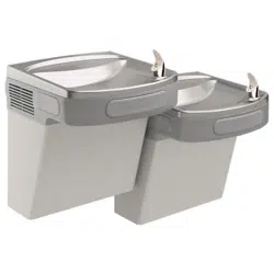
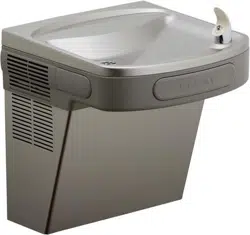
LZO™ Series Sensor-Operated Water Coolers
WARNING: Cancer and Reproductive Harm - www.P65Warnings.ca.gov
ADVERTENCIA: Cáncer y daño reproductivo - www.P65Warnings.ca.gov
AVERTISSEMENT: Cancer et eets néfastes sur la reproduction - www.P65Warnings.ca.gov
Patent zurn-elkay.com/patents
Page 2
LZO8*1H LZO8*2H LZO8*3H LZOD*1H
1000003484 (Rev. F - 03/25)
18
14
15
22
6
16
19
17
7
2
12
20
1
21
18
5
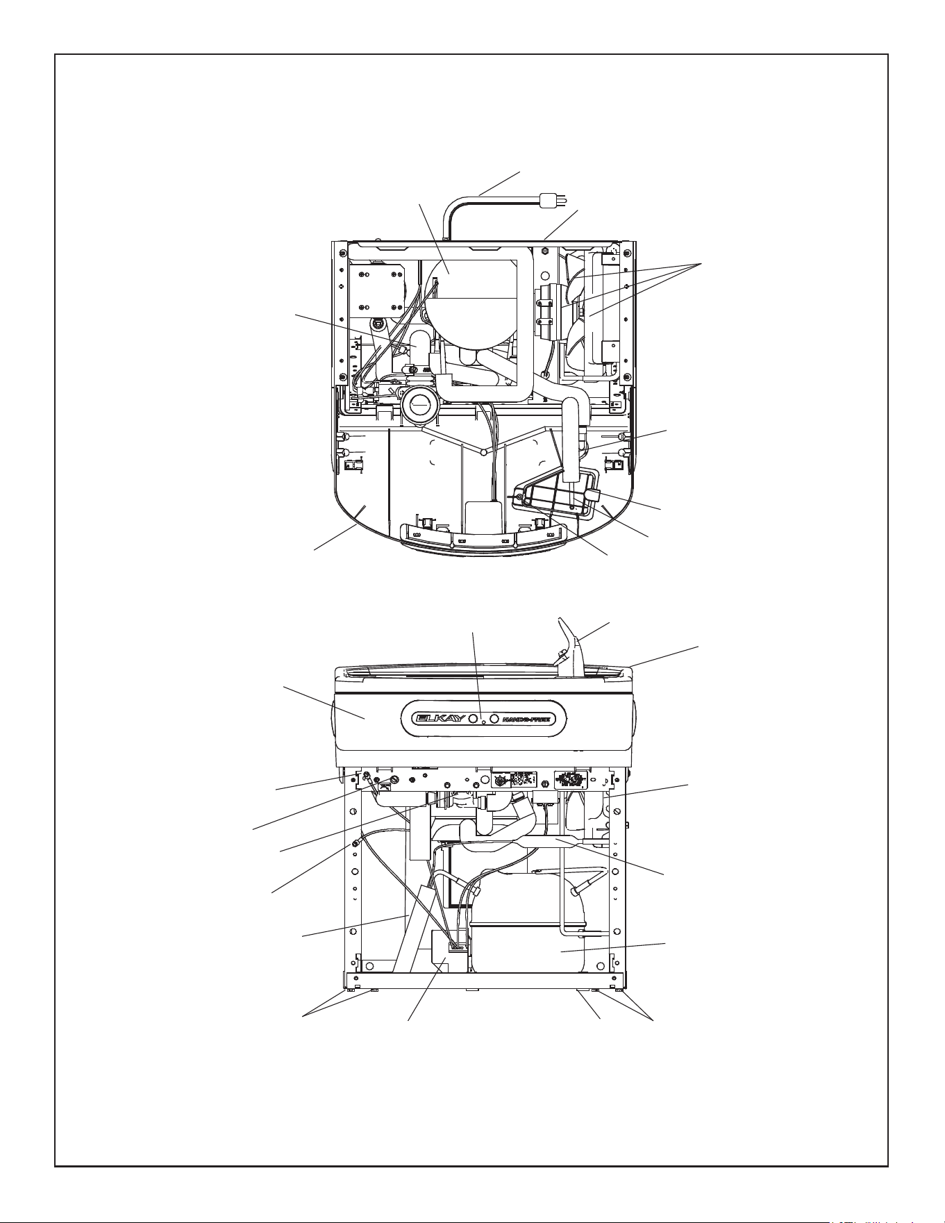
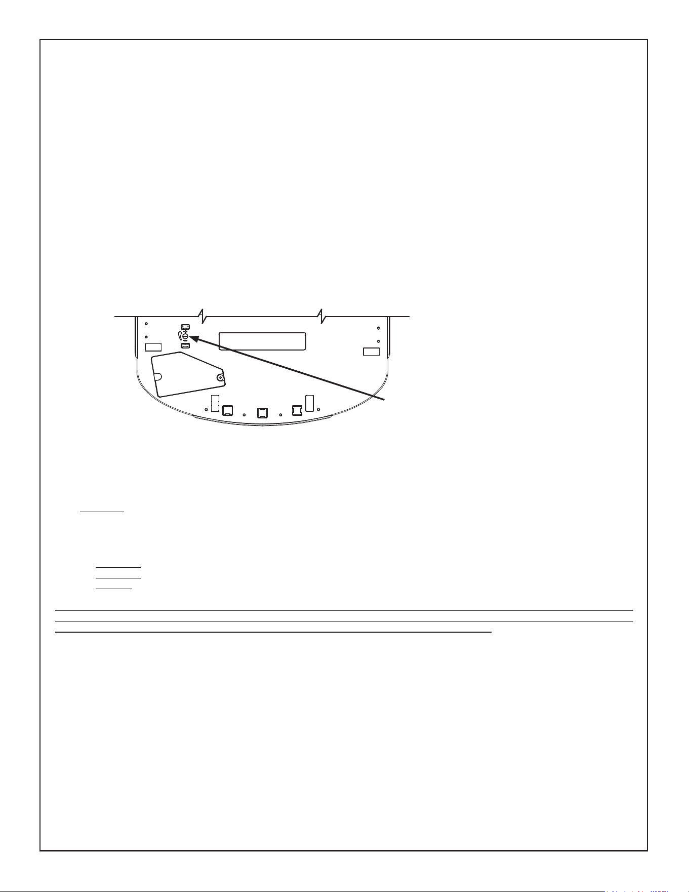
FIG. 1
Uses HFC-134A refrigerant
Note: Danger! Electrical shock hazard. Disconnect power before servicing unit.
See Fig. 3
See Fig. 4
Sensor Eye Adjustment screw
8
18
18
18
9
4
3
Page 3
LZO8*1H LZO8*2H LZO8*3H LZOD*1H
1000003484 (Rev. F - 03/25)
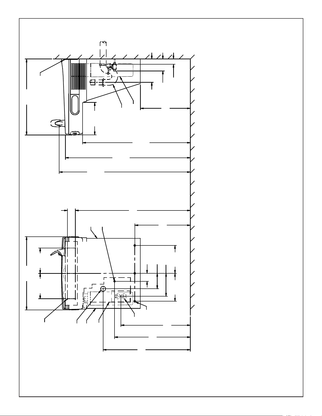
FIG. 2
A
F
E
B
E
O
9/32"
7mm
(6)
21 7/8"
556mm
17 7/16"
443mm
19"
483mm
2"
51mm
3 7/8"
98mm
7"
178mm
7"
178mm
13 15/16"
354mm
28 13/16"
732mm
2"
51mm
6 3/8"
162mm
6 3/8"
162mm
18 3/8"
467mm
‰
D
C
12 1/2"
318mm
3"
77mm
2"
51mm
27"
686mm
ADA
REQUIREMENT
31 5/16"
796mm
RIM
HEIGHT
32 7/8"
835mm
ORIFICE
HEIGHT
HANGER BRACKET
19"
484mm
FILTER
FILTER
5 3/4"
146mm
5 7/8"
150mm
8 1/16"
205mm
FINISHED FLOOR
REDUCE HEIGHT BY 3 INCHES FOR INSTALLATION OF CHILDREN’S ADA COOLER
LEGEND/LEYENDA/LÉGENDE
A = RECOMMENDED WATER SUPPLY LOCATION 3/8” O.D. UNPLATED COPPER TUBE CONNECT STUB WITH SHUT OFF (BY OTHERS) 3” IN. (76mm) MAXIMUM OUT FROM WALL
MAXIMUM WATER SUPPLY PRESSURE: 105 PSI (0.73 MPa)
La UBICACION 3/8 O RECOMENDADA de ABASTECIMIENTO DE AGUA. D. El TUBO del COBRE de UNPLATED CONECTA TALONARIO CON APAGO (POR OTROS) 3 en. (76 Mm) el MAXIMO FUERA DE PARED
PRESIÓN MÁXIMA DE SUMINISTRO DE AGUA: 105 PSI (0.73 MPa)
L’O.D de 3/8 d’EMPLACEMENT DE PROVISION D’EAU RECOMMANDE. LE TUBE DE CUIVRE DE UNPLATED CONNECTE STUB AVEC ETEINT (PAR LES AUTRES) 3 dans. (76 mm) le MAXIMUM HORS DU MUR
PRESSION MAXIMALE D’ALIMENTATION EN EAU: 105 PSI (0.73 MPa)
B = RECOMMENDED LOCATION FOR WASTE OUTLET 1-1/4” O.D. DRAIN STUB 2” OUT FROM WALL
UBICACIÓN RECOMENDADA PARA EL DRENAJE DE SALIDA DE AGUA, DE 1¼” DE DIÁMETRO. El TALONARIO 2 FUERA DE PARED
EMPLACEMENT RECOMMANDÉ POUR LE DRAIN DE D.E. 1-1/4” DE SORTIE D’EAU. STUB 2 HORS DU MUR
C = 1-1/4” TRAP NOT FURNISHED
PURGADOR DE 1¼ NO PROPORCIONADO
SIPHON 1-1/4 NON FOURNI
D = ELECTRICAL SUPPLY (3) WIRE RECESSED BOX
CAJA RECESIVA DE ALAMBRES (3) DE SUMINISTRO ELÉCTRICO
BOÎTE ENCASTRÉE D’ALIMENTATION ÉLECTRIQUE (3) FILS
E = INSURE PROPER VENTILATION BY MAINTAINING 6” (152 mm) (MIN.) CLEARANCE FROM CABINET LOUVERS TO WALL.
ASEGURE UNA VENTILACIÓN ADECUADA MANTENIENDO UN ESPACIO E 6” (152 mm) (MÍN.) DE HOLGURA ENTRE LA REJILLA DE VENTILACIÓN DEL MUEBLE Y LA PARED
ASSUREZ-VOUS UNE BONNE VENTILATION EN GARDANT 6” (152 mm) (MIN.) ENTRE LES ÉVENTS DE L’ENCEINTE ET LE MUR.
F = 7/16” BOLT HOLES FOR FASTENING UNIT TO WALL
AGUJEROS DE LAS TUERCAS DE 7/16 PARA SUJETAR LA UNIDAD A LA PARED
TROUS D’ÉCROUS 7/16 POUR FIXER L’APPAREIL AU MUR
**NEW INSTALLATIONS MUST USE GROUND FAULT CIRCUIT INTERRUPTERS (GFCI)
**LAS NUEVAS INSTALACIONES DEBEN UTILIZAR LOS INTERRUPTORES DE CIRCUITO DE TIERRA DE LA AVERÍA (GFCI)
**LES NOUVELLES INSTALLATIONS DOIVENT EMPLOYER LES INTERRUPTEURS DE CIRCUIT MOULUS DE DÉFAUT (GFCI)
Page 4
LZO8*1H LZO8*2H LZO8*3H LZOD*1H
1000003484 (Rev. F - 03/25)
HANGER BRACKETS & TRAP
INSTALLATION
1) Remove hanger bracket fastened to back of cooler by removing one (1) screw.
2) Mount the hanger bracket as shown in Fig. 2.
NOTE: Hanger Bracket MUST be supported securely. Add xture support carrier if wall will not provide adequate support. Anchor hanger securely
to wall using all six (6) 1/4 in. dia. mounting holes.
INSTALLATION OF COOLER
3) Hang the cooler on the hanger bracket. Be certain the hanger bracket is engaged properly in the slots on the cooler back as shown in Fig. 2.
4) Remove the four (4) screws holding the lower front panel at the bottom of cooler. Remove the front panel by pulling straight down and set aside.
5) Connect water inlet line--See Note 4 of General Instructions.
6) Install trap. Remove the slip nut and gasket from the trap and install them on the cooler waste line making sure that the end of the waste line
ts into the trap. Assemble the slip nut and gasket to the trap and tighten securely.
IMPORTANT: If it is necessary to cut the drain, loosen the screw at the black rubber boot and remove tube, check for leaks after re-assembly.
7) Plug in electrical power. Unit must have electrical power to have water ow.
START UP
Also See General Instructions
8) Stream height is factory set at 35 PSI. If supply pressure varies greatly from this, adjust screw located on the right knee clearance area of the
underside of the Basin Shroud. CW adjustment will raise stream and CCW adjustment will lower stream. For best adjustment, stream should
hit basin approximately 6-1/2” (165mm) from bubbler on the downward slope of the basin.
NOTE: If continuous ow occurs at the end of the compressor cycle, turn cold control counterclockwise 1/4 turn.
9) Replace the front panel ensuring that the metal wrapper is secured inside of the upper shroud. Replace all four screws previously removed.
SENSOR RANGE ADJUSTMENT:
The electronic sensor used in this cooler is factory pre-set for a “visual” range of 18" to 24" (457mm to 610mm). If actual range varies greatly
from this or a dierent setting is desired, follow the range adjustment procedure below:
- Using a small tip screwdriver, locate range adjustment screw through the small hole between the sensor lenses (See Page 1.)
Turn this screw clockwise to increase range and counterclockwise to decrease range (See Fig. 3).
CAUTION: Complete range of sensor is only one turn of the adjusting screw.
SENSOR WITH VISUAL FILTER MONITOR (VFM) – LZO SERIES:
The electronic sensor includes LED lter status indicators that are factory preset to monitor lter life. The sensor monitors the “ON” time of the
water valve solenoid and keeps track of total time water is dispensed. There are (3) LED’s and indicates the following:
Green LED (Good) indicates that the lter is operating within 0% - 80% of its life.
Yellow LED indicates that the lter is operating within 80% - 100% of its life.
Red LED (Replace) indicates that the lter needs to be replaced since it has reached end of lter life.
Once power is applied to the water cooler, if all three LED’s ash then the Green LED illuminates, this indicates that there is some l-
ter usage memory stored. When the Green LED comes on only, this indicates that the lter life is at absolute 0% of lter life. NOTE: You
may have some very minimal lter life in memory upon receiving water cooler due to factory functional testing.
NOTE: The lter status will be retained until reset (see resetting lter monitor). The lter monitor will retain its memory even during a
loss of power.
RESETTING VISUAL FILTER MONITOR (VFM):
In order to reset the visual lter monitor status LED’s, you must remove the access panel (item 21) underneath the front dispenser. With your
nger or straight blade screw driver, reach inside opening and depress the reset button located on the back of the sensor for a minimum of 1
second. (You may need a ashlight) Reinstall access panel and the Green LED should be illuminated indicating that the visual lter monitor has
been reset.
SENSOR CONTROL: If sensor fails to operate valve mechanism or operates erratically, check the following.
A. Ensure there are no obstructions within a 40 inch (1016mm) radius in front of cooler.
B. Check wire connections at the solenoid valve and sensor. CAUTION: Make sure unit is unplugged before checking any wiring.
C. Ensure proper operation of solenoid valve. If there is an audible clicking sound yet no water ows, look for an obstruction in the
valve itself or elsewhere in the water supply line.
Warm, soapy water or mild household cleaning products can be used to clean the exterior panels of the EZ coolers. Extra caution should be used to clean the mirror nished
stainless steel panels. They can be easily scratched and should only be cleaned with mild soap and water or Windex glass cleaner and a clean, soft cloth Use of harsh chemi-
cals or petroleum based or abrasive cleaners will void the warranty.
CLEANING
Stream Height Adjustment Location
Ubicación de ajuste de altura de corriente
Emplacement de réglage hauteur Stream
View of Underside of Basin Shroud
Vista de la parte inferior de la cuenca cubierta
Vue de dessous du bassin du Saint-Suaire
Page 5
LZO8*1H LZO8*2H LZO8*3H LZOD*1H
1000003484 (Rev. F - 03/25)
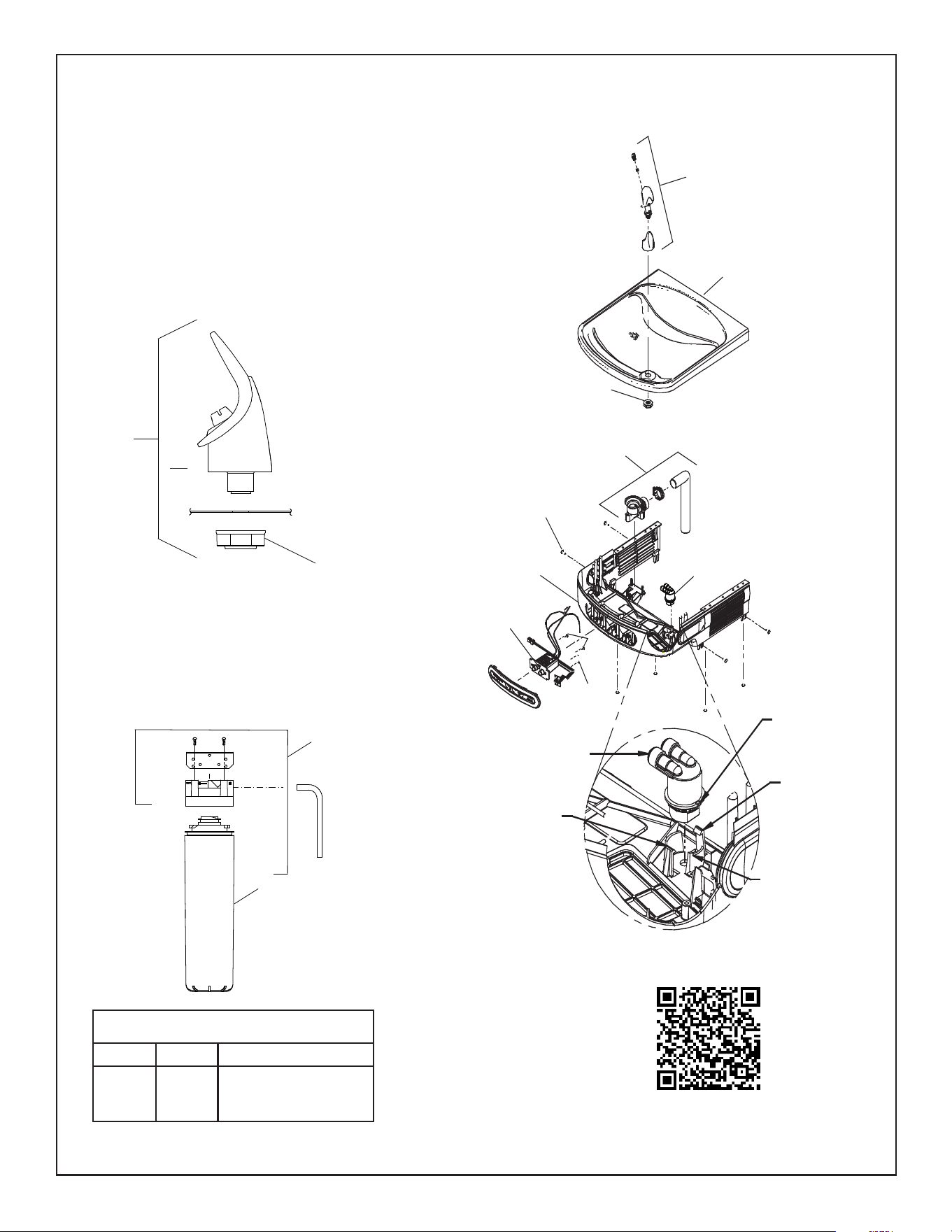
Fig. 5
DESCRIPTION
1
2
ITEM NO. PART NO.
51299C
0000000746
Filter Assy-1500 Gal.
Assy-Filter & Bracket
includes Fltr Head/Mtg Bkt/
John Guest Ftgs/Screws
FILTER PARTS LIST
Filter Detail
2
1
Scan for troubleshooting information and to subscribe to
automatic lter replacements at a discount.
SNAP
SNAP
ALIGNMENT
PEG
ALIGNMENT
NOTCH
REGULATOR
ASSEMBLY
Lower and Upper Shroud
To access the refrigeration system and plumbing connections, remove four screws from bottom
of cooler to remove the lower shroud. To remove the upper shroud for access to the pushbars,
regulator, solenoid valve or other components located in the top of the unit, remove lower shroud,
disconnect drain, remove four screws from tabs along lower edge of upper shroud, unplug two wires
and water tube.
Bubbler
To remove the bubbler, rst disconnect the power supply. The underside of the bubbler can be
reached through the access panel (Item 21, Page 2) on the underside of the shroud (Item 3).
Remove the access panel by removing the retaining screw. To remove the bubbler, loosen locknut
from the underside of the bubbler and remove the tubing from the quick connect tting per the
Operation Of Quick Connect Fittings section in the General Instructions. After servicing, replace the
access panel and retaining screw.
Service Instructions
FIG. 3
10
2
18
3
Sensor Eye
Adjustment Screw
FIG. 4
10
13
7
18
Basin
Locknut
BUBBLER DETAIL
NOTE:
When installing replacement bubbler and pedestal, tighten
locknut only to hold parts snug in position. Do Not Overtighten.
10
8
Note: Danger! Electrical shock hazard. Disconnect power before servicing unit.
EXPLODED BASIN
SHOWN FOR CLARITY
Page 6
LZO8*1H LZO8*2H LZO8*3H LZOD*1H
1000003484 (Rev. F - 03/25)
PRINTED IN U.S.A.
FOR PARTS, CONTACT YOUR LOCAL DISTRIBUTOR OR CALL 1.800.834.4816
ELKAY MANUFACTURING COMPANY • 1333 BUTTERFIELD ROAD,SUITE 200 • DOWNERS GROVE, IL 60515 • 630.574.8484 • www.elkay.com
REPAIR SERVICE INFORMATION TOLL FREE NUMBER 1.800.260.6640
PART
NO.
DESCRIPTION
ITEM
NO.
115V PARTS LIST
*INCLUDES RELAY & OVERLOAD. IF UNDER WARRANTY, REPLACE WITH
SAME COMPRESSOR USED IN ORIGINAL ASSEMBLY.
NOTE: All correspondence pertaining to any of the above water coolers or orders
for repair parts MUST include Model No. and Serial No. of cooler, name and part
number of replacement part.
*3
9
14
19
22
23
NS
NS
1000002147
1000002146
1000004575
0000000245
98751C
98752C
36066C
33133000
28030C
35826C
Compressor Serv. Pak (220V/50Hz)
Compressor Serv. Pak (220V/60Hz)
Kit - Solenoid Valve/Reg./Nut Assy.
Kit - Fan Motor/Blade (220V 50Hz-60Hz)
Kit - Overload/Relay/Cover (220V/50Hz)
Kit - Overload/Relay/Cover (220V/60Hz)
Power Cord
Adapt - Tab .250
Brkt - Power Inlet
Inlet Power
220V PARTS LIST
ITEM
NO.
PART
NO.
DESCRIPTION
NS = Not Shown
28401C
55001109
2000001903
36322C
56092C
66703C
97970C
1000004564
1000004572
56073C
30873C
98773C
75710C
98775C
98776C
98777C
98778C
98898C
0000000238
98724C
56213C
36287C
1000006146
27416C
27413C
Hanger Bracket
Basin - Stainless Steel
Shroud Assembly LZO
Compressor Serv. Pack
Poly Tubing (Cut to Length)
Drier
Kit - Drain Replacement (EZ)(Brkt/Tube/Ftg/Clamp)
Kit - Regulator w/Holder & Nut
Kit - Solenoid Valve/Regulator/Nut Assy.
Kit - Bubbler Assy/Nut
Wire - Jumper
Kit - Cold Control/Screws
2-28 x .250 48-2 Plastite Screw
Kit - Fan Motor Assy/Blade/Motor/Shroud/Screws/Nut
Kit - Condenser/Drier
Kit - Compr Mtg Hdwe/Grommets/Clips/Studs
Kit - Heatx/Drier
Kit - Hardware (EZ) for Panels
Kit - Compr Elect Relay/Overload/Cover
Kit - Evaporator Replacement Assy.
Panel - Access
Power Cord (Refrig. Unit)
Power Cord (Less Refrig. Unit)
Kit - Wrapper - Stainless
Kit - Wrapper - Light Grey
1
2
3
*4
5
6
7
8
9
10
11
12
13
14
15
16
17
18
19
20
21
22
NS
NS = Not Shown
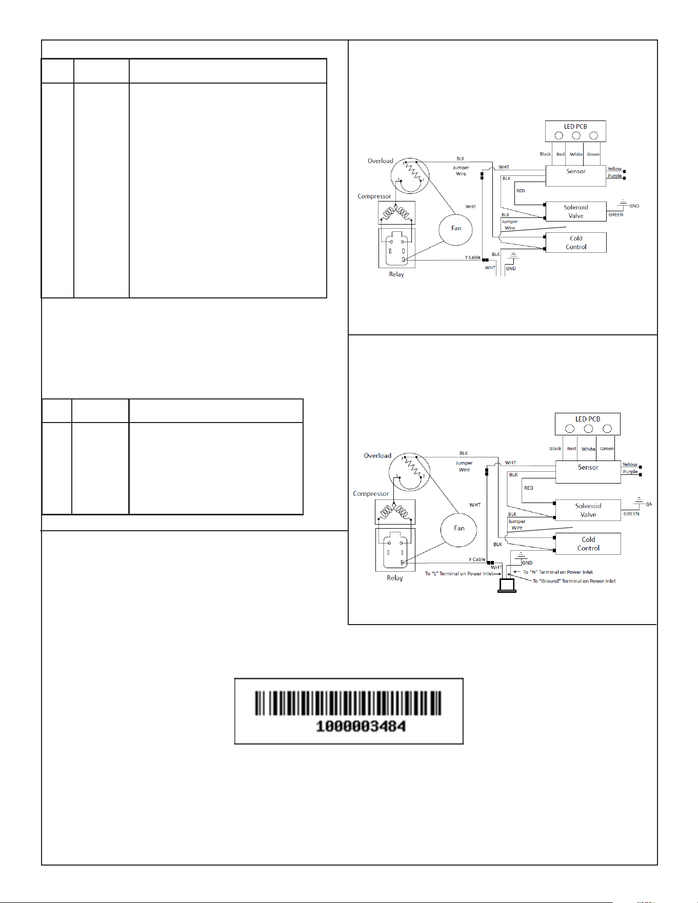
11
WIRING DIAGRAM - LZO 115V
FIG. 7
WIRING DIAGRAM - LZO 220V
FIG. 8
11