Page 1
EDFPB117C, EDFPBM117C, EDFPB117RAC, EDFPBM117RAC, EDFPBV117C,
EDFPBMV117C, EDFPBV117RAC, EBFPBMV117RAC
97922C (Rev. G - 6/08)
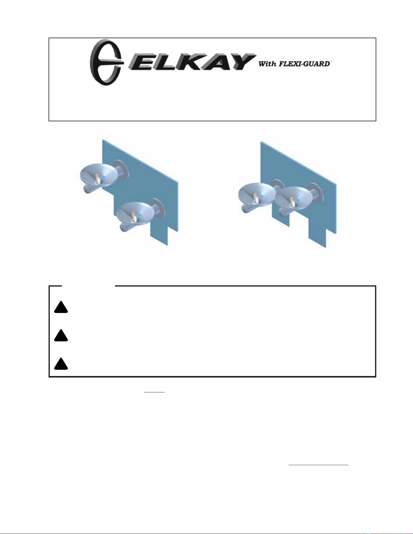
SWIRLFLO fountains with FLEXI-GUARD
INSTALLATION, CARE & USE MANUAL
TM
TM
!
CAUTION
:
Review these instructions before beginning installation. Be sure that installation
conforms to all plumbing, electrical and other applicable codes.
!
WARNING
:
When installation is complete, ensure these instructions are left in the plastic bag
provided inside the installed unit for future reference.
!
WARNING
:
Service to be performed by authorized service personnel only.
INSTALLER
NOTE: It is common practice to ground electrical hardware such as telephones, computers and other devices
to available water lines. This can, however, cause electrical feedback in the plumbing circuit, which
results in an “electrolysis” effect occurring in the fountain. This may result in water which has a metallic
taste to it or has a noticeable increase in the metallic content of the water.
When inspecting plumbing circuit, remember the line may be grounded some distance from the
installation, and may occur outside the building or area in which the unit is being installed.
This condition can be avoided (in most cases) by using recommended materials during installation. Any
drain fittings provided by the installer should be made of plastic which will electronically isolate the
fountain from the remainder of the building’s plumbing circuits.
EDFPBM(V)117C EDFPBM(V)117RAC
EDFPB117C, EDFPBM117C, EDFPB117RAC, EDFPBM117RAC, EDFPBV117C,
EDFPBMV117C, EDFPBV117RAC, EBFPBMV117RAC
Page 2
97922C (Rev. G - 6/08)
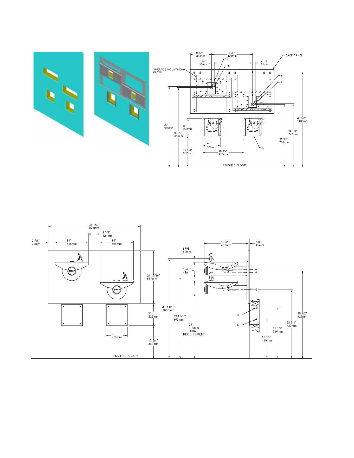
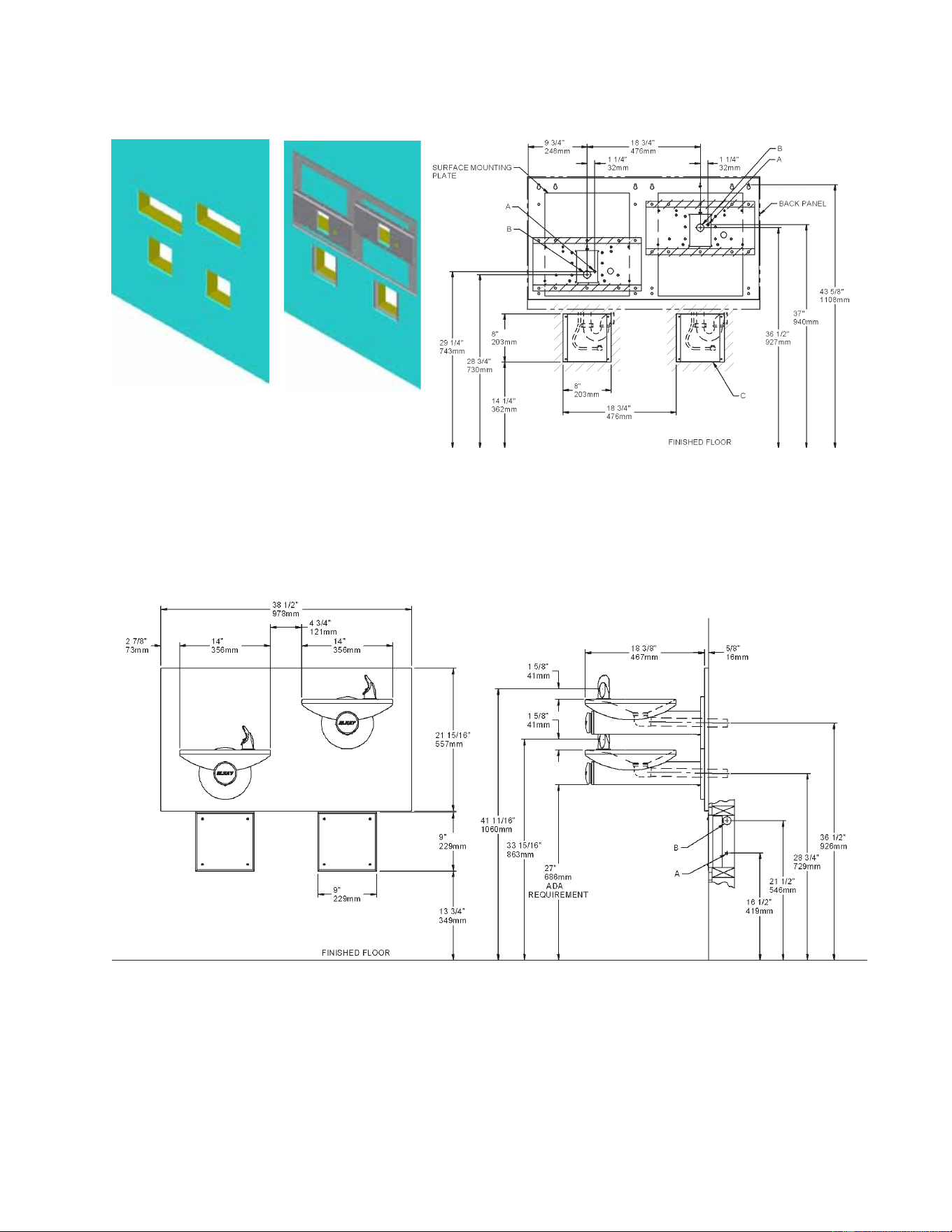
LEGEND
A = Water Inlet Location Left Or Right Side. 3/8” O.D. Unplated Copper Tube Connect.
B = Fountain Waste Location Left Or Right Side. Waste Is Shown in Wall But May Be Behind
Wall. 1-1/4” O.D. Drain (Trap Not Furnished)
C = Opening For Optional AP-99 Access Panel
Note: Reinforce The Wall In The Shaded Areas.
Figure 2 - Rough-in Assembly EDFPBM(V)117C
Figure 1 - Rough-in EDFPBM(V)117C
Optional
Page 3
EDFPB117C, EDFPBM117C, EDFPB117RAC, EDFPBM117RAC, EDFPBV117C,
EDFPBMV117C, EDFPBV117RAC, EBFPBMV117RAC
97922C (Rev. G - 6/08)
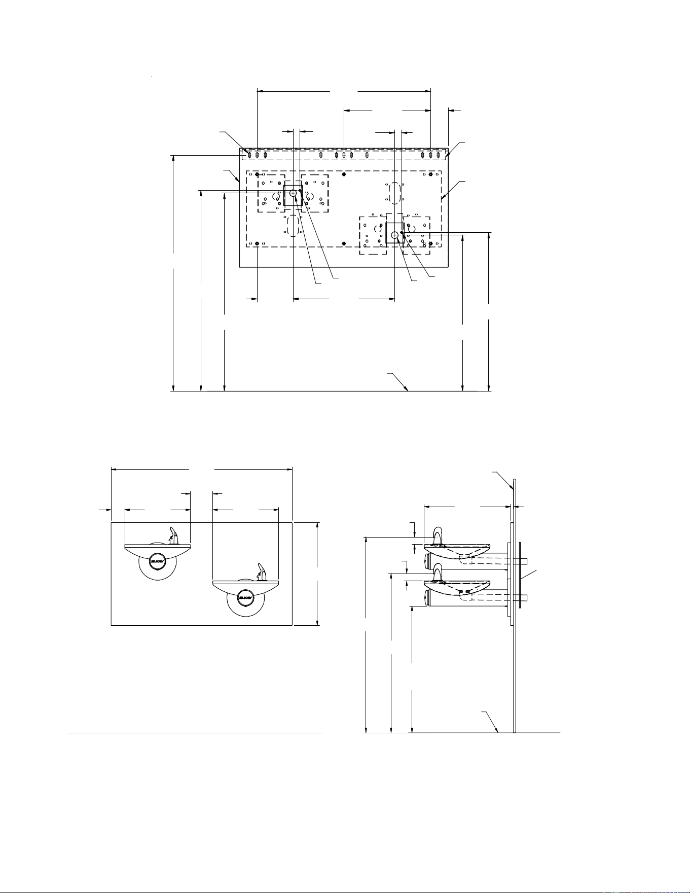
LEGEND
A = Water Inlet Location Left Or Right Side. 3/8” O.D. Unplated Copper Tube Connect.
B = Fountain Waste Location Left Or Right Side. Waste Is Shown in Wall But May Be Behind
Wall. 1-1/4” O.D. Drain (Trap Not Furnished)
C = Opening For Optional AP-99 Access Panel
Note: Reinforce The Wall In The Shaded Areas.
Figure 3 -Rough-in EDFPBM(V)117RAC
Figure 4 -Rough-in Assembly EDFPBM(V)117RAC
Optional
EDFPB117C, EDFPBM117C, EDFPB117RAC, EDFPBM117RAC, EDFPBV117C,
EDFPBMV117C, EDFPBV117RAC, EBFPBMV117RAC
Page 4
97922C (Rev. G - 6/08)
43 1/2"
1105mm
36 1/2"
927mm
37"
940mm
28 3/4"
730mm
29 1/4"
743mm
6 5/8"
168mm
18 3/4"
476mm
1 1/4"
32mm
1 1/4"
32mm
3 1/4"
82mm
16"
406mm
32"
813mm
B
A
A
B
HANGER BRACKET
BACK PANEL
MPW200
MTG. PLT.
C
FINISHED FLOOR
27"
686mm
ADA
REQUIREMENT
5/8"
16mm
18 3/8"
467mm
21 15/16"
557mm
2 7/8"
73mm
14"
356mm
4 3/4"
121mm
14"
356mm
38 1/2"
978mm
33 15/16"
862mm
41 11/16"
1059mm
1 5/8"
41mm
1 5/8"
41mm
FINISHED FLOOR
FINISHED WALL
Figure 5 -Rough-in EDFPB(V)117C
Figure 6 -Rough-in Assembly EDFPB(V)117C
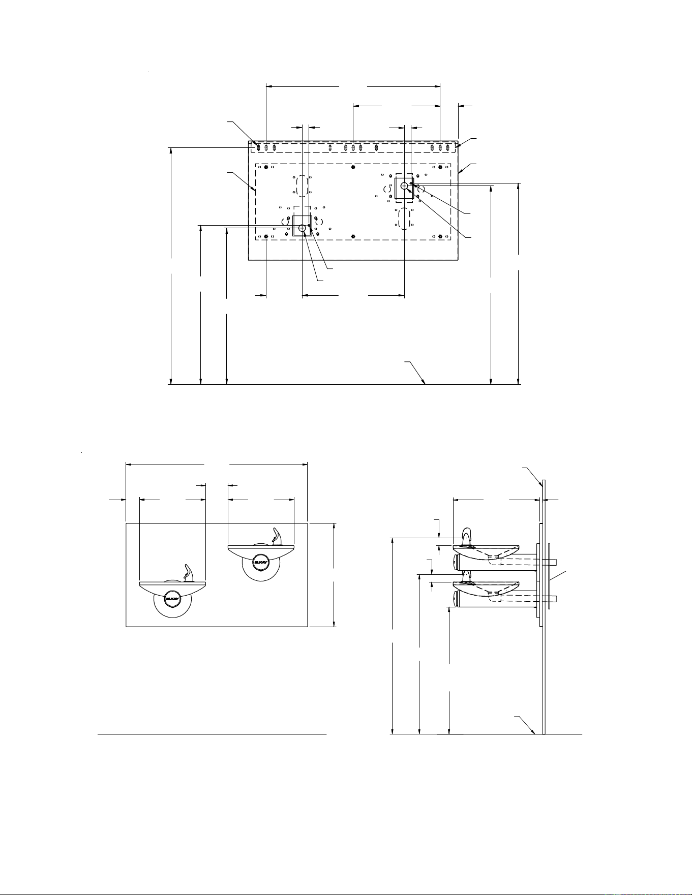
LEGEND
A = Water Inlet Location Left Or Right Side. 3/8” O.D. Unplated Copper Tube Connect.
B = Fountain Waste Location Left Or Right Side. Waste Is Shown in Wall But May Be Behind
Wall. 1-1/4” O.D. Drain (Trap Not Furnished)
C = 3/8” (10mm) DIA. Slots For Mounting Hanger Bracket To Wall
MPW200 MTG. PLT.
REF. SEPARATE
INSTALLATION
INSTRUCTIONS
FOR DETAILS
Page 5
EDFPB117C, EDFPBM117C, EDFPB117RAC, EDFPBM117RAC, EDFPBV117C,
EDFPBMV117C, EDFPBV117RAC, EBFPBMV117RAC
97922C (Rev. G - 6/08)
5/8"
16mm
18 3/8"
467mm
27"
686mm
ADA
REQUIREMENT
33 15/16"
862mm
1 5/8"
41mm
41 11/16"
1059mm
1 5/8"
41mm
FINISHED FLOOR
FINISHED WALL
21 15/16"
557mm
2 7/8"
73mm
14"
356mm
4 3/4"
121mm
14"
356mm
38 1/2"
978mm
Figure 7 -Rough-in EDFPB(V)117RAC
Figure 8 -Rough-in Assembly EDFPB(V)117RAC
36 1/2"
927mm
37"
940mm
28 3/4"
730mm
29 1/4"
743mm
3 1/4"
82mm
16"
406mm
32"
813mm
1 1/4"
32mm
1 1/4"
32mm
6 5/8"
168mm
18 3/4"
476mm
HANGER BRACKET
BACK PANEL
MPW200
MTG. PLT.
A
B
A
B
C
FINISHED FLOOR
43 1/2"
1105mm
LEGEND
A = Water Inlet Location Left Or Right Side. 3/8” O.D. Unplated Copper Tube Connect.
B = Fountain Waste Location Left Or Right Side. Waste Is Shown in Wall But May Be Behind
Wall. 1-1/4” O.D. Drain (Trap Not Furnished)
C = 3/8” (10mm) DIA. Slots For Mounting Hanger Bracket To Wall
MPW200 MTG. PLT.
REF. SEPARATE
INSTALLATION
INSTRUCTIONS
FOR DETAILS
EDFPB117C, EDFPBM117C, EDFPB117RAC, EDFPBM117RAC, EDFPBV117C,
EDFPBMV117C, EDFPBV117RAC, EBFPBMV117RAC
Page 6
97922C (Rev. G - 6/08)
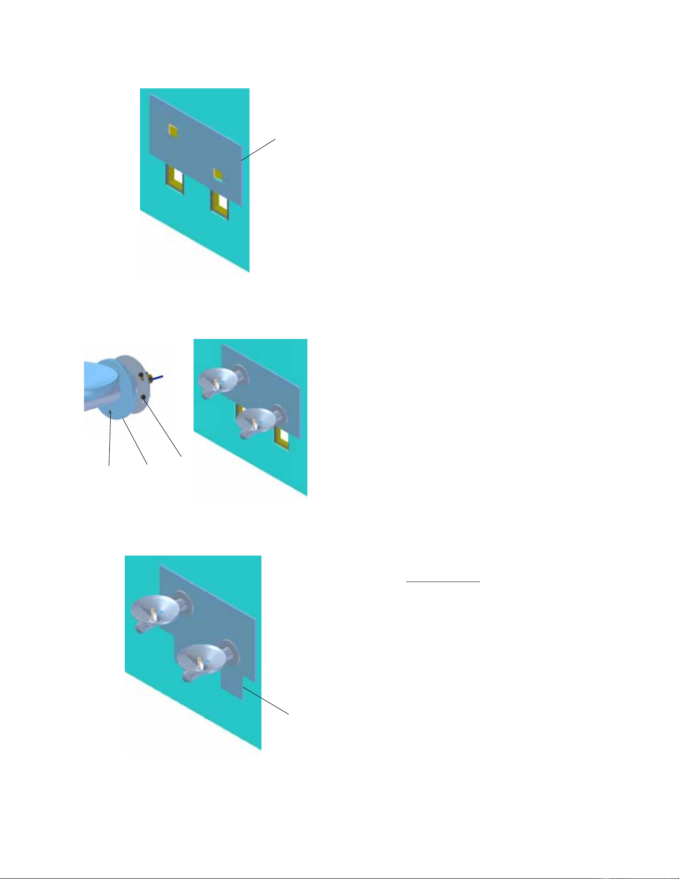
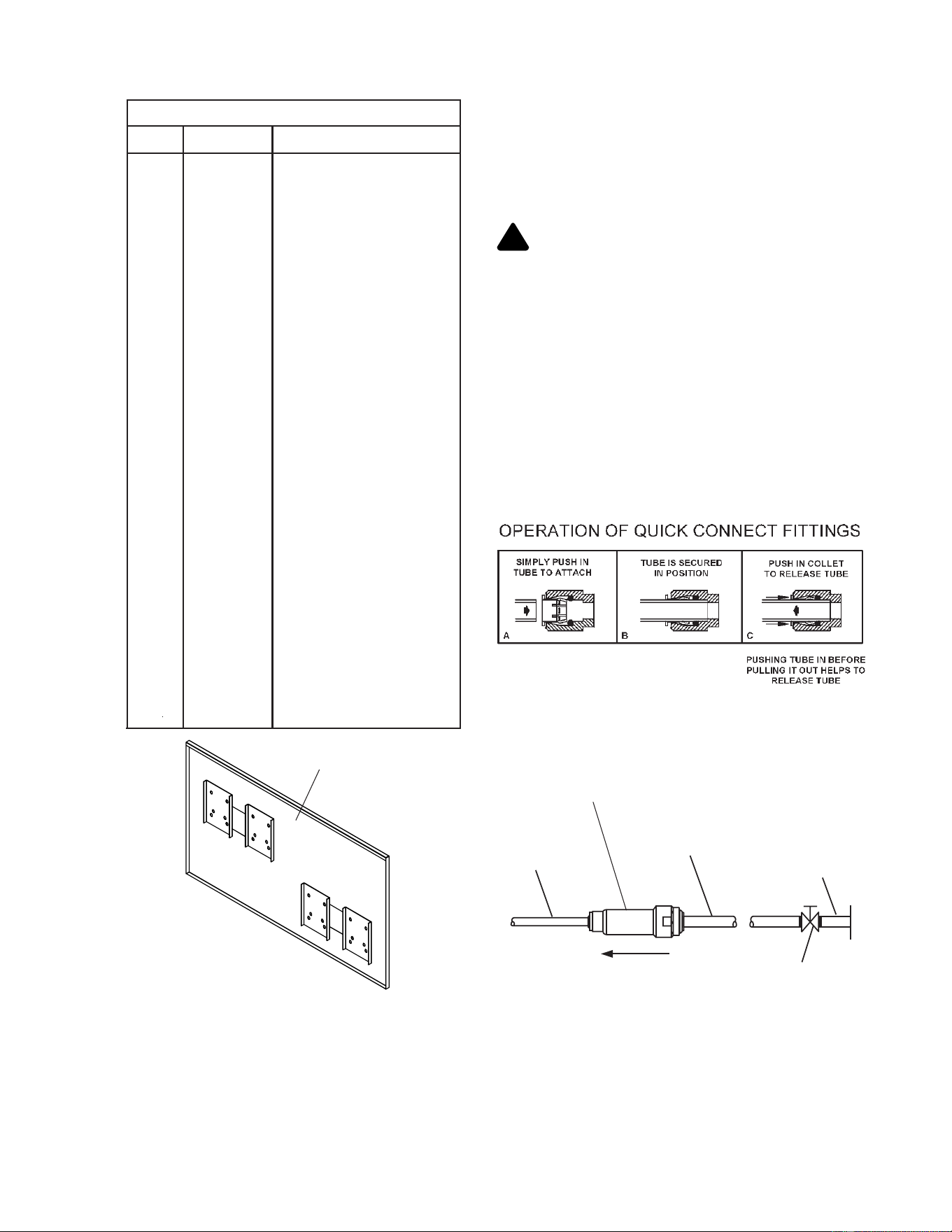
Figure 9 -Panel Installation
Figure 10 - Fountain Installation
Figure 11 - AP-99 Panel (Optional)
30
28
Installation Instructions:
1. Fountains using the MPW Mounting Plate refer to Figures
5 or 7 for hanger bracket location and rough-in dimensions.
NOTE: Review separate installation instructions for details of the
MPW Mounting Plate.
Fountains using the Wall Plate Assy. refer to Fig’s. 1 or 3
for rough-in dimensions.
2. Shown dimensions pertain to installation location (framing must
support up to 300 lbs. weight). These dimensions are required for
compliance with ANSI Standard A117.0.
3. Install rough-in plumbing as shown in Fig’s. 1, 3, 5, or 7. Run
supply water inlet line through the back panel. Install a service
stop (not provided). Turn on supply water and flush thoroughly.
4. Installing back panel.
Ftn. w/MPW Mounting Plate: Refer to Fig. 16 for placement
of braces onto back panel. Place the upper edge of the panel
above the hanger bracket. Slide the panel down until it engages
the hanger bracket. Be sure back panel is firmly engaged before
releasing it.
Ftn. w/Wall Plate Assy.: Place the upper edge of the panel
above mounting plate on the wall. Slide the panel down until it
engages the mounting plate. Be sure back panel is firmly engaged
before releasing it. (See Figure 9)
5. Install fountain. Remove screw (Item 28) from cover
plate and slide cover plate (Item 14) toward basin. (See Figure 10)
Ftn. w/MPW Mounting Plate: Mount the fountain to the back
panel and wall using (4) 5/16” x 6” long threaded rods, washers,
and nuts (provided). Tighten securely.
Ftn. w/Wall Plate Assy.: Mount the fountain to the back panel
and wall plate assy. with (4) 5/16” x 1” (25mm) long screws
(Item 30 - provided). Tighten securely.
6. Determine required length of waste line and cut to
appropriate length. 1-1/4” O.D. waste tube furnished.
1-1/4” slip trap, waste elbow and extension not provided.
7. Make water supply connections from service stop to the
3/8” O.D. unplated copper tube coming out of the strainer. Turn on
water supply and check for leaks (See Figure 17). Newly installed
water supply line should be insulated after leak check is
completed.
CAUTION: DO NOT SOLDER tubes inserted
into the strainer as damage to the
o-rings may result.
8. These products are designed to operate on 20-105 PSIG supply
line pressure. If the inlet pressure is above 105 PSIG, a pressure
regulator must be installed in the supply line. Any damage caused
by reason of connecting these products to supply line pressures
lower than 20 PSIG or higher than 105 PSIG is not covered by
warranty.
9. Check stream height from bubbler. Stream height is factory set at
35 PSI. If supply pressure varies greatly from this, remove push
button (Item 17 - Figure 14) and adjust the screw on the regulator
(Item 19 - Figure 14). To remove push button, remove setscrew
from bottom of sleeve (Item 15). Insert a small punch in screw
hole and push up while grasping the push button and pull forward
removing the push button. Clockwise adjustment will raise stream
height and counterclockwise movement will lower stream height.
For best adjustment stream should hit basin approximately 6-1/2”
from the bubbler. Reassemble the push button by pushing in on
button until the push button catches in the sleeve. Reinstall the
setscrew (Item 31) in the sleeve (Item 15).
25
26
14
Page 7
EDFPB117C, EDFPBM117C, EDFPB117RAC, EDFPBM117RAC, EDFPBV117C,
EDFPBMV117C, EDFPBV117RAC, EBFPBMV117RAC
97922C (Rev. G - 6/08)
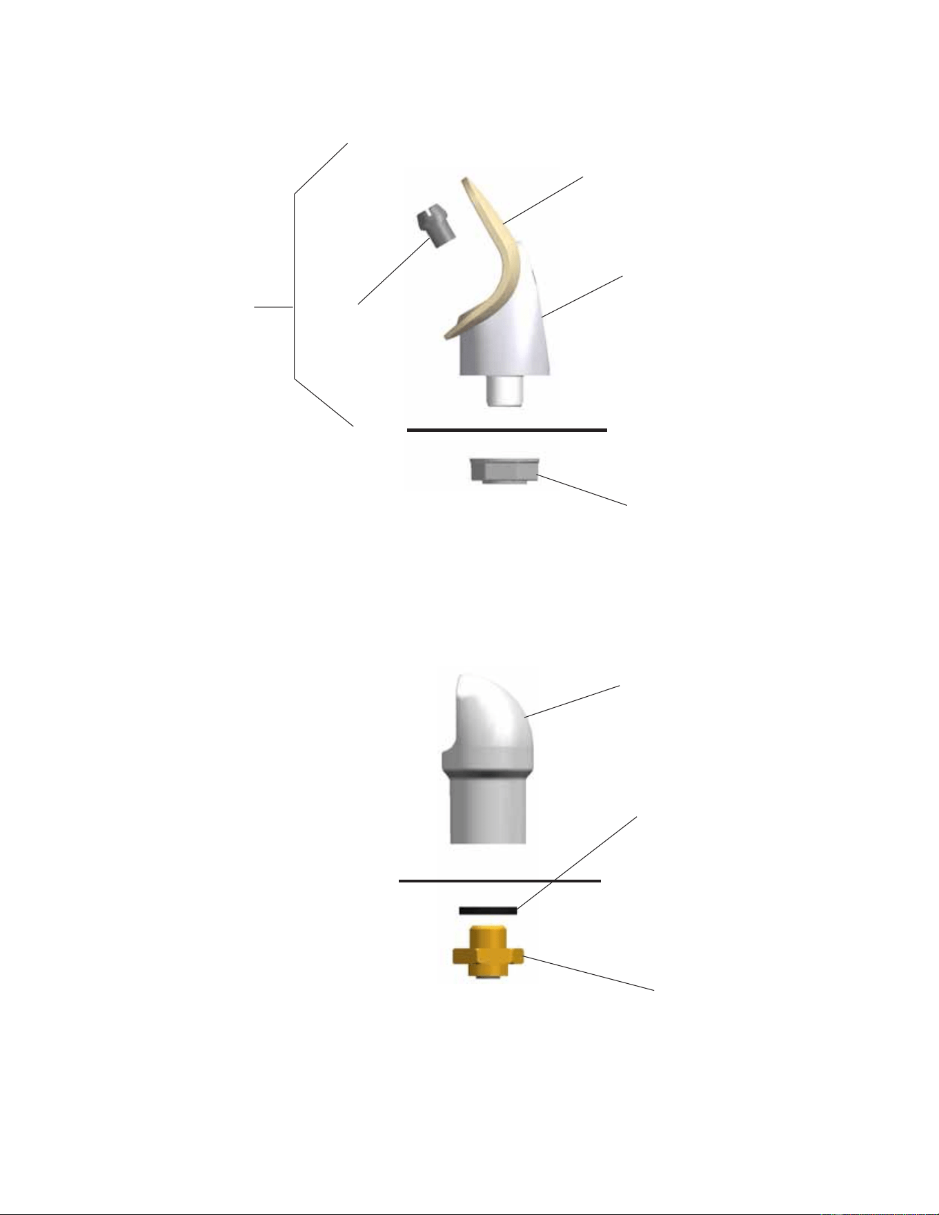
BUBBLER DETAIL
VANDAL RESISTANT
BUBBLER DETAIL
NOTE:
When installing replacement bubbler and pedestal, tighten
nut (Item 7) only to hold parts snug in position. Do Not
Overtighten.
Figure 12 - Bubbler Details
BASIN
5
6
7
2, 3, 4
1
8
9
10
BASIN
EDFPB117C, EDFPBM117C, EDFPB117RAC, EDFPBM117RAC, EDFPBV117C,
EDFPBMV117C, EDFPBV117RAC, EBFPBMV117RAC
Page 8
97922C (Rev. G - 6/08)
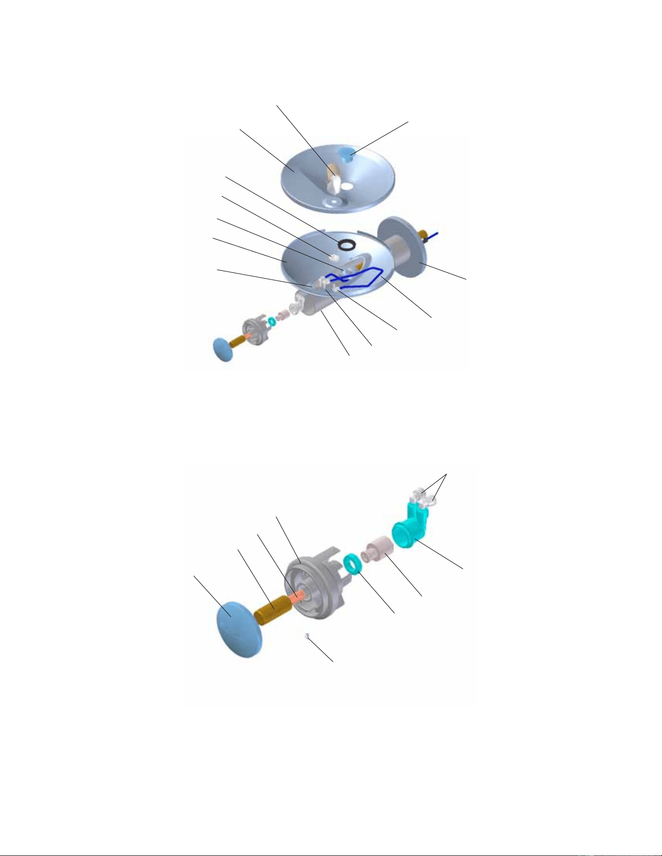
Figure 13 - Fountain Body
Figure 14 - Push Button
15
16
17
18
19
20
31
32
11
21
See Fig. 12
12
24
29
13
22
27
14
23
See Fig. 12
32
34
Page 9
EDFPB117C, EDFPBM117C, EDFPB117RAC, EDFPBM117RAC, EDFPBV117C,
EDFPBMV117C, EDFPBV117RAC, EBFPBMV117RAC
97922C (Rev. G - 6/08)
Figure 17 – Water Supply Connections
NOTE: WATER FLOW
DIRECTION
SERVICE STOP
(NOT FURNISHED)
BUILDING WATER INLET
3/8" O.D. UNPLATED
COPPER TUBE CONNECT
COLD WATER SUPPLY
1/4" O.D. TUBE
WATER INLET
TO COOLER
TROUBLESHOOTING & MAINTENANCE
Orifice Assembly: Mineral deposits on orifice
can cause water flow to spurt or not regulate. Mineral
deposits may be removed from the orifice by poking
with a small round file not over 1/8” diameter, or using a
small diameter wire.
!
CAUTION
:
DO NOT file or cut orifice
material.
Stream Regulator: If orifice is clean, regulate
flow as in Step 8 of the installation instructions. If
replacement is necessary, see parts list for correct
regulator part number.
Actuation of Quick Connect Water
Fittings: Cooler is provided with lead-free connec-
tors which utilize an o-ring water seal. To remove
tubing from the fitting, relieve water pressure, push in
on the gray collar while pulling on the tubing. (See
Figure 15) To insert tubing, push tube straight into
fitting until it reaches a positive stop (approximately 3/4”).
Figure 15 – Quick Connect Fittings
PARTS LIST
ITEM NO.
PART NO.
DESCRIPTION
1
2
3
4
5
6
7
8
9
10
11
12
13
14
15
16
17
18
19
20
21
22
23
24
25
26
27
28
29
30
31
32
33
34
35
NS
56073C
40319C
50171C
50314C
56011C
55997C
75580C
98118C
100322740560
15009C
28474C
28473C
45767C
28343C
45781C
45847C
45848C
50986C
61313C
15005C
56163C
45769C
45768C
56092C
28392C
28393C
AP99
111008343890
70432C
38417001
75560C
75632C
70817C
55996C
75671C
28844C
28845C
27090C
Bubbler Assy
Fitting - Orifice
O-Ring
Orifice - Flow Straightener
Housing Assembly
Pedestal
Bubbler Locknut
Bubbler Assembly VR
Gasket - Black .68 x 1.03 VR
Nipple - Bubbler VR
Basin - Swirlflow
Lower Shell
Fountain Body
Cover Plate
Sleeve
Pin - Push Button
Push Button
Holder - Regulator
Regulator
Retaining Nut
Gasket - Drain
Assy - Drain/Tailpipe
Drain - Plug 1-1/2”
Poly Tubing (Cut To Length)
Back Panel RH ADA
Back Panel LH ADA
AP-99 Panel (Optional)
Screw - #10-24 x .62 HHMS
Screw - #8-32 x .38 THSM
Screw - #8-18 x .37 HHSM
Screw - 5/16-18 x 1.00 HHMS
Setscrew - #10-32 x .31
Fttng - Elbow 1/4 x 1/4
Strainer
Spring - Push Button
Back Panel Assy RH ADA
Back Panel Assy LH ADA
Hanger Bracket
FOR PARTS, CONTACT YOUR LOCAL DISTRIBUTOR OR CALL 1.800.323.0620
ELKAY MANUFACTURING COMPANY · 2222 CAMDEN COURT · OAK BROOK, IL 60523 · 630.574.8484
PRINTED IN U.S.A.
33
35
Installing Back Panel: When installing back panel
assy. (Item 35) with MPW (Mounting Plate), attach
channel braces as shown above. Remove the
protective backing from the tape installed on the
braces. Line up the corresponding holes in the
braces and back panel and press firmly in place.
Figure 16 – Back Panel Assembly