Pre-Installation
TOOLS REQUIRED
Adjustable
wrench
Step ladder
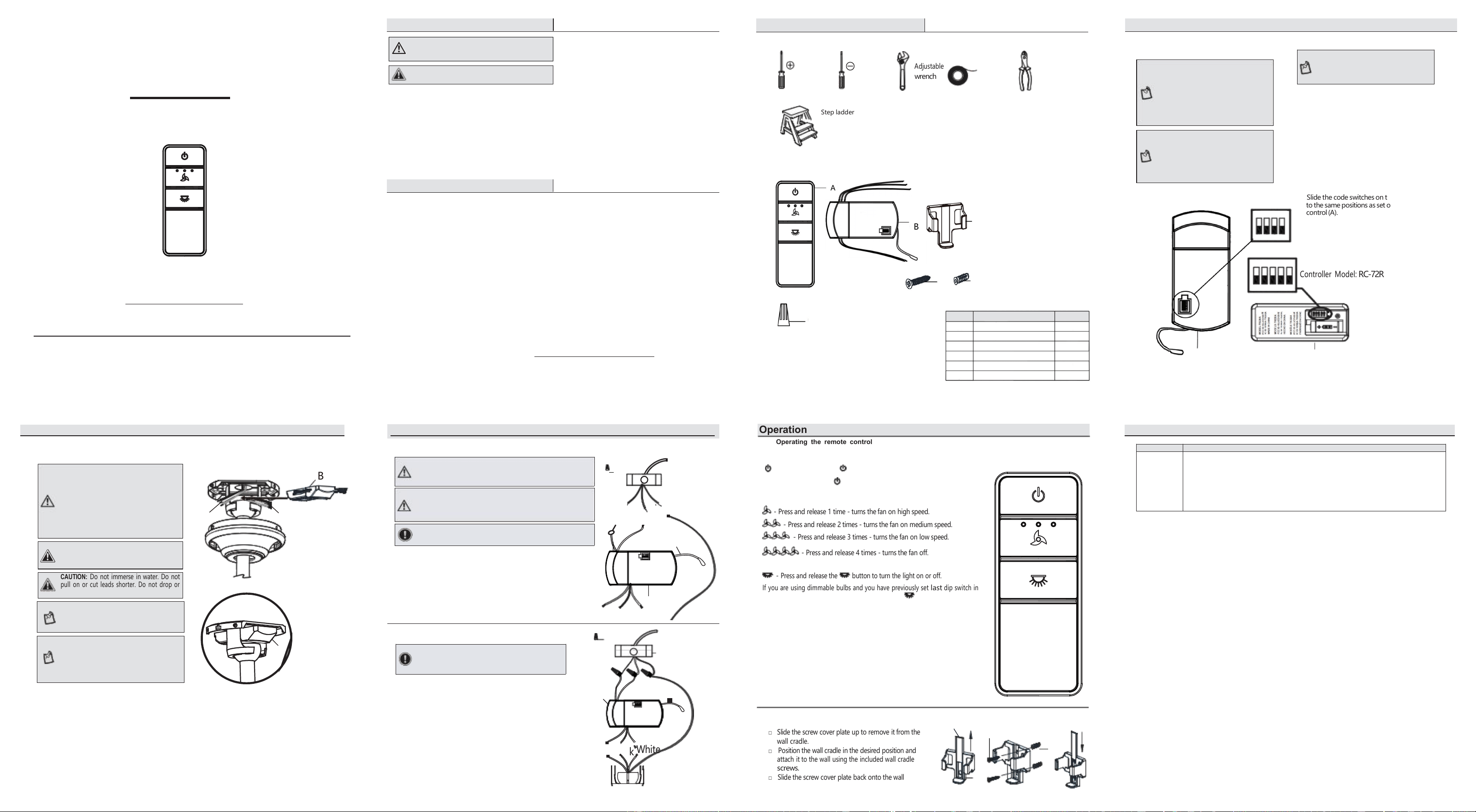
Operation
Operating the remote control
B
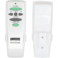
- Press and release 1 time - turns the fan on high speed.
- Press and release 2 times - turns the fan on medium speed.
- Press and release 3 times - turns the fan on low speed.
- Press and release 4 times - turns the fan off.
- Press and release the button to turn the light on or off.
If you are using dimmable bulbs and you have previously set
last
dip switch in
your remote to the“5”position, press and hold the button to activate the
dimmer function.
NOTE: The battery will weaken with age and
should be replaced before leaking takes
place as this will damage the transmitter.
Dispose of used battery properly. Keep the
remote out of the reach of children.
□
Slide the screw cover plate up to remove it from the
wall cradle.
□ Position the wall cradle in the desired position and
attach it to the wall using the included wall cradle
screws.
□ Slide the screw cover plate back onto the wall
cradle to conceal the screws.
NOTE: It is imperative that the code used
for both transmitter and receiver is exactly
the same, otherwise remote controller will
not work.
CAUTION: Do not immerse in water. Do not
pull on or cut leads shorter. Do not drop or
bump the unit.
Installation (continued)
Wiring the receiver to the household wiring
WARNING: To avoid possible electrical shock, turn the
electricity off at the main fuse box before wiring. If you
feel you do not have enough electrical wiring knowledge or
experience, contact a licensed electrician.
WARNING: Each wire not supplied with this fan is designed to
accept up to one 1 2 - gauge house wire and two wires from the
fan. If you have larger than 1 2 - gauge house wiring or more
than one house wire to connect to the fan wiring, consult an
electrician for the proper size wire nuts to use.
IMPORTANT: Use the wire connecting nuts(C) supplied with
your fan. Secure the connectors with electrical tape and
ensure there are no loose strands or connections.
□ Spread the wires apart so that the green and white wires are on one
side of the outlet box and the black wire is on the other side.
□
Connectthegreenfanwires to the householdground wire (this may
beagreen or barewire) using a wire connecting nut(C).
□ Connectthereceiverblack(orred)wire to the household black (hot)
wire using a wire connecting nut (C).
□ Connectthe receiverwhite wire to the household white wire (neutral)
wire using a wire connecting nut (C).
□
Secureeach wire connecting nut using electricaltape.
(MM)
□
Connect thefanmotorwhite wire tothe receiver white wire
usinga wire connecting nut (C).
□ Connectthe fanmotorblack wire to the receiver black wire
usinga wire connecting nut (C).
□
Connect the fan motor bluewire to thereceiver blue wire
usinga wire connecting nut (C).
□
Secure each wire connectingnut usingelectrical tape.
□ Turnthewire connecting nut(C) upward and pushthe wiring
intotheoutlet box(MM).
This equipment has been tested and found to comply with the limits for a Class B digital device,
pursuant to Part 15 of the FCC Rules. These limits are designed to provide reasonable protection
against harmful interference in a residential installation. This equipment generates, uses and can
radiate radio frequency energy and, if not installed and used in accordance with the instructions, may
cause harmful interference to radio communications. However, there is no guarantee that interference
will not occur in a particular installation. If this equipment does cause harmful interference to radio
or television reception, which can be determined by turning the equipment off and on, the user is
encouraged to try to correct the interference by one or more of the following measures:
--Reorient or relocate the receiving antenna.
--Increase the separation between the equipment and receiver.
--Connect the equipment into an outlet on a circuit different from that to which the receiver is
connected.
--Consult the dealer or an experienced radio/TV technician for help.
CAUTION:
Any changes or modifications not expressly approved by the grantee of this device could void the
user’s authority to operate the equipment.
This device complies with Part 15 of the FCC Rules. Operation is subject to the following two
conditions: (1) This device may not cause harmful interference, and (2) this device must accept any
interference received, including interference that may cause undesired operation.
The supplier warrants the remote control and receiver to be free from defects in workmanship and
material present at time of shipment from the factory for a period of one year after the date of purchase
by the original purchaser. We agree to correct such defects without charge or at our option replace with
a comparable or superior model if the product is returned. To obtain warranty service, you must present
a copy of the receipt as proof of purchase. All costs of removing and reinstalling the product are your
responsibility. Damage to any part such as by accident or misuse or improper installation or by affixing
any accessories, is not covered by this warranty. Servicing performed by unauthorized persons shall
render the warranty invalid. There
wa
s no other express warranty. The duration of any implied warranty
which cannot be disclaimed is limited to the time period as specified in the express warranty. Some
states do not allow a limitation on how long an implied warranty lasts, so the above limitation may not
apply to you. The retailer shall not be liable for incidental, consequential, or special damages arising out
of or in connection with product use or performance except as may otherwise be accorded by law. Some
states do not allow the exclusion of incidental or consequential damages, so the above exclusion or
limitation may not apply to you. This
warranty gives specific legal rights, and you may also have other
rights which vary from state to state.
This warranty supersedes all prior warranties.
Contact the Customer Service Team
by email: Support@ceilingfanremote.com
or visit
www.ceilingfanremote.com
5. Install the receiver into the ceiling fan canopy of
the fan to ensure proper protection.
6. This unit is to be used for the control of the ceiling
fan and in a AC110/120V 60Hz power supply only.
7. Acceptable for installation in damp locations. Do
not immerse in water.
8. The remote must be stored in a dry location when
not in use.
9. Electrical diagrams are for reference only.
10. Do not pull on or cut leads shorter.
11. Do not drop or bump the unit.
12. After making the electrical connections, secure
each with electrical tape; spliced conductors
should be turned upward and pushed carefully up
into the outlet box. The wires should be spread
apart with the grounded conductor and the
equipment-grounding conductor on one side of
the outlet box.
Setting the Code on the Remote
□
Removethe battery cover on theback ofthe
remotecontrol(A)by pressingfirmly on the
arrowand sliding the cover off.
□ Slide the code switches to your choice of
eitherup or down. Thefactory setting is up.
□ For fans with dimmable bulbs, slide the dip
control(A)
□ Install the 23A battery (12V) (NOT included).
□
Replace the battery cover on the remot
switch O/D tothe positionmarked“
D”, if
you arenot using dimmable bulbsslide the
dip switchtothe“O ”position.
e
.
Setting the Code on the Receiver
to the samepositions as set on the remote
□
Slide the code switches on the receiver (B)
control(A).
Problem
Solution
The fan will
not start.
□ Check the main and branch circuit fuses or breakers.
□ Check to make sure the wall switch is in the on position if applicable.
□ Check the line wire connections to the fan and switch wire connections in the switch
housing.
□ Check the battery in the transmitter.
□ Ensure you are in the normal range of 10-20 ft (3-6m).
□ Ensure the dip switch settings are the same on the transmitter and receiver.
□ Remember to turn off the power supply before checking the dip switches settings.
1. Read and save these instructions.
2. All wiring must be in accordance with the National
Electrical Code ANSI/NFPA 70-1999 and local electrical
codes. Electrical installation should be performed by a
qualified licensed electrician.
3. The supply to the remote control receiver should be
connected through a mains switch, i.e. existing wall
switch.
4. Disconnect from the power supply at the wall switch
before working on the remote control receiver or
ceiling fan.
WARNING: To reduce the risk of fire or
electric shock, remember to disconnect
power.The electrical wiring must meet
all local and national electrical code
requirements. The electrical source and fan
must be 110/120 volt, 60Hz. Do not use this
productinconjunction with anyvariable
wall control. Incorrect wire connection can
damage this receiver.
Weappreciatethetrustandconfidence youhaveplacedinour store throughthepurchase ofthisremote
control.Westrivetocontinuallycreatequalityproductsdesignedto enhanceyourhome. Visit us onlinetosee
our fulllineof productsavailableforyour home improvement needs.
Thankyouforchoosingourbrand !
□
Positionthehouse supply wires(AAA)
to one side of the slide-on mounting
bracket(A); positionthe fan wires(BBB)
to the opposite side.
□ Insert thenarrow end of the receiver
(asshown,flatsidetowards the ceiling)
into the slide-on mounting bracket
until it rests on top of the ball/downrod
assembly.
NOTE: The frequencies on your receiver
and hand unit have been preset at the
factory. Before installing the receiver,
make sure the dip switches on the
receiver and hand unit are set to the
same frequency. The dip switches on the
hand unit are located inside the battery
compartment.
Questions, problems, missing parts ? Beforereturning to the store, please
contactour customer support of the store you purchased, or mail to :
Support@ceilingfanremote.com
http://www.ceilingfanremote.com
NOTE: The battery will weaken with age
and should be replaced before leaking
takes place as this will damage the hand
unit. Dispose of the used battery properly
and keep the battery out of the reach of
children.
Black
White
Green
Antenna
IMPORTANT: Use the wire connecting nuts(C)
supplied with your fan. Secure the connectors
with electrical tape and ensure there are no loose
strands or connections.
- Press and release the button to turn the fan and the lights on or off.
□
Press and hold the button for 3 seconds to use the“walk away
NOTE: The ceiling fan must be set at HIGH
speed and light kit (if installed) should be
set to the ON position.
Installation
Troubleshooting
CAUTION: If other fan wires are a different
color, have this unit installed by a licensed
electrician.
WARNING: To reduce the risk of fire or injury,
do not use this product in conjunction with any
variable (rheostat) wall control
Installation (continued)
time delay”; this will activate the light for 30 seconds (if you are using
dimmable bulbs the light will be activated at 50% brightness).
CAUTION: Incorrect wire connections will damage
thisreceiver.
Receiver (B) correctly
positioned in the
mounting bracket.
1
Setting the codes on the
remote control and receiver
USE AND CARE GUIDE
Safety Information
Warranty
Green
Antenna
UNIVERSAL REMOTE CONTROL
2
Installing the receiver
Item: 072-01
Model: RC-72T& RC-72R
Outlet box
C (x3)
Outlet Box
inthe ceiling
(MM)
Mounting the remote control holder
AAA
BBB
Wiring the fan to the receiver
Green
Black
Black
(or Bare)
in the ceiling
Controller Model:
RC-72R
Screwcove
r
(or Red)
C (x3)
White
plate
Blue
3
2
1
4
H
B
B
G
B
F
Flathead
screw-
driver
Phillips
screw-
driver
Electrical
tape
Wire
cutter
CEILING FAN REMOTE CONTROL KIT
PACKAGE CONTENTS
A
C
B
D
Part
E
Description
A
B
C
D
E
F
Quantity
Transmitter
1
1
6
1
2
Receiver
Plasti wire connector
Wall mount
Wall mount screw
Plastic anchor
F
2
Antenna
B
A
ON
1 2
3 4 D
O
ON DIP
1
2 3
4