1
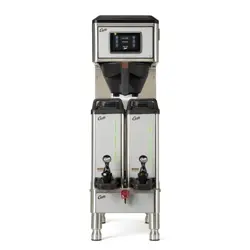
This Curtis Generation 4 Unit is Factory Pre-Set and Ready to Go Right from the Box.
Following are the Factory Settings for your G4 Coffee Brewing System:
• Brew Temperature = 200°F • Water Bypass = On for LARGE & MEDIUM Brew Only
• Brew Volume = Set to Vessel Requirement.
System Requirements:
• Water Source 20 – 90 PSI (Minimum Flow Rate of 1 GPM)
• Electrical: See attached schematic for standard model or visit www.wilburcurtis.com for your model.
Model
G4GEMT
CAUTION: DO NOT
connect this brewer to hot
water. The inlet valve is
not rated for hot water.
CAUTION: Please use
this setup procedure
before attempting to use
this brewer. Failure to follow the
instructions can result in injury or the
voiding of the warranty.
IMPORTANT: Equipment
to be installed to comply
with applicable govern-
mental plumbing/electrical codes
having jurisdiction.
ISO 9001:2008 REGISTERED
WILBUR CURTIS CO., INC.
6913 West Acco Street
Montebello, CA 90640-5403
For the latest information go to
www.wilburcurtis.com
Tel: 800-421-6150
Fax: 323-837-2410
For the latest specications and information go to www.wilburcurtis.com
Technical Support: 1-800-995-0417 M-F 5:30am-4:00pm PT
Email: [email protected]
This equipment is designed for commercial use. Any servicing other than cleaning and routine maintenance
should be performed by an authorized Wilbur Curtis Company Service Technician.
• DONOTimmersetheunitinwateroranyotherliquid
• Toreducetheriskofreorelectricshock,DONOTopenservicepanels.Therearenouserserviceable
parts inside.
• Keephandsandotheritemsawayfromhotareasoftheunitduringoperation.
• Nevercleanwithscouringpowdersorharshchemicals.
Important Safeguards/Symbols
Service Manual – G4 Gemini Twin Coffee Brewer
Wilbur Curtis Company, inC.
Symbols:
WARNINGS – To help avoid personal injury
Important Notes/Cautions – from the factory
Sanitation Requirements
NSF International requires the following water connection:
1. A quick disconnect or additional coiled tubing (at least 2x the depth of the unit) is required so
that the unit can be moved for cleaning.
2. This unit must be installed with adequate backow protection to comply with applicable federal,
state and local codes.
3. Water pipe connections and xtures directly connected to a portable water supply shall be sized,
installed and maintained in accordance with federal, state, and local codes.
3. Connect the unit to electrical outlet with appropriate amperage rating (see serial tag on machine).
4.Oncepowerhasbeensuppliedtotheunit,ipthetoggleswitchtothe‘ON’position(locatedontherearof
theunit),thewatertankwillbegintoll.Whenthewaterlevelinthetankreachestheprobe,theheating
element(s) will turn on.
5. Waterintheheatingtankwill requireapproximatelyahalfhourbeforereachingoperating temperature
(factorysettingof200°F).Whereapplicable,turnontheUniversalControlModule(UCM).Whentheunit
reachesoperatingtemperature,itwilldisplay“READYTOBREW”.
NOTE: A water ltration system must be used to help maintain trouble-free operation. In areas with
extremely hard water, we highly recommend the use of a Curtis approved water lter. For our full line
of lters, please log on to www.wilburcurtis.com. A water ltration system will greatly prolong the life
of the unit and enhance the quality and taste of the product.
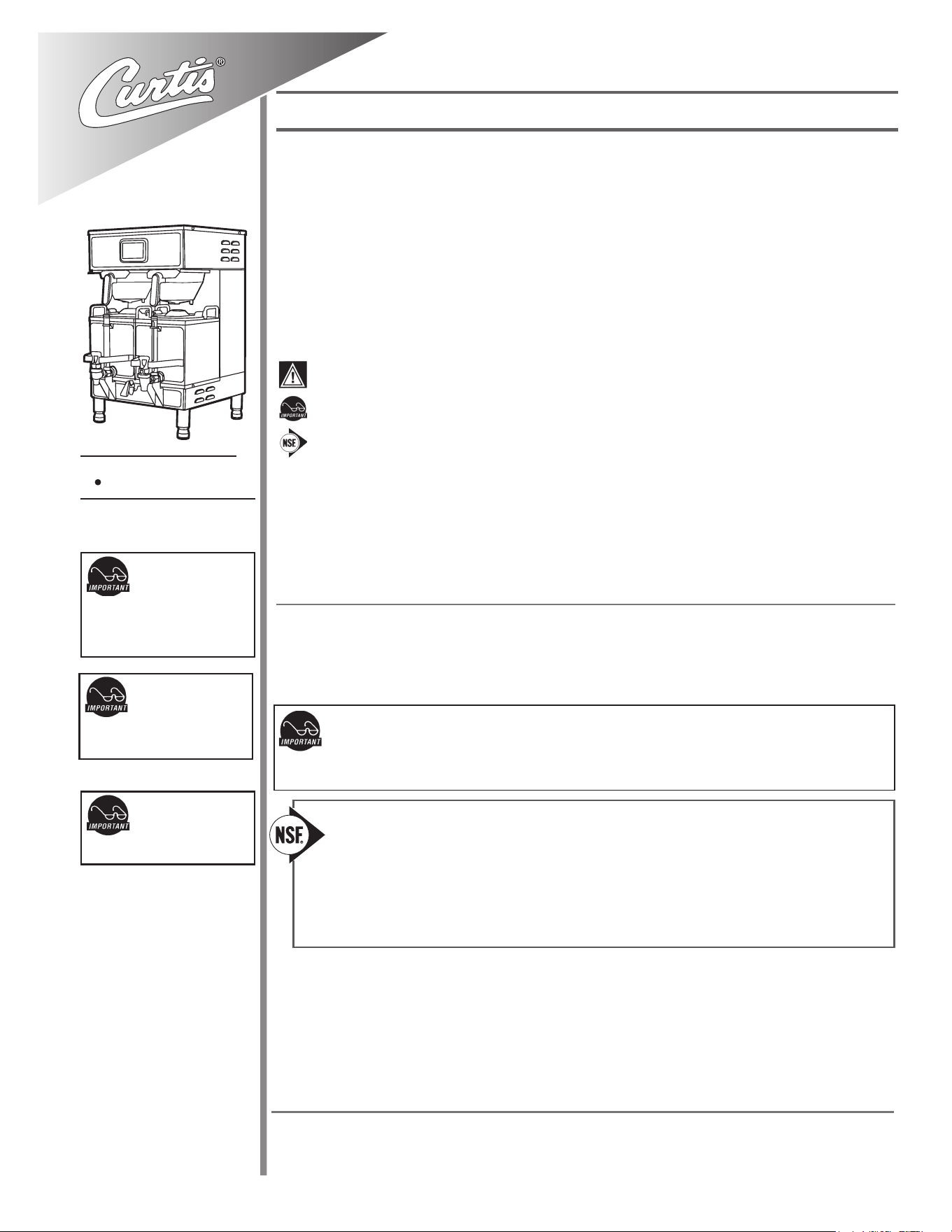
SETUP STEPS
1.Theunitshouldbelevel(lefttoright-fronttoback),onasecuresurface.
2. Connectthewaterlinetothewaterinletttingontherearoftheunit.Watervolumeowtothemachine
shouldbeconsistent.Usetubingsizedsufcientlytoprovideaminimumowrateofonegallonperminute.
2
1.BrewershouldbeON(Conrmatthereartoggleswitch).TheLCDscreenshouldreadReadytoBrew.
2.Placeanemptysatelliteserveronthewarmerdeck,underthebrewconeandtouchthewarmericontoPreheatthesatellite.
6. Touch desired
brew button.
Brewing will begin
immediately.
5. Transfer lled
brewcone to
brewer.
3. Place a clean lter
into the brewcone.
4. Fill brewcone with
ground coffee.
COFFEE BREWING INSTRUCTIONS
WARNINGTOAVOIDSCALDING,Donotremovebrewconewhilebrewlightisashing.
Touch Screen Control Module
The touch screen turns on when power is available to the controller. The screen will contain standard control feature such as symbols and but-
tons.Pressingtheseelementswithyourngertipwillactivatetheprogrammingfunctions.Thedefaultscreen,aswellassomeaddedcontrol
buttons are shown in the illustration below.
STATUS LIGHTS
BREW BUTTONS
CURTIS LOGO
TO ENTER PROGRAMMING
Tap Curtis logo 5 times to bring
up the ACCESS CODE screen.
RETURN TO HOME SCROLL RETURN TO PREVIOUS
UNDO
WARMERS
CONTROL SYMBOLS
All of these symbols may not be
visible at one time.
Your Curtis G4/Gold Cup Series is Factory Pre-Set for Optimum Performance.
After connection to water and power; turn on the brewer at the rear toggle switch. You will hear a beep and the status lights will come on for a moment.
The screen will display . Next is displayed. Water will ll the tank (2-3 minutes depending on water ow rate).
When the proper level is reached will appear on the screen. It takes approximately 30 minutes to reach the set point temperature.
Control will display when temperature reaches the set point. The unit is now ready to brew.
MODEL NUMBER
CONTROL BD NUMBER
READY TO BREW
HEATING
FILLING
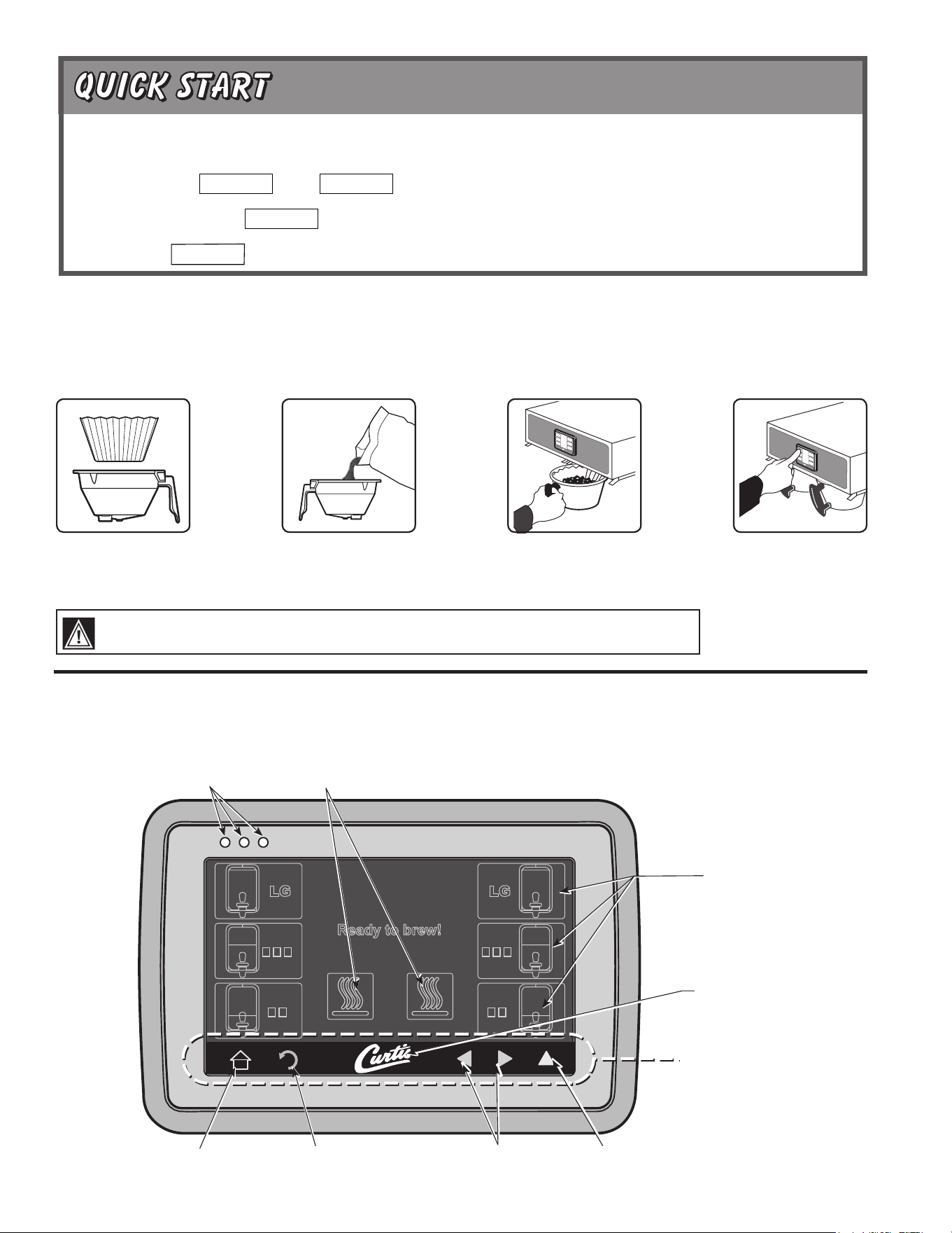
3
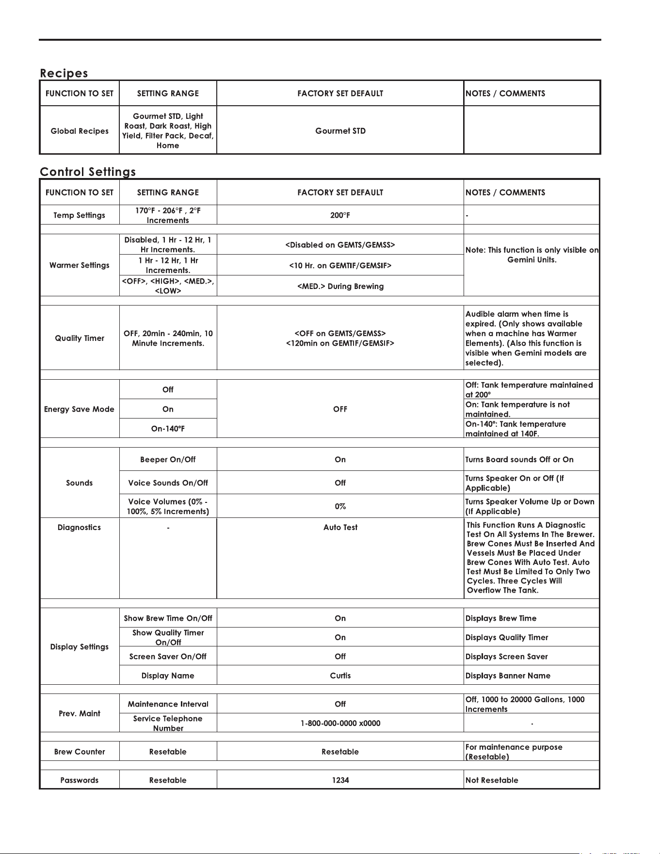
MAIN MENU screen
contains ve contol
icons: RECIPES,
CONTROL SETTINGS,
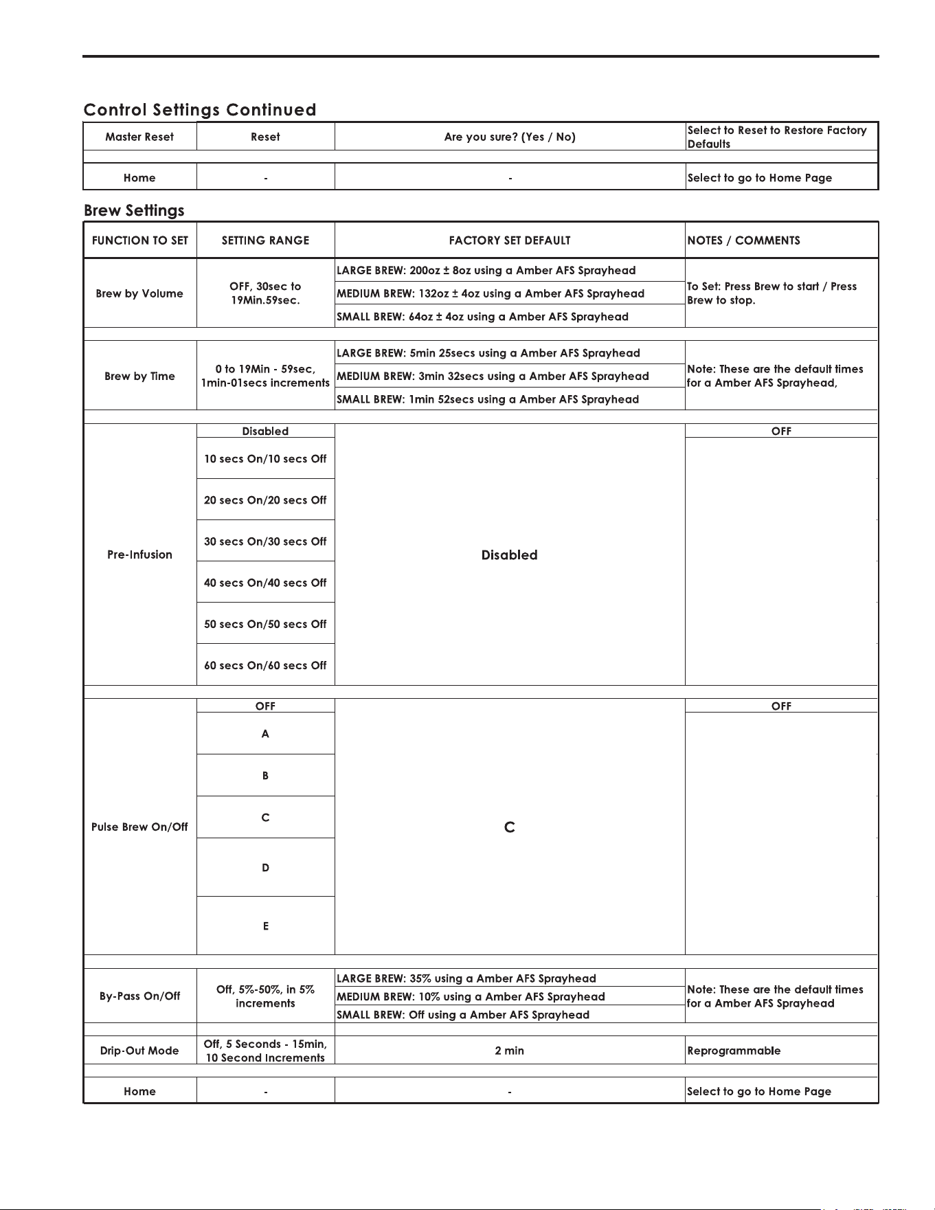
BREW SETTINGS,
MODEL SELECT and
EXIT.
ACCESS CODE
screen. Default is 1
2 3 4. Once the code
is entered, press
OK. The Main Menu
screen will appear.
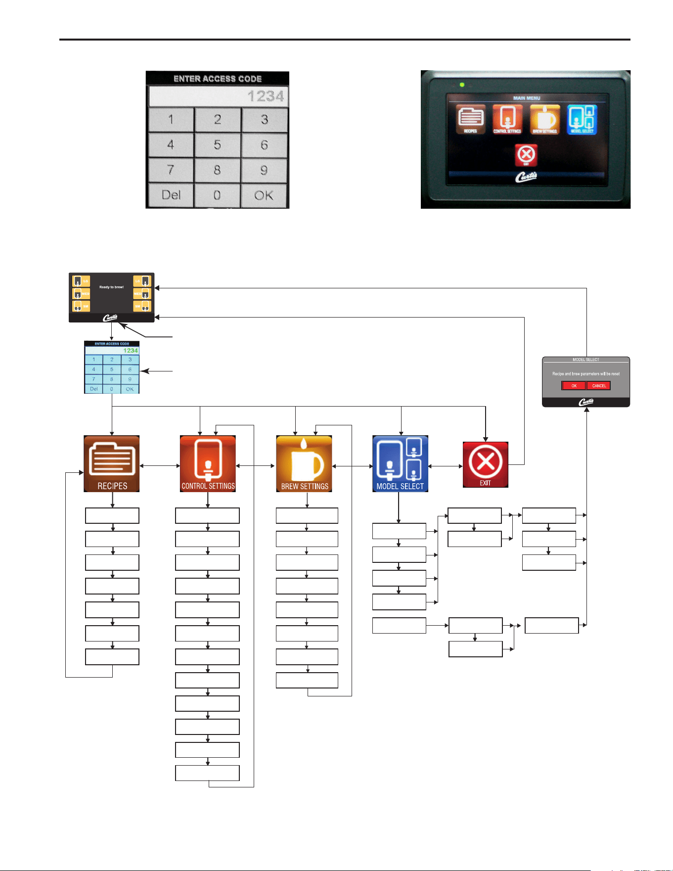
Menu Tree
ThischartexplainshowtoentertheprogrammodeandmenuselectionsavailablefromtheMAINMENU.
PROGRAMMING
Tap "Curtis" Logo 5 Times
to Enter Programming Mode
Enter 1-2-3-4 to access the Main Menu
…nottuB tceleS
sgnitteS pmeTDTS temruoG
hctaB enO
elgniS
Gemini
emuloV yB werBsgnitteS remraWtsaoR thgiL hctaB owTniwT
Gemini IF
emiT yB werBremiT ytilauQtsaoR kraD Three Batch
Thermopro
noisufnI-erPgnivaS ygrenE
dleiY hgiH
Milano
ffO/nO werB esluP
sdnuoSkcaP retliF
hctaB eerhT
puC cimareC
puC elgniS
ffO/nO ssapyBscitsongaiDfaceD
Paper Cup
tuO pirD
sgnitteS yalpsiD
emoH
emoHtniaM - verP
Brew Counter
Passwords
Master Rese t
Home
4
Menu Features
5
Menu Features

6
System Fault Messages
Component Failure
Service Required
1-(800)-000-0000x
Maintenance Required
Service Required
1-(800)-000-0000x
Brew count "Gallons Since Reset" exceeds
programmed Preventative Maintenance period
Lime Scale Warning
Service Required
1-(800)-000-0000x
Scale Starting to Build Up
Water Level Probe
Water level probe resistance above warning
threshold (test value 23k Ohm)
Low Water Flow Warning
Service Required
1-(800)-000-0000x
If the Inlet valve remains on longer than 40
Seconds (during the brew cycle only) and repeats
TWICE during that brew cycle. It shall clear upon
the next brew and if the same low flow exists
again, it will re-appear.
Water Level Error
Service Required
1-(800)-000-0000x
The fill solenoid has either run for more than 10
minutes on the initial tank fill or 1.5 minutes in
normal operation
Sensor Error
Service Required
1-(800)-000-0000x
Break in the temperature thermistor circuit or short
curcuit.
Over Temp. Error
Service Required
1-(800)-000-0000x
The sensor is reading that temperature in the
heating tank has risen above 210ºF, or sensor has
shorted to ground.
Lime Scale Error
Service Required
1-(800)-000-0000x
Probe
Water level probe resistance above error threshold
(test value 180kOhm)
Internal Error 1
Service Required
1-(800)-000-0000x
ERROR MESSAGES - STOPS BREWING
WARNING MESSAGES - ALLOWS BREWING
MESSAGE DISPLAY ERROR DESCRIPTION CAUSE
MESSAGE DISPLAY WARNING DESCRIPTION CAUSE
A Component has Failed
Maintenance Required
Low Water Flow
Open Sensor
Excess Temperature
Break in the UPM-UCM Communication circuit.UPM-UCM Communication
Fill run error / Overflow
Current in one of the components is not within normal
range.
7
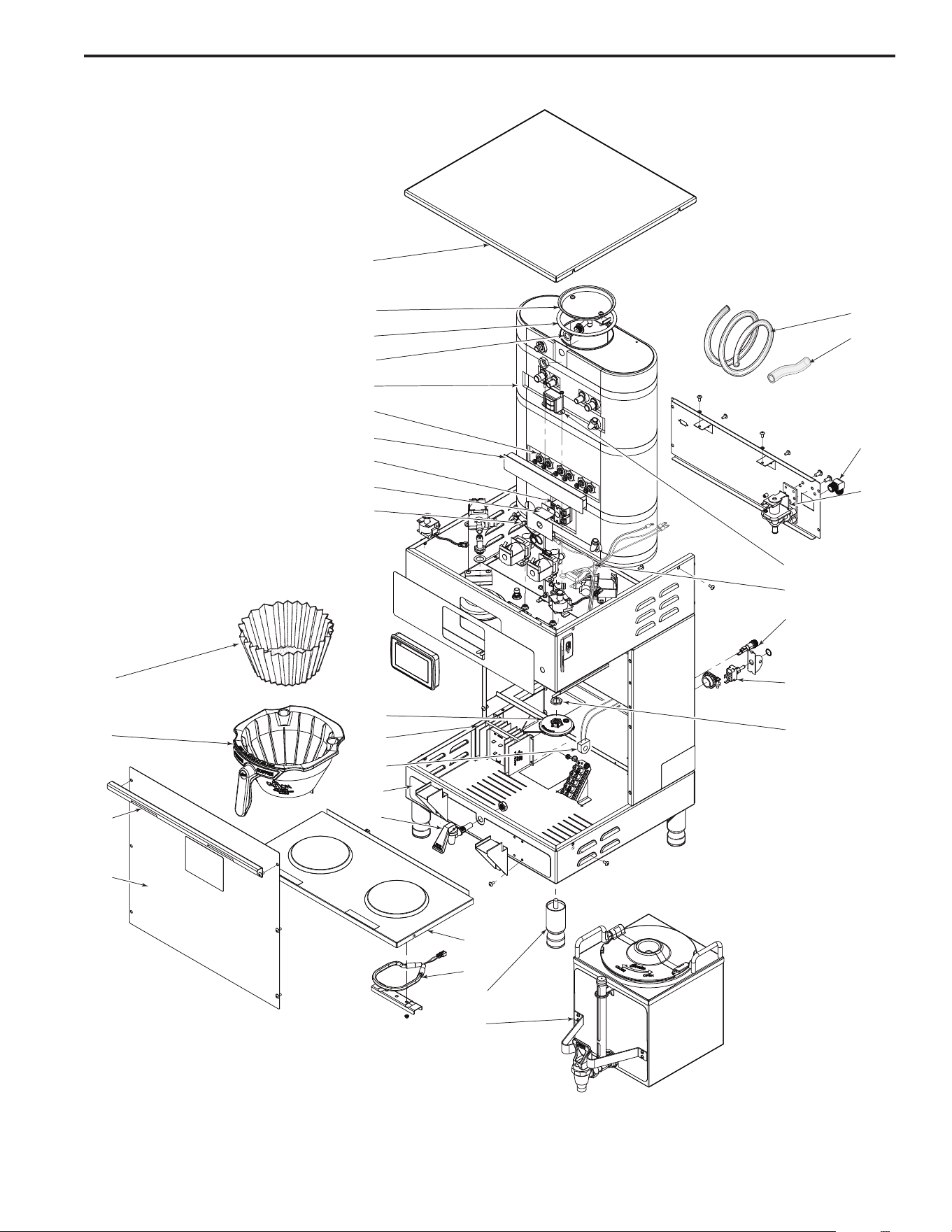
Illustrated Parts
Main View
1
2
3
4
5
6
7
8
9
10
16
17
18
19
11
12
13
14
15
24
25
26
27
28
29
30
31
32
20
21
22
23
8
1.000"
.
.1"
.
1.1"
.0
."
.
.0"
1.1
."
1.
.000"
10.1
11.0"
.
11.000"
.
10."
.
10."
.
.0"
.
."
1.0
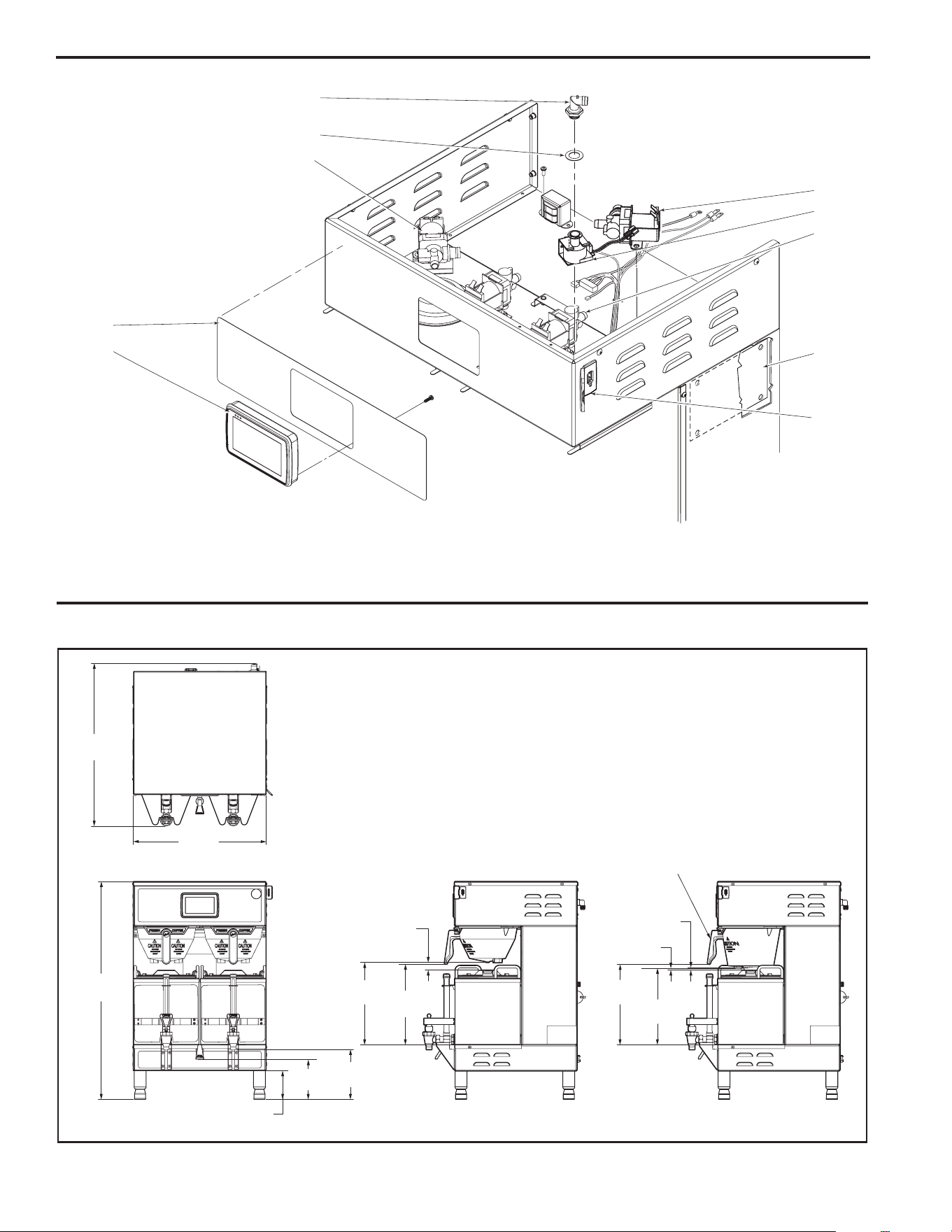
Illustrated Parts
Top Wrap
Rough-In Drawing
38
39
36
37
35
33
34
40
41
42

9
Parts List
ITEM NO. PART NO. DESCRIPTION
1 WC-5421-BLK COVER, TOP - PAINTED BLACK TEXTURE PC
1A WC-5421 COVER, TOP STAINLESS GEMTIF
2 WC-37008 KIT, TANK LID ROUND
3 WC-43067* O-RING, 4-1/2 I.D. x Ø.285 C.S. SILICONE
4 WC-37406* KIT, FAIL SAFE PROBE NON-METALLIC ROD
5 WC-62033 TANK COMPLETE, GEMTS WITH ULTEM FITTINGS
6 WC- 934-04* KIT, HEATING ELEMENT 2.5KW 220V W/JAM NUT & SILICONE WASHERS
7 WC-4382* GUARD, SHOCK - DOUBLE HEATING ELEMENTS
8 WC- 522* THERMOSTAT, HI LIMIT HEATER DPST 277V-40A
9 WC-43055 GUARD, SHOCK RESET THERMOSTAT
10 WC-1438-101* SENSOR, TEMPERATURE TANK
11 WC-29050* SPRAYHEAD ASSY, AFS-AMBER
12 WC-8559* RELAY, SOLID STATE 40A w/INTEGRATED HEATSINK
13 WC-14045-101 CURRENT SENSOR ASSY G4
14 WC-39745 LABEL, BOTTOM WRAP - GEMTIF
15 WC-1809 FAUCET, PS/HSP SERIES HOT WATER 1/2-20 UNF
16 GEM-6* FILTER, 500PK GEM-12/230A
17 WC-37308 KIT, BREW CONE GEMINI NON-METAL with “FRESH COFFEE” LOGO
18 WC-37310 KIT, BREWCONE ALIGNMENT BRACKET STAINLESS
19 WC-61309 COVER, FRONT CENTER WRAP W/A STAINLESS GEMTIF
20 WC-61301 DECK, WARMER WELD ASSEMBLY GEMTIF
21 WC-37102* KIT, WARMER ELEMENT
22 WC-3528 LEG, 4” ADJUSTABLE 3/8-16 THRD STYLIZED
23 GEM-3 SATELLITE SERVER, 1-1/2 GAL.
24 WC-5310* TUBE, 5/16 ID x 1/8W SILICONE
25 WC-5350* TUBE, SILICONE Ø1/2” ID x Ø3/4” OD x 1/8” WALL
26 WC-2402P ELBOW, 3/8 NPT x 3/8 FLARE PLATED
27 WC- 847* VALVE, INLET 2 GPM 120V-10W
28 WC- 589-101 TRANSFORMER, 120/230VAC - 24VAC 4.8VA w/LEADS & TERMINALS
29 WC-13450 HARNESS ASSY, COMPLETE TP2T10G4/GEMTS10G4/GEMTIF10G4
30 WC-1501 FUSE, HOLDER ASSY w/5A FUSE
31 WC- 102 * SWITCH, TOGGLE SPST 15A 125Vac RESISTIVE
32 WC-4212-02 NUT, 5/8-18 JAM PLASTIC-ULTEM
33 WC-37121 KIT, DUMP VALVE LEFT
34 WC- 442 * SOLENOID, LOCK BREW CONE RIGHT 120VAC
35 WC-2977-101 FITTING, SPRAYHEAD ULTEM
36 WC-43089* GASKET, 1.00”OD x .625” I.D. x .030” THK RED SILICONE 40 SHORE
37 WC-37122* KIT, DUMP VALVE RIGHT
38 WC-39812 LABEL, OUTER TOUCHSCREEN GEMTSG4 CURTIS LOGO
39 WC-10000* CONTROL MODULE, TOUCH SCREEN G4
40 WC- 844-101* VALVE, BYPASS 120V-14W NON ADJUSTABLE WITH RESTRICTOR (WC-2945)
41 WC-10001* UNIVERSAL POWER MODULE - G4
42 WC-10008 UNIVERSAL HOST ADAPTER (USB)
* RECOMMENDED PARTS TO STOCK
10
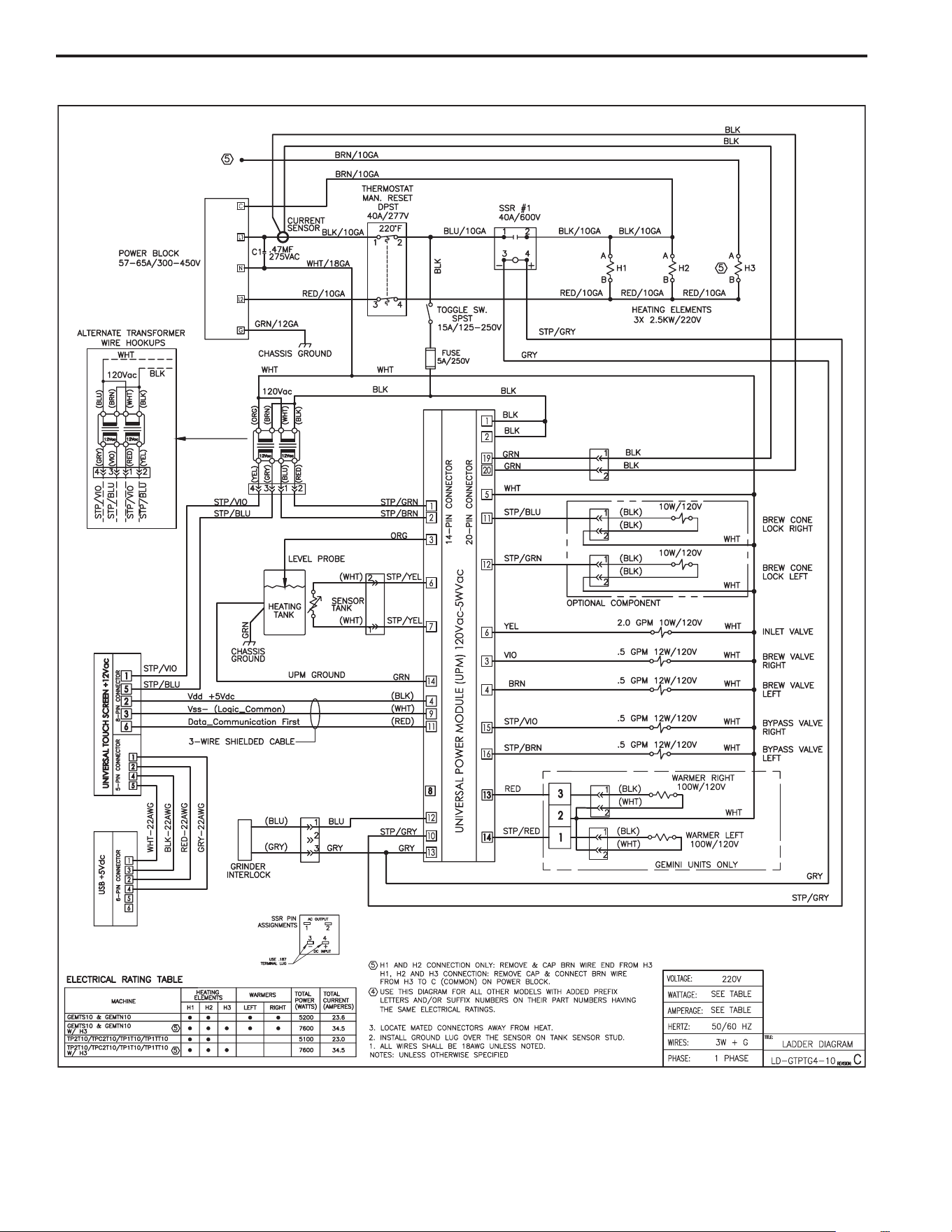
Electrical Schematic

11
Cleaning the Satellite Server
To clean the Satellite components, prepare a mild solution of detergent and warm water..
1. Remove lid from Satellite. Clean the lid at the funnel area with a spiral brush and detergent solution.
2. Rinse the lid, removing all traces of cleaning solution.
3. Unscrew the handle/bonnet assembly and remove it from the dispensing faucet.
4. Pull the silicone seat cup from faucet stem and inspect it for wear, cracks, or hardening. Replace the seat cup
if necessary.
5. Clean all parts. Thoroughly rinse with clear warm water.
6. Dry and assemble the handle/bonnet parts. Hand-tighten the assembly onto the faucet.
7. Remove the gauge glass tube by unscrewing the gauge glass cap.
8. Clean the gauge glass tube and the two washers with a gauge brush and detergent solution. Rinse with clear
water. Dry the parts and assemble them onto the Satellite.
DO NOT immerse the Satellite in water or any other liquid.
9. Clean inside of the Satellite. Remove coffee residue with the detergent solution.
10. Thoroughly rinse out the Satellite with clear warm water.
Cleaning the Coffee Brewer
Regular cleaning and preventive maintenance is essential in keeping your coffee brewer looking and working like new.
CAUTION – Do not use cleansers, bleach liquids, powders or any other substance containing chlorine. These
products promote corrosion and will pit the stainless steel. USE OF THESE PRODUCTS WILL VOID THE
WARRANTY.
1. Wipe exterior surfaces with a moist cloth, removing spills and debris.
2. Slide the brewcone out and clean it. Clean the sprayhead area with a moist clean cloth.
3. Rinse and dry the brewcone.
4. Drain drip tray of coffee. Wash out the drip tray. Dry the tray.
5. Rub a stainless steel polish on the outside surfaces to protect the brewer.

Product Warranty Information
TheWilburCurtisCompanycertiesthatitsproductsarefreefromdefectsinmaterialandworkmanshipundernormaluse.Thefollowinglimited
warranties and conditions apply:
3 Years,PartsandLabor,fromOriginalDateofPurchaseondigitalcontrolboards.
2 Years,Parts,fromOriginalDateofPurchaseonallotherelectricalcomponents,ttingsandtubing.
1 Year,Labor,fromOriginalDateofPurchaseonallelectricalcomponents,ttingsandtubing.
Additionally,theWilburCurtisCompanywarrantsitsGrindingBurrsforForty(40)monthsfromdateofpurchaseor40,000poundsofcoffee,
whichevercomesrst.StainlessSteelcomponentsarewarrantedfortwo(2)yearsfromdateofpurchaseagainstleakingorpittingandreplace-
ment parts are warranted for ninety (90) days from date of purchase or for the remainder of the limited warranty period of the equipment in which
the component is installed.
Allin-warrantyservicecallsmusthavepriorauthorization.ForAuthorization,calltheTechnicalSupportDepartmentat1-800-995-0417.Effective
dateofthispolicyisApril1,2003.
Additional conditions may apply. Go to www.wilburcurtis.com to view the full product warranty information.
CONDITIONS & EXCEPTIONS
Thewarrantycoversoriginalequipmentattimeofpurchaseonly.TheWilburCurtisCompany,Inc.,assumesnoresponsibilityforsubstitutereplace-
ment parts installed on Curtis equipment that have not been purchased from the
WilburCurtisCompany,Inc.TheWilburCurtisCompanywillnotacceptanyresponsibilityifthefollowingconditionsarenotmet.Thewarranty
does not cover and is void under the following circumstances:
1) Improper operation of equipment: The equipment must be used for its designed and intended purpose and function.
2) Improper installation of equipment: This equipment must be installed by a professional technician and must comply with all local electrical,
mechanical and plumbing codes.
3) Improper voltage: Equipment must be installed at the voltage stated on the serial plate supplied with this equipment.
4) Improper water supply: This includes, but is not limited to, excessive or low water pressure, and inadequate or uctuating water ow
rate.
5) Adjustments and cleaning: The resetting of safety thermostats and circuit breakers, programming and temperature adjustments are the
responsibility of the equipment owner. The owner is responsible for proper cleaning and regular maintenance of this equipment.
6) Damaged in transit: Equipment damaged in transit is the responsibility of the freight company and a claim should be made with the car-
rier.
7) Abuse or neglect (including failure to periodically clean or remove lime accumulations): Manufacturer is not responsible for variation
in equipment operation due to excessive lime or local water conditions. The equipment must be maintained according to the manufacturer’s
recommendations.
8) Replacement of items subject to normal use and wear: This shall include, but is not limited to, light bulbs, shear disks, “0” rings, gaskets,
silicone tube, canister assemblies, whipper chambers and plates, mixing bowls, agitation assemblies and whipper propellers.
9) Repairs and/or Replacements are subject to our decision that the workmanship or parts were faulty and the defects showed up under normal
use. All labor shall be performed during regular working hours. Overtime charges are the responsibility of the owner. Charges incurred by
delays, waiting time, or operating restrictions that hinder the service technician’s ability to perform service is the responsibility of the owner
of the equipment. This includes institutional and correctional facilities. The Wilbur Curtis Company will allow up to 100 miles, round trip, per
in-warranty service call.
RETURN MERCHANDISE AUTHORIZATION: All claims under this warranty must be submitted to the Wilbur Curtis Company Technical
Support Department prior to performing any repair work or return of this equipment to the factory. All returned equipment must be repackaged
properly in the original carton. No units will be accepted if they are damaged in transit due to improper packaging. NO UNITS OR PARTS WILL
BE ACCEPTED WITHOUT A RETURN MERCHANDISE AUTHORIZATION (RMA). RMA NUMBER MUST BE MARKED ON THE CARTON
OR SHIPPING LABEL. All in-warranty service calls must be performed by an authorized service agent. Call the Wilbur Curtis Technical Sup-
portDepartmenttondanagentnearyou.
7/11 . F-3804 rev NC
WILBUR CURTIS CO., INC.
6913 Acco St., Montebello, CA 90640-5403 USA
Phone: 800/421-6150 Fax: 323-837-2410
Web Site: www.wilburcurtis.com
7/6/[email protected] . EDR 7842