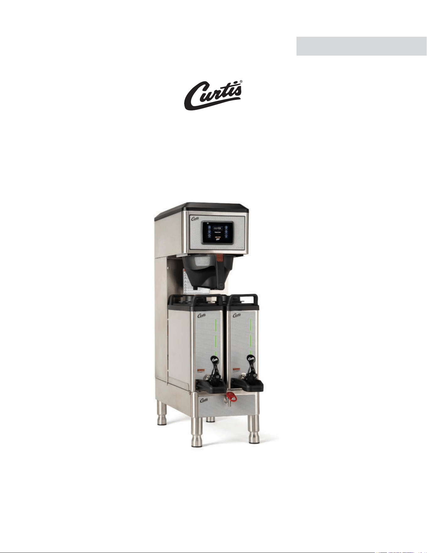
G4 GEMXN IntelliFresh
®
Coffee Brewing System
USER GUIDE
READ AND SAVE THESE INSTRUCTIONS
NOTICE TO INSTALLER: Please leave this booklet with the machine.
Style varies. Model G4GEMXNXXXSIFT shown.
ø øø ø ø 111120A
FC125 - G4GEMXN, FRONT COVER F-10124 revNC

CONTENTS CL123
.H\)HDWXUHV6SHFLÀFDWLRQV6\VWHP5HTXLUHPHQWV............................................................................................FS109
,PSRUWDQW6DIHJXDUGV ...............................................................................................................................................IS2
,QVWDOODWLRQ,QVWUXFWLRQV*HQHUDO ...............................................................................................................................II2
,QVWDOODWLRQ,QVWUXFWLRQV/HYHOLQJ:DWHU6XSSO\(OHFWULFDO ....................................................................................II14
2SHUDWLQJ,QVWUXFWLRQV ............................................................................................................................................OI65
,QWHOOL)UHVK
®
Features ............................................................................................................................................... IF2
&OHDQLQJ,QVWUXFWLRQV%UHZHU .................................................................................................................................CI1
&OHDQLQJ,QVWUXFWLRQV'LVSHQVHU ..........................................................................................................................CI29
3URJUDPPLQJ*XLGH ............................................................................................................................................... 3*
5RXJK,Q'UDZLQJ............................................................................................................................................... 5'
5RXJK,Q'UDZLQJ'LVSHQVHU ........................................................................................................................... 5'
,OOXVWUDWHG3DUWV5HFRPPHQGHG3DUWV .................................................................................................................. IP198
,OOXVWUDWHG3DUWV5HFRPPHQGHG3DUWV7DQN$VVHPEO\ ........................................................................................ IP32
(OHFWULFDO6FKHPDWLF0DLQ&KDVVLV ...................................................................................................................ES152
(OHFWULFDO6FKHPDWLF'LVSHQVHU.........................................................................................................................ES108
7URXEOHVKRRWLQJ*XLGH*HQHUDO ............................................................................................................................7*
7URXEOHVKRRWLQJ*XLGH665&LUFXLW ......................................................................................................................7*
7URXEOHVKRRWLQJ*XLGH,QWHOOLIUHVK&LUFXLW ...........................................................................................................7*
7URXEOHVKRRWLQJ*XLGH'LDJQRVWLFV ....................................................................................................................7*
(UURU&RGHV .............................................................................................................................................................EC1
3URGXFW:DUUDQW\....................................................................................................................................................3:
Contact Information
Wilbur Curtis Co., Inc.
6913 Acco Street | Montebello, CA 90640 US
Phone: 323-837-2300 | Toll Free: 800-421-6150
Email: [email protected] | Web: www.wilburcurtis.com
'PSUIFMBUFTUTQFDJmDBUJPOTBOEJOGPSNBUJPOHPUPXXXXJMCVSDVSUJTDPN
5PMM'SFF].POEBZ'SJEBZA.M. - 4:00 P.M. PT
Email: [email protected]
%VFUPDPOUJOVFEQSPEVDUJNQSPWFNFOUUIFQSPEVDUTJMMVTUSBUFEQIPUPHSBQIFEJOUIJTHVJEFNBZWBSZTMJHIUMZGSPNUIFBDUVBMQSPEVDU
((&.9/$0/5&/54-*45øø 040620NC

KEY FEATURES/SPECIFICATIONS/SYSTEM REQUIREMENTS FS109
Key Features
• Generation Four (G4) Digital Control Module – provides precise control over all aspects of brewing: time,
temperature, volume plus specialty coffee needs from pre-infusion to pulse-brewing to water bypass. Large,
4.3” touch screen with icon-driven interface, streamlines operation. On-screen instructions provide fast,
intuitive training; reduces service calls.
• Built-in Self Diagnostic System – Includes real-time feedback of the brewing process and energy saving mode.
• Field selectable for 0.5, 1.0 or 1.5 gal. (1.9, 3.8 or 5.7 liter) batch brewing.
• IntelliFresh
®
Technology – Temperature and time information follow the dispensers.
• -&%OPUJmDBUJPOPGGSFTIOFTTUJNJOH
• Industry’s most effective mineral tolerant design.
6SHFLÀFDWLRQV6HOHFWHG0RGHOV
(OHFWULFDO6XSSO\5HTXLUHPHQWV
02'(/ '(6&5,37,21 3+$6( 92/76 $036
+($7,1*
&21),*
:,5( :$776 +(57= &$3$&,7<
**(0;1$ Single, 1.5 Gal. with IntelliFresh 1 PH 120/220 V 13.5/13.5 A 2 X 1600 W 2W/3W + G 1650/2800 W 50/60 Hz
4.5/10.0 gal./hr.
[17.0/37.9 L/hr]
'LPHQVLRQV :DWHU6XSSO\5HTXLUHPHQWV
02'(/ +(,*+7 :,'7+ '(37+ 6+,3:(,*+7 6+,3&8%( :$7(5&211(&725 :$7(535(6685( 0,1)/2:5$7(
**(0;1$
31.87”
[81.0 cm]
10.50”
[26.7 cm]
26.44”
[67.2 cm]
51.0 lbs
[23.1 kg]
7.0 cu. ft.
[0.20 m
3
]
µÁDUH
20 - 90 psi
[138 - 620 kPa]
1.0 gpm
[3.8 Lpm]
G4GEMXN, KEY FEATURES/SPECS/SYSTEM REQUIREMENTS 042920NC
Following are the factory default settings for the IntelliFresh brewer:
• Energy Save Mode = Off
• Quality Timer = 120 Minutes
• Warmer Auto-Off = 18 Hours
• Brew Temperature = 200°F (92°C)
• Water Bypass = On LARGE and MEDIUM brew only
• Brew Volume = Large-Medium-Small
IMPORTANT SAFEGUARDS IS2
Symbols
This is the safety alert symbol. It is used to alert you to potential physical injury hazards. Obey all safety
messages that follow this symbol to avoid possible injury or death.
DANGER - Indicates a hazardous situation which, if not avoided, will result in death or serious injury.
WARNING - Indicates a hazardous situation which, if not avoided, could result in death or serious injury.
CAUTION - Indicates a hazardous situation which, if not avoided, could result in minor or moderate injury.
NOTICE - Indicates a situation which, if not avoided, could result in property damage.
IMPORTANT - Provides information and tips for proper operation.
SANITATION REQUIREMENTS
Important Safeguards/Conventions
WARNING:
• Make sure that this appliance is installed and grounded according to the INSTALLATION
*/4536$5*0/4CZRVBMJmFEQFSTPOOFMCFGPSFBUUFNQUJOHUPVTFJU'BJMVSFUPGPMMPXUIF*/45"--"5*0/
INSTRUCTIONS could result in personal injury or void the warranty.
• This appliance is designed for commercial use. Any service other than cleaning and preventive
maintenance should be performed by an authorized Wilbur Curtis service technician.
• 5PSFEVDFUIFSJTLPGmSFPSFMFDUSJDTIPDL%0/05PQFOUIFTFSWJDFQBOFMT5IFSFBSFOPVTFS
serviceable parts inside.
• Keep hands, arms and other items away from hot surfaces of the unit during operation.
• Clean the appliance and any dispensers completelyCFGPSFVTJOHUIFNGPSUIFmSTUUJNFBDDPSEJOHUP
the CLEANING INSTRUCTIONS. Clean them regularly as instructed in the CLEANING INSTRUCTIONS.
• Use this appliance only for its intended use, brewing/dispensing hot and/or cold beverages/water.
• This appliance is not intended for use by persons (including children) with reduced physical, sensory
or mental capabilities or lack of experience and knowledge, unless they have been given supervision
or instruction concerning use of the appliance by a person responsible for their safety. Children should
be supervised to ensure that they do not play with the appliance.
• Avoid spillage onto the power (mains) connector.
$0''&&5&"#3&8&34*.1035"/54"'&(6"3%44:.#0-4 )
WARNING - 5IJTQSPEVDUDBOFYQPTFZPVUPDIFNJDBMTJODMVEJOH"DSZMBNJEFBOE#JTQIFOPM"#1"
which are known to the State of California to cause cancer and birth defects or other reproductive harm.
'PSNPSFJOGPSNBUJPOWJTJUXXX18BSOJOHTDBHPW

IMPORTANT SAFEGUARDS IS2
$0''&&5&"#3&8&34*.1035"/54"'&(6"3%44:.#0-4 )
CE Requirements
• This appliance must be installed in locations where it can be overseen by trained personnel.
• 'PSQSPQFSPQFSBUJPOUIJTBQQMJBODFNVTUCFJOTUBMMFEXIFSFUIFUFNQFSBUVSFJTCFUXFFO¡$UP¡$
• This appliance is not suitable for outdoor use.
• 5IJTBQQMJBODFTIBMMOPUCFUJMUFENPSFUIBO¡GPSTBGFPQFSBUJPO
• "OFMFDUSJDJBONVTUQSPWJEFFMFDUSJDBMTFSWJDFBTTQFDJmFEJODPOGPSNBODFXJUIBMMMPDBMBOEOBUJPOBMDPEFT
'PSTBGFVTFBOBMMQPMFEJTDPOOFDUJPONVTUCFJODPSQPSBUFEJOUPUIFmYFEXJSJOHJOBDDPSEBODFXJUIUIF
XJSJOHSVMFTPVUMJOFEJODMBVTFPG*&$GPSNFFUJOHUIFNJOJNVNFMFDUSJDBMTBGFUZPGUIJTTUBOEBSE
• This appliance must not be cleaned by water jet.
• 5IJTBQQMJBODFDBOCFVTFECZQFSTPOTBHFEGSPNZFBSTBOEBCPWFJGUIFZIBWFCFFOHJWFOTVQFSWJTJPOPS
instruction concerning use of the appliance in a safe way and if they understand the hazards involved.
• ,FFQUIFBQQMJBODFBOEJUTDPSEPVUPGSFBDIPGDIJMESFOBHFEMFTTUIBOZFBST
• "QQMJBODFTDBOCFVTFECZQFSTPOTZFBSTBOEBCPWFXJUISFEVDFEQIZTJDBMTFOTPSZPSNFOUBMDBQBCJMJUJFT
or lack of experience and knowledge if they have been given supervision or instruction concerning use of the
appliance in a safe way and understand the hazards involved.
• $IJMESFOVOEFSUIFBHFPGZFBSTTIPVMECFTVQFSWJTFEUPFOTVSFUIFZEPOPUQMBZXJUIUIFBQQMJBODF
• If the power cord is ever damaged, it must be replaced by the manufacturer or authorized service personnel
with a special cord available from the manufacturer or its authorized service personnel in order to avoid a
hazard.
• Machine must not be immersed for cleaning.
• $MFBOJOHBOEVTFSNBJOUFOBODFTIBMMOPUCFNBEFCZDIJMESFOVOMFTTUIFZBSFPMEFSUIBOZFBSTBOE
supervised.
• This appliance is intended to be used in household and similar applications such as:
oTUBGGLJUDIFOBSFBTJOTIPQTPGmDFTBOEPUIFSXPSLJOHFOWJSPONFOUT
oCZDMJFOUTJOIPUFMTNPUFMTBOEPUIFSSFTJEFOUJBMUZQFFOWJSPONFOUT
– bed and breakfast type environments.
• This appliance not intended to be used in applications such as:
– farm houses
• Access to the service areas permitted by Authorized Service personnel only.
• 5IF"8FJHIUFETPVOEQSFTTVSFMFWFMJTCFMPXE#"

INSTALLATION INSTRUCTIONS II2
Installation Instructions
Installation Requirements
• A secure surface capable of supporting the weight of the appliance.
• For units without an attached cord set attached or dual voltage units set up for use with 220 - 240 Volts:
"QQSPQSJBUFMZTJ[FE6-MJTUFEHSPVOEJOHUZQFQPXFSDBCMFUPNFFUUIFFMFDUSJDBMTQFDJmDBUJPOTGPSUIF
BQQMJBODF*GZPVIBWFRVFTUJPOTBCPVUUIFDPSSFDUDBCMFTJ[FBOEMFOHUIDPOTVMUBRVBMJmFEJOTUBMMFS*GUIF
appliance will be hard wired to a junction box, the power cable must be long enough so that the unit can be
moved for cleaning underneath.
• "HSPVOEFEFMFDUSJDBMDPOOFDUJPOUPBOFMFDUSJDBMDJSDVJUUIBUNFFUTUIFFMFDUSJDBMTQFDJmDBUJPOTPGUIF
appliance (see SPECIFICATIONS). The circuit must be protected by the appropriate sized circuit breaker. If
you are not certain that the existing circuit meets the requirements for your unit, consult a licensed electrician.
• "XBUFSmMUSBUJPOTZTUFNJTSFRVJSFEUPNBJOUBJOUSPVCMFGSFFPQFSBUJPO8JMCVS$VSUJT$P*ODSFDPNNFOETB
8JMCVS$VSUJTBQQSPWFEXBUFSmMUFS4FFUIF$VSUJT&RVJQNFOU$BUBMPHGPSBGVMMMJOFPG8JMCVS$VSUJTBQQSPWFE
XBUFSmMUFST
• 1PUBCMFXBUFSTVQQMZMJOFDPOOFDUJPOGSPNUIFXBUFSmMUFSDBQBCMFPGTVQQMZJOHUIFNJOJNVNnPXSBUFSFRVJSFE
CZUIFTQFDJmDBUJPOT5IFXBUFSTVQQMZMJOFNVTUCFBCMFUPDPOOFDUUPUIFnBSFmUUJOHPOUIFCBDLPGUIF
VOJU4FFUIFSPECIFICATIONS section for the correct size. The water line should also be capable of being
controlled by a shut off valve. Do not connect the water line to a saddle valve or needle valve.
*&$SFRVJSFTUIFGPMMPXJOHXBUFSDPOOFDUJPO
1 A quick disconnect or additional coiled tubing (at least two times the depth of the appliance) is required
so that it can be moved for cleaning underneath.
2 5IJTFRVJQNFOUJTUPCFJOTUBMMFEXJUIBEFRVBUFCBDLnPXQSPUFDUJPOUPDPNQMZXJUIBQQMJDBCMF
federal, state and local codes.
8BUFSQJQFDPOOFDUJPOTBOEmYUVSFTEJSFDUMZDPOOFDUFEUPBQPUBCMFXBUFSTVQQMZTIBMMCFTJ[FE
installed and maintained in accordance with federal, state and local codes.
WARNING:*OTUBMMBUJPOJTUPCFQFSGPSNFEPOMZCZBRVBMJmFEJOTUBMMFS
WARNING: Improper electrical connection may result in an electric shock hazard or damage the unit. This
appliance must be properly grounded.
NOTICE: DO NOT connect this appliance to a hot water supply. The water inlet valve is not rated for hot
water. Do not exceed the maximum water pressure stated in the SPECIFICATIONS section.
IMPORTANT: Observe all governing codes and ordinances.
#3&8&34=41&$*"-5:%*41&/4&34(&/&3*$*/45"--"5*0/*/4536$5*0/4 F
5IF*OUFSOBUJPOBM1MVNCJOH$PEFPGUIF*OUFSOBUJPOBM$PEF$PVODJMBOEUIF'PPEBOE%SVH"ENJOJTUSBUJPO
'%"'PPE$PEFNBOVBMEJSFDUUIBUUIJTFRVJQNFOUNVTUCFJOTUBMMFEXJUIBEFRVBUFCBDLnPX
QSFWFOUJPOJODPNQMJBODFXJUIGFEFSBMTUBUFBOEMPDBMDPEFT'PSVOJUTJOTUBMMFEPVUTJEFPGUIF64"
make sure that the installation is in compliance with the applicable plumbing/sanitation code for your area.
Setting Up 120/220 Volt Units for 220-240 Volt
Operation
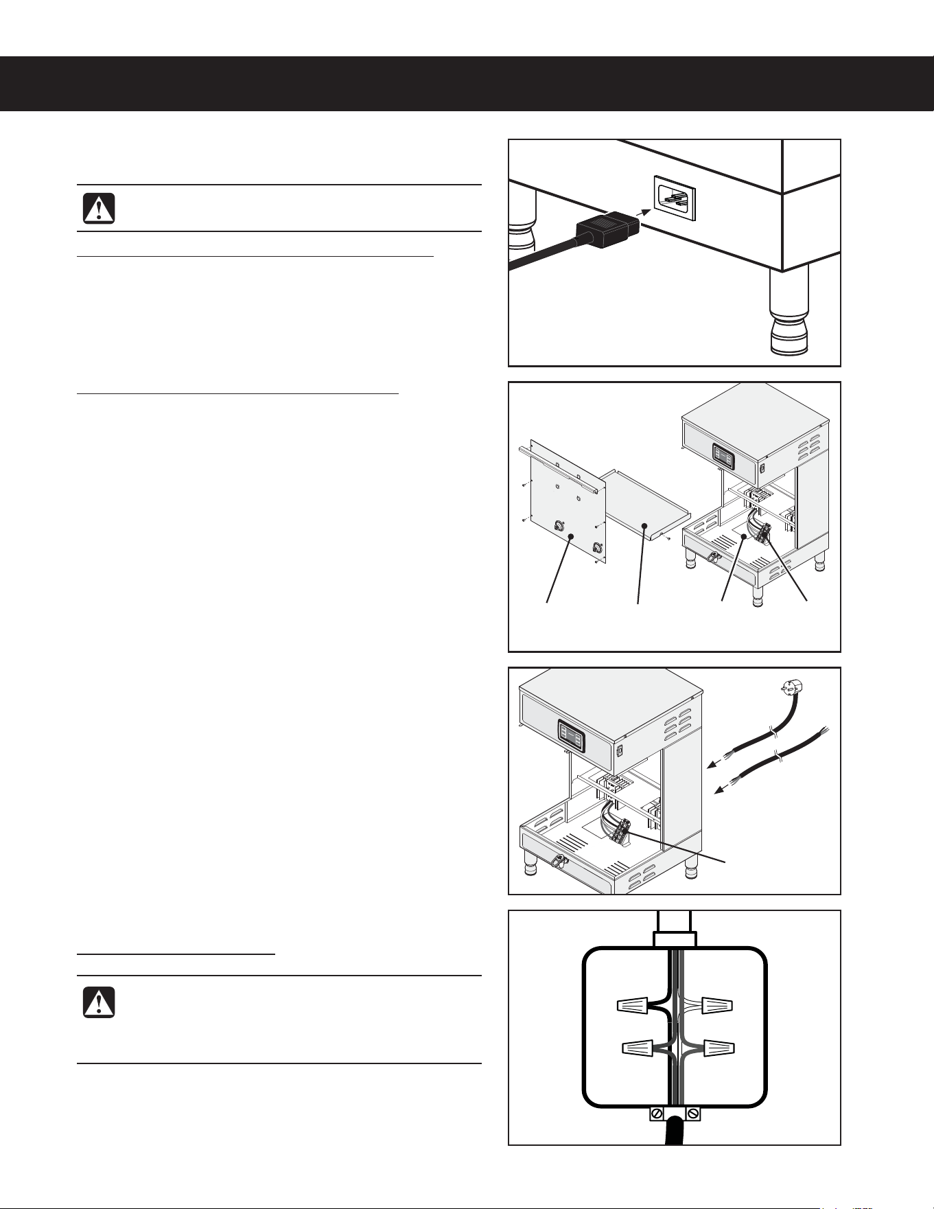
4 Remove the front cover.
5 Loosen the strain relief on the back of the brewer.
6 Disconnect the existing power cable from the terminal
block and remove.
INSTALLATION INSTRUCTIONS II14
Brew
deck
Front
panel
&RQ¿JXUDWLRQYDULHV
ZLWKPRGHO
:LULQJ
label
7HUPLQDO
block
&RQ¿JXUDWLRQYDULHV
ZLWKPRGHO
7HUPLQDO
block
Installation
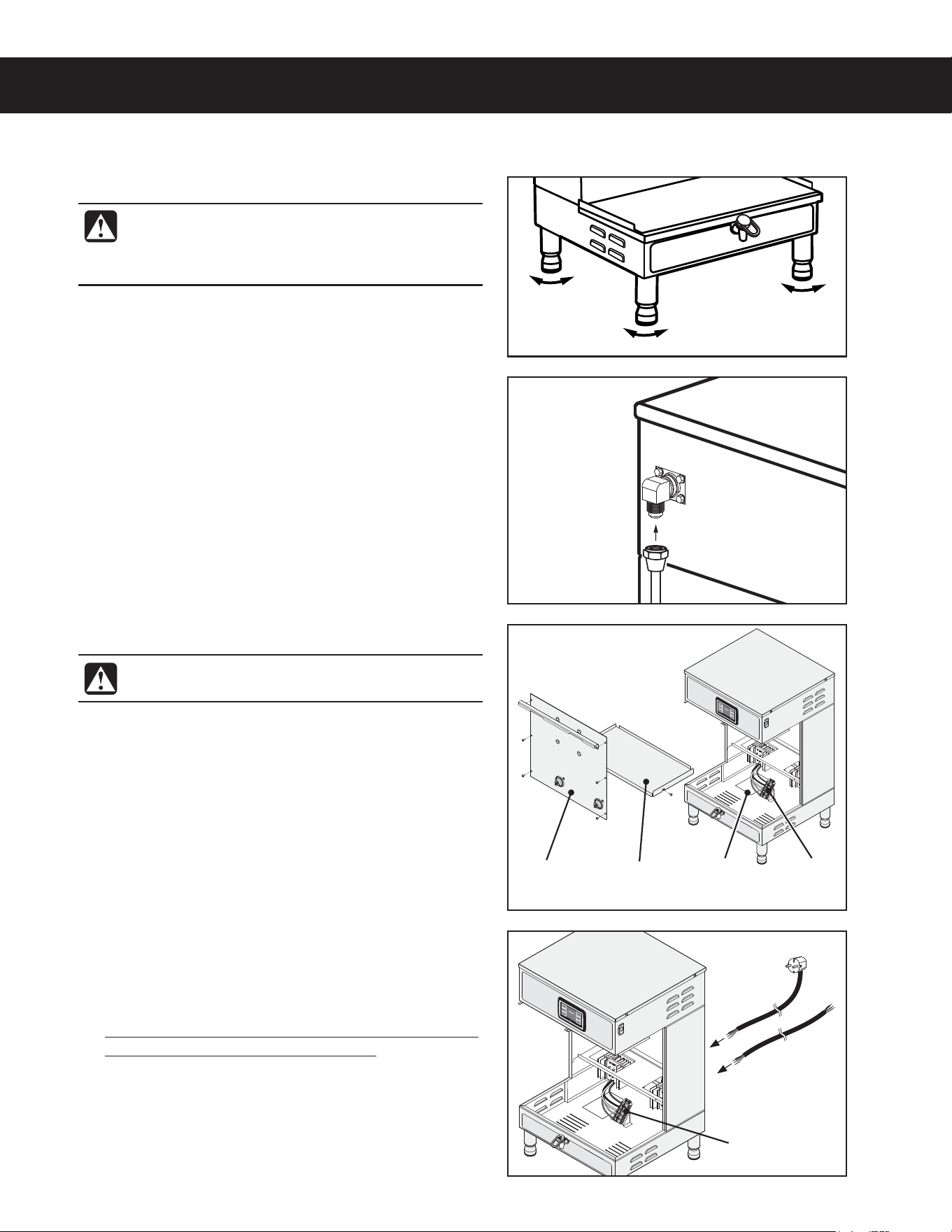
Leveling
1 Position the brewer on the counter top. Level it left to
right and front to back by turning the bottom of the
legs.
Connect the Water Supply
2 Flush the water supply line prior to installation to
QVSHFBJSBOEEFCSJTGSPNUIFXBUFSmMUFSBOEUVCJOH
3 $POOFDUUIFXBUFSTVQQMZMJOFUPUIFnBSFmUUJOHPO
the back of the brewer. Leave the water supply valve
closed until the power is connected.
WARNING: Use the leveling legs to level the
brewer only. Do not use them to adjust brewer
height. Do not extend them higher than
necessary.
((&.*/45"--"5*0/*/4536$5*0/4ø D
WARNING: Do not connect the power cord to
the power supply until instructed to do so.
or
'FFEUIF7PMUQPXFSDBCMFUISPVHIUIFTUSBJO
relief, into the brewer. The brewer may be wired for
connection directly to a junction box or for use with
a power plug that connects to an electrical outlet
meeting the brewer SPECIFICATIONS.
8 Disconnect and cap the jumper wire between the “C”
and “N” terminals on the terminal block.
9 Connect the wires on the power cable to the
terminal block inside the brewer according to the
ELECTRICAL SCHEMATIC.
Tighten the strain relief and replace the front cover.
Electrical Connection
Connection to a Junction Box
Connect the power cable wires to the terminals in
the junction box and replace the cover. See the
ELECTRICAL SCHEMATIC for the power supply
requirements.
INSTALLATION INSTRUCTIONS II14
Connecting the Brewer Wiring (Units That Come from
the Factory Without a Power Cord Attached)
Brewers With Power Connector Mounted to the Back
11 $POOFDUB$*&$QPXFSDPSEOPUTVQQMJFE
compatible with the electrical outlet installed in the
GBDJMJUZBOEUIBUNFFUTTQFDJmDBUJPOT
((&.*/45"--"5*0/*/4536$5*0/4ø D
WARNING: Do not connect the power cord to the
power supply until instructed to do so.
WARNING: Turn off power to the junction box at
the circuit breaker panel and lock out and tag the
circuit breaker before connecting the power cable
to the junction box.
Brewers With Strain Relief Mounted to the Back
12 Remove the front cover by removing the screws that
hold it in place.
13 Loosen the strain relief on the back of the brewer.
Brew
deck
Front
panel
&RQ¿JXUDWLRQYDULHV
ZLWKPRGHO
:LULQJ
label
7HUPLQDO
block
&RQ¿JXUDWLRQYDULHV
ZLWKPRGHO
7HUPLQDO
block
or
Power cable IURPEUHZHU
14 Feed the power cable into the brewer. The brewer may
be wired for connection directly to a junction box or for
use with a power plug that connects to an electrical
outlet meeting the brewer SPECIFICATIONS.
15 Connect the wires on the power cable to the terminal
CMPDLJOTJEFUIFCSFXFSBTTQFDJmFE4FFUIF
ELECTRICAL SCHEMATIC.
16 Tighten the strain relief and replace the front cover.
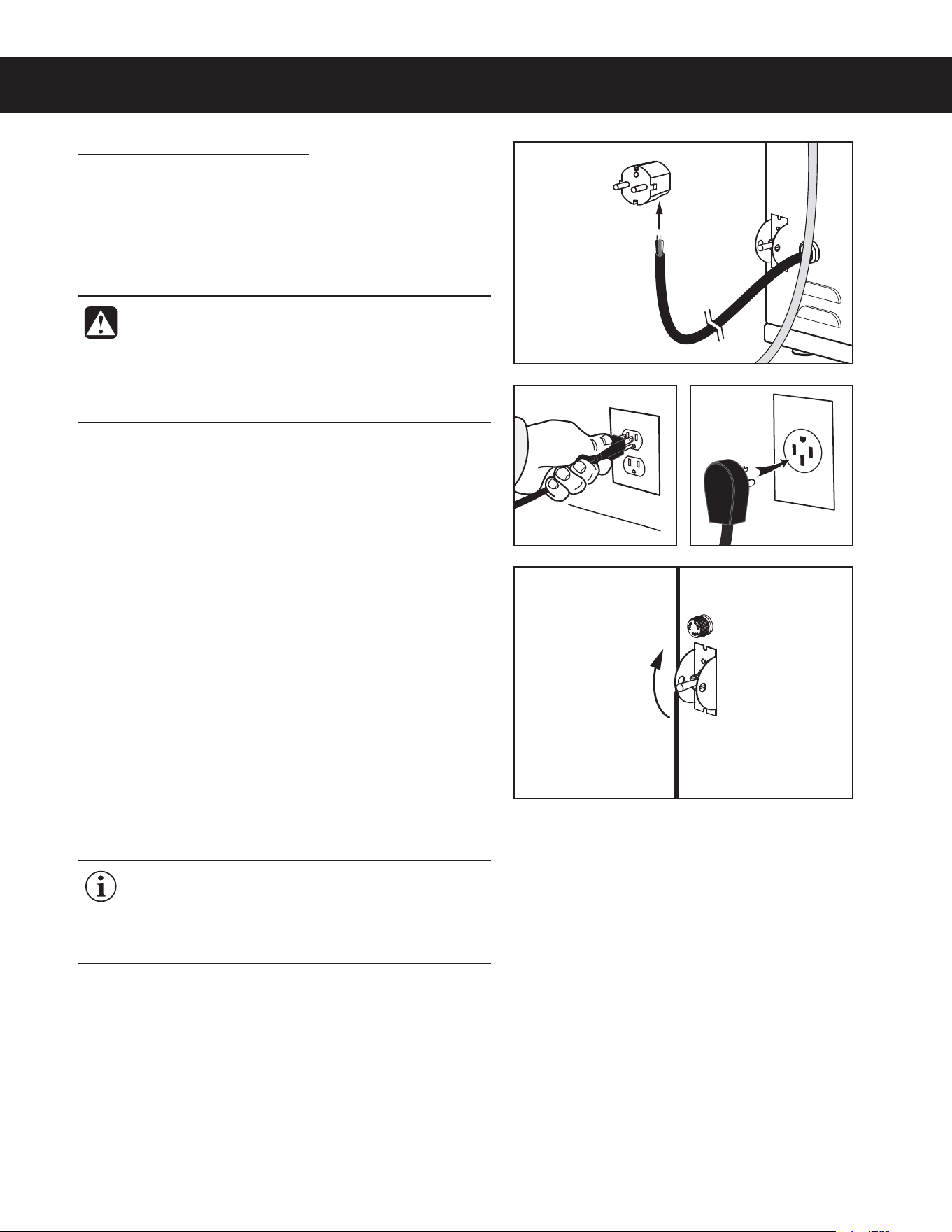
Connection to an Electrical Outlet
18 If not already installed, install the appropriate type of
power plug for your locality. Consult local electrical
codes to determine the approved type of power plug
for your region.
19 Connect the power plug to the electrical outlet.
Power Up the Brewer
Turn on the water supply valve.
21 Make sure that the circuit breaker supplying power to
the unit is on.
22 Turn the toggle switch on the back of the brewer to the
0/QPTJUJPO5IFXBUFSUBOLXJMMTUBSUUPmMM8IJMFUIF
UBOLJTmMMJOHJOTQFDUUIFXBUFSTVQQMZMJOFGPSMFBLT
23 Go to the PROGRAMMING GUIDE section and
program the brewer for the correct model and batch
number.
24 8IFOUIFXBUFSMFWFMJOUIFUBOLSJTFTUPUIFDPSSFDU
volume, the heating elements will turn on automatically.
Depending on the incoming water temperature and
UIFFMFDUSJDBMTQFDJmDBUJPOTUIFXBUFSUBOLUZQJDBMMZ
SFRVJSFTUPNJOVUFTUPSFBDIUIFGBDUPSZTFU
PQFSBUJOHUFNQFSBUVSF8IFOUIFXBUFSIBTIFBUFE
“Ready to Brew” should be on the display.
25 #FGPSFCSFXJOHGPSUIFmSTUUJNFEJTQFOTFP[
ml of hot water through the hot water faucet to help
purge air from the tubing inside the brewer.
26 #SFXBDZDMFPGBUMFBTUP[NMUPQVSHFBOZ
remaining air from the tubing. See OPERATING
INSTRUCTIONS. During the initial brew cycle and
XIFOFWFSUIFmMUFSJTSFQMBDFEZPVNBZIFBSUIF
TPVOETPGBJSCFJOHQVSHFEGSPNUIFmMUFSUVCJOHBOE
water tank.
INSTALLATION INSTRUCTIONS II14
((&.*/45"--"5*0/*/4536$5*0/4ø D
IMPORTANT: 8IFOPQFSBUJOHUIFCSFXFSBU
higher elevations, reduce the factory set operating
UFNQFSBUVSF¡'¡$CZ¡'¡$GPSFBDI
GUNPGFMFWBUJPOBCPWFGUN
See the PROGRAMMING GUIDE section.
Style
YDULHV
WARNING: Connect the power cord only to the
BQQSPQSJBUFUZQFBOETJ[FFMFDUSJDBMPVUMFU*GJUJT
not compatible, either have the cord replaced or
have the electrical outlet upgraded by a licensed
electrician. Do not use an extension cord. Do not
VTFBQPXFSDPSEQMVHUIBUJTEBNBHFE
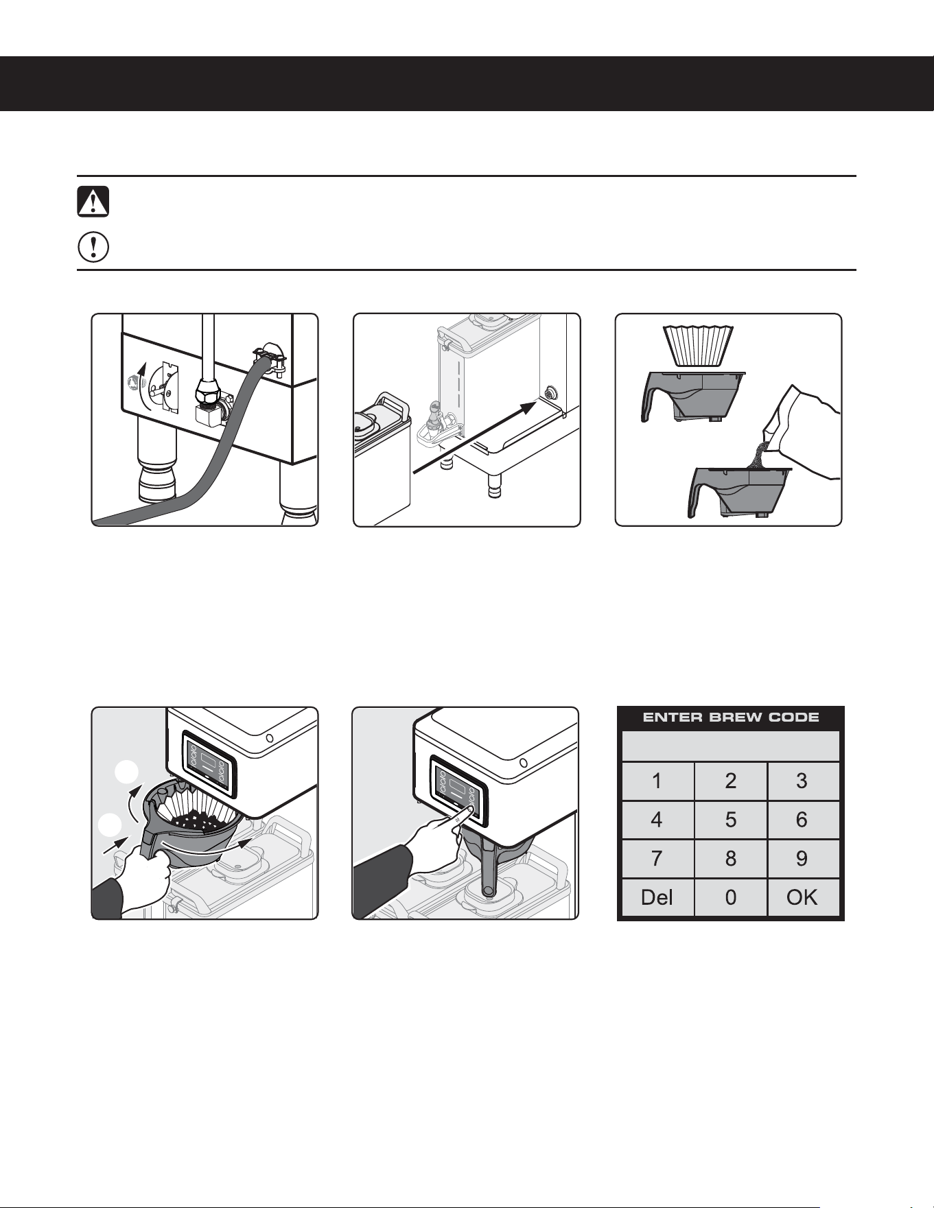
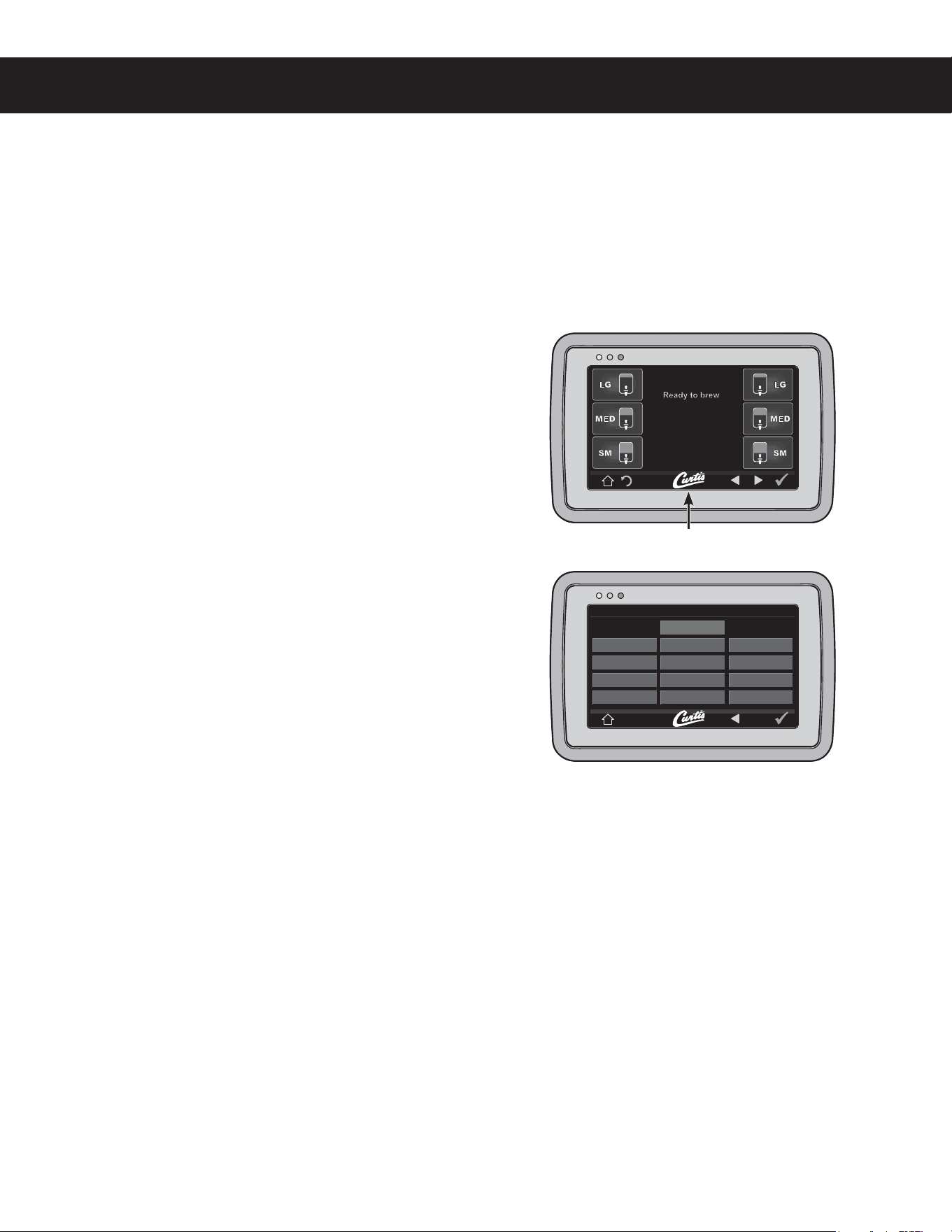
OPERATING INSTRUCTIONS OI65
Brewing Instructions
The G4 GEMX Intellifresh brewer is factory preset for optimal performance.
((&.9/01&3"5*/(*/4536$5*0/4ø NC
Place an empty dispenser on
the brew platform. Make sure
that the dispenser is pushed
all the way back against the
front cover and is making
contact with the electrical
socket.
3 *OTFSUBDMFBOQBQFSmMUFS
into the brew basket. Fill with
the proper amount of ground
coffee. Level the coffee in the
mMUFS
4 4MJEFUIFmMMFECSFXCBTLFU
into the brew rails under
the control panel. Slide it all
the way back until it stops.
Rotate the brew basket
UPEJSFDUUIFnPXJOUPUIF
desired dispenser.
)PMEZPVSmOHFSPOUIF
appropriate brew icon. As
soon as you hear the click
of the brew valve, lift your
mOHFS#SFXJOHXJMMCFHJO
The brewer will brew coffee based on the settings programmed into the universal control module (UCM). To
change the settings, see the PROGRAMMING GUIDE section.
The brewer should be ON.
$POmSNUIJTBUUIFSFBSUPHHMF
switch. “Ready to brew”
should be on the display.
WARNING - TO AVOID SCALDING, AVOID SPLASHING. Keep body parts clear of the brewer during
CSFXJOH%POPUSFNPWFUIFCSFXCBTLFUXIJMFi#SFXJOHwBQQFBSTPOUIFEJTQMBZ
NOTICE - Only use GEM3XN IntelliFresh
®
dispensers on GEMXN series IntelliFresh brewers.
6 If a keypad appears on
the display, the brew code
feature is enabled (default
is off). Brewing will start
immediately after you enter
the brew code. See the
PROGRAMMING GUIDE to
set up/disable the brew code.
c
d
INTELLIFRESH
®
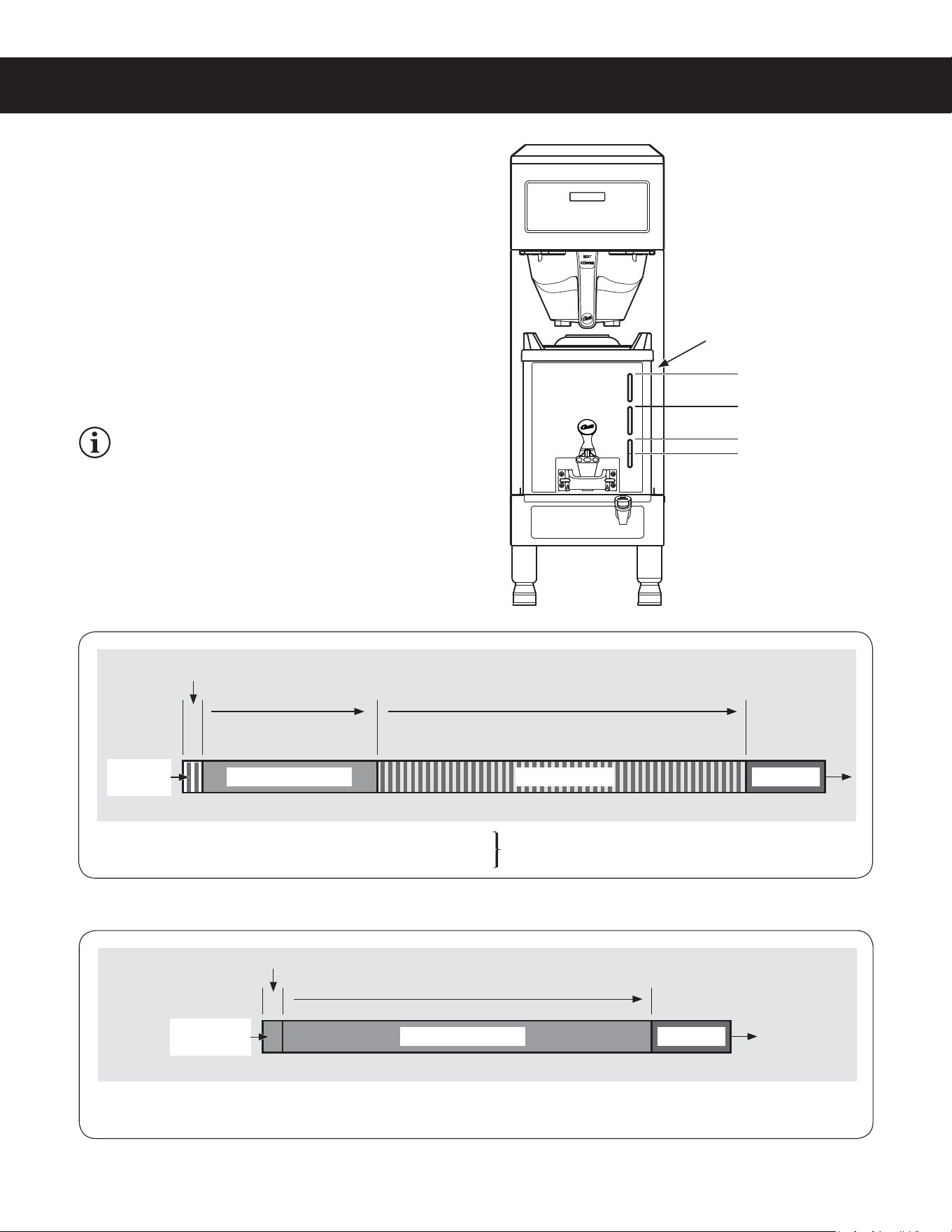
FEATURES IF2
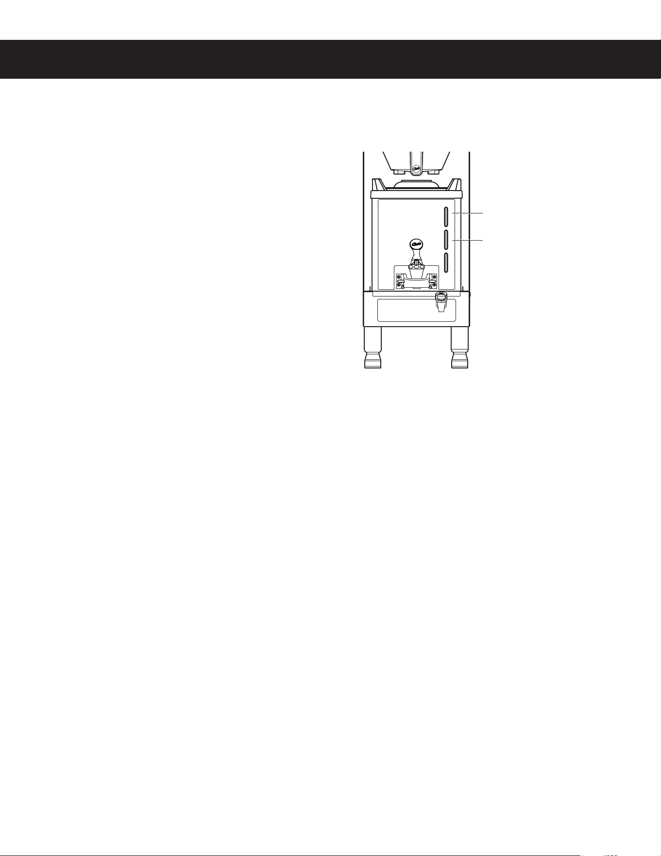
IntelliFresh Function and Features
The LED coffee level gauge on the front of the dispenser is
also the indicator for the IntelliFresh Quality Timer system.
When the quality timer is set to on (default), it alerts you to
when the coffee has exceeded the programmed freshness
time. The Quality Timer is activated via a signal sent
through corresponding connectors from the brewer to the
dispenser. When the warmer (automatically) shuts off, the
coffee level gauge turns blue, provided there is still coffee
in the dispenser. Otherwise the LEDs turn off completely.
See the PROGRAMMING GUIDE to change the Quality
Timer settings, including freshness (quality) time and LED
color.
GEM3XIFT SATELLITE, INTELLIFRESH FEATURES 060820A
/('VÁDVKDIWHUTXDOLW\WLPHUKDVH[SLUHG
DQGFRQWLQXHXQWLOZDUPHUVKXWVRII
4XDOLW\WLPHU/('VRQFRQVWDQW
6HWWLQJUDQJH0LQWR0LQ
%UHZF\FOH :DUPHU$XWR2II
+UVDIWHUTXDOLW\WLPHUKDVH[SLUHG
:DUPHU$XWR2II
+UVDIWHUEUHZF\FOHFRPSOHWHV
&RIIHH/HYHO*DXJH/('6WDWXV
&RIIHH/HYHO*DXJH/('6WDWXV
/('VÀDVKLQJ
2
LEDs blue
LEDs blue
LEDs
ÀDVKLQJ
1
/('VRQ
FRQVWDQW
1
1
&RORUFRႇHHLVIUHVK
2
&RORUFRႇHHLVQRORQJHUIUHVK
&RORUVDUHXVHUVHOHFWDEOH
see PROGRAMMING GUIDE
1
&RORU8VHUVHOHFWDEOHVHHPROGRAMMING GUIDE
LED Coffee Level Gauge - Intellifresh Quality Timer ON
LED Coffee Level Gauge - Quality Timer OFF
NOTE: After the brew cycle is complete, if the
GEMX dispenser is transferred from the brewer to
a Curtis IntelliFresh warmer stand, the following
dispenser settings will remain the same: Quality
Timer, Warmer Default (heat setting) and dispenser
(Intellifresh) Color Scheme.
/('VRQFRQVWDQW
1
/('VRQFRQVWDQW
1
/('&RႇHHOHYHOJDXJH
4XDOLW\7LPHU
1ò*DOORQV
1 *DOORQ
ò*DOORQ
¼*DOORQ
%UHZHUVW\OHYDULHV
ZLWKPRGHOQXPEHU
9ROXPHVDUHDSSUR[LPDWH
%UHZF\FOH

NOTICE - Do not use cleaning liquids, compounds or powders containing chlorine (bleach) or corrosives.
5IFTFQSPEVDUTQSPNPUFDPSSPTJPOBOEXJMMEBNBHFUIFmOJTIFT USE OF THESE PRODUCTS WILL VOID
THE WARRANTY.
CLEANING INSTRUCTIONS CI1
Cleaning The Brewer - Daily
BREWERS - GENERIC, CLEANING INSTRUCTIONS 080416B
WARNING: HOT SURFACES - To avoid injury, allow the brewer and dispenser(s) to cool before cleaning.
The brewer should be OFF.5VSOUIFCSFXFSPGGCZnJQQJOHUIFSFBSUPHHMFTXJUDIUPUIF0''QPTJUJPO
1 Remove the dispenser(s). Wipe exterior brewer surfaces with a damp cloth to remove spills and debris.
2 Remove the brew basket(s) and clean them in a mild detergent solution. Use a soft bristled brush for hard to
clean areas. Rinse with clean water, then dry.
3 Wipe the spray head area with a cloth soaked in a mild detergent solution. Rinse with a cloth soaked with
clean water removing any residual detergent. Use a clean, soft cloth to dry.
4 Dump out the drip tray(s) (if applicable). Rinse with clean water, then dry with a soft, clean cloth.
Cleaning The Brewer - Weekly
The brewer should be OFF.5VSOUIFCSFXFSPGGCZnJQQJOHUIFSFBSUPHHMFTXJUDIUPUIF0''QPTJUJPO
1 Remove the spray head(s), unscrewing counterclockwise from the dome plate.
2 Thoroughly clean and rinse the dome plate area.
3 Clean the brew basket rails with a brush soaked with a mild detergent solution. Rinse the area with a cloth
soaked with clean water, removing any residual detergent.
4 Dry the area with a soft, clean cloth.
5 Reattach the spray head(s).
WARNING: DO NOT immerse the brewer in water or any other liquid.
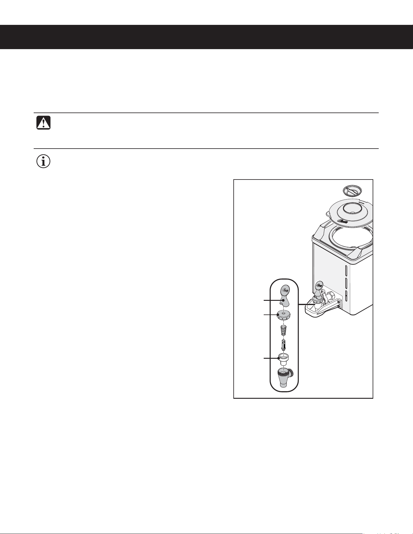
Cleaning the Liner
1 Remove the dispenser from the brewer and remove the
lid. Set the lid aside. Rinse out the liner.
2 Wash - Prepare a mild solution of detergent and warm
water. Wipe the exterior surfaces of the dispenser with
a sponge moistened with the detergent solution to
remove spills and debris. Fill the liner with the detergent
solution. Take a soft nylon brush and scrub out the
stainless steel liner.
3 Rinse - Rinse out the liner with clean, warm water.
4 Sanitize - Drop one TABZ Z95 tablet into the liner. Fill
to the top with hot water (122°F/50°C min.). Stir the
contents. Allow the liner to soak for 5 to 10 minutes.
5 Open the faucet and drain out the dispenser (to clean
the faucet shank).
6 Fill the liner to the top with clean, warm water and drain
through the faucet (to rinse the faucet shank).
7 Fill the liner to the top with water a second time and
drain through the faucet.
8 Disassemble the faucet - Unscrew the handle/bonnet
assembly from the top of the faucet and remove it.
Inspect the seat cup for wear. Replace the seat cup if it
is damaged.
9 Air Dry - Turn the dispenser upside down and allow to
air dry.
continued...
Cleaning the Dispenser (Daily)
CLEANING INSTRUCTIONS CI29
GEMX
™
SATELLITE, CLEANING INSTRUCTIONS 051420C
IMPORTANT: Clean the dispenser daily to avoid the build up of coffee oil residue on the Intellifresh
®
sensors inside the liner. Residue build up may cause the Intellifresh indicator to malfunction.
Seat cup
Handle
Bonnet
WARNING: DO NOT immerse the dispenser in water or any other liquid. Do not place the dispenser in a
dishwasher. Doing so will void the warranty. Do not use harsh powders or cleansers containing chlorine.
Do not use a wire brush or scouring pad to clean inside the liner. To avoid damage, DO NOT use a
brush to clean the faucet or the inside of the faucet shank (outlet).
The following cleaners are required to properly maintain the dispenser:
• Mild solution of dish-washing detergent and warm water
• TABZ
™
Z95 Coffee Equipment Cleaner Tablets (Curtis PN WC-79000)
• One-Pro Beverage Equipment Cleaner
Style may vary
CLEANING INSTRUCTIONS CI29
GEMX
™
SATELLITE, CLEANING INSTRUCTIONS 051420C
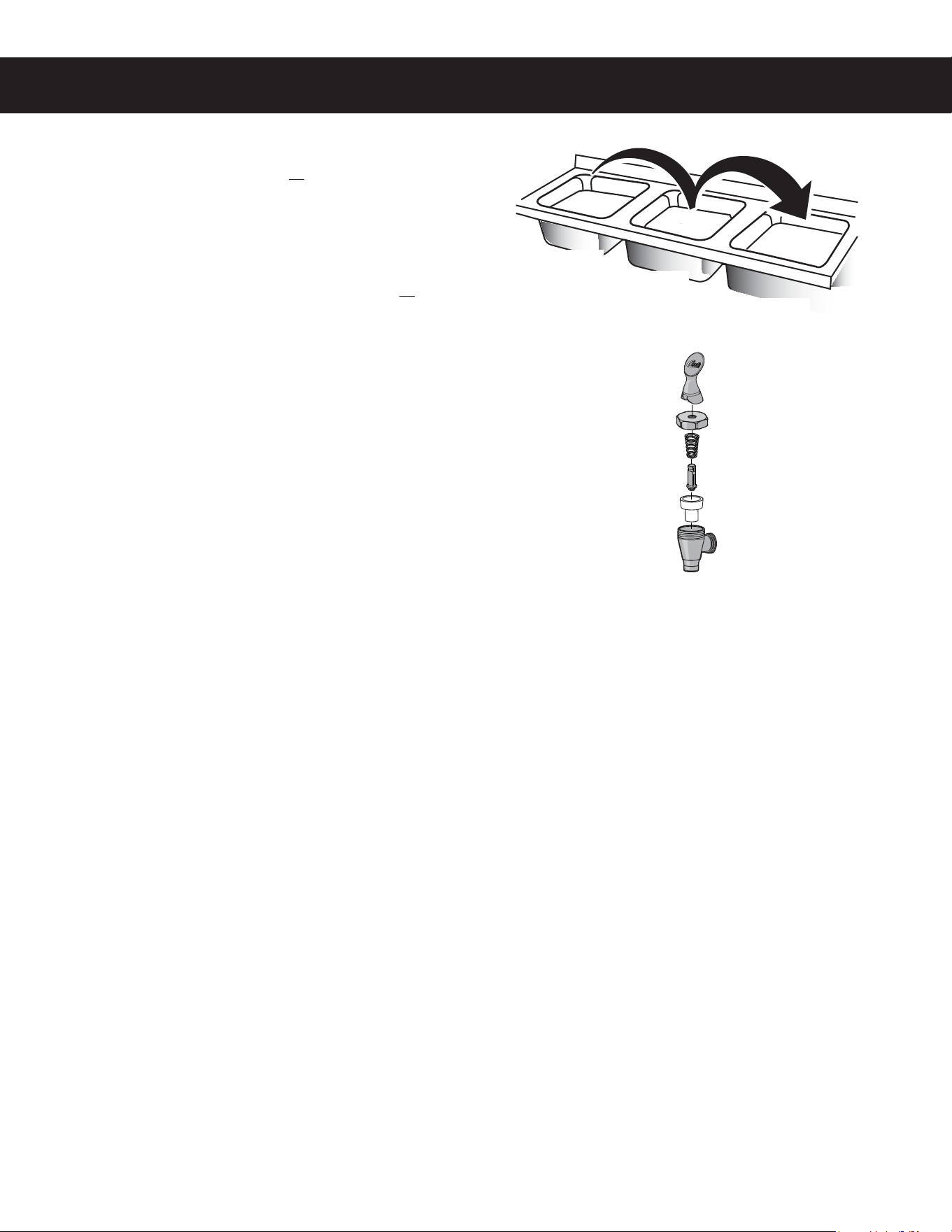
Cleaning the Faucet Parts
10 Wash - Wash the lid and all faucet parts with the
detergent solution.
11 Rinse - Thoroughly rinse all parts with clean, warm
water.
12 Sanitize - After rinsing, place the lid and all faucet
parts in a sink to be sanitized. Immerse them in One-Pro
cleaner mixed at a ratio of 1 oz. (28 g.) per 5 gal. (19 L)
of hot water (122°F/50°C min.). Allow the parts to soak
for 15 minutes.
13 Air Dry - Allow all parts to thoroughly air dry.
14 Reassemble - When dry, reassemble the handle/
bonnet. Hand tighten the handle/bonnet onto the top of
the faucet assembly. Reinstall the lid.
WASH
RINSE
SANITIZE
PROGRAMMING GUIDE PG1
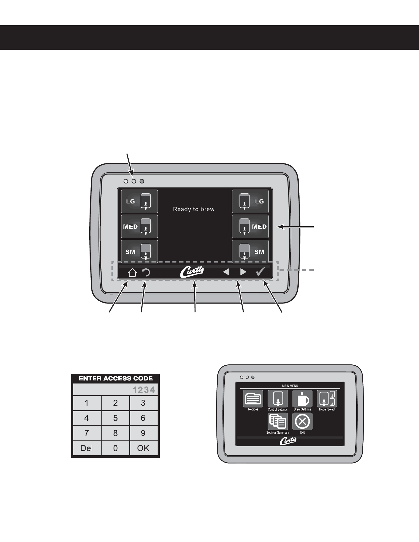
2 The ACCESS CODE screen will appear. The
default pass code is 1 2 3 4. Once the code is
entered, press OK. The MAIN MENU screen will
appear. The access code can be reset in the
Control Settings sub-menu, under Passwords.
Manual Programming Mode
1 5BQUIFXIJUF$VSUJTMPHPPOUIFUPVDITDSFFOmWFUJNFTUPFOUFSQSPHSBNNJOHNPEF
3 The MAIN MENU screen contains a series of sub-
NFOVJDPOT5IFJDPOTWBSZCBTFEPOUIFNPEFM
selected under the Model Select sub-menu. For
UIFCSFXFSUPPQFSBUFQSPQFSMZUIFNPEFMTFMFDUFE
must match the model series on the brewer model
OVNCFSMBCFMBGmYFEUPUIFPVUTJEFPGUIFNBDIJOF
(130(3"..*/((6*%&ø H
Status lights
Brew Buttons
Curtis logoHome Undo Scroll
left/right
Return to
previous
Control symbols - all
symbols may not be
present at the same
time
Display view varies
with model
Touchscreen Control Module Overview
5IFUPVDITDSFFOUVSOTPOXIFOFWFSUIFSFBSUPHHMFTXJUDIJTPO5IFTZNCPMCVUUPOTPOUIFTDSFFODPOUSPM
PQFSBUJPOBOEQSPHSBNNJOH1SFTTJOHUIFPOTDSFFOTZNCPMTBOECVUUPOTXJUIZPVSmOHFSUJQBDUJWBUFTUIFWBSJPVT
functions. The default screen, as well as additional control buttons are shown below.
There are two methods for changing the default settings on G4 brewers. The settings can be programmed
NBOVBMMZVTJOHUIFCSFXFSUPVDITDSFFOTFFCFMPXPSBVUPNBUJDBMMZVTJOHUIF64#6OJWFSTBM4FSJBM#VTEBUB
port on the side of the brewer (see Automatic Programming - USB).
PROGRAMMING GUIDE PG1
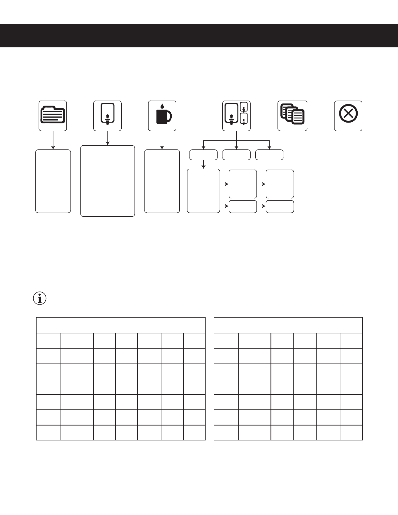
Manual Programming Mode (cont.)
4IPXOCFMPXBOEPOUIFGPMMPXJOHQBHFTBSFUIFTVCNFOVTBWBJMBCMFGPSUIFQSPHSBNNJOH."*/.&/65IF
JDPOTBOEQSPHSBNNJOHPQUJPOTUIBUBQQFBSWBSZCBTFEPOUIFCSFXFSNPEFMTFMFDUFEVOEFS.PEFM4FMFDU
Recipes Menu
4FMFDUGSPNUIFGPMMPXJOHDPGGFFUZQFT(PVSNFU45%TUBOEBSE-JHIU3PBTU%BSL3PBTU)JHI:JFME'JMUFS
1BDL%FDBGPS$VTUPN3FDJQFT5IFGBDUPSZEFGBVMUTFUUJOHJT(PVSNFU45%4FMFDUJOHUIFDPGGFFUZQFTFUT
UIFUFNQFSBUVSFBOEWBSJPVTCSFXTFUUJOHTGPSUIFCSFXFSTIPXOJOUIFBrew SettingsTFDUJPOUPUIFGBDUPSZ
SFDPNNFOEFETFUUJOHTGPSUIFUZQFPGDPGGFFCFJOHCSFXFE*GEFTJSFEUIFJOEJWJEVBMCSFXTFUUJOHTNBZCF
DIBOHFEPODFUIFDPGGFFUZQFJTTFMFDUFEUPNFFUZPVSCSFXJOHOFFET
IMPORTANT:*GZPVDIBOHFBOZPGUIFCSFXFSTFUUJOHTPOUIFGPMMPXJOHQBHFTTPNFPSBMMPGUIFNNBZCF
NPEJmFEJGZPVDIBOHFUIFDPGGFFUZQFBGUFSXBSEVTJOHUIF3FDJQFTNFOV
continued...
(130(3"..*/((6*%&ø H
Tea
Gourmet Std
Light Roast
Dark Roast
High Yield
Filter Pack
Decaf
Custom Recipe
Model Select
Control Settings Brew Settings
Recipes
ComboCoffee
Settings Summary
Exit
Temperature Settings
Warmer Settings
Quality Timer
Energy Savings
Satellite LED Color
Sounds
Diagnostics
Display Settings
Preventative Maintenance
Brew Counter
Passwords
Master Reset
Regional Settings
Rinse Volume
By Volume/Time
Pre/Pulse
Bypass
Drip Out
Gemini
Gemini IF
GEMX
GEMX Narrow
TP
TPX
TP1
TPX1G
Single
Twin
Single
Twin
*
*Only models covered by this user guide are shown.
One Batch
Two Batch
One Batch
Two Batch
Three Batch
Recipe Default Brew Settings
(all models except G4TP1 and G4TPX1 series)
Temperature
Pulse
Brew
Bypass
Large
Bypass
Medium
Bypass
Small
Pre-
Infusion
Gourmet
STD
200°F/92°C C 35% 10% 0% OFF
Light
Roast
200°F/92°C C 45% 15% 0% OFF
Dark
Roast
196°F/91°C OFF 25% 5% 0% 60/60
High
Yield
192°F/89°C OFF 35% 10% 0% 60/60
Filter
Pack
200°F/92°C C 0% 0% 0% OFF
Decaf 200°F/92°C C 0% 0% 0% OFF
Recipe Default Brew Settings
(G4TP1 and G4TPX1 series)
Temperature
Pulse
Brew
Bypass
Large
Bypass
Small
Pre-
Infusion
Gourmet
STD
200°F/92°C C 10% 0% OFF
Light
Roast
200°F/92°C C 15% 0% OFF
Dark
Roast
196°F/91°C OFF 5% 0% 60/60
High
Yield
192°F/89°C OFF 10% 0% 60/60
Filter
Pack
200°F/92°C C 0% 0% OFF
Decaf 200°F/92°C C 0% 0% OFF

PROGRAMMING GUIDE PG1
(130(3"..*/((6*%&ø H
Control Settings Menu
Temperature - TFUTUIFCSFXJOHUFNQFSBUVSFPGUIFXBUFSIFMEJOUIFXBUFSUBOL5IFGBDUPSZEFGBVMUTFUUJOHJT
'¡$5IFTFUUJOHSBOHFJT'UP'¡$UP¡$
Warmer Settings (some models)
• Auto-Off (G4GEMS/G4GEMT series) - adjusts the time that elapses before the dispenser warmer
TIVUTPGGBVUPNBUJDBMMZ5IFGBDUPSZEFGBVMUTFUUJOHJT%JTBCMFE5IFTFUUJOHSBOHFJTUPIPVST
• Auto-Off (G4GEMSIF/G4GEMTIF series) - adjusts the time that elapses before the dispenser
XBSNFSTIVUTPGGBVUPNBUJDBMMZ5IFGBDUPSZEFGBVMUTFUUJOHJTIPVST
• Power Setting (All G4 Gemini series) - TFUTUIFXBSNFSQPXFSMFWFM5IFGBDUPSZEFGBVMUTFUUJOHJT
.&%5IFBWBJMBCMFTFUUJOHTBSF)*().&%PS-08
Quality Timer (G4GEMSIF/G4GEMTIF and G4GEMX series only) - adjusts the Intellifresh
®
RVBMJUZUJNFS
5IFGBDUPSZEFGBVMUTFUUJOHJTIPVST*UOPUJmFTUIFVTFSUIBUUIFDPGGFFJTOPMPOHFSGSFTI5IFTFUUJOHSBOHFJT
NJOVUFTUPIPVSTGPS((&.4*'((&.5*'TFSJFTBOENJOVUFTUPIPVSTNJOVUFTGPS((&.9
series.
Energy Save Mode - TBWFTFOFSHZEVSJOHQFSJPETPGOPOVTF5IFGBDUPSZEFGBVMUTFUUJOHJT/P$IBOHF
FOFSHZTBWFSPGG5IFTFUUJOHPQUJPOTBSF/P$IBOHFUVSOPGGUIFIFBUJOHFMFNFOUBGUFSGPVSIPVSTPGOPOVTF
PSSFEVDFUIFIFBUJOHFMFNFOUUFNQFSBUVSFUP¡'¡$BGUFSGPVSIPVSTPGOPOVTF
Satellite Color (G4GEMX series models only) - changes the color scheme of the dispenser. The default
TFUUJOHDPMPSJTXIJUFXIFOUIFRVBMJUZUJNFSJTPOSFEXIFOJUJTPGG
Sounds - UVSOTUIFCFFQFSIFBSEFBDIUJNFBCVUUPOJTQSFTTFEPOPSPGG5IFGBDUPSZEFGBVMUTFUUJOHJT0O
Diagnostics - SVOTUIFTZTUFNBVUPUFTU4FFUIFTroubleshooting Guide for more details.
Display Settings
• Brew Timer - UVSOTUIFCSFXUJNFSPOUIFEJTQMBZPOBOEPGG5IFGBDUPSZEFGBVMUTFUUJOHJT4IPX
• Quality Timer (G4GEMSIF/G4GEMTIF and G4GEMX series only) -5VSOTUIFRVBMJUZUJNFSEJTQMBZ
POBOEPGG5IFGBDUPSZEFGBVMUTFUUJOHJT4IPX
• Rinse Server Message -UVSOTUIFi3JOTF4FSWFSCFGPSF#SFXJOHwNFTTBHFEJTQMBZPOBOEPGG5IF
GBDUPSZEFGBVMUTFUUJOHJT4IPX
• Warmer Icon (G4GEMSIF/G4GEMTIF and G4GEMX series only) - turns the warmer icon on and off.
*UBQQFBSTPOUIFEJTQMBZXIFOUIFXBSNFSJTPO5IFGBDUPSZEFGBVMUTFUUJOHJT4IPX
• Screen saver -UVSOTUIFEJTQMBZTDSFFOTBWFSPOBOEPGG5IFGBDUPSZEFGBVMUTFUUJOHJT0GG
• Display Name -DIBOHFTUIFDPNQBOZOBNFPOUIFEJTQMBZ5IFGBDUPSZEFGBVMUJTCMBOL
• Brew button icon -TXJUDIFTUIFCSFXCVUUPOJDPOTUIBUBQQFBSPOUIFEJTQMBZ0SJHJOBMPSCBHTUIF
GBDUPSZEFGBVMUTFUUJOHJT0SJHJOBM
Preventive Maintenance
• Maintenance Interval -UVSOTPOPGGBOEBEKVTUTUIFQSFWFOUJWFNBJOUFOBODFCSFXNPOJUPS5IF
GBDUPSZEFGBVMUTFUUJOHJT%JTBCMFE8IFO&OBCMFEJUNFBTVSFTUIFOVNCFSPGHBMMPOTCSFXFECFGPSF
UIFNBJOUFOBODFSFNJOEFSBQQFBSTPOUIFEJTQMBZ5IFTFUUJOHSBOHFJTUPHBM-
• Service Telephone Number -TFUTUIFTFSWJDFQIPOFOVNCFSUIBUBQQFBSTPOUIFEJTQMBZXIFOUIF
6$.EFUFDUTBOFSSPSDPOEJUJPO5IFGBDUPSZEFGBVMUJT
Brew Counter -8IFOBDDFTTFEUIJTGFBUVSFEJTQMBZTUIFUPUBMOVNCFSPGCSFXDZDMFTBOEUIFSFTFUUBCMF
CSFXDZDMFDPVOUFSOVNCFSPGCSFXDZDMFTTJODFMBTUSFTFU
continued...

PROGRAMMING GUIDE PG1
(130(3"..*/((6*%&ø H
Control Settings Menu (cont.)
Passwords
• Programming Password -DIBOHFTUIFQSPHSBNNJOHNFOVQBTTXPSE"MXBZTBDUJWF5IFGBDUPSZ
default is 1234.
• Brew Password - turns the brew access password feature on and off and is used to create the
CSFXQBTTXPSE5IJTGFBUVSFQSFWFOUTCSFXJOHCZVOBVUIPSJ[FEQFSTPOT5IFGBDUPSZEFGBVMUTFUUJOH
JT%JTBCMFE8IFO&OBCMFEBOBDDFTTDPEFLFZQBEBQQFBSTPOUIFTDSFFOXIFOUIFCSFXCVUUPOJT
pressed. The correct access code must be entered before brewing will proceed.
• USB Password - UVSOTUIF64#TDSFFOBDDFTTQBTTXPSEPOBOEPGGBOEJTVTFEUPDSFBUFUIF64#
BDDFTTQBTTXPSE5IJTGFBUVSFQSFWFOUTBDDFTTCZVOBVUIPSJ[FEQFSTPOTUPUIF64#QSPHSBNNJOH
TDSFFOT5IFGBDUPSZEFGBVMUTFUUJOHJT%JTBCMFE8IFO&OBCMFEBOBDDFTTDPEFLFZQBEBQQFBSTPO
UIFTDSFFOXIFOUIFVTFSBUUFNQUTUPBDDFTTUIF64#NFOVT
Master Reset - SFTFUTUIFCSFXFSVOJWFSTBMDPOUSPMNPEVMF6$.UPUIFGBDUPSZEFGBVMUTFUUJOHT
Regional Settings
• SI/US -TXJUDIFTUIFCSFXFSVOJUTFUUJOHTCFUXFFO64BOENFUSJD5IFGBDUPSZEFGBVMUTFUUJOHJT64
• Language -DIBOHFTUIFMBOHVBHFUIBUBQQFBSTPOUIFEJTQMBZ5IFGBDUPSZEFGBVMUTFUUJOHJT&OHMJTI
Rinse Volume - UVSOTUIFEJTQFOTFSSJOTFPQUJPOTPOBOEPGG5IFGBDUPSZEFGBVMUTFUUJOHJT%JTBCMFE5IF
TFUUJOHSBOHFGPSSJOTFWPMVNFJTP[UPP[
Brew Settings Menu
8IFOZPVmSTUFOUFSUIF#SFX4FUUJOHTQSPHSBNNJOHNFOVZPVXJMMCFBTLFEUPTFMFDUQSFTTB#3&8CVUUPOUP
DIBOHFUIFTFUUJOHTGPS5PQSPHSBNNPSFUIBOPOF#3&8CVUUPOmOJTIQSPHSBNNJOHUIFmSTUUIFOreenter the
Brew Settings menu to program the second.
Brew by Volume (G4TP1 and G4TPX1 series) - BEKVTUTUIFWPMVNFCSFXFE5IFGBDUPSZEFGBVMUTFUUJOHT
(PVSNFU45%TFUUJOHBSF-"3(&P[P[-NM
and
4."--P[P[-NM8JUI
BEJTQFOTFSJOQMBDFQSFTT45"35UPCFHJO8IFOUIFEFTJSFEWPMVNFJTSFBDIFEQSFTT45015IFCSFX
WPMVNFJTOPXTFU
Brew by Volume (all models except G4TP1 and G4TPX1 series) - BEKVTUTUIFWPMVNFCSFXFE5IFGBDUPSZ
EFGBVMUTFUUJOHT(PVSNFU45%TFUUJOHBSF-"3(&P[P[-NM
.&%*6.P[P[
-NM
4."--P[P[-NM8JUIBEJTQFOTFSJOQMBDFQSFTT45"35UPCFHJO8IFOUIF
EFTJSFEWPMVNFJTSFBDIFEQSFTT45015IFCSFXWPMVNFJTOPXTFU
Brew by Time (G4TP1 and G4TPX1 series) - BEKVTUTUIFBNPVOUPGDPGGFFCSFXFECZUJNFSBUIFSUIBOCZ
WPMVNF5IFGBDUPSZEFGBVMUTFUUJOHT<(PVSNFU45%TFUUJOH>BSF-"3(&NJOTFDBOE4."--NJO
sec.
Brew by Time (all models except G4TP1 and G4TPX1 series) - BEKVTUTUIFBNPVOUPGDPGGFFCSFXFECZ
UJNFSBUIFSUIBOCZWPMVNF5IFGBDUPSZEFGBVMUTFUUJOHT<(PVSNFU45%TFUUJOH>BSF-"3(&NJOTFD
.&%*6.NJOTFDBOE4."--NJOTFD
Pre-Infusion - TFUTUIFCSFXFSQSFJOGVTJPOUJNF1VMTF#SFXNVTUCF0GGUPBDDFTTUIFGBDUPSZEFGBVMU
TFUUJOH<(PVSNFU45%TFUUJOH>JT0GG1SF*OGVTJPOJODSFBTFTDPOUSPMPGDPGGFFDMBSJUZBOEFYUSBDUJPO8IFO
UVSOFE0OUIFTFUUJOHSBOHFJTUPTFDPOET
continued...

PROGRAMMING GUIDE PG1
(130(3"..*/((6*%&ø H
Brew Settings Menu (cont.)
Pulse Brew - TFMFDUTUIFQVMTFCSFXQBUUFSO1SF*OGVTJPONVTUCFPGGUPBDDFTTUIFGBDUPSZEFGBVMUTFUUJOH
<(PVSNFU45%TFUUJOH>JT$5IFQVMTFCSFXQBUUFSOTFMFDUFEiUVOFTwPSDIBOHFTUIFnBWPSPGUIFDPGGFF*G
FOFSHZTBWFSNPEFJTPOBGUFSQSFTTJOHUIFCSFXCVUUPOUIFCSFXDZDMFXJMMTUBSUXIFOUIFXBUFSJOUIFUBOL
reaches brewing temperature.
Pulse Brew Guidelines
• 'JMUFSQBDLUZQFDPGGFFTUZQJDBMMZFYUSBDUCFUUFSXJUIUIF"BOE#QVMTFTFUUJOH
• %FDBGGFJOBUFEDPGGFFTUZQJDBMMZFYUSBDUCFUUFSXJUIUIF#QVMTFTFUUJOH
• )JHIZJFMEDPGGFFTUZQJDBMMZFYUSBDUCFUUFSXJUIUIF$QVMTFTFUUJOH0GDPVSTFBOZPGUIF"#PS$
TFUUJOHTNBZCFVTFEUPTVJUZPVSUBTUFQSPmMF
• Settings D and E are manual pulse counts.
By-Pass (G4TP1 and G4TPX1 series) - IFMQTDPOUSPMFYUSBDUJPOGPSMBSHFSCSFXT5IFGBDUPSZEFGBVMU
TFUUJOHT<(PVSNFU45%>BSF-"3(&BOE4."--#ZQBTTSFEVDFTDPOUBDUUJNFUPBWPJEFYUSBDUJPOPG
VOEFTJSBCMFCJUUFSBOEIBSTInBWPSDPNQPVOET5IFTFUUJOHSBOHFJTUP
By-Pass (all models except G4TP1 and G4TPX1 series) - IFMQTDPOUSPMFYUSBDUJPOGPSMBSHFSCSFXT5IF
GBDUPSZEFGBVMUTFUUJOHT<(PVSNFU45%>BSF-"3(&.&%*6.BOE4."--#ZQBTTSFEVDFT
DPOUBDUUJNFUPBWPJEFYUSBDUJPOPGCJUUFSBOEIBSTInBWPSDPNQPVOET5IFTFUUJOHSBOHFJTUP
Drip-out Mode - TFUTUIFESJQPVUNPEFUJNFS"GUFSXBUFSTUPQTnPXJOHJUBMMPXTBEEJUJPOBMUJNFGPSUIFXBUFS
UPESBJOGSPNUIFCSFXCBTLFUCFGPSFi#SFXJOHwEJTBQQFBSTGSPNUIFEJTQMBZ5IFGBDUPSZEFGBVMUTFUUJOHJTUXP
NJOVUFT5IJTGFBUVSFSFEVDFTUIFDIBODFUIBUUIFCSFXCBTLFUXJMMCFSFNPWFEUPPFBSMZ5IFTFUUJOHSBOHFJT
TFDPOETUPNJOVUFT
Model Select Menu
Batch Size - 5IFNPEFMOVNCFSBOETJOHMFUXJOTFUUJOHTBSFTFUBUUIFGBDUPSZBOETIPVMESFNBJOTFUUPNBUDI
UIFNPEFMOVNCFSMBCFMBGmYFEUPUIFVOJU)PXFWFSUIJTTVCNFOVDBOCFVTFECZUIFFOEVTFSUPTFMFDUUIF
OVNCFSPGCSFXCVUUPOTCBUDITJ[FUIBUBQQFBSPOUIFEJTQMBZ6QPOFOUFSJOHUIF.PEFM4FMFDUNFOVTFMFDU
UIFDPSSFDUNPEFMOVNCFSBOETJOHMFUXJOTFUUJOHUIFOTFMFDUUIFCBUDITJ[F
Setting Description
A Toward the beginning of brew cycle: 4 cycles of 10 seconds on and 10 seconds off, then on until end of brew cycle.
B
Starts towards ends of brew cycle. 4 cycles of 10 seconds off and 4 cycles of 10 seconds on. Ends when brew
cycle ends.
C Starts at beginning of brew cycle. 5 cycles of 25 seconds on and 20 seconds off, then on until end of brew cycle.
D
Manually set. Starts at beginning of brew cycle. Number of pulses is adjustable from 1 to 12. Pulse on time and off
time are both adjustable from 5 to 150 seconds.
E
Manually set. Starts at beginning of brew cycle. Number of pulses is adjustable from 1 to 12. Pulse on time and off
time are both adjustable from 1 to 150 seconds.
Batch Size (Brew Buttons Displayed)
TP1 and TPX1 All other models
Three Batches NA
Large
Medium
Small
Two Batches
Large
Small
Large
Small
One Batch Large Large

PROGRAMMING GUIDE PG1
(130(3"..*/((6*%&ø H
Automatic Programming - USB
6TJOHUIF64#DPOOFDUJPOBOEBnBTIESJWFFBTJMZSFQSPHSBNTUIFTFUUJOHTCZTJNQMZ
DPQZJOHEBUB
"nBTIESJWFDBODPQZBMMPGUIFTFUUJOHTGSPNPOFJEFOUJDBM(CSFXFSUPBOPUIFS%PJOH
TPFMJNJOBUFTUIFOFFEUPQSPHSBNFBDITUFQJOEJWJEVBMMZVTJOHUIFUPVDITDSFFO5IJT
QSPDFTTBMTPNBLFTJUFBTZUPRVJDLMZTUBOEBSEJ[FUIFQSPHSBNTFUUJOHTPONVMUJQMF(CSFXFST
6TFBnBTIESJWFUIBUTVQQPSUT64#PSBCPWFBOEIBTBUZQF"64#DPOOFDUJPO5IFTUPSBHFDBQBDJUZNVTU
CF(#NJOJNVN
IMPORTANT:5IFnBTIESJWFNVTUCFDPNQMFUFMZCMBOL&SBTFBOZFYJTUJOHmMFTPOUIFESJWFCFGPSF
starting the following process.
Uploading the Software to the Flash Drive
1 .BLFTVSFUIFCSFXFSJTPO$IFDLUPNBLFTVSFUIBUUIFCSFXFSZPVBSFDPQZJOHTFUUJOHTGSPNJTQSPHSBNNFE
as desired.
2 0QFOUIFDPWFSPOUIF64#QPSUBOEJOTFSUUIFDPOOFDUPSPOUIFFNQUZnBTIESJWF5IFQPSUJTMPDBUFEPOUIF
SJHIUTJEFQBOFMPGUIFCSFXFSOFBSUIFUPQ5IFVOJWFSTBMDPOUSPMNPEVMF6$.XJMMVQMPBEBMMPGUIFTFUVQ
EBUBPOUPUIFnBTIESJWF5IFZFMMPX-&%JDPOPOUIFUPQMFGUPGUIFUPVDITDSFFOXJMMMJHIUJOEJDBUJOHUIBUEBUBJT
USBOTGFSSJOH5IJTQSPDFTTXJMMPOMZUBLFBTFDPOEUPDPNQMFUF
Downloading the Software to the Brewer from the Flash Drive
1 4FMFDUUIFJEFOUJDBMCSFXFSZPVXJTIUPNBLFQSPHSBNDIBOHFTUP5IFCSFXFSNVTUCFPO
2 1MVHUIFMPBEFEnBTIESJWFJOUPUIF64#QPSUPOUIFCSFXFS5IFEBUBDPQJFEGSPNUIFmSTUCSFXFSXJMM
BVUPNBUJDBMMZEPXOMPBEPWFSXSJUJOHBMMUIFTFUUJOHTUIBUXFSFPOUIFTFDPOECSFXFS
3 5IFSFE-&%POUIFUPQMFGUPGUIFUPVDITDSFFOXJMMJOEJDBUFUIBUUIFEPXOMPBEJTJOQSPDFTT5IJTXJMMPOMZUBLF
a second.
4 0ODFUIFEPXOMPBEJTDPNQMFUFUIF6$.XJMMSFCPPUTPUIBUUIFDIBOHFTUBLFFGGFDU
3FNPWFUIFnBTIESJWF5IFEPXOMPBEJTDPNQMFUF5IFEBUBPOUIFnBTIESJWFDBODPOUJOVFUPCFEPXOMPBEFE
JOUPBTNBOZJEFOUJDBMCSFXFSTBTOFFEFE
USB File Transfer
5IJTTDSFFOXJMMCFQSFTFOUXIFOFWFSUIF64#nBTIESJWFJTJOTFSUFEQSPWJEFEUIFCSFXFSJTOPUDVSSFOUMZCSFXJOH
5IFEFGBVMUBDUJPOJTi/P"DUJPOw5IF6$.XJMMBMXBZTDSFBUFBCBDLVQ
POUIFnBTIESJWFCFGPSFEPXOMPBEJOHTFUUJOHTSFDJQFTPSBTDSFFOTBWFS
*GBmSNXBSFVQEBUFJTQSFTFOUPOUIFnBTIESJWFUIFmSNXBSFVQEBUF
procedure will be started before the screen is shown.
FILE TRANSFER
Settings/recipes
Present on USB
Screensaver
Not present on USB
Start
Upload
to USB
Download
from USB
No Action
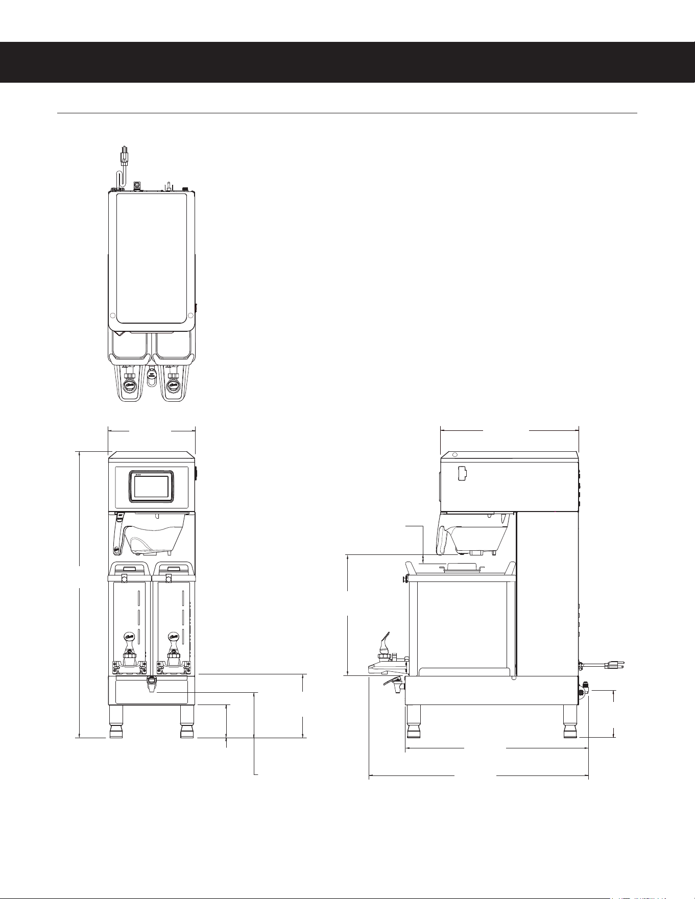
ROUGH-IN DRAWINGS RD112
G4GEMXN - Coffee Brewer
G4GEMXN, ROUGH-IN DRAWING 040720NC
4.00 in
[10.2 cm]
*CUP CLEARANCE
**WATER SUPPLY CONNECTION
16.78 in
[42.6 cm]
14.42 in
[36.6 cm]
5.48 in*
[13.9 cm]
5.75 in**
[14.6cm]
7.79 in*
[19.8 cm]
0.96 in
[2.4 cm]
22.04 in
[56.0 cm]
26.44 in
[67.2 cm]
10.50 in
[26.7 cm]
34.48 in
[87.6 cm]
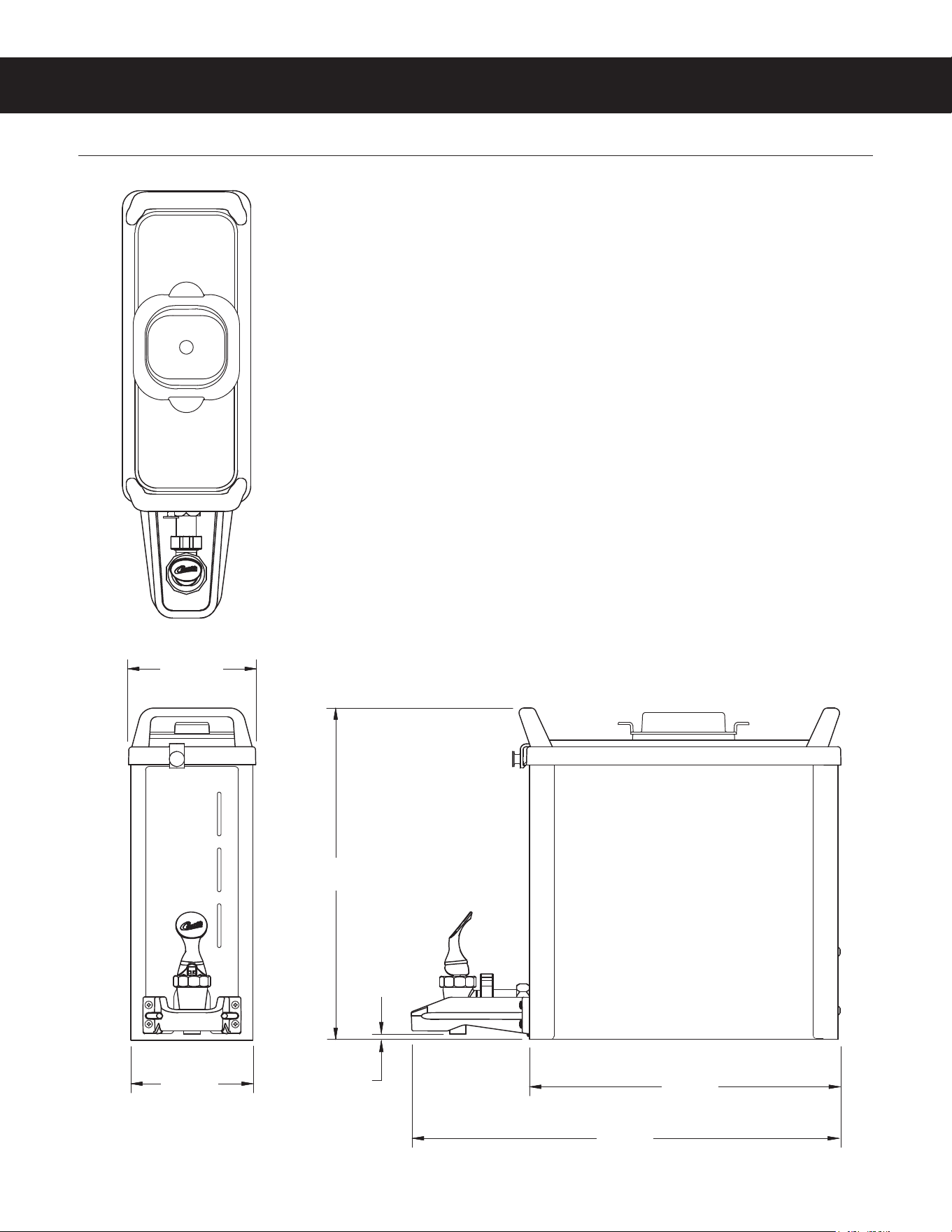
ROUGH-IN DRAWINGS RD113
GEM3XN - Dispenser
GEM3XN, ROUGH-IN DRAWING 040720NC
5.28 in
[13.4 cm]
5.02 in
[12.8 cm]
13.65 in
[34.7 cm]
12.79 in
[32.5 cm]
17.61 in
[44.7 cm]
0.25 in
[0.6 cm]
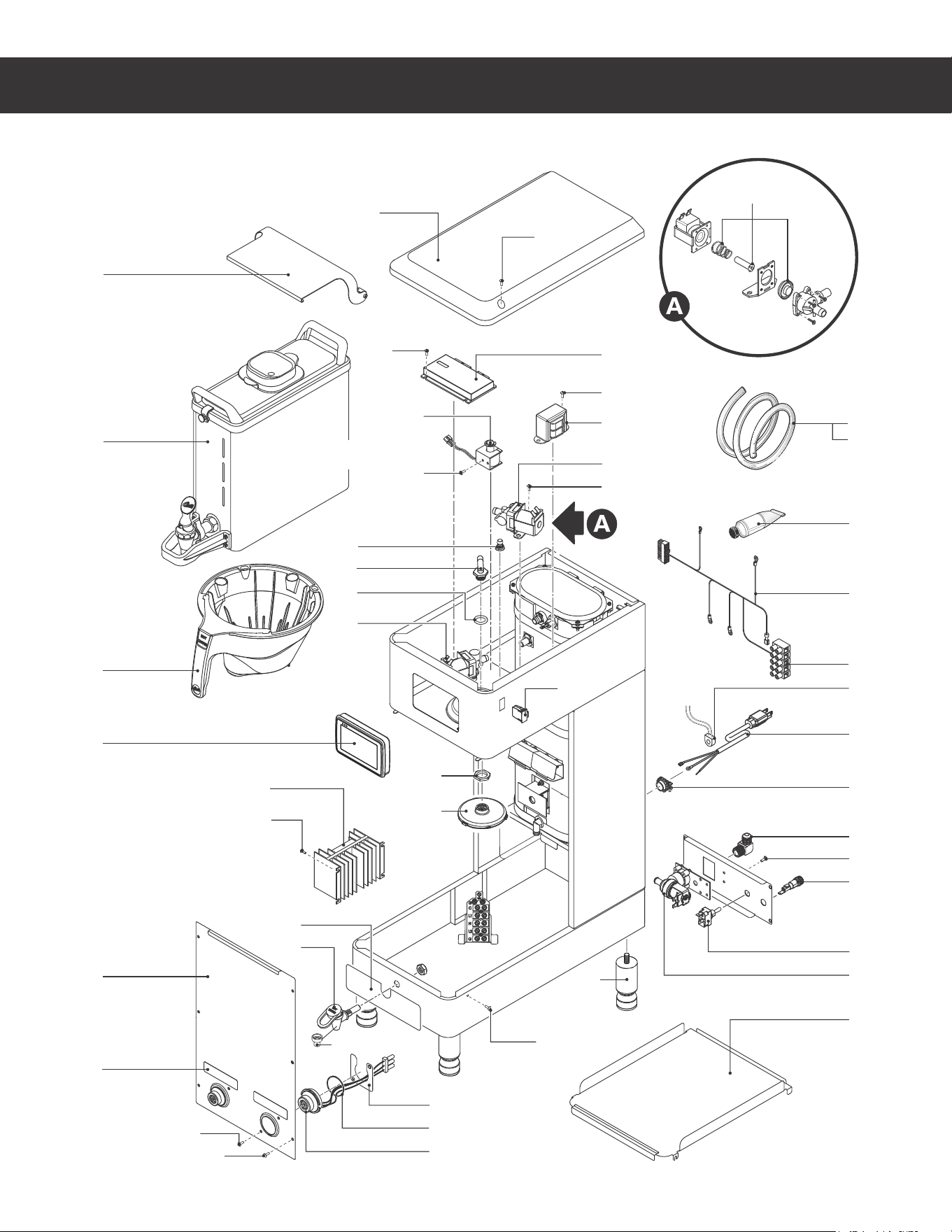
ILLUSTRATED PARTS LIST IP198
G4GEMXN - GENERIC, ILLUSTRATED PARTS/RECOMMENDED PARTS 042920NC
8
11
26
14
27
33
12
13
24
31
39
19
35
17
43
18
20
21
10
40
45
40
22
25
41
36
15
40
40
2
40
30
23
34
6
41
9
44
5
1
46
G4GEMXN - Main Chassis - Exploded View
Water tanks assemblies:
- 120/220 Volt, see section IP32
32
See satellite user guide for
satellite replacement parts.
42
28
4
29
3
40
16
7

ILLUSTRATED PARTS LIST IP198
G4GEMXN - GENERIC, ILLUSTRATED PARTS/RECOMMENDED PARTS 042920NC
ITEM # PART # DESCRIPTION
1 GEM3XN SATELLITE SERVER, NARROW
2 WC-66115 COVER, TOP GEMXSIFT
3 WC-820WDR
VALVE, DUMP RIGHT 120V 12W W/INTERNAL
RESISTOR & DIODE
4* WC-2977K KIT, SPRAYHEAD FITTING METAL
5 WC-3424 BREW CONE ASSY, ROTATE STYLE
6 WC-442
SOLENOID, LOCK BREW CONE RIGHT/LEFT
120V TP2T/TP2S/GEMSS/GEM
7 WC-844-101
VALVE, BY-PASS, NON-ADJUSTABLE WITH
RESTRICTOR (WC-2945)
8 WC-10000 CONTROL MODULE, TOUCH SCREEN G4
9 WC-10001 CONTROL MODULE, UPM 120/220V G4
10* WC-8559
RELAY, SOLID STATE 280V/40A W/ HEATSINK
AND QUICK DISCONNECTS
11 WC-58395-101 COVER, FRONT
12 WC-390610 LABEL, BOTTOM DECK G4GEMXN CURTIS
13* WC-1809-P
FAUCET, PS/HPS SERIES HOT WTR 1/2-20 UNF
AP/ALP
14 WC-61963 PLATE, HOLDER IF CONNECTORS GEMTIF
15* WC-3528
LEG, 4" ADJUSTABLE 3/8-16 THRD ITALIAN
STYLE
16 WC-589-101
TRANSFORMER,120VAC-24V 4.8A W/ LEADS &
MOLEX CONNECTOR
17* WC-2402P-P ELBOW, 3/8”FL x 3/8” NPT PLATED
18 WC-1501 FUSE, HOLDER ASSY W/5A FUSE
19 WC-14045-101 CURRENT SENSOR ASSY G4
20* WC-103
SWITCH, TOGGLE NON-LIT DPST 25A
125/250VAC RESISTIVE
21 WC-847*
VALVE, INLET 2 GPM 120V 10W GEN USE
BROWN BODY
22 WC-29050* SPRAYHEAD, AMBER ADVANCED FLOW
23 WC-5310* TUBE, 5/16 ID x 1/8W SILICONE
ITEM # PART # DESCRIPTION
24* WC-5231 COMPOUND, HEAT SINK 5OZ
25 WC-4213-P NUT, 5/8 LOCK PLATED
26 WC-38504
LABEL, WARNING SHOCK HAZARD INTELLI-
FRESH
27 WC-43133
O-RING, 1.424ID X 1.630 OD X .103 WALL
GEMIF’s
28 WC-29044-101 SLEEVE, OVERFLOW
29 WC-4320
O’RING, 0.487I.D.x 0.693OD x0.103CS BUNA-N
#112
30 WC-10008 UNIVERSAL HOST ADAPTER USB
31 WC-13536
HARNESS ASSY, COMPLETE G4GEMXN
(INCLUDES TERMINAL BLOCK)
32 WC-1412 CORD GRIP, 3/4” FOR METAL CORD TO .81”OD
33 WC-571K-R KIT, IF CONNECTOR- RIGHT
34 WC-5350 TUBE, 1/2 ID x 1/8W SILICONE GEN USE
35 WC-1200 CORD, 14/3 SJTO 6’ BLK W/PLUG
36 WC-65042-101 DECK, SATELLITE W/A
39 WC-314 POWER BLOCK, 5 STATION
40 WC-4426 SCREW, 8-32x3/8 PH HEAD TRUSS
41 WC-4514 SCREW, 8-32x3/8 PAN HEAD PH SS
42 WC-37132-101
KIT, VALVE REPAIR FOR DELTROL WC-820WDR,
WC-821WDR, WC-844WDR (NEWER UNITS)
43 WC-4616
SCREW, 1/4-20 x 1/2 PHILLIPS PAN HEAD
STAINLESS STEEL
44 WC-4412 SCREW, 10-32x3/16” PH PN HD MS SS
45 WC-1806 SEAT CUP, SILICONE USE ON WC-1809 FAUCET
46 WC-62098-102K
KIT COVER PIVOTING FRONT DISPLAY
(G4)GEMXSIFT (OPTIONAL ACCESSORY,
INCLUDES MOUNTING HARDWARE)
G4GEMXN - Main Chassis - Parts List
a
120/220 Volt units
b
220-240 Volt units
*Recommended parts to stock
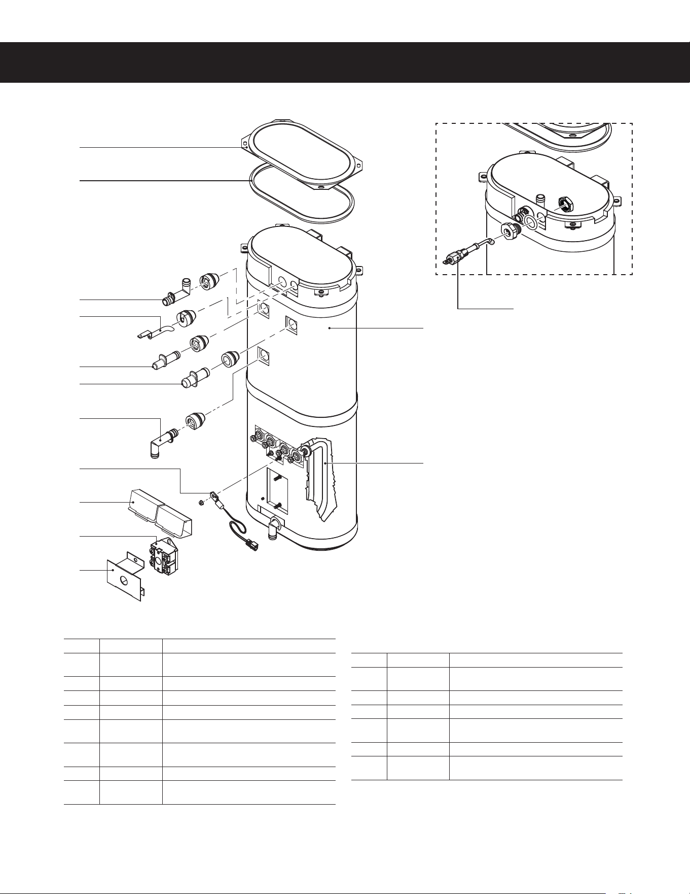
ILLUSTRATED PARTS LIST IP32
ITEM # PART # DESCRIPTION
1 WC-62034
TANK, COMPLETE GEMSS DV W/ ULTEM
FITINGS
2 WC-5853-102 COVER, TOP HEATING TANK GEN USE
3* WC-43062 GASKET, TANK LID
4A
1
WC-5528K KIT, WATER LEVEL PROBE, SILICONE
4B
2
WC-5502-01
KIT, PROBE, ASSY WATER LEVEL W/HEX FIT-
TING, O-RING & NUT
5* WC-904-04
KIT,ELEMENT, HEATING 1.6KW120V W/ JAM
NUT & SILICONE O-RING
6* WC-1438-101 SENSOR, TEMPERATURE TANK
7* WC-4394
GUARD, SHOCK/HEATING ELEMENT FOR SIN-
GLE HEATING ELEMENT
ITEM # PART # DESCRIPTION
8* WC-522
THERMOSTAT, HI LIMIT HEATER CONTROL
DPST 277V 40A
9* WC-43055 GUARD, SHOCK RESET THERMOSTAT (WC-522)
10* WC-37266 KIT, FITTING TANK OVERFLOW
11* WC-37317
KIT, STRAIGHT FITTING & BUSHNG 8mm GEN
USE
12* WC-37365 KIT, FITTING TANK INLET
13* WC-37357
KIT, STRAIGHT PLASTIC FITTING AND BUSHING
12MM
WC-62034 - Tank Assembly
2
3
10
4A
11
13
12
6
7
8
9
1
5
8$ø5"/,"44&.#-:*--6453"5&%1"3543&$0..&/%&%1"354 $
WC-62034 - Tank Assembly - Parts List
1
Units built 01/04/2019 and later.
2
Units built before 01/04/2019.Replaces WC-5527.
* Recommended parts to stock.
4B
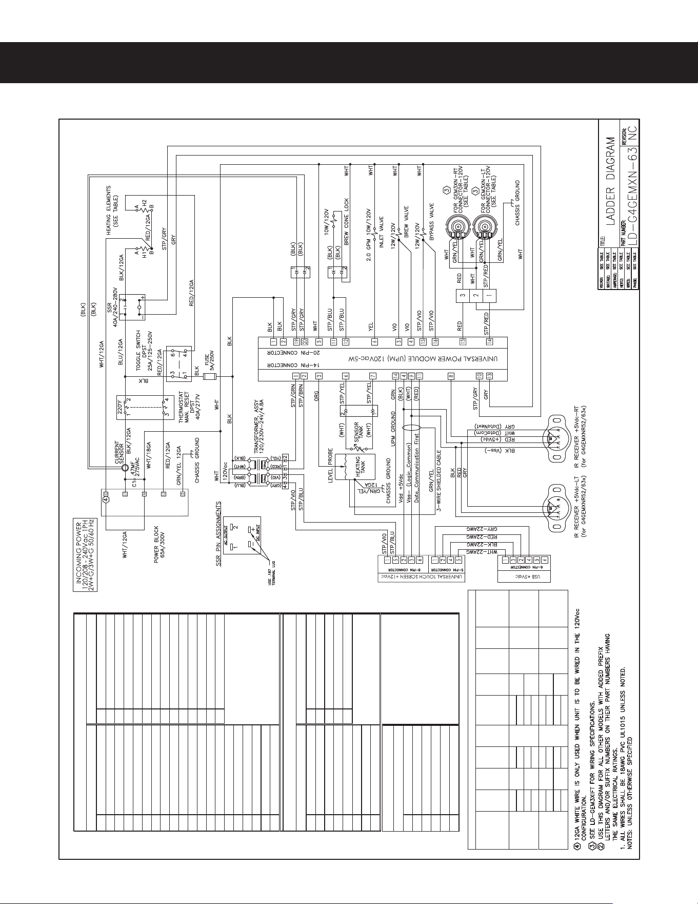
ELECTRICAL SCHEMATICS ES152
G4GEMXN-63, ELECTRICAL SCHEMATIC 042920NC
1
120Vac Hot Input
1
12 Vac Input
2
120Vac Hot Input
2
12 Vac Input
3
Brew Valve Right
3
Tank Wat er Level Probe
4
Brew Valve Left
4
Vdd +5Vdc
5
120Vac Neutral
5
Not Used
Not Used
6
Inlet Valve
6
Tank Temperature Sensor
7
Not Used
7
Tank Temperature Sensor
8
Not Used
8
Not Used
9
Triac Gate
9
Vss- (Logic_Common)
10
Triac A2
10
Solid State Relay +5Vdc
11
Brew Cone Lock Right
11
Data_Communication First
12
Brew Cone Lock Left
12
13
Warmer Right
13
Solid State Relay - Common
14
Warmer Le
ft
14
Tank Ground
15
Bypass Valv e Right
16
Bypass Valv e Left
17
Not Used
18
Not Used
19
Current Sensor
20
Current Sensor
1
12 Vac Input (Back Light)
1
TX - Transmit
2
Vdd +5Vdc
2
RX - Receive
3
Vss- (Logic_Common)
3
Not Used
4
Not Used
4
Vdd +5Vdc
5
12 Vac Input (Back Light)
5
Vss- (Logic_Common)
6
Dat a_Communicat ion First
7
Not Used
8
Not Used
1
Vss- (Logic_Common)
2
TX - Transmit
3
Vdd +5Vdc
4
RX - Receive
5
Not Used
6
Not Used
(UCM) Pin Assignments
USB Pin Assignments
6-Pin Connector
(UPM) Pin Assignments
rotcennoC niP 41rotcennoC niP 02
rotcennoC niP 5rotcennoC niP 8
Model
Voltage
V
Amps
A
WaƩs
W
Hertz
Hz
# of
Conductor
Wires
Phase
# of Tank
Elements
Tank
Element
RaƟng
W/V
Warmer
Element
RaƟng
W/V
120 1200 (2)
120/220 2050 3
120 1200 (2)
120/240 2400 3
120 1650 (2)
120/220 2800 3
120 1650 (2)
120/240 3300 3
ELECTRICAL RATING TABLE
G4GEMXN52x/
G4GEMXNR52x
10.0
50/60
1
2
1150W/
120V
(2X)
75W/120V
10.01
(2X)
75W/120V
15.31
G4GEMXN63x/
G4GEMXNR63x
13.5
50/60
1
2
1600W/
120V
G4GEMXN - Dual Voltage
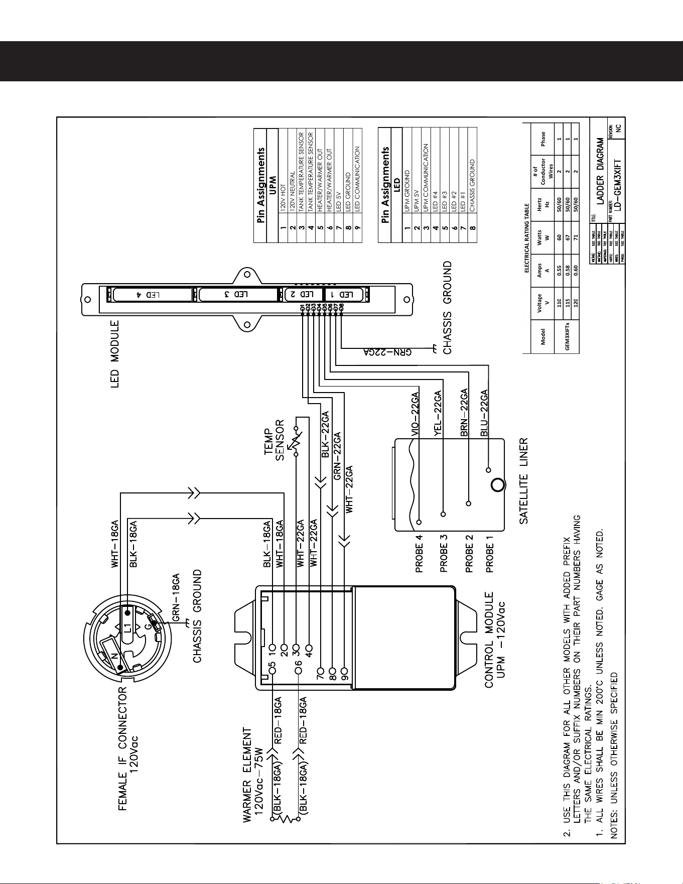
GEM3XIFT
ELECTRICAL SCHEMATICS ES108
(&.9*'5&-&$53*$"-4$)&."5*$ø "

WARNING:
Electric Shock Hazard - UIFGPMMPXJOHQSPDFEVSFTBSFUPCFQFSGPSNFEPOMZCZBRVBMJmFETFSWJDFUFDIOJDJBO
5VSO PGG QPXFS XIFO SFQMBDJOH DPNQPOFOUT /FJUIFS 8JMCVS $VSUJT $P *OD OPS UIF TFMMFS DBO CF IFME
SFTQPOTJCMFGPSUIFJOUFSQSFUBUJPOPGUIJTJOGPSNBUJPOPSBOZMJBCJMJUZJODPOOFDUJPOXJUIJUTVTF
Scald and Burn Hazard -LFFQCPEZQBSUTDMFBSPGIPUTVSGBDFTEVSJOHUSPVCMFTIPPUJOH
Troubleshooting Guidelines
• *GBOFSSPSNFTTBHFBQQFBSTPOUIFEJTQMBZDPOTVMUUIF&3303$0%&4TFDUJPOCFGPSFUSPVCMFTIPPUJOH
• "CSFXFSUIBUJTOPUMFWFMNBZOPUGVODUJPOQSPQFSMZ.BLFTVSFUIFCSFXFSJTQSPQFSMZMFWFMFECFGPSF
QSPDFFEJOH
• 5IJTUSPVCMFTIPPUJOHHVJEFJEFOUJmFTTPNFCVUOPUBMMPGUIFQPTTJCMFDBVTFTGPSDPNNPOQSPCMFNTUIBUDBO
PDDVS
• 6TFUIJTUSPVCMFTIPPUJOHHVJEFBMPOHXJUIUIFBQQSPQSJBUF&-&$53*$"-4$)&."5*$.
Valve Test Procedure
6TFBEJHJUBMNVMUJNFUFSUPNFBTVSFUIFSFTJTUBODFPGWBMWFDPJMT
.FBTVSFUIFSFTJTUBODFBDSPTTUIFWBMWFDPJMUFSNJOBMTXJUIUIFXJSJOHIBSOFTTEJTDPOOFDUFE3FWFSTFUIFNFUFS
MFBETPOUIFUFSNJOBMTBOENFBTVSFUIFSFTJTUBODFJOUIFPQQPTJUFEJSFDUJPO"SFTJTUBODFPGMFTTUIBOPINT
in either directionJOEJDBUFTBTIPSUFEDPJM5IFWBMWFNVTUCFSFQMBDFE
*GBTIPSUFEDPJMJTOPUEFUFDUFEUFTUGPSBOPQFODPJM
3FDPOOFDUUIFWBMWFUFSNJOBMTUPUIFXJSJOHIBSOFTT
2 1PXFSVQUIFCSFXFSBOEUFTUUIFWBMWFVTJOHUIFEJBHOPTUJDTJOTFDUJPO5(
Water Not Hot Enough
*GUIFXBUFSIFBUTCVUJTOPUIPUFOPVHImSTUDIFDLGPSUIFDPSSFDUUFNQFSBUVSFTFUUJOHPOUIFDPOUSPMQBOFM
3FQSPHSBNBTOFDFTTBSZ
2 *GUIFUFNQFSBUVSFTFUUJOHJT0,BOEUIFBDUVBMXBUFSUFNQFSBUVSFEPFTOPUNBUDITFUUJOHPOUIFDPOUSPMQBOFM
replace the temperature sensor
Water Heats More Slowly Than Usual
$IFDLGPSQPXFSBDSPTTUIFUFSNJOBMTPGUIFIFBUJOHFMFNFOUT*GQPXFSJTCFJOHTVQQMJFEEJTDPOOFDUUIFIFBUJOH
FMFNFOUTBOEDIFDLGPSDPOUJOVJUZ3FQMBDFBIFBUJOHFMFNFOUJGUIFSFTJTUBODFJTUPPIJHIOPNJOBMSFTJTUBODFJT
0INT
2 *GUIFSFJTOPQPXFSUPUIFIFBUJOHFMFNFOUTDIFDLUIFXJSJOHUPBOZFMFNFOUUIBUEPFTOPUIBWFUIFQSPQFS
WPMUBHFBDSPTTJU"MTPDIFDLGPSDPSSPEFEDPOOFDUJPOTBOZXIFSFCFUXFFOUIFQPXFSDPSEBOEUIFIFBUJOH
FMFNFOUT
'LVSHQVHU2YHUÁRZVDuring Brewing
$IFDLUPNBLFTVSFUIFDPOUSPMNPEVMF6$.CSFXCZQBTTBOEEJMVUJPOMFWFMTBSFTFUQSPQFSMZ
2 $IFDLGPSBNJTTJOHTQSBZIFBE3FQMBDFBTOFFEFE
.BLFTVSFUIFEJTQFOTFSJTFNQUZCFGPSFTUBSUJOHUIFCSFXDZDMF*GOPUFNQUZJUCFGPSFCSFXJOH
4PNFVOJUTEPOPUIBWFUIJTGVODUJPOTFFUIF&-&$53*$"-4$)&."5*$
TROUBLESHOOTING GUIDE TG3
(#3&8&345306#-&4)005*/((6*%& "
IMPORTANT: *GJUJTOFDFTTBSZUPSFQMBDFUIF(VOJWFSTBMQPXFSNPEVMF61.always check allJOMFU
EVNQ CSFX CZQBTT BOE EJMVUJPO WBMWF DPJMT GPS B TIPSU BOE SFQMBDF UIF WBMWF BT OFDFTTBSZ CFGPSF
SFQMBDJOHUIFNPEVMF4FFUIFValve Test ProcedureCFMPXUPUFTUGPSEFGFDUJWFWBMWFT4PNFVOJUTEPOPU
IBWFUIJTGVODUJPOTFFUIF&-&$53*$"-4$)&."5*$

TROUBLESHOOTING GUIDE TG3
(#3&8&345306#-&4)005*/((6*%& "
No Power - Display Not Lit
.BLFTVSFUIFDJSDVJUCSFBLFSUPUIFDJSDVJUTVQQMZJOHQPXFSUPUIFCSFXFSJTOPUUSJQQFEBOEJTUVSOFEPO
2 0OCSFXFSTXJUIBQPXFSQMVHNBLFTVSFJUJTDPOOFDUFEUPUIFQPXFSSFDFQUBDMF
.BLFTVSFUIBUUIFNBJOQPXFSUPHHMFTXJUDIPOUIFCBDLQBOFMJTUVSOFE0/
7FSJGZUIBUBMMXJSFTGSPNUIFQPXFSDPSEBSFQSPQFSMZDPOOFDUFEJOTJEFUIFVOJU$IFDLUPNBLFTVSFUIFXJSFT
BSFOPUCVSOFEPWFSIFBUFE$IFDLDIBTTJTHSPVOE
5 $IFDLUIFMPXWPMUBHFJOQVUUPUIFVOJWFSTBMDPOUSPMNPEVMF6$.GSPNUIFUSBOTGPSNFSTFFUIF&-&$53*$"-
4$)&."5*$*GUIFSFJTQPXFSJOUPUIF6$.CVUUIFEJTQMBZJTCMBOLUIF6$.JTQSPCBCMZCBE
6 *GUIFSFJTOPQPXFSJOUPUIF6$.USBDFUIFDJSDVJUCBDLVTJOHUIFXJSJOHEJBHSBNUPUIFQPXFSDPSEUPmOE
PVUXIFSFQPXFSJTMPTU*GUIFSFJTQPXFSJOUPUIFUIFSNPTUBUSFTFUTXJUDICVUOPUPVUTFFTUFQ
*GUIFSFJTQPXFSJOUPUIFUIFSNPTUBUSFTFUTXJUDICVUOPUPVUDIFDLUPNBLFTVSFUIBUUIFXBUFSUBOLJTOPU
FNQUZ*GUIFUBOLJTFNQUZUIFSFTFUTXJUDIIBTQSPCBCMZPQFOFEVQEVFUPBMPXXBUFSMFWFMHPUPWater
Tank Does Not Fill*GUIFSFJTXBUFSJOUIFUBOLCVUOPQPXFSPVUQVTIJOPOUIFSFTFUTXJUDICVUUPOUPTFF
JGJUSFTUPSFTQPXFS*GQPXFSJTSFTUPSFEDIFDLUPNBLFTVSFUIBUUIFTXJUDIJTOPUPQFOJOHVQBUUIFXSPOH
UFNQFSBUVSFUIFTXJUDITIPVMEOPUPQFOVQBUOPSNBMXBUFSUFNQFSBUVSFT*GUIFSFJTTUJMMOPQPXFSUISPVHIUIF
TXJUDIBGUFSQVTIJOHUIFCVUUPOSFQMBDFUIFUIFSNPTUBUSFTFUTXJUDI
Brewer Does Not Start When Brew Button is Pressed
*GBrewingBQQFBSTPOUIFEJTQMBZDIFDLGPSGBVMUZXJSJOHBOEDPOOFDUJPOTCFUXFFOUIFVOJWFSTBMQPXFS
NPEVMF61.BOEUIFWBMWFT
2 *GBrewingEPFTOPUBQQFBSPOUIFEJTQMBZDIFDLGPSBGBVMUZVOJWFSTBMDPOUSPMNPEVMF6$.PSVOJWFSTBM
QPXFSNPEVMF61.
Sensor Error Message
5IJTFSSPSJOEJDBUFTBNBMGVODUJPOPQFODJSDVJUJOUIFUFNQFSBUVSFTFOTPSTZTUFN0ODFUIFNBMGVODUJPOJT
DPSSFDUFEUIFFSSPSNFTTBHFNVTUCFDMFBSFE5PSFTFUUIFCSFXFSBOESFUVSOUPOPSNBMPQFSBUJPOUVSOUIFUPHHMF
TXJUDIPOUIFCBDLPGUIFCSFXFSUPUIF0''QPTJUJPOGPSTFDPOETUIFOCBDL0/
$IFDLUIFSFTJTUBODFBDSPTTUIFMFBETPGUIFUFNQFSBUVSFTFOTPSXIJMFJUJTEJTDPOOFDUFEGSPNUIFVOJWFSTBM
QPXFSNPEVMF61.*GBOPQFODJSDVJUJTNFBTVSFESFTJTUBODFBCPWFLSFQMBDFUIFTFOTPS
2 *GUIFTFOTPSSFTJTUBODFJTMFTTUIBOLDIFDLUIFTFOTPSXJSFTGPSDPSSPTJPOBOESFDPOOFDUUIFNUPUIF
61."GUFSXBSEJGUIFFSSPSNFTTBHFDPNFTCBDLBGUFSSFTFUUJOHUIFDPOUSPMBOEQPXFSNPEVMFTSFQMBDFUIF
61.
:DWHU7DQN2YHUÀOOV
5VSOUIFUPHHMFTXJUDIPOUIFCBDLPGUIFCSFXFS0/BOE0''*GXBUFSDPOUJOVFTUPnPXXIFOUIFTXJUDIJTJO
CPUIQPTJUJPOTSFQMBDFUIFJOMFUWBMWF
2 *GXBUFSTUPQnPXJOHUPUIFXBUFSUBOLXIFOUIFUPHHMFTXJUDIJTUVSOFE0''BOEDPOUJOVFTXIFOUIFTXJUDI
JTUVSOFECBDL0/SFNPWFUIFPSBOHFXJSFGSPNUIFXBUFSQSPCFPOUIFUBOL8IJMFQPXFSJT0/TIPSUUIF
FOEPGUIFPSBOHFXJSFUPUIFNFUBMTVSGBDFPOUIFPVUTJEFPGUIFUBOL*GUIFXBUFSUBOLTUPQTmMMJOHXIFOUIF
PSBOHFXJSFJTTIPSUFEUPUIFUBOLDIFDLGPSBDPSSPEFEDPOOFDUJPOBUUIFXBUFSQSPCF
*GXBUFSEPFTOPUTUPQnPXJOHXIFOUIFPSBOHFXJSFJTTIPSUFEUPUIFUBOLDIFDLUIFUBOLHSPVOEDPOOFDUJPO
BOEUIFDPOUJOVJUZPGUIFPSBOHFXJSFDPOOFDUJOHUPUIFVOJWFSTBMQPXFSNPEVMF61.*GCPUIBSF0,SFQMBDF
UIF61.

Water Tank Does Not Fill
$IFDLUPNBLFTVSFUIFXBUFSTVQQMZJTUVSOFEPO$IFDLGPSBQMVHHFEXBUFSTVQQMZMJOFPSQMVHHFEJOMFU
WBMWF
2 *GUIFSFBSFOPQMVHTJOUIFXBUFSTVQQMZMJOFDIFDLGPSQPXFSBDSPTTUIFJOMFUWBMWFUFSNJOBMT*GQPXFSJTCFJOH
TVQQMJFECVUUIFSFJTOPXBUFSnPXSFQMBDFUIFJOMFUWBMWF
*GQPXFSJTOPUCFJOHTVQQMJFEUPUIFJOMFUWBMWFDIFDLUIFXJSFTCFUXFFOUIFVOJWFSTBMQPXFSNPEVMF61.
BOEUIFJOMFUWBMWF$IFDLGPSDPSSPEFEDPOOFDUJPOT
*GUIFXJSJOHCFUXFFOUIF61.BOEUIFJOMFUWBMWFJT0,CVUUIFSFJTOPQPXFSUPUIFJOMFUWBMWFSFNPWFUIF
PSBOHFXJSFGSPNUIFXBUFSUBOLQSPCF*GUIFXBUFSUBOLTUBSUTUPmMMSFQMBDFUIFXBUFSQSPCF*GUIFXBUFSUBOL
EPFTOPUTUBSUUPmMMSFQMBDFUIF61.
Coffee/Tea Too Strong
4FFDispenser Not Filled To Normal Level During Brewing
Dispenser Not Filled To Normal Level During Brewing
$IFDLUPNBLFTVSFUIBUUIFVOJWFSTBMDPOUSPMNPEVMF6$.CSFXCZQBTTBOEEJMVUJPOMFWFMTBSFTFU
QSPQFSMZ
2 $IFDLUPNBLFTVSFUIBUUIFnPXSBUFBOEXBUFSQSFTTVSFGSPNUIFXBUFSTVQQMZMJOFNFFUUIFNJOJNVN
TQFDJmDBUJPOTGPSUIFCSFXFS4FFUIF41&$*'*$"5*0/4TFDUJPO
$IFDLUPNBLFTVSFUIBUUIFTQSBZIFBEJTDMFBOBOEGSFFPGEFCSJT$MFBOPSSFQMBDFBTOFFEFE"MTPNBLF
sure that the spray head is correctly aligned and that the tubing is routed properly to allow for maximum water
nPXOPLJOLT
3FNPWFUIFCSFXCBTLFUBOEQMBDFBMBSHFDPOUBJOFSVOEFSUIFEVNQCSFXBOEEJMVUJPOPVUMFUQPJOUT3VOB
CSFXDZDMFBOEDPOmSNUIBUUIFEVNQCSFXWBMWFCZQBTTWBMWFBOEEJMVUJPOWBMWFPQFOEVSJOHUIFCSFX
DZDMF$IFDLGPSnPXUISPVHIBOZFYJUQPJOUUIBUJTTMPXPSOPOFYJTUFOU/PUBMMWBMWFTPQFOBUUIFTBNFUJNF
*GnPXJTSFTUSJDUFEDIFDLGPSPCTUSVDUJPOTJOUIFSFMBUFEUVCJOHPSWBMWF*GUIFSFBSFOPPCTUSVDUJPOTCVUnPX
UISPVHIPOFQBSUJDVMBSWBMWFJTTMPXJUDBOCFBTTVNFEUIBUUIFQBSUJDVMBSWBMWFJTOPUPQFOJOHBMMUIFXBZBOE
TIPVMECFSFQMBDFE*GXBUFSEPFTOPUnPXBUBMMUISPVHIBQBSUJDVMBSWBMWFEVSJOHUIFCSFXDZDMFDIFDLUP
NBLFTVSFUIBUQPXFSJTCFJOHTVQQMJFEUPUIFWBMWFJORVFTUJPO3FQMBDFBOZWBMWFUIBUJTOPUPQFOJOHXIFO
QPXFSJTBQQMJFEUPUIFUFSNJOBMT*GQPXFSJTOPUCFJOHTVQQMJFEUPUIFWBMWFDIFDLUIFXJSJOHCFUXFFOUIF
WBMWFBOEUIFVOJWFSTBMQPXFSNPEVMF61.*GUIFXJSJOHJT0,SFQMBDFUIF61.
4PNFVOJUTEPOPUIBWFUIJTGVODUJPOTFFUIF&-&$53*$"-4$)&."5*$
'LVSHQVHU2YHUÁRZVAll Of The Time
$IFDLUPTFFJGXBUFSDPOUJOVFTUPnPXGSPNUIFTQSBZIFBEUIFCZQBTTPVUMFUPSUIFEJMVUJPOTQPVUXIFOUIF
UPHHMFTXJUDIJTUVSOFE0''3FQMBDFBOZWBMWFUIBUJTTUVDLPQFO
4PNFVOJUTEPOPUIBWFUIJTGVODUJPOTFFUIF&-&$53*$"-4$)&."5*$
2 *GPOFPSNPSFPGUIFWBMWFTNFOUJPOFEJOTUFQUVSOTPOXIFOUIFUPHHMFTXJUDIPOUIFCBDLJT0/BOEUVSOT
PGGXIFOUIFTXJUDIJT0''SFQMBDFUIFVOJWFSTBMQPXFSNPEVMF61.
TROUBLESHOOTING GUIDE TG3
(#3&8&345306#-&4)005*/((6*%& "
IMPORTANT: /PXBUFSPSMPXXBUFSJOUIFUBOLDBODBVTFUIFUBOLUPPWFSIFBUSFTVMUJOHJOUIFUIFSNPTUBU
SFTFUTXJUDIPQFOJOH*GBGUFSDPSSFDUJOHBUBOLmMMQSPCMFNUIFSFJTOPQPXFSUPUIFDPOUSPMQBOFMQVTIUIF
SFTFUTXJUDICVUUPOUPSFTFU

No Water/Tea Flows From Brewer During Brewing
.BLFTVSFUIBUUIFXBUFSTVQQMZJTUVSOFEPO
2 $IFDLUPTFFJGUIFXBUFSJOUIFUBOLJTMFWFMXJUIUIFXBUFSUBOLQSPCF *GOPUTFFWater Tank Does Not Fill
*GUIFXBUFSUBOLJTGVMMUIFXBUFSJTIPUBOEQPXFSJTPOCVU/0XBUFSnPXTEVSJOHBCSFXDZDMFUIFQSPCMFN
JTVTVBMMZBCBEVOJWFSTBMQPXFSNPEVMF61.3VOBCSFXDZDMFBOEDIFDLGPSQPXFSGSPNUIF61.UPUIF
EVNQCSFXCZQBTTBOEEJMVUJPOWBMWFT*GUIFSFJTOPQPXFSPVUQVUSFQMBDFUIF61.
4PNFVOJUTEPOPUIBWFUIJTGVODUJPOTFFUIF&-&$53*$"-4$)&."5*$
Low Water Flow Warning
4FFWater Level Error Message
Water Level Error Message
8BUFSMFWFMmMMFSSPSPSPWFSnPX5IJTFSSPSNFTTBHFPDDVSTXIFOUIFJOMFUWBMWFTPMFOPJEIBTCFFOPOUPPMPOH
EVSJOHJOJUJBMmMMPSUBOLSFmMM4FFUIF&3303$0%&4TFDUJPOGPSUIFNBYJNVNUJNFTBMMPXFE0ODFUIFNBMGVODUJPO
JTDPSSFDUFEUIFFSSPSNFTTBHFNVTUCFDMFBSFE5PSFTFUUIFVOJUBOESFUVSOUPOPSNBMPQFSBUJPOUVSOUIFUPHHMF
TXJUDIPOUIFCBDLPGUIFCSFXFSUPUIF0''QPTJUJPOGPSTFDPOETUIFOCBDL0/
$IFDLUPNBLFTVSFUIBUUIFnPXSBUFGSPNUIFXBUFSTVQQMZMJOFNFFUTUIFNJOJNVNnPXSBUFTQFDJmDBUJPOTGPS
UIFCSFXFS"MTPDIFDLUIFXBUFSQSFTTVSF4FFUIF41&$*'*$"5*0/4TFDUJPO
2 $IFDLGPSCMPDLBHFBUUIFJOMFUWBMWFJOMFUPSPVUMFU$IFDLGPSCMPDLBHFJOUIFUVCJOHCFUXFFOUIFJOMFUWBMWF
BOEUIFXBUFSUBOL
$IFDLUIFXBUFSQSPCFXJSFGPSBOPQFODPOEJUJPOPSDPSSPEFEDPOOFDUJPOT
*GUIFQSPCFDPOOFDUJPOTBSF0,DZDMFQPXFSUPUIFVOJUCZUVSOJOHUIFSFBSUPHHMFTXJUDI0''UIFO0/
$IFDLUPTFFJGQPXFSJTBQQMJFEUPUIFJOMFUWBMWFUFSNJOBMT*GQPXFSJTBQQMJFEUPUIFUFSNJOBMTCVUUIFSFJTOPU
XBUFSnPXSFQMBDFUIFJOMFUWBMWF
5 $IFDLGPSQPXFSGSPNUIFVOJWFSTBMQPXFSNPEVMF61.UPUIFJOMFUWBMWF*GUIFXJSJOHJT0,SFQMBDFUIF
61.
“Internal Error 1” Message on Display
$IFDLUIFXJSJOHIBSOFTTUIBUDPOOFDUTGSPNQJOTBOEPGUIFQJODPOOFDUPSPOUIFVOJWFSTBMQPXFS
NPEVMF61.UPQJOTBOEPGUIFQJODPOOFDUPSPOUIFVOJWFSTBMDPOUSPMNPEVMF6$.
“Internal Error 2” Message on Display
5IFVOJWFSTBMQPXFSNPEVMF61.BOEVOJWFSTBMDPOUSPMNPEVMF6$.IBWFBNJTNBUDIJOUIFJSTFUUJOHT"
mSNXBSFVQEBUFJTOFFEFE4FFPROGRAMMING GUIDE
TROUBLESHOOTING GUIDE TG3
(#3&8&345306#-&4)005*/((6*%& "

TROUBLESHOOTING GUIDE TG7
G4 BREWERS WITH SSR, TROUBLESHOOTING GUIDE 122717A
Water Does Not Heat At All
• Check to see if the water level in the tank is in contact with the water level probe. If not, see Tank Does Not Fill.
The water will not heat unless it is in contact with the probe.
• If the water heats, but is not hot enough, see Water Not Hot Enough.
• If Ready to brew appears on the display, but the water is not hot, check the resistance across the leads of the
temperature sensor. If the resistance is less than 10 k and the water is not hot, replace the temperature sensor.
If the sensor resistance is above 10 k when the water is cool, replace the universal power module (UPM).
If Heating... appears on the display, but the water is not hot, follow the steps below. The following steps are
performed with the rear toggle switch in the ON position.
1 Check for power across the terminals of the heating element(s). If power is being supplied, remove the wires
and check for an open heating element.
2 If there is no power to the element(s), trace the circuit back (using the ELECTRICAL SCHEMATIC) to the power
DPSEUPmOEPVUXIFSFQPXFSJTMPTU*GUIFSFJTQPXFSJOUPUIFTPMJETUBUFSFMBZT443TCVUOPUPVUTFFUIF
following step. On units having two SSRs, be sure to check both.
3 If there is power into a SSR, but not out, check for 5 Vdc (nominal*) across the + and - pins of the SSR(s). If
there is 5 Vdc across the + and - pins of the SSR(s), but no (or low) output voltage at a SSR output terminal,
replace the SSR. If 5 Vdc is not being supplied from the UPM, but Heating... appears on the display, check
the wiring from the UPM to the SSR(s). If the wiring is OK, replace the UPM.
Water Too Hot (Boiling or Excessive Steaming)
1 If Over Temp Sensor or Ready to Brew appears on the display and the water is too hot, go to Over Temp
Sensor Error Message.
2 If the display reads HeatingDPOTUBOUMZmSTUDIFDLUPNBLFTVSFUIBUUIFUFNQFSBUVSFTFOTPSJTBUUBDIFEUJHIUMZ
to the tank and that heat sink compound was used. A properly mounted sensor should have a resistance of
around 7 k when the water is hot. If not, replace the sensor.
3 Check to see if the universal power module (UPM) constantly has +5 Vdc (nominal) output to the solid state
relay (SSR), regardless of the resistance of the temperature sensor. If so, the UPM is probably bad.
4 If the UPM is working properly, check for a shorted SSR.
Over Temp Sensor Error Message
This error message indicates that the universal control module (UCM) has detected a water overheating
problem. The universal power module (UPM) is reading a water temperature in the tank above 210ºF. If the water
temperature is too hot, but Heating... appears on the display, see Water Too Hot. Once the malfunction causing
the error is corrected, the error message must be cleared. To reset the brewer and return to normal operation, turn
the toggle switch on the back of the brewer to the OFF position for 5 seconds, then back on.
1 Check for 5 Vdc (nominal) across the + and - pins of the solid state relay (SSRs). If no power is applied to the
SSR and the heating elements are always on, replace the SSR. On units having two SSRs, check both.
2 Turn off power to the brewer and allow the water tank to cool. Once cool, turn power back on while monitoring
the voltage across the + and - pins of the SSR(s). During normal operation, the voltage should be 5 Vdc,
until the water is hot, then drop to below 1 Vdc. The universal power module (UPM) should be replaced if the
voltage reads 5 Vdc constantly even though Ready to brew or Over Temp Sensor appears on the display.
3 If the UPM is operating normally, check for a false over-temp error caused by the temperature sensor. Check
the resistance across the leads of the temperature sensor. If the resistance is less than 10 k when the water is
cool, replace the temperature sensor.
IMPORTANT: Before proceeding, make sure that the control panel temperature is adjusted to compensate
for higher elevations. The factory setting is 200°F. Reduce the temperature setting two degrees for every
1000 feet of elevation above 4000 feet.
TROUBLESHOOTING GUIDE TG35
Dispenser Does Not Heat
NOTE5IFEJTQFOTFSIFBUJOHFMFNFOUJTEFTJHOFEUPLFFQCSFXFEDPGGFFIPUCVUJTOPUPGTVGmDJFOUXBUUBHFUP
reheat cold coffee.
1 First check to see if one of the LED bars on the
EJTQFOTFSJTnBTIJOHBOFSSPSDPEF5IFUPQ-&%CBS
nBTIJOHSFEJOEJDBUFTBCBEIFBUJOHFMFNFOU5IF
NJEEMF-&%CBSnBTIJOHSFEJOEJDBUFTBEFGFDUJWF
sensor circuit on the controller (replace the controller).
2 Check to see if the Intellifresh
®
LED on the front of
the dispenser comes on at the beginning of the brew
cycle. If neither the LED nor the warmer come on,
then it can be assumed that there is no power to the
dispenser. Make sure that power is being supplied to
the Intellifresh (IF) connector on the brewer when the
#3&8CVUUPOJTQSFTTFE5IFWPMUBHFWBSJFTCBTFE
on the model, see the ELECTRICAL SCHEMATIC. If
power is present at the connector, check the connector
contacts. If power is not present at the IF connector,
trace the circuit back to the control module to see if it is
supplying power to the IF connector.
3 Check the contacts on the dispenser IF connector to make sure that they are making good contact with the
connector on the brewer.
4 *GUIFEJTQFOTFSJTSFDFJWJOHQPXFSGSPNUIF*'DPOOFDUPSBOEUIFSFBSFOPFSSPSDPEFTTVTQFDUUIFDPOUSPMMFS
None of the LED Bars Light, Regardless of Coffee Level (Warmer is Working OK)
NOTE: If the dispenser is empty, the LED bars will not light.
1 Check for chassis ground, UPM ground and UPM 5 Volts into the LED array (see LED pin assignment on
dispenser schematic).
2 If power and ground are being supplied to the LED array and none of the LED sections come on when the
dispenser is full, the LED array is probably bad.
Some LED Bars Do Not Light
Short the probe wire for the LED section that is not working to ground. If the section lights, check the probe
connection. If the section does not light, the LED array is bad.
One or More LED Bars are Constantly On Regardless of Coffee Level
1 Clean the inside of the dispenser according to the CLEANING INSTRUCTIONSTFDUJPOUPSFNPWFBOZSFTJEVF
build-up that may be causing a malfunction.
2 Check for a probe wire that is shorted to ground.
3 If the probe wires are OK, suspect the LED array.
IntelliFresh Feature Does Not Work (Warmer OK)
1 Check to make sure that the UCM IntelliFresh settings on the brewer are correct.
2 Check the continuity of the UPM/LED communication wire.
3 Replace the LED module. If the IntelliFresh feature does not work properly after replacing the LED module, the
dispenser UPM module is probably bad.
GEMXIFT INTELLIFRESH SATELLITE, TROUBLESHOOTING GUIDE 060820C
7RSVHJPHQWÀDVKLQJ
EDGKHDWLQJHOHPHQW
0LGGOHVHJPHQWÀDVKLQJ
GHIHFWLYHFRQWUROOHU
TROUBLESHOOTING GUIDE TG11
Overview
The G4 control module diagnostics can be used to detect electrical circuit failures in the brewer. When a circuit
GBJMVSFJTJEFOUJmFEUIFJOEJWJEVBMDPNQPOFOUTBOEXJSJOHJOUIFDJSDVJUNVTUCFDIFDLFEUPEFUFSNJOFUIFFYBDU
DBVTFPGUIFGBJMVSFVTJOHUIF&-&$53*$"-4$)&."5*$*GBGBJMVSFJTOPUEFUFDUFEVTJOHUIFEJBHOPTUJDT
USPVCMFTIPPUUIFQSPCMFNBDDPSEJOHUPUIFTZNQUPNTMJTUFEJOPUIFSTFDUJPOTPGUIJT5306#-&4)005*/((6*%&
5IFEJBHOPTUJDTDBOBMTPCFVTFEUPIFMQEJBHOPTFDFSUBJONFDIBOJDBMGBJMVSFT4FFUIFGPMMPXJOHTUFQT
(%*"(/045*$45306#-&4)005*/((6*%& A
Using the Diagnostics
&OUFSQSPHSBNNJOHNPEFCZUBQQJOHUIFXIJUF$VSUJT
MPHPPOUIFUPVDITDSFFOmWFUJNFT
&OUFSUIFBDDFTTDPEFUIFOQSFTTOKUIFEFGBVMUDPEF
JT
The MAIN MENUTDSFFOXJMMBQQFBS1SFTTControl
Settings.
4 1SFTTDiagnostics8IFOQSPNQUFEQMBDFBOFNQUZ
DPOUBJOFSVOEFSUIFCSFXCBTLFUUIFOQSFTTOK.
1SFTTBCVUUPOUPUFTUUIFEFTJSFEDJSDVJUPSAuto Test
to test all circuits. If a button is highlighted green the
DJSDVJUIBTQBTTFEUIFFMFDUSJDBMUFTU*GUIFCVUUPOJT
IJHIMJHIUFESFEUIFDJSDVJUIBTGBJMFEUIFUFTU
*GUIFDJSDVJUUFTUFEGBJMTDIFDLUPNBLFTVSFUIBUQPXFS
JTCFJOHTVQQMJFEUPUIFDPNQPOFOUEVSJOHOPSNBM
PQFSBUJPO*GQPXFSJTTVQQMJFEBOEJUEPFTOPUPQFSBUF
SFQMBDFUIFDPNQPOFOU*GQPXFSJTOPUCFJOHTVQQMJFE
DIFDLUIFXJSJOHBOEUIF61.
*GBWBMWFDJSDVJUQBTTFTUIFUFTUDIFDLGPSBNFDIBOJDBM
GBJMVSFCZMJTUFOJOHGPSUIFWBMWFUPiDMJDLwXIFOUIFUFTU
CVUUPOJTQSFTTFE5PDIFDLGPSBGBJMFEQVNQSVOB
CSFXDZDMFBOEDIFDLGPSnVJEnPXUISPVHIUIFQVNQ
DIAGNOSTICS
Auto TestLeft Right
Inlet ValveDump Vavle Dump Vavle
Heating SystemCone Lock Cone Lock
Level ProbeBypass Valve Bypass Valve
PumpWarmer Warmer
Curtis logo
Diagnostics Screen
Button layout varies based on model
Display view varies
with model

ERROR CODES EC1
Warning Messages - Allows Brewer to Continue Brewing
MESSAGE DISPLAY WARNING DESCRIPTION CAUSE
Maintenance Required Maintenance Required
Brew count “Gallons Since Reset” exceeds programmed
preventative maintenance period.
Low Water Flow
Warning
Low Water Flow
If the Inlet valve remains on longer than XX seconds (during
the brew cycle only) and repeats TWICE during that brew
cycle. It shall clear upon the next brew and if the same low
ÁRZH[LVWVDJDLQLWZLOOUHDSSHDU;; $OSKDVHFV*HP
737ZLQVHFV*HP736LQJOHVHFV
,QWHUQDO(UURU
8308&0KDYHDPLVPDWFK
in their settings.
8308&0KDYHDPLVPDWFKLQWKHLUVHWWLQJVÀUPZDUH
update needed.
Error Messages - Brewer Will Stop Brewing
MESSAGE DISPLAY ERROR DESCRIPTION CAUSE
Water Level Error )LOOUXQHUURU2YHUÁRZ
7KHZDWHULQOHWYDOYHKDVHLWKHUEHHQRSHQIRUPRUHWKDQ
PLQXWHVRQWKHLQLWLDOWDQNÀOORUKDVEHHQRSHQIRU
VHFRQGVRQODUJHEUHZHUVDQGVHFRQGVRQ&*&
Seraphim
WHDRUFRPEREUHZHUVLQQRUPDORSHUDWLRQ
Sensor Error Open Sensor
Break in the temperature thermistor circuit or short circuit.
Over Temp. Error* Excess Temperature
The sensor is reading that the temperature in the
KHDWLQJWDQNKDVULVHQDERYH)RUWKHVHQVRUKDV
shorted to ground.
Internal Error 1 8308&0&RPPXQLFDWLRQ
%UHDNLQWKH8308&0FRPPXQLFDWLRQFLUFXLW
* This error is disabled on CGC and Seraphim
®
models.
&RQÀJXUDWLRQ(UURU0HVVDJH%UHZHU:LOO1RW)XQFWLRQ3URSHUO\
MESSAGE DISPLAY ERROR DESCRIPTION CAUSE
&RQÀJXUDWLRQ(UURU
UPM software revision does not support
the model selected.
The universal power module (UPM) has an old software
version and is not compatible with the brewer model in which
it has been installed.
(&3303$0%&4ø E

PRODUCT WARRANTY PW1
:LOEXU&XUWLV&R,QFFHUWL¿HVWKDWLWVSURGXFWVDUHIUHHIURPGHIHFWVLQPDWHULDODQGZRUNPDQVKLSXQGHUQRUPDOXVH7KHIROORZLQJOLPLWHG
ZDUUDQWLHVDQGFRQGLWLRQVDSSO\
3 years, parts and labor, from original date of purchase on digital control boards
2\HDUVSDUWVIURPRULJLQDOGDWHRISXUFKDVHRQDOORWKHUHOHFWULFDOFRPSRQHQWV¿WWLQJVDQGWXELQJ
1\HDUODERUIURPRULJLQDOGDWHRISXUFKDVHRQDOORWKHUHOHFWULFDOFRPSRQHQWV¿WWLQJVDQGWXELQJ
$GGLWLRQDOO\:LOEXU&XUWLV&R,QFZDUUDQWVLWVJULQGLQJEXUUVIRUIRXU\HDUVIURPWKHGDWHRISXUFKDVH6WDLQOHVVVWHHOFRPSRQHQWVDUH
ZDUUDQWHGIRUWZR\HDUVIURPWKHGDWHRISXUFKDVHDJDLQVWOHDNLQJRUSLWWLQJ5HSODFHPHQWSDUWVDUHZDUUDQWHGIRUQLQHW\GD\VIURPWKH
GDWHRISXUFKDVHRUIRUWKHUHPDLQGHURIWKHOLPLWHGZDUUDQW\SHULRGRIWKHHTXLSPHQWLQZKLFKWKHFRPSRQHQWLVLQVWDOOHG
$OOLQZDUUDQW\VHUYLFHFDOOVPXVWKDYHSULRUDXWKRUL]DWLRQ)RUDXWKRUL]DWLRQFDOOWKH7HFKQLFDO6XSSRUW'HSDUWPHQWDW
$GGLWLRQDOFRQGLWLRQVPD\DSSO\*RWRZZZZLOEXUFXUWLVFRPWRYLHZWKHIXOOSURGXFWZDUUDQW\LQIRUPDWLRQ
CONDITIONS & EXCEPTIONS
7KHZDUUDQW\FRYHUVRULJLQDOHTXLSPHQWDWWLPHRISXUFKDVHRQO\:LOEXU&XUWLV&R,QFDVVXPHVQRUHVSRQVLELOLW\IRUVXEVWLWXWHUHSODFHPHQW
SDUWVLQVWDOOHGRQ &XUWLVHTXLSPHQW WKDWKDYHQRWEHHQSXUFKDVHG IURP:LOEXU&XUWLV&R,QF :LOEXU&XUWLV&R,QFZLOO QRWDFFHSW DQ\
UHVSRQVLELOLW\LIWKHIROORZLQJFRQGLWLRQVDUHQRWPHW7KHZDUUDQW\GRHVQRWFRYHU
• Adjustments and cleaning: The resetting of safety thermostats and circuit breakers, programming and temperature adjustments are the
responsibility of the equipment owner. The owner is responsible for proper cleaning and regular maintenance of this equipment.
• Replacement of items subject to normal use and wear: This shall include, but is not limited to, spray heads, faucets, light bulbs, shear
disks, “O” rings, gaskets, silicone tubing, silicone elbows, canister assemblies, whipper chambers and plates, mixing bowls, agitation
assemblies and whipper propellers.
7KHZDUUDQW\LVYRLGXQGHUWKHIROORZLQJFLUFXPVWDQFHV
• Improper operation of equipment: The equipment must be used for its designed and intended purpose and function.
• Improper installation of equipment: This equipment must be installed by a professional technician and must comply with all local elec-
trical, mechanical and plumbing codes.
• Improper voltage: Equipment must be installed at the voltage stated on the serial plate supplied with this equipment.
• Improper water supply: 7KLVLQFOXGHVEXWLVQRWOLPLWHGWRH[FHVVLYHRUORZZDWHUSUHVVXUHDQGLQDGHTXDWHRUÀXFWXDWLQJZDWHUÀRZUDWH
• Damaged in transit: Equipment damaged in transit is the responsibility of the freight company and a claim should be made with the carrier.
• Abuse or neglect (including failure to periodically clean or remove lime accumulations): The manufacturer is not responsible for
variation in equipment operation due to excessive lime or local water conditions. The equipment must be maintained according to the
manufacturer’s recommendations.
• 8QDXWKRUL]HGUHSDLURUPRGLÀFDWLRQ7KLVHTXLSPHQWPXVWEHVHUYLFHGRQO\E\TXDOL¿HGVHUYLFHWHFKQLFLDQVXVLQJIDFWRU\VSHFL¿HG
SDUWVWRIDFWRU\VSHFL¿FDWLRQV
• 0RGLÀHG0LVVLQJ6HULDO7DJThe serial number label (tag) must not be defaced or removed.
5HSDLUVDQGRU5HSODFHPHQWVDUHVXEMHFWWR&XUWLV¶GHFLVLRQWKDWWKHZRUNPDQVKLSRUSDUWVZHUHIDXOW\DQGWKHGHIHFWVVKRZHGXSXQGHU
QRUPDOXVH$OOODERUVKDOOEHSHUIRUPHGGXULQJUHJXODUZRUNLQJKRXUV2YHUWLPHFKDUJHVDUHWKHUHVSRQVLELOLW\RIWKHRZQHU&KDUJHVLQFXUUHG
E\GHOD\VZDLWLQJWLPHRURSHUDWLQJUHVWULFWLRQVWKDWKLQGHUWKHVHUYLFHWHFKQLFLDQ¶VDELOLW\WRSHUIRUPVHUYLFHLVWKHUHVSRQVLELOLW\RIWKHRZQHURI
WKHHTXLSPHQW7KLVLQFOXGHVLQVWLWXWLRQDODQGFRUUHFWLRQDOIDFLOLWLHV:LOEXU&XUWLV&R,QFZLOODOORZXSWRPLOHVURXQGWULSSHULQZDUUDQW\
VHUYLFHFDOO
Return Merchandise Authorization (RMA):$OOFODLPVXQGHUWKLVZDUUDQW\PXVWEHVXEPLWWHGWRWKH:LOEXU&XUWLV7HFKQLFDO6XSSRUW'HSDUWPHQW
SULRUWRSHUIRUPLQJDQ\UHSDLUZRUNRUUHWXUQRIWKLVHTXLSPHQWWRWKHIDFWRU\All returned equipment must be properly re-packaged in the
original carton and received by Curtis within 45 days following the issuance of a RMA.1RXQLWVZLOOEHDFFHSWHGLIWKH\DUHGDPDJHGLQ
WUDQVLWGXHWRLPSURSHUSDFNDJLQJNO UNITS OR PARTS WILL BE ACCEPTED WITHOUT A RETURN MERCHANDISE AUTHORIZATION
(RMA). THE RMA NUMBER MUST BE MARKED ON THE CARTON OR SHIPPING LABEL. All warranty claims must be submitted within
60 days of service. Invoices will not be processed or accepted without a RMA number. Any defective parts must be returned in order
for warranty invoices to be processed and approved. $OOLQZDUUDQW\VHUYLFHFDOOVPXVWEHSHUIRUPHGE\DQDXWKRUL]HGVHUYLFHDJHQW&DOO
WKH:LOEXU&XUWLV7HFKQLFDO6XSSRUW'HSDUWPHQWWR¿QGDQDJHQWQHDU\RX
130%6$58"33"/5:ø %