
MANUAL 10071-SB REV 0 (07/22)
$21.00
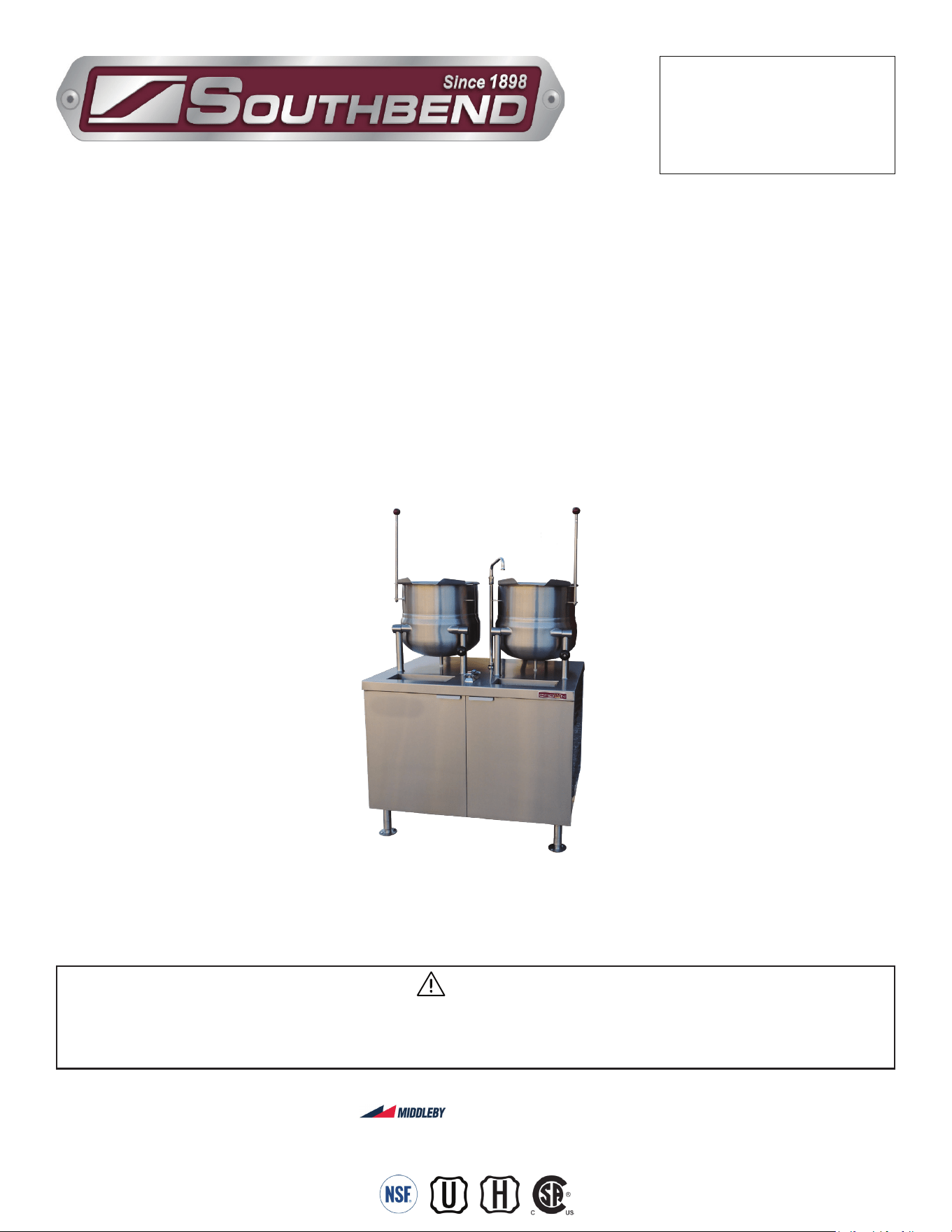
Direct Steam Kettles Mounted on
Electric Boiler Cabinet Base
MANUAL SECTION CO
IMPORTANT FOR FUTURE REFERENCE
Please complete this information and retain this
manual for the life of the equipment:
Model #:
___________________________
Serial #:
___________________________
Date Purchased:
_____________________
WARNING
Improper installation, adjustment, alteration, service or maintenance can cause property damage, injury
or death. Read the installation, operating and maintenance instructions thoroughly before installing or
servicing this equipment.
Installation & Operation Manual
Model EMT-10S-10
Direct Steam Kettles
Mounted on Electric Boiler Cabinet Base
KEMT-6, KEMT-10, KEMT-12,
EMT-6S-6, EMT-10S-6 & EMT-10S-10
SOUTHBEND STEAM
A Middleby Company
1100 Old Honeycutt Road Fuquay-Varina, North Carolina 27526 USA
www.southbendnc.com
PAGE
2
OF 20
INSTALLATION & OPERATION MANUAL 10071-SB REV 0 (07/22)
Direct Steam Kettles Mounted on Electric Boiler Cabinet Base
SAFETY PRECAUTIONS
Before installing and operating this equipment, be sure everyone involved in its operation is fully trained and aware of
precautions. Accidents and problems can be caused by failure to follow fundamental rules and precautions.
The following symbols, found throughout this manual, alert you to potentially dangerous conditions to the operator,
service personnel, or to the equipment.
CAUTION
WARNING
NOTICE
This symbol warns of immediate hazards that will result in severe injury or death.
This symbol refers to a potential hazard or unsafe practice that could result in injury or death.
This symbol refers to a potential hazard or unsafe practice that could result in injury, product
damage, or property damage.
This symbol refers to information that needs special attention or must be fully
understood, even though not dangerous.
DANGER
S
PECIFICATIONS
WARNING
Improper installation, operation, adjustment, alteration, service or maintenance can cause property damage, injury
or death. Read the installation, operating and maintenance instructions thoroughly before installing, operating or
servicing this equipment.
NOTICE
This manual should be retained for future reference.
NOTICE
This product is intended for commercial use only. NOT FOR HOUSEHOLD USE.
Copyright © 2022 by Southbend Steam. All rights reserved. Published in the United States of America.
IMPORTANT NOTES FOR INSTALLATION AND OPERATION
WARNING
This is the safety alert symbol. It is used to alert you to potential personal injury hazards. Obey all safety messages
that follow this symbol to avoid possible injury or death.
WARNING
FOR YOUR SAFETY:
Do not store or use gasoline or other ammable vapors or liquids in the vicinity of this or any other appliance.
WARNING
Disconnect the power supply to the appliance before cleaning or servicing.
CAUTION
Operating, testing, and servicing should only be performed by qualied personnel.

PAGE
3
OF 20
INSTALLATION & OPERATION MANUAL 10071-SB REV 0 (07/22)
Direct Steam Kettles Mounted on Electric Boiler Cabinet Base
RETAIN THIS MANUAL FOR FUTURE REFERENCE.
Table of Contents
Important Notes For Installation and Operation .................................................................... 2
Service Connections ............................................................................................................. 4
Introduction ........................................................................................................................... 8
Installation Instructions ......................................................................................................... 9
Operation .............................................................................................................................. 11
Operation Instructions for Boilers with CSD-1 Controls ................................................... 12
Periodic Maintenance ........................................................................................................... 13
Cleaning ................................................................................................................................ 14
Adjustments .......................................................................................................................... 15
Troubleshooting .................................................................................................................... 17
Table of Contents

PAGE
4
OF 20
INSTALLATION & OPERATION MANUAL 10071-SB REV 0 (07/22)
Direct Steam Kettles Mounted on Electric Boiler Cabinet Base
Service Connections
SERVICE CONNECTIONS
DISCLAIMER
WATER QUALITY STATEMENT
Water is the essential ingredient in steam equipment, water quality is the major factor aecting the performance of your appliance. Crown Steam Group oers a
Comprehensive Water Treatment System which exceeds our minimum water requirements. Proof of installation and proper cartridges replacement is required for
warranty coverage. Water supply to Crown Steam Group steamers must be within these guidelines.
Total dissolved solids.......................Less than 60 PPM Chlorine ............................Less than 1.5 PPM
Total alkalinity ........................................ Less than 20 PPM pH Factor .........................6.8 - 7.3
Silica ....................................................... Less than 13 PPM
Water which does not meet these standards should be treated with the installation of Middleby’s Water Treatment System. Call 919-762-1000 if you have questions
concerning your water meeting these parameters.
*Failure or malfunction of this appliance due to poor water quality is not covered under warranty.
Reference www.crownsteamgroup.com for complete warranty details and instructions.
ELECTRICAL CHARACTERISTICS
Service Connections
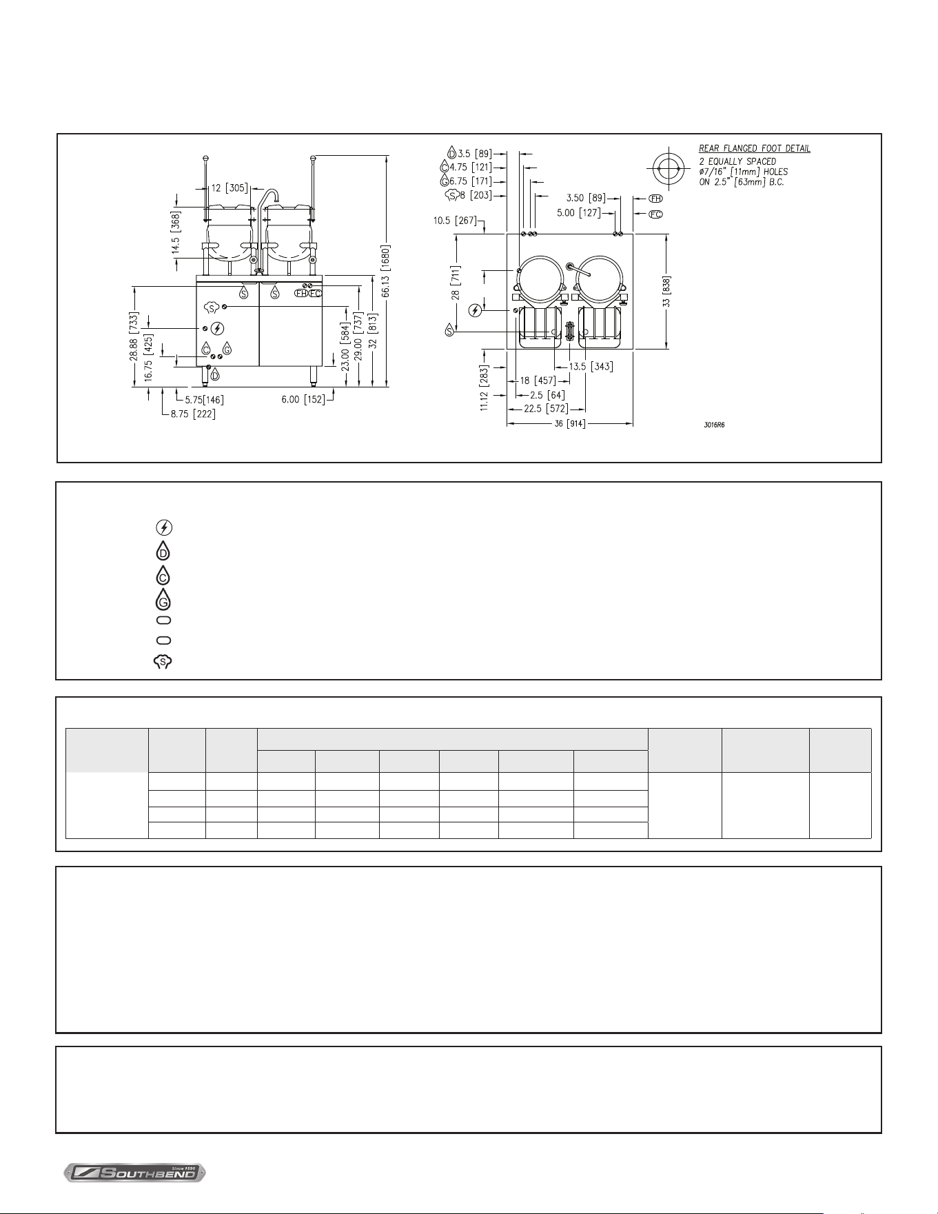
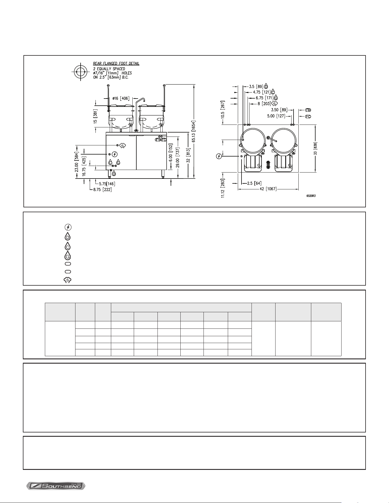
DIMENSIONS AND SPECIFICATIONS
– FIELD WIRE ELECTRICAL CONNECTION: Field wiring electrical connection to be as specied on data plate.
– SINK DRAIN: 2” (51 mm) IPS piped to open oor drain. No Solid Connection.
– CONDENSATE COLD WATER: 1/2” (13 mm) NPT at 25-50 PSI (170-345 kPa). (OPTIONAL)
– BOILER FEED WATER: 1/2” (13 mm) NPT at 25-50 PSI (170-345 kPa).
FC
– FAUCET COLD WATER: 3/8” (10 mm) O.D. tubing at 25-50 PSI (170-345 kPa), NSF-61 compliant.
FH
– FAUCET HOT WATER: 3/8” (10 mm) O.D. tubing at 25-50 PSI (170-345 kPa), NSF-61 compliant.
– STEAM TAKE-OFF CONNECTION: 3/4” (19 mm) IPS optional to operate adjacent equipment.
NOTE: SPLASH GUARD NOT SHOWN IN FRONT VIEW.
Model Capacity a b c d e f g h j k l m Shipping Weight Min. Clearance
KEMT-6 6 gal. (23 L) 12 (305) 14.5 (368) 66.13 (1680)
3.5
(89)
10.5
(267)
8.75
(222)
5.5
(140)
7
(178)
2.5
(64)
11.12
(283)
9
(229)
12
(305)
450 lbs. [204 kg.]
SIDES 0 [0 mm]
BACK 0 [0 mm]
KEMT-10 10 gal. (38 L) 16 (406) 15 (381) 65.13 (1654) 470 lbs. [213 kg.]
KEMT-12 12 gal. (45 L) 16 (406) 17 (432) 67.13 (1705) 479 lbs. [217 kg.]
Model Phase kW
Amps Per Line
208V 220V 240V 380V 415V 480V
KEMT-6
KEMT-10
KEMT-12
3 24 66.6 63 57.7 36.5 33.4 28.9
3 36 99.9 94.5 86.6 54.7 50.1 43.3
3 42 116.6 110.2 101 63.8 58.4 50.5
3 48 N/A N/A 115.5 72.9 66.8 57.7
Terry System Cartridge Changes / Installation – “2-3 gallons of water MUST be purged at each cartridge change or new installation prior to
water supply being fed to the steamer. Failure to do so can result in component damage within the steamer which is not covered under warranty.
For additional guidance on proper installation, refer to install documentation provided with each Terry System and Replacement Cartridge Set.”
As continued product improvement is a policy of Southbend Steam, specications are subject to change without notice.
PAGE
5
OF 20
INSTALLATION & OPERATION MANUAL 10071-SB REV 0 (07/22)
Direct Steam Kettles Mounted on Electric Boiler Cabinet Base
SERVICE CONNECTIONS
DISCLAIMER
WATER QUALITY STATEMENT
Water is the essential ingredient in steam equipment, water quality is the major factor aecting the performance of your appliance. Crown Steam Group oers a
Comprehensive Water Treatment System which exceeds our minimum water requirements. Proof of installation and proper cartridges replacement is required for
warranty coverage. Water supply to Crown Steam Group steamers must be within these guidelines.
Total dissolved solids.......................Less than 60 PPM Chlorine ............................Less than 1.5 PPM
Total alkalinity ........................................ Less than 20 PPM pH Factor .........................6.8 - 7.3
Silica ....................................................... Less than 13 PPM
Water which does not meet these standards should be treated with the installation of Middleby’s Water Treatment System. Call 919-762-1000 if you have questions
concerning your water meeting these parameters.
*Failure or malfunction of this appliance due to poor water quality is not covered under warranty.
Reference www.crownsteamgroup.com for complete warranty details and instructions.
NOTE: SPLASH GUARD NOT SHOWN IN FRONT VIEW.
IN [MM]
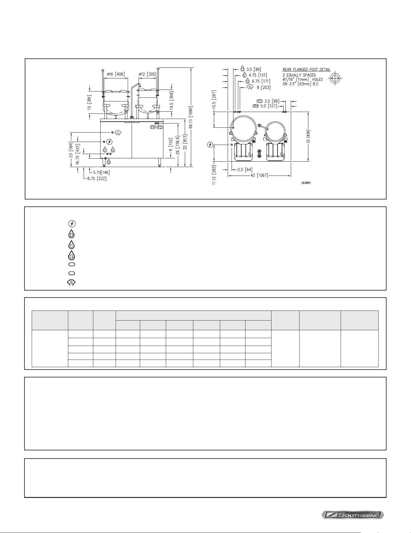
Service Connections
ELECTRICAL CHARACTERISTICS AND SPECIFICATIONS
Model Phase kW
Amps Per Line
Shipping Wt Min Clearance Capacity
208V 220V 240V 380V 415V 480V
EMT-6S-6
3 24 66.6 63 57.7 36.5 33.4 28.9
600 lbs.
[272 kg.]
SIDES 0 [0 mm]
BACK 0 [0 mm]
(2) 6 gallon
(23 litre)
3 36 99.9 94.5 86.6 54.7 50.1 43.3
3 42 116.6 110.2 101 63.8 58.4 50.5
3 48 N/A N/A 115.5 72.9 66.8 57.7
– FIELD WIRE ELECTRICAL CONNECTION: Field wiring electrical connection to be as specied on data plate.
– SINK DRAIN: 2” (51 mm) IPS piped to open oor drain. No Solid Connection.
– CONDENSATE COLD WATER: 1/2” (13 mm) NPT at 25-50 PSI (170-345 kPa). (OPTIONAL)
– BOILER FEED WATER: 1/2” (13 mm) NPT at 25-50 PSI (170-345 kPa).
FC
– FAUCET COLD WATER: 3/8” (10 mm) O.D. tubing at 25-50 PSI (170-345 kPa), NSF-61 compliant.
FH
– FAUCET HOT WATER: 3/8” (10 mm) O.D. tubing at 25-50 PSI (170-345 kPa), NSF-61 compliant.
– STEAM TAKE-OFF CONNECTION: 3/4” (19 mm) IPS optional to operate adjacent equipment.
Terry System Cartridge Changes / Installation – “2-3 gallons of water MUST be purged at each cartridge change or new installation prior to
water supply being fed to the steamer. Failure to do so can result in component damage within the steamer which is not covered under warranty.
For additional guidance on proper installation, refer to install documentation provided with each Terry System and Replacement Cartridge Set.”
As continued product improvement is a policy of Southbend Steam, specications are subject to change without notice.
PAGE
6
OF 20
INSTALLATION & OPERATION MANUAL 10071-SB REV 0 (07/22)
Direct Steam Kettles Mounted on Electric Boiler Cabinet Base
SERVICE CONNECTIONS
DISCLAIMER
WATER QUALITY STATEMENT
Water is the essential ingredient in steam equipment, water quality is the major factor aecting the performance of your appliance. Crown Steam Group oers a
Comprehensive Water Treatment System which exceeds our minimum water requirements. Proof of installation and proper cartridges replacement is required for
warranty coverage. Water supply to Crown Steam Group steamers must be within these guidelines.
Total dissolved solids.......................Less than 60 PPM Chlorine ............................Less than 1.5 PPM
Total alkalinity ........................................ Less than 20 PPM pH Factor .........................6.8 - 7.3
Silica ....................................................... Less than 13 PPM
Water which does not meet these standards should be treated with the installation of Middleby’s Water Treatment System. Call 919-762-1000 if you have questions
concerning your water meeting these parameters.
*Failure or malfunction of this appliance due to poor water quality is not covered under warranty.
Reference www.crownsteamgroup.com for complete warranty details and instructions.
ELECTRICAL CHARACTERISTICS AND SPECIFICATIONS
NOTE: SPLASH GUARD NOT SHOWN IN FRONT VIEW.
IN [MM]
Service Connections
– FIELD WIRE ELECTRICAL CONNECTION: Field wiring electrical connection to be as specied on data plate.
– SINK DRAIN: 2” (51 mm) IPS piped to open oor drain. No Solid Connection.
– CONDENSATE COLD WATER: 1/2” (13 mm) NPT at 25-50 PSI (170-345 kPa). (OPTIONAL)
– BOILER FEED WATER: 1/2” (13 mm) NPT at 25-50 PSI (170-345 kPa).
FC
– FAUCET COLD WATER: 3/8” (10 mm) O.D. tubing at 25-50 PSI (170-345 kPa), NSF-61 compliant.
FH
– FAUCET HOT WATER: 3/8” (10 mm) O.D. tubing at 25-50 PSI (170-345 kPa), NSF-61 compliant.
– STEAM TAKE-OFF CONNECTION: 3/4” (19 mm) IPS optional to operate adjacent equipment.
Terry System Cartridge Changes / Installation – “2-3 gallons of water MUST be purged at each cartridge change or new installation prior to
water supply being fed to the steamer. Failure to do so can result in component damage within the steamer which is not covered under warranty.
For additional guidance on proper installation, refer to install documentation provided with each Terry System and Replacement Cartridge Set.”
Model Phase kW
Amps Per Line
Shipping
Weight
Minimum Clear-
ance
Capacity
208V 220V 240V 380V 415V 480V
EMT-10S-6
1 24 115.4 109.1 100 N/A N/A N/A
700 lbs.
[317 kg.]
SIDES 0 [0 mm]
BACK 0 [0 mm]
(1) 10 gallon
(38 litre) and
(1) 6 gallon
(23 litre)
3 24 66.6 63 57.7 36.5 33.4 28.9
3 36 99.9 94.5 86.6 54.7 50.1 43.3
3 42 116.6 110.2 101 63.8 58.4 50.5
3 48 133.2 126 115.5 72.9 66.8 57.7
As continued product improvement is a policy of Southbend Steam, specications are subject to change without notice.
PAGE
7
OF 20
INSTALLATION & OPERATION MANUAL 10071-SB REV 0 (07/22)
Direct Steam Kettles Mounted on Electric Boiler Cabinet Base
SERVICE CONNECTIONS
DISCLAIMER
WATER QUALITY STATEMENT
Water is the essential ingredient in steam equipment, water quality is the major factor aecting the performance of your appliance. Crown Steam Group oers a
Comprehensive Water Treatment System which exceeds our minimum water requirements. Proof of installation and proper cartridges replacement is required for
warranty coverage. Water supply to Crown Steam Group steamers must be within these guidelines.
Total dissolved solids.......................Less than 60 PPM Chlorine ............................Less than 1.5 PPM
Total alkalinity ........................................ Less than 20 PPM pH Factor .........................6.8 - 7.3
Silica ....................................................... Less than 13 PPM
Water which does not meet these standards should be treated with the installation of Middleby’s Water Treatment System. Call 919-762-1000 if you have questions
concerning your water meeting these parameters.
*Failure or malfunction of this appliance due to poor water quality is not covered under warranty.
Reference www.crownsteamgroup.com for complete warranty details and instructions.
NOTE: SPLASH GUARD NOT SHOWN IN FRONT VIEW.
IN [MM]
Service Connections
ELECTRICAL CHARACTERISTICS AND SPECIFICATIONS
Model Phase kW
Amps Per Line
Shipping
Weight
Minimum
Clearance
Capacity
208V 220V 240V 380V 415V 480V
EMT-10S-10
1 24 115.4 109.1 100 N/A N/A N/A
720 lbs.
[327 kg.]
SIDES 0 [0 mm]
BACK 0 [0 mm]
(2) 10 gallon
(38 litre)
3 24 66.6 63 57.7 36.5 33.4 28.9
3 36 99.9 94.5 86.6 54.7 50.1 43.3
3 42 116.6 110.2 101 63.8 58.4 50.5
3 48 N/A N/A 115.5 72.9 66.8 57.7
– FIELD WIRE ELECTRICAL CONNECTION: Field wiring electrical connection to be as specied on data plate.
– SINK DRAIN: 2” (51 mm) IPS piped to open oor drain. No Solid Connection.
– CONDENSATE COLD WATER: 1/2” (13 mm) NPT at 25-50 PSI (170-345 kPa). (OPTIONAL)
– BOILER FEED WATER: 1/2” (13 mm) NPT at 25-50 PSI (170-345 kPa).
FC
– FAUCET COLD WATER: 3/8” (10 mm) O.D. tubing at 25-50 PSI (170-345 kPa), NSF-61 compliant.
FH
– FAUCET HOT WATER: 3/8” (10 mm) O.D. tubing at 25-50 PSI (170-345 kPa), NSF-61 compliant.
– STEAM TAKE-OFF CONNECTION: 3/4” (19 mm) IPS optional to operate adjacent equipment.
Terry System Cartridge Changes / Installation – “2-3 gallons of water MUST be purged at each cartridge change or new installation prior to
water supply being fed to the steamer. Failure to do so can result in component damage within the steamer which is not covered under warranty.
For additional guidance on proper installation, refer to install documentation provided with each Terry System and Replacement Cartridge Set.”
As continued product improvement is a policy of Southbend Steam, specications are subject to change without notice.

PAGE
8
OF 20
INSTALLATION & OPERATION MANUAL 10071-SB REV 0 (07/22)
Direct Steam Kettles Mounted on Electric Boiler Cabinet Base
General
Direct steam tilting kettle(s) mounted on a cabinet base, housing an ASME Code designed electric steam boiler approved
as a steam boiler restricted to operation at pressure not to exceed 15 psi. Hot and cold water ll faucet, 5” (152 mm) deep
sink with drain and splash guard(s). All models are suxed with either -6, -10 or -12 to indicate the capacity of the kettle(s)
in US gallons. The electric boiler may be rated at 24 kW, 36 kW, 42 kW or 48 kW. Operational on 208V, 220V, 240V, 380V,
415V or 480V and have optional CSD1 controls.
Functioning Mode
Direct connected steam jacketed kettles consist of a stainless steel bowl and a stainless steel jacket which envelopes two
thirds of the lower surface of the bowl thus forming a sealed pressure vessel (chamber) into which steam is introduced by
means of a manual control valve.
The kettle bowl is the container for the food product which ideally should be of a liquid or semi-liquid consistency to
achieve complete contact with the bowl surface and thus fully absorb the heat transmitted through that surface.
The temperatures required for the cooking process to function adequately must be greater than the boiling point of the
liquid food product. Further, the greater the steam pressure used, the higher the temperature and consequently the
quicker the cooking process. For example, steam pressurized at 30 p.s.i. attains a temperature of 274 degrees Fahrenheit
(135 degrees Celsius).
In the initial stages of the cooking process when the steam comes in contact with the cold kettle bowl surface it condenses
and forms considerable amounts of water. A thermostatic steam trap has been plumbed to the exit end of the kettle jacket.
This trap is a mechanical device that closes on high temperatures and opens when the temperature drops thus allowing
the water formed from condensate to exhaust but retain steam under pressure.
Introduction - Direct Steam Kettles
Introduction

PAGE
9
OF 20
INSTALLATION & OPERATION MANUAL 10071-SB REV 0 (07/22)
Direct Steam Kettles Mounted on Electric Boiler Cabinet Base
Unpacking
IMMEDIATELY INSPECT FOR SHIPPING DAMAGE
Immediately after unpacking, check for possible shipping damage. If the appliance is found to be damaged, save the
packaging material and contact the carrier within 15 days of delivery.
We cannot assume responsibility for damage or loss incurred in transit.
Before installing, verify that the gas (natural or propane), the elevation from sea level and the electrical supply agree
with the specication on the data plate. NOTE: If this appliance is being installed above 2000 feet altitude, contact your
authorized service oce to assure that the proper orice size for your elevation has been installed.
Installation Instructions
Location
Position the boiler in its installation location. Check that there are sucient clearances to service the controls, door
swing, etc. Also adequate clearance must be left for making the required supply and drain connections.
Allow enough space between any other piece of equipment or wall for service access.
Service to the controls may be required on the left and/or right side panels of the cabinet.
Installation Codes and Standards
The boiler must be installed in accordance with:
In Canada:
Provincial and local codes, or in the absence of local codes, with the Canadian Electric Code, CSA C22.1 (latest edition).
Copies may be obtained from the Canadian Standards Association, 178 Rexdale Blvd., Toronto, Ontario, Canada, M9W 1R3.
In the U.S.A.:
State and local codes, or in the absence of local codes, with the National Electrical Code, ANSI/NFPA-70 (latest edition).
Copies may be obtained from The National Fire Protection Association, Batterymarch Park, Quincy, MA, U.S.A., 02269.
Levelling and Anchoring the Cabinet
1. Place appliance in the installation position.
2. Place a carpenter’s level on top of the appliance and turn the adjustable feet to level side-to-side and front-to-back.
3. Mark hole locations on the oor through the anchoring holes provided in the rear anged adjustable feet.
4. Remove appliance from installation position and drill holes in locations marked on the oor. (See Installation Diagram
on page 4.) Insert proper anchoring devices (not supplied).
5. Place appliance back in the installation position.
6. Place carpenter’s level on top appliance and re-level side-to-side and front-to-back.
7. Bolt and anchor appliance securely to the oor.
8. Seal bolts and anged feet with silastic or equivalent compound.
Installation
PAGE
10
OF 20
INSTALLATION & OPERATION MANUAL 10071-SB REV 0 (07/22)
Direct Steam Kettles Mounted on Electric Boiler Cabinet BaseInstallation
Electrical Connections
WARNING
Plumbing connections must comply with applicable sanitary, safety, and plumbing codes.
WARNING
Electrical and grounding connections must comply with the applicable portions of the National Electrical
Code and/or other local codes.
WARNING
Do not connect the appliance to the electrical supply until after the gas connection has been made.
When making electrical connections, use copper wire suitable for at least 200 °F (90 °C). The steamer must be grounded
in accordance with the National Electrical Code or applicable local codes.
The wiring diagram is located on the inside of the right panel.
Exhaust Hood
An exhaust system should be located directly above the boiler to exhaust steam and heat generated by the boiler.
Plumbing Connections (See Page 4)
Water Supply Connection
The incoming cold water supply connection, at the rear of the boiler cabinet, requires 3/8” tubing and water pressure
of 25 - 50 psig. A manual shut-o valve must be provided convenient to the boiler; this valve should be open when
the boiler is in operation.
Drain Connection
The boiler drain (2” IPS) should be piped to a oor drain near the boiler. There should be no solid drain connection; an
“open gap” between the boiler and the oor drain is required.
PAGE
11
OF 20
INSTALLATION & OPERATION MANUAL 10071-SB REV 0 (07/22)
Direct Steam Kettles Mounted on Electric Boiler Cabinet Base
OPERATION
For CSD-1 equipped boilers, see this section for Operation Instructions for CSD-1 Equipped Boilers.
Boiler Controls (Inside Cabinet)
Main Power Switch - ON lls the boiler tank and turns the boiler controls on. You should allow 20 minutes to ll
the tank and generate steam.
- OFF shuts o the boiler heaters and opens the Automatic Blowdown Valve, emptying
the boiler tank and releasing water and steam to the drain. This should be done daily to
remove sediment, lime, or scale.
Pilot Light - Indicates main power is ON.
Boiler Pressure Gauge - Should read 9 -11 psi during operation; 0 psi during shutdown.
Water Level Sight Glass - Observe level of water and water quality in the boiler. Murkiness in the water indicates
inadequate water quality; the owner must supply proper water to the boiler (see Service
Connections Water Quality Statement).
Water Level Control - While boiler is ON, briey open the water level control valve once a day to remove any sediment
that might accumulate. (see Periodic Maintenance Section).
Safety Valve - This valve will release (pop o) if the boiler has too much pressure. Once a week, this
valve should be tripped during operation to make sure it functions properly.
Operating Instructions
Operation
Operation of the Boiler
Turn on water and power supply.
Open cabinet door and turn main power switch ON. Pilot light ignites and water begins to ll boiler - observe water gauge
sight glass to verify that proper water level is reached.
Once the proper water level is reached, the heaters begin to heat the water. Heaters require about 15 minutes to begin
steam generation. The boiler pressure gauge in the cabinet should indicate steam pressure in a range of 9 to 11 psig.
Operating Procedures
CAUTION
The appliance and its parts are hot. Use care when operating, cleaning and servicing the appliance.
With Boiler In Operation Mode
1. Fill kettle with product to desired level.
2. Slowly turn the steam control valve to full open position.
3. The water or food should boil 3 - 4 minutes per gallon. If it does not, then incoming pressure should be checked to
determine that it is adequate to operate the kettle eciently.
4. Regulate steam control valve depending on type of food being prepared.
5. When food is cooked, turn o steam, remove food and clean kettle immediately to prevent residue from drying on
kettle bowl surface.
Shut Down
Turn the Main Power Switch OFF. Open manual drain valve. If unit is supplied with Automatic Blowdown Valve, it will
open, draining the boiler and releasing hot water and steam to the drain.

PAGE
12
OF 20
INSTALLATION & OPERATION MANUAL 10071-SB REV 0 (07/22)
Direct Steam Kettles Mounted on Electric Boiler Cabinet BaseOperation
CSD-1 Optional Feature
Start-up Procedure
1. Close the manual blowdown valve.
2. Open cabinet door and turn “ON” power switch.
The green pilot light will come “ON.” Water will begin to enter the boiler. When enough water has entered the boiler,
the (amber) “STANDBY” pilot light will come on.
3. Press the “RESET” switch to begin boiler operation.
The “STANDBY” pilot light will go o and the boiler will begin operation.
Normal Boiler Operating Cycle
Water Fill Cycle
On the initial lling of the boiler, the reset switch must be activated to initialize the safety lockout circuit. Once the water in
the boiler has reached the proper level, the level control will stop the ow of water to the boiler. As water is consumed in
the production of steam, the level control will supply additional water to the boiler.
Firing Cycle
The elements are operated by pressure sensing devices. On initial operation, the boiler should reach 11 psi in
approximately 15 minutes. At this point, the operating pressure switch will open, de-energizing the elements. Thereafter
the operating pressure switch will cycle the elements between 9 and 11 psi boiler pressure.
Condensing Drain
A thermostat is located in the drain assembly and is activated by the temperature of steam. The thermostat operates the
cooling solenoid, supplying water to the drain to condense the steam.
Automatic Blowdown Valve
If the unit has an automatic blowdown valve, it is activated when the main power switch is activated. The boiler will be
drained should the main power switch be turned “OFF.”
Safety Lockout Conditions
High Temperature Condition
A high temperature safety device is installed on the boiler. Should the temperature exceed the limit of this device, the
boiler will be shut down and put in a state of lockout. The “TEMPERATURE” pilot light (red), and the “STANDBY” pilot light
(amber), will come on.
High Pressure Condition
A high pressure safety switch is installed on the boiler. Should the pressure exceed the limit of this device, the boiler will
be shut down and put into a state of lockout. The “PRESSURE” pilot light (red), and the “STANDBY” pilot light (amber),
will come on. Should this device fail to operate, the safety relief valve will open.
Low Water Condition
A second low water safety cut o is supplied with the boiler. Should the water level fall below normal operating levels, the
boiler will be shut down and put into a state of lockout. The “LOW WATER” pilot light (red), and the “STANDBY” pilot light
(amber) will come on.
PAGE
13
OF 20
INSTALLATION & OPERATION MANUAL 10071-SB REV 0 (07/22)
Direct Steam Kettles Mounted on Electric Boiler Cabinet Base Periodic Maintenance
PERIODIC MAINTENANCE
WARNING
Disconnect the unit from the power supply before cleaning or servicing appliance.
IMPORTANT INSTRUCTIONS
Be sure to ush your boiler water level control daily. Failure to follow this procedure can cause the control to malfunction
resulting in serious boiler damage.
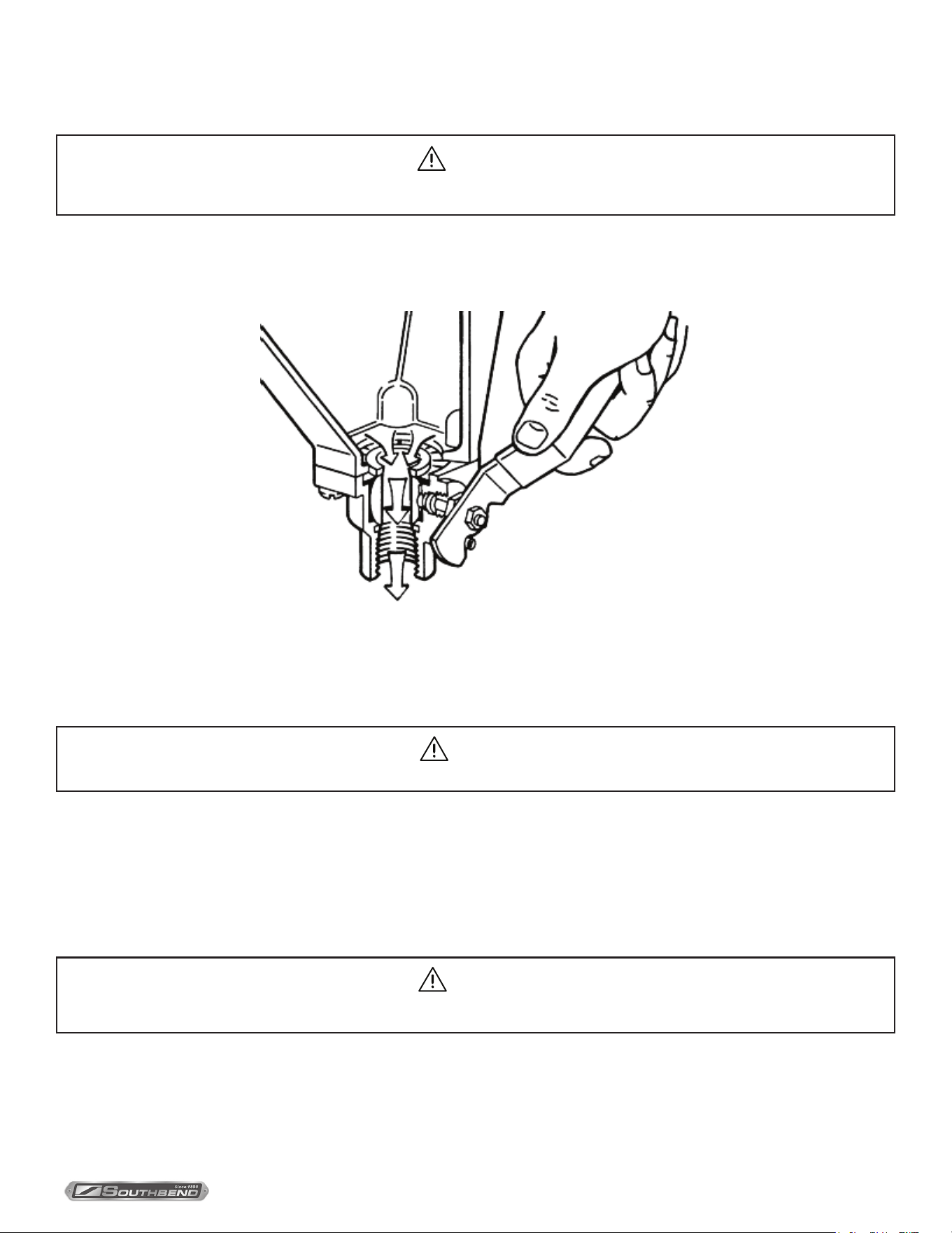
The Boiler Water Level Control installed on your boiler requires periodic maintenance. As boiler water circulates into
the oat chamber, sand, scale and other sediment may be deposited in the oat chamber. While the chamber has been
designed with a large accumulation bowl, it is necessary to ush the sediment from the chamber by blowing down the
control so that the accumulation of sediment does not interfere with the movement of the oat in the control.
Control must be ushed at least once a day.
CAUTION
Protect yourself. When ushing control, hot water and steam will ow out of the drain.
When ushing control, note water level in gauge glass, allow the boiler to ll if necessary and also to come up to temperature.
Before ushing control, note that water level in gauge glass is within operating range and the boiler pressure is at least
6 psi. While the boiler is being red, open blowdown valve at bottom of control by rotating the handle counterclockwise
about 1/4 turn to fully open the valve
Opening the blowdown valve also checks the cut-o operation. Float should drop shutting burners o, hot water and
steam will ow out the drain ushing away sediment.
CAUTION
If heater does not shut o during blowdown, immediately discontinue use of appliance and call for service.
Continue draining water for about fteen (15) seconds, from control until water is clean. Manually close valve. Recheck gauge
glass. If water level has dropped signicantly, wait for the boiler to restore water level and pressure and repeat if necessary.
1. Observe that the water in gauge glass is clean and clear. Extreme murkiness in water indicates inadequate water quality.
2. Safety valve should be tripped during operation once a week to assure that it functions properly.
3. Keep all exposed cleanable areas of unit clean at all times.
PAGE
14
OF 20
INSTALLATION & OPERATION MANUAL 10071-SB REV 0 (07/22)
Direct Steam Kettles Mounted on Electric Boiler Cabinet BaseCleaning
Cleaning
CAUTION
Do not use cleaning agents that are corrosive.
Your kettle should be cleaned immediately after each use.
1. Ensure that steam supply is OFF.
2. Pre-rinse inside of kettle thoroughly and tilt to remove any food particles.
3. Using a nylon brush, clean kettle with a mild detergent and warm water rinse. Never use steel wool or scouring
powder as it will scratch stainless steel.
4. Tilt kettle and rinse thoroughly draining out detergent solution.
Use of cleaning agents that contain chloride, acids or salts are corrosive and may cause pitting and corrosion when used
over a period of time; this will reduce the life of the appliances.
Should pitting or corrosion occur this is not covered by warranty.
Follow the recommended cleaning instructions. Use a mild detergent, warm water and rinse thoroughly.
What to Do if Surface Rust Appears
Metal utensils should never be used as they will scratch the surface of the equipment and rust may begin to form. To
remove surface accumulation of rust from the inadvertent use of such utensils, the following procedure may be used.
WARNING
Disconnect the unit from the power supply before cleaning or servicing appliance.
1. Use undiluted white vinegar with a non-abrasive scouring pad (plastic) or cloth on the aected area to remove the rust
stain. The appliance should not be heated and remain at room temperature during the entire cleaning process.
2. If the stain resists removal, additional exposure time with vinegar may be required, to a maximum of one hour.
3. Thoroughly wash all of the vinegar away with fresh clear water. Dry the surface completely and allow one hour before
using the appliance to cook.
Following daily and period maintenance procedures will prolong the life for your equipment. Climatic conditions - salt air -
may require more thorough and frequent cleaning or the life of the equipment could be adversely aected.
CAUTION
Improper use of this procedure may damage your appliance!
CAUTION
DO NOT allow water near the electrical components.
PAGE
15
OF 20
INSTALLATION & OPERATION MANUAL 10071-SB REV 0 (07/22)
Direct Steam Kettles Mounted on Electric Boiler Cabinet Base
Adjustments
Adjustments
NOTICE
Contact the factory, the factory representative or local service company to perform maintenance and repairs.
Boiler Descaling Instructions
It is recommended that the boiler be checked every 90 to 120 days for scale build up. Regular maintenance should be
carried out at this time.
1. With boiler empty, close manual blowdown valve. If appliance is equipped with Automatic Blowdown, turn water supply
to appliance OFF. Turn power switch ON. This will energize and close blowdown valve.
2. Remove 3/4” pipe plug from tting on left front of boiler.
3. Insert appropriate hose or tube through tting and pour in (1/2) half gallon (U.S.) of CLR Descaling Solution.
If available, use the Optional Deliming assembly DPA-1 available from your dealer.
4. Replace 3/4” pipe plug securely.
5. Open water supply to appliance allowing water to ll boiler to required level.
6. Let appliance cycle, allow two hours for descaling and cleaning. DO NOT TURN ON STEAM to attached appliances
or to upper compartment.
7. Open both the blowdown and low water level control valves for complete drainage. After boiler drains, close
both valves.
8. Turn appliance switch ON. When boiler is completely lled turn power switch OFF. This will rinse and drain boiler.
Appliances with manual blowdown valve must be opened to drain.
9. Complete Step 8 twice to assure boiler is completely rinsed.
10. Appliance is now ready for use.
CAUTION
Take extra caution when blowing down water level control or tripping safety valve as extreme hot water and live steam
are present.
WARNING
At least twice a year have an authorized service technician clean and adjust the unit for maximum performance.

PAGE
16
OF 20
INSTALLATION & OPERATION MANUAL 10071-SB REV 0 (07/22)
Direct Steam Kettles Mounted on Electric Boiler Cabinet BaseAdjustments
Calibrate Pressure Switches
Pressure switch range is from 1 to 15 psi.
Adjust all settings to maximum on high signal adjustment screw on pressure switches.
Adjust in the following sequence:
‒ High limit pressure switch.
‒ Operating pressure switch.
‒ Turning screw clockwise to increase, counterclockwise to decrease pressure.
‒ Use relief valve to release pressure from boiler for settling adjustments.
1. HIGH LIMIT PRESSURE SWITCHES
Allow pressure to build until unit shuts o. This should occur at 15 psi. Set the high signal to switch at 14.5 psi on the
gauge and the low signal to 13.0 psi.
2. OPERATING PRESSURE SWITCHES
Set the high signal to switch at 11 psi on the gauge and the low signal to 9 psi.
3. Release pressure in boiler to below 9 psi. Burner will come on. Once pressure has reached 11 psi, burners will shut
o. Repeat this process several times to make sure burners come on at 9 psi and shut o at 11 psi.
Once completed, pressure switches have been calibrated.
Service
NOTICE
Contact your local authorized service oce for any repairs or adjustments needed on this equipment.
NOTICE
Pressure switches are factory set. Calibration is only required if pressure switches are replaced or if adjustment is required.
Pressure switch range is from 1 to 15 psi.

PAGE
17
OF 20
INSTALLATION & OPERATION MANUAL 10071-SB REV 0 (07/22)
Direct Steam Kettles Mounted on Electric Boiler Cabinet Base
Troubleshooting
Troubleshooting
NOTICE
Contact the factory, the factory representative or local service company to perform maintenance and repairs.
Water Not Being Supplied to Boiler
1. Water supply is “OFF”.
2. Defective water ll solenoid.
3. Water level control clogged or defective, unable to operate ll valve.
4. Check drain valve is closed.
5. Supply water pressure too low.
Automatic Blowdown Valve Does Not Drain
1. Defective blowdown valve.
2. Heat exchanger build up of scalant clogging drain lines and valve.
Boiler Achieves Pressure Slower Than Normal
1. Heavy build up of lime on elements.
2. Loose element connections.
Safety Valve Blows
1. Defective safety valve.
2. Pressure too high, pressure switch requires adjustment (lower) or may be defective.

PAGE
18
OF 20
INSTALLATION & OPERATION MANUAL 10071-SB REV 0 (07/22)
Direct Steam Kettles Mounted on Electric Boiler Cabinet Base
Notes

PAGE
19
OF 20
INSTALLATION & OPERATION MANUAL 10071-SB REV 0 (07/22)
Direct Steam Kettles Mounted on Electric Boiler Cabinet Base
Notes
PAGE
20
OF 20
INSTALLATION & OPERATION MANUAL 10071-SB REV 0 (07/22)
Direct Steam Kettles Mounted on Electric Boiler Cabinet Base
KEMT-6, KEMT-10, KEMT-12,
EMT-6S-6, EMT-10S-6 & EMT-10S-10
Direct Steam Kettles
Mounted on Electric Boiler Cabinet Base
A product with the Southbend Steam name incorporates the best in durability and low maintenance. We all recognize,
however, that replacement parts and occasional professional service may be necessary to extend the useful life of this
appliance. When service is needed, contact a Southbend Steam Authorized Service Agency, or your dealer. To avoid
confusion, always refer to the model number, serial number, and type of your appliance.
SOUTHBEND STEAM
A Middleby Company
1100 Old Honeycutt Road Fuquay-Varina, North Carolina 27526 USA
www.southbendnc.com


