MANUAL 10122-SB REV 0 (11/21)
$21.00
Gas Fired Pressureless Cooker with
Direct Steam Kettles
MANUAL SECTION CO
IMPORTANT FOR FUTURE REFERENCE
Please complete this information and retain this
manual for the life of the equipment:
Model #:
___________________________
Serial #:
___________________________
Date Purchased:
_____________________
WARNING
Improper installation, adjustment, alteration, service or maintenance can cause property damage, injury
or death. Read the installation, operating and maintenance instructions thoroughly before installing or
servicing this equipment.
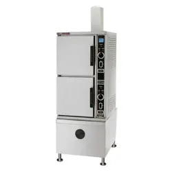
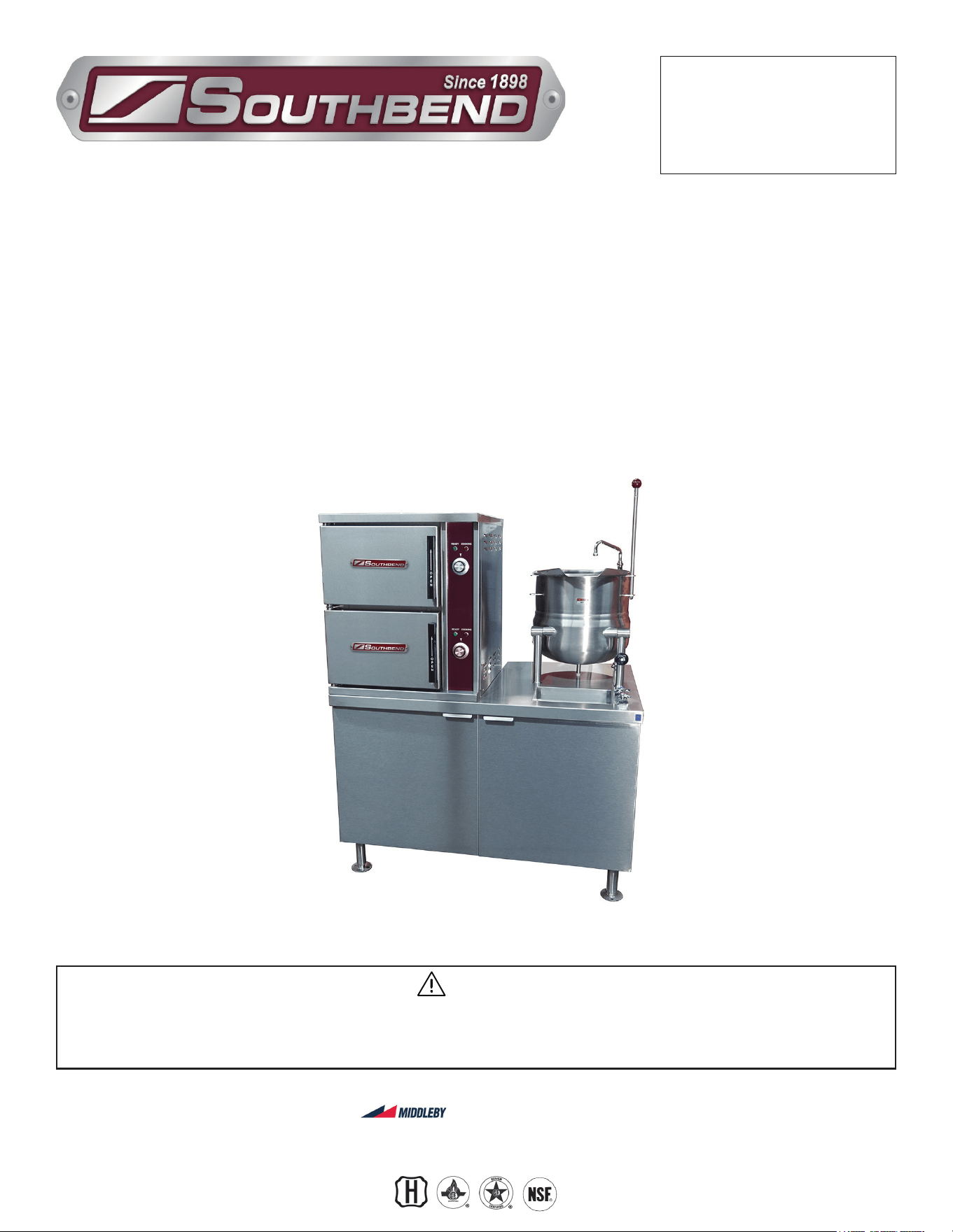
Model GCX-2S-10
Gas Fired Pressureless Cooker with
Direct Steam Kettles
GCX-2S-(6, 10), GCX-10S-(6, 10),
GCX-2S-6-(6, 10) & GCX-10S-6-(6, 10)
Installation & Operation Manual
SOUTHBEND STEAM
A Middleby Company
1100 Old Honeycutt Road Fuquay-Varina, North Carolina 27526 USA
www.southbendnc.com
INSTALLATION & OPERATION MANUAL 10122-SB REV 0 (11/21)
PAGE
2
OF 24
Gas Fired Pressureless Cooker with Direct Steam Kettles
SAFETY PRECAUTIONS
Before installing and operating this equipment, be sure everyone involved in its operation is fully trained and aware of
precautions. Accidents and problems can be caused by failure to follow fundamental rules and precautions.
The following symbols, found throughout this manual, alert you to potentially dangerous conditions to the operator,
service personnel, or to the equipment.
CAUTION
WARNING
NOTICE
This symbol warns of immediate hazards that will result in severe injury or death.
This symbol refers to a potential hazard or unsafe practice that could result in injury or death.
This symbol refers to a potential hazard or unsafe practice that could result in injury, product
damage, or property damage.
This symbol refers to information that needs special attention or must be fully
understood, even though not dangerous.
DANGER
WARNING
Improper installation, operation, adjustment, alteration, service or maintenance can cause property damage, injury or death. Read
the installation, operating and maintenance instructions thoroughly before installing, operating or servicing this equipment.
NOTICE
PURCHASER: Instructions to be followed in the event that the operator of this appliance smells gas must be posted in
a prominent location. This information shall be obtained by consulting the local gas supplier.
NOTICE
Keep the appliance area free and clear from combustibles.
Do not obstruct the ow of combustion and ventilation air.
Adequate clearances must be maintained for servicing and proper operation.
Copyright © 2021 by Southbend Steam. All rights reserved. Published in the United States of America.
Safety Precautions
IMPORTANT NOTES FOR INSTALLATION AND OPERATION
WARNING
This is the safety alert symbol. It is used to alert you to potential personal injury hazards. Obey all safety messages
that follow this symbol to avoid possible injury or death.
WARNING
FOR YOUR SAFETY:
Do not store or use gasoline or other ammable vapors or liquids in the vicinity of this or any other appliance.
NOTICE
This manual should be retained for future reference.
It is recommended that this manual be read thoroughly and that all instructions be followed carefully.
NOTICE
This product is intended for commercial use only. NOT FOR HOUSEHOLD USE.
NOTICE
Do not attempt to operate this unit in the event of a power failure.

INSTALLATION & OPERATION MANUAL 10122-SB REV 0 (11/21)
PAGE
3
OF 24
Gas Fired Pressureless Cooker with Direct Steam Kettles
RETAIN THIS MANUAL FOR FUTURE REFERENCE.
Table of Contents
Important Notes For Installation and Operation .................................................................... 2
Service Connections ............................................................................................................. 4
Introduction ........................................................................................................................... 6
Installation Instructions ......................................................................................................... 7
Operation .............................................................................................................................. 10
Operation Instructions for Boilers with CSD-1 Controls ................................................... 12
Cooker Section .................................................................................................................. 14
Functioning Mode .............................................................................................................. 15
Maintenance ......................................................................................................................... 16
Cleaning ................................................................................................................................ 18
Adjustments .......................................................................................................................... 20
Troubleshooting .................................................................................................................... 21
Table of Contents
INSTALLATION & OPERATION MANUAL 10122-SB REV 0 (11/21)
PAGE
4
OF 24
Gas Fired Pressureless Cooker with Direct Steam Kettles
SERVICE CONNECTIONS
Service Connections
GAS SUPPLY AND SPECIFICATIONS
WATER QUALITY STATEMENT
Water is the essential ingredient in steam equipment, water quality is the major factor aecting the performance of your appliance. Southbend Steam Group
oers a Comprehensive Water Treatment System which exceeds our minimum water requirements. Proof of installation and proper cartridges replacement is
required for warranty coverage. Water supply to Southbend Steam Group steamers must be within these guidelines.
Total dissolved solids..............Less than 60 PPM Chlorine ..................Less than 1.5 PPM
Total alkalinity .......................Less than 20 PPM pH Factor ..............6.8 - 7.3
Silica ......................................Less than 13 PPM
Water which does not meet these standards should be treated with the installation of Middleby’s Water Treatment System. Call 919-762-1000 if you have
questions concerning your water meeting these parameters.
*Failure or malfunction of this appliance due to poor water quality is not covered under warranty.
Reference www.crownsteamgroup.com for complete warranty details and instructions.
MISCELLANEOUS
If installing on any oor with an epoxy coating or other combustible oor surface (i.e., a surface other than quarry tile, cement or
natural stone), contact the factory for installation options as damage due to improper installation is not covered under warranty.
As continued product improvement is a policy of Southbend Steam, specications are subject to changge without notice.
BTU/Hour kW/Hour
Water Column Pressure
Natural Propane
250,000 73.3
7” - 14”
[178 mm - 355 mm]
11” - 14”
[279 mm - 355 mm]
300,000 87.9
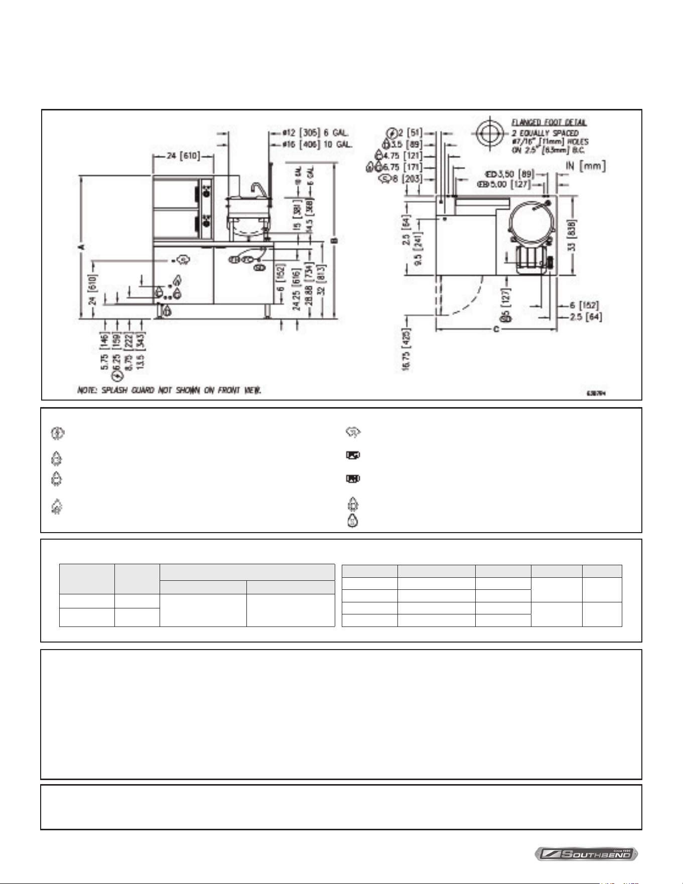
Model Shipping Weight A B C
GCX-2S-6 980 lbs. [445 kg.] 59.5 [1511]
66.13 [1680] 44 [1118]
GCX-10S-6 1000 lbs. [454 kg.] 72.5 [1842]
GCX-2S-10 1030 lbs. [467 kg.] 59.5 [1511]
65.13 [1654] 48 [1219]
GCX-10S-10 1020 lbs. [462 kg.] 72.5 [1842]
SERVICE CONNECTIONS
– ELECTRICAL CONNECTION: 1/2” (13 mm) conduit connection to controls.
120 VAC-60Hz-1PH. 2 Amps per compartment or as specied on data plate.
– BOILER COLD WATER: 3/8” (10 mm) O.D. tubing, 25-50 PSI (170-345 kPa).
– CONDENSATE COLD WATER: 3/8” (10 mm) O.D. tubing, 25-50 PSI
(170-345 kPa) (OPTIONAL)
– GAS CONNECTION: 3/4” (19 mm) IPS supply line required.
– STEAM TAKE-OFF CONNECTION: 3/4” (19 mm) IPS optional to operate
adjacent equipment.
– FAUCET COLD WATER: 3/8” (10 mm) O.D. tubing at 25-50 PSI (170-345 kPa),
NSF-61 compliant.
– FAUCET HOT WATER: 3/8” (10 mm) O.D. tubing at 25-50 PSI (170-345 kPa),
NSF-61 compliant.
– DRAIN: 2” (51 mm) IPS piped to open oor drain. No solid connection.
– SINK DRAIN: 1 1/8” (29 mm) O.D. tubing.
INSTALLATION & OPERATION MANUAL 10122-SB REV 0 (11/21)
PAGE
5
OF 24
Gas Fired Pressureless Cooker with Direct Steam Kettles
GAS SUPPLY AND SPECIFICATIONS
WATER QUALITY STATEMENT
Water is the essential ingredient in steam equipment, water quality is the major factor aecting the performance of your appliance. Southbend Steam Group
oers a Comprehensive Water Treatment System which exceeds our minimum water requirements. Proof of installation and proper cartridges replacement is
required for warranty coverage. Water supply to Southbend Steam Group steamers must be within these guidelines.
Total dissolved solids..............Less than 60 PPM Chlorine ..................Less than 1.5 PPM
Total alkalinity .......................Less than 20 PPM pH Factor ..............7.0 - 8.5
Silica ......................................Less than 13 PPM
Water which does not meet these standards should be treated with the installation of Middleby’s Water Treatment System. Call 919-762-1000 if you have
questions concerning your water meeting these parameters.
*Failure or malfunction of this appliance due to poor water quality is not covered under warranty.
Reference www.crownsteamgroup.com for complete warranty details and instructions.
MISCELLANEOUS
If installing on any oor with an epoxy coating or other combustible oor surface (i.e., a surface other than quarry tile, cement or
natural stone), contact the factory for installation options as damage due to improper installation is not covered under warranty.
As continued product improvement is a policy of Southbend Steam, specications are subject to changge without notice.
Service Connections
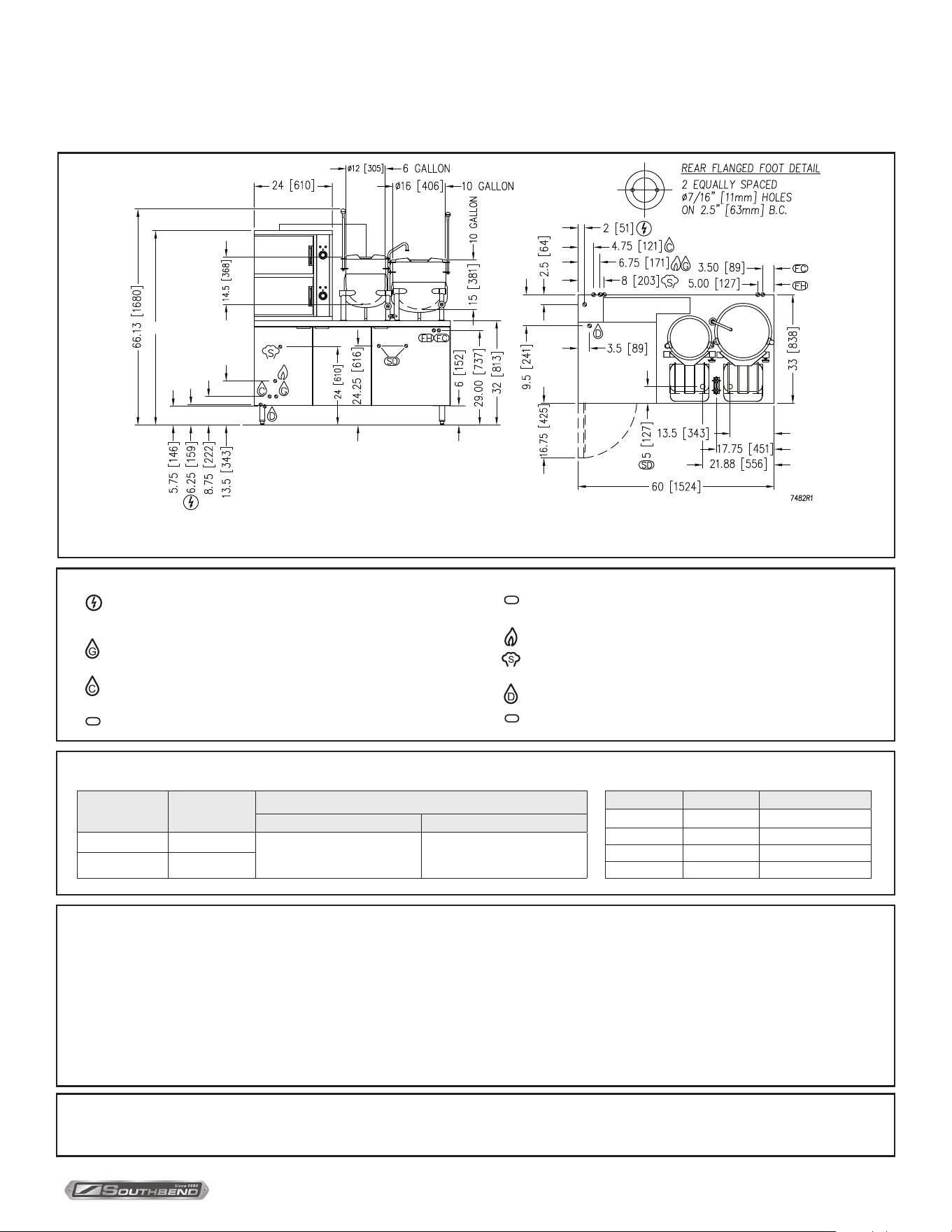
A
READY COOKING
READY COOKING
– ELECTRICAL CONNECTION: 1/2” (13 mm) conduit connection to
controls. 120 VAC-60Hz-1PH. 2 Amps per compartment or as specied on
data plate.
– BOILER FEED WATER: 1/2” (13 mm) NPT at 25-50 PSI (170-345 kPa)
.[TREATED WATER]
– CONDENSATE COLD WATER: 1/2” (13 mm) NPT at 25-50 PSI
(170-345 kPa) (OPTIONAL)
FC
– FAUCET COLD WATER: 3/8” (10 mm) O.D. tubing at 25-50 PSI
(170-345 kPa), NSF-61 compliant.
SERVICE CONNECTIONS
NOTE: SPLASH GUARD NOT SHOWN ON FRONT VIEW.
BTU/Hour kW/Hour
Water Column Pressure
Natural Propane
250,000 73.3
7” - 14”
[178 mm - 355 mm]
11” - 14”
[279 mm - 355 mm]
300,000 87.9
Model A Shipping Weight
GCX-2S-6-6 59.5 [1511] 1010 lbs. [458 kg.]
GCX-10S-6-6 72.5 [1842] 1050 lbs. [476 kg.]
GCX-2S-6-10 59.5 [1511] 1030 lbs. [467 kg.]
GCX-10S-6-10 72.5 [1842] 1070 lbs. [485 kg.]
FH
– FAUCET HOT WATER: 3/8” (10 mm) O.D. tubing at 25-50 PSI
(170-345 kPa), NSF-61 compliant.
– GAS CONNECTION: 3/4” (19 mm) IPS supply line required.
– STEAM TAKE-OFF CONNECTION: 3/4” (19 mm) IPS optional
to operate adjacent equipment.
– DRAIN: 2” (51 mm) IPS piped to open oor drain. No solid connection.
SD
– SINK DRAIN: 1-1/8” (29 mm) O.D. tubing.

INSTALLATION & OPERATION MANUAL 10122-SB REV 0 (11/21)
PAGE
6
OF 24
Gas Fired Pressureless Cooker with Direct Steam KettlesIntroduction
Description
Models GCX-2S-(6, 10), GCX-10S-(6, 10), GCX-2S-6-(6, 10), and GCX-10S-6-(6, 10) convection steamers with
direct steam kettle(s) mounted on cabinet base and a gas red boiler rated at 250,000 or 300,000 BTU. Each
steamer has a pan capacity of 6 (2-1/2”) pans. Kettle(s) is/are conveniently mounted beside the compartment cooker
complete with mounted steam control valve located in the kettle leg. Kettle(s) is/are direct connected to boiler and all
piping, steam traps and relief valves are connected to system. Kettle(s) is/are suxed with either -6 or -10 to indicate
the capacity of that kettle in U.S. gallons.
Basic Function
Gas Fired Steamers with Direct Connected Steam Kettles
The sequence of operation is as follows:
1. Turn on main power switch. Pilot light will indicate main power is on and ll solenoid will open and water will begin to
ll boiler. Allow 20 minutes to ll generator. OFF shuts o the boiler controls and opens the automatic blowdown valve,
if so equipped, emptying the boiler and releasing water and steam to the drain. Manual valve will have to be opened
to drain boiler if not equipped with automatic blowdown valve.
2. Boiler pressure gauge should read 9 - 11 psi during operation, 0 psi during shutdown.
3. Burners will cycle on and o as required to maintain pressure.
4. Compartment cooker is ready for use when READY light is on. Place pans of food to be cooked into compartments
and close door(s).
5. Set timer to cooking time desired. Cooking will commence and cooking time may be interrupted at any time by
opening door and resumed again by closing door.
6. Buzzer will sound indicating the end of the cooking cycle and that steam has stopped entering the compartment.
The COOKING pilot will go o and the READY light will come on. Buzzer must be shut o by turning the timer to
its o position.
7. Direct connected steam jacketed kettles consist of a stainless steel bowl and a stainless steel jacket which envelopes
two thirds of the lower surface of the kettle thus forming a sealed pressure vessel (chamber) into which steam is
introduced by means of a manual valve. Slowly turn steam control valve on to full open position (counterclockwise).
8. Regulate steam control valve depending on type of food being prepared.
9. To empty food from kettle, pull forward on handle slowly to avoid injury from spill and place kettle in upright position
when empty.
INTRODUCTION

INSTALLATION & OPERATION MANUAL 10122-SB REV 0 (11/21)
PAGE
7
OF 24
Gas Fired Pressureless Cooker with Direct Steam Kettles
General
The gas boiler in this appliance is designed to ASME Code and approved as a steam heating boiler restricted to operation
at pressure not to exceed 15 psi. The gas boiler is installed in a 60” cabinet base rated at 250,000 or 300,000 BTU,
operational on Natural or Propane gas. Boilers may have optional electronic ignition and CSD-1 controls.
Unpacking
IMMEDIATELY INSPECT FOR SHIPPING DAMAGE
Immediately after unpacking, check for possible shipping damage. If the appliance is found to be damaged, save the
packaging material and contact the carrier within 15 days of delivery.
We cannot assume responsibility for damage or loss incurred in transit.
Before installing, verify that the gas (natural or propane), the elevation from sea level and the electrical supply agree
with the specication on the data plate. NOTE: If this appliance is being installed above 2000 feet altitude, contact your
authorized service oce to assure that the proper orice size for your elevation has been installed.
INSTALLATION INSTRUCTIONS
Location
The installation location must be kept free and clear of combustibles. Do not obstruct the ow of combustion and
ventilation air. Clearance from combustible construction must be a minimum of 3 inches from the sides and 6 inches
from the back. The appliance should be installed on a noncombustible oor. Provide adequate clearances for cleaning,
maintenance, service and proper operation.
Sucient air should be allowed to enter the room to compensate for the amount of air removed by any ventilating system
and for combustion of the gas burners. Do not obstruct the air ow into and around the appliance. Do not obstruct the ow
of ue gases from the ue duct located at the rear and above the cabinet. Position the appliance in its nal location. Check
that there are sucient clearances to service the controls, for door swings, etc., so there will be no problem in making the
required supply and drain connections.
Allow enough space between any other piece of equipment or a wall for service access.
Service on the cabinet base may require access to the left and/or right side panels.
Installation Codes and Standards
Installation must conform to local codes, or in absence of local codes, with the National Fuel Gas Code - ANSI Z223.1/NFPA 54, or
the Natural Gas and Propane Installation Code, CSA B149.1, as applicable, including:
1. The appliance and its individual shut o valve must be disconnected from the gas supply piping system during any
pressure testing of that system at pressures in excess of 1/2 psig (3.5 kPa).
2. The appliance must be isolated from the gas supply piping system by closing its individual manual shut o valve
during any pressure testing of the gas supply piping system at test pressures equal to or less than 1/2 psig (3.5 kPa).
Electrical grounding must be provided in accordance with local codes, or in the absence of local codes, with the
National Electrical Code ANSI/NFPA 70. In Canada, installation must be in accordance with the Canadian Electrical
Code CSA C22.2.
Ventilation must be provided in accordance with local codes, or in the absence of local codes, with ANSI/NFPA 96
Standard for Ventilation and Fire Protection of Commercial Cooking Operations.
WIRING DIAGRAM FOR APPLIANCE IS LOCATED INSIDE CABINET DOOR.
Installation
INSTALLATION & OPERATION MANUAL 10122-SB REV 0 (11/21)
PAGE
8
OF 24
Gas Fired Pressureless Cooker with Direct Steam Kettles
Levelling and Anchoring the Appliance
1. Place appliance in the installation position.
2. Place a carpenter’s level on top of the appliance and turn the adjustable feet to level side-to-side and front-to-back.
3. Mark hole locations on the oor through the anchoring holes provided in the rear anged adjustable feet.
4. Remove appliance from installation position and drill holes in locations marked on the oor. Insert proper anchoring
devices (not supplied).
5. Place appliance back in the installation position.
6. Place carpenter’s level on top of appliance and re-level side-to-side and front-to-back.
7. Bolt and anchor appliance securely to the oor.
8. Seal bolts and anged feet with silastic or equivalent compound.
Exhaust Fans and Canopies
Canopies are set over ranges, ovens, kettles, etc., for ventilation purposes. It is recommended that a canopy extend 6”
past the appliance and be located 6 feet 6 inches from the oor. Filters should be installed at an angle of 45 degrees or
more with the horizontal. This position prevents dripping of grease and facilitates collecting the run-o grease in a drip
pan, usually installed with the lter. A strong exhaust fan tends to create a vacuum in the room and may interfere with
burner performance or may extinguish pilot ames. Makeup air openings approximately equal to the fan area will relieve
such vacuum. In case of unsatisfactory performance on any appliance, check with the exhaust fan in the “OFF” position.
Information on the construction and installation of ventilating hoods may be obtained from the standard for “Vapor
Removal from Cooking Equipment”, NFPA No. 96 (latest edition), available from the National Fire Protection Association,
Batterymarch Park, Quincy, MA, USA, 02269.
Connections
Plumbing Connections
Water Supply Connection
The incoming cold water supply connection, at the rear of the steamer cabinet, requires 3/8” tubing and water pressure of 25 - 50
psi. A manual shut-o valve must be provided convenient to the appliance; this valve should be open when the boiler is in operation.
FAILURE OR MALFUNCTION OF THIS APPLIANCE DUE TO POOR WATER QUALITY IS NOT COVERED UNDER
WARRANTY. SEE WATER QUALITY STATEMENT.
Drain Connection
The appliance drain (2” IPS) should be piped to a oor drain near the steamer. There should be no solid drain connection;
an “open gap” between the steamer and the oor drain is required.
NOTICE
If this equipment is being installed at over 2,000 feet altitude and was not so specied on order, contact service
department. Failure to install with proper orice sizing may void the warranty.
WARNING
Plumbing connections must comply with applicable sanitary, safety, and plumbing codes.
IMPORTANT
If your equipment was supplied with split water lines and a lter, connect the lter system to the connection
marked “BOILER FEED” only. Make a second connection to the “CONDENSER FEED” from a cold and
unltered water supply.
Installation
INSTALLATION & OPERATION MANUAL 10122-SB REV 0 (11/21)
PAGE
9
OF 24
Gas Fired Pressureless Cooker with Direct Steam Kettles Installation
Electrical Connections
Gas Connection
1. The data plate on the cabinet door of the boiler indicates the type of gas your unit is equipped to burn. DO NOT
connect to any other gas type.
Keep the appliance area free and clear from combustible substances. Do not obstruct the ow of combustion and
ventilation air.
2. A 3/4” NPT line is provided at the rear for the connection. Each boiler is equipped with an internal pressure regulator
which is set at 3.5” W.C. manifold pressure for natural gas or 10.5” W.C. for L.P. gas. Use the 1/8” pipe tap on the
burner manifold for checking pressure.
An adequate gas supply is necessary. Undersized or low pressure lines will restrict the volume of gas required for
satisfactory performance. A steady supply pressure, between 7” W.C. and 14” W.C. for natural gas and 11” W.C. and 14”
W.C. for propane gas is recommended. With all units operating simultaneously, the manifold pressure on all units should
not show any appreciable drop. Fluctuations of more than 25% on natural gas, and 10% on propane gas, will create pilot
problems and aect burner operating characteristics. Contact your gas company for correct supply line sizes.
Purge the supply line to clean out any dust, dirt, or foreign matter before connecting the line to the unit.
Codes require that a gas shut-o valve be installed in the gas line prior to the steamer. Make sure the pipes are clean and
free of obstructions, dirt, and piping compound.
CAUTION
The pipe thread compound used when installing pipes must be a type that is resistant to the action of liquied
petroleum or propane gases.
WARNING
Prior to start-up, check all joints in the gas supply line for leaks. Use soap and water solution. Do not use
an open flame.
WARNING
Do not connect the appliance to the electrical supply until after the gas connection has been made.
NOTICE
If this equipment is being installed at over 2,000 feet altitude and was not so specied on order, contact service
department. Failure to install with proper orice sizing may void the warranty.
WARNING
Electrical and grounding connections must comply with the applicable portions of the National Electrical
Code and/or other local codes.
120 VAC-60 Hz - Single Phase
Make electrical connection to terminal block provided in rear of the appliance. A separate 15 amp supply is needed for
each unit.
Refer to the electrical diagram located inside cabinet on door.
INSTALLATION & OPERATION MANUAL 10122-SB REV 0 (11/21)
PAGE
10
OF 24
Gas Fired Pressureless Cooker with Direct Steam Kettles
OPERATION
WARNING
Do not force the gas control knob. Use only your hand to turn the gas control knob. Never use any tool. If the
gas control knob will not operate by hand the gas control should be replaced by a qualied service technician.
WARNING
Do not disassemble the gas control; it contains no replaceable components. Attempted disassembly or
repair may damage the gas control.
WARNING
In the event of main burner ignition failure, a 5 minute purge period must be observed prior to re-establishing
ignition source.
For CSD-1 equipped boilers, see this section for Operation Instructions for CSD-1 Equipped Boilers.
Boiler Controls (Inside Cabinet)
Gas steam generators are available with standard boiler controls or ASME CSD-1 complaint controls. In addition to the
ON/OFF power switch and indicator pilot light with standard controls, the CSD-1 controls have in addition four more
indicator pilot lights and a “Reset” switch. Follow the appropriate instructions for each.
Main Power Switch - ON lls the boiler tank and turns the boiler controls on. You should allow 20 minutes to ll
the tank and generate steam.
- OFF shuts o the boiler controls and opens the automatic blowdown valve, emptying the
boiler tank and releasing water and steam to the drain. This should be done at least once
daily to remove sediment, lime, or scale.
Pilot Light - Indicates main power is ON.
Boiler Pressure Gauge - Should read 9 -11 psi during operation; 0 psi during shutdown.
Water Level Sight Glass - Observe level of water in the boiler and water quality. Murkiness in the water indicates
inadequate water quality; the owner must supply proper water to the boiler (see Water
Quality Statement).
Water Level Control - While ON, briey open the water level control daily to remove any sediment that might
accumulate.
Safety Valve - This valve will release (pop o) if the boiler has too much pressure. Once a week, this
valve should be tripped during operation to make sure it functions properly.
WARNING
In the event you smell gas, shut down equipment at the main shut off valve and contact the local gas
company or gas supplier for service.
Operation

INSTALLATION & OPERATION MANUAL 10122-SB REV 0 (11/21)
PAGE
11
OF 24
Gas Fired Pressureless Cooker with Direct Steam Kettles Operation
1. START-UP - BOILER OPERATION WITH STANDING PILOT IGNITION
Open manual gas shut o supply valve and if the appliance has a manual blowdown valve, close it. Open cabinet door
and turn ON power switch located on left side. Green pilot light will come on, water will begin to enter boiler and required
water level will be reached in about three minutes. Observe water gauge glass to verify.
The dial on the combination gas control valve has three positions (ON-PILOT-OFF) for manual gas control of main burners
and pilot. Turn DIAL to PILOT. Depress dial and light pilot burner located on centre main burner of boiler. Maintain dial in
depressed position for about 30 seconds and release. Observe that the pilot burner ame stays on. If at any time the ame
should become extinguished, a 5 minute period of complete shut o of gas supply is required before relighting.
Turn dial to ON and burners should ignite. Steam generation will now commence and be completed in approximately
15 minutes. Steam generation should reach approximately 11 psi as indicated on the pressure gauge on the boiler.
2. START UP - BOILER OPERATION WITH ELECTRONIC IGNITION
Open manual gas supply valve.
Open cabinet door and turn main power switch ON. Green pilot light will come on, water will begin to enter boiler and
required water level will be reached in about 3 minutes. Observe water gauge sight glass to verify.
The dial on the gas combination control valve has 2 positions (ON and OFF).
ON - [Rotated counterclockwise] permits gas to ow to the pilot and main burner.
OFF - [Rotated clockwise] prevents gas ow to pilot and main burner.
With the gas control valve, power switch and water supply all ON, water begins entering the boiler and gas ows to the
pilot: Spark will begin in 2 to 3 seconds. If the pilot fails to light in 90 seconds, the control will provide 100% lockout. If this
occurs: Wait 5 minutes, then turn power switch o for one minute before turning power switch back on.
Once the pilot is lit and the required water level has been reached, the main burners will ignite. Burner will cycle to meet
the steam pressure required. Steam pressure should reach approximately 11 psi as indicated on the pressure gauge on
the boiler.
Daily Shut Down
Turn power switch o.
Open blowdown valve if so equipped.
Complete Boiler Shut Down
If boiler is not intended to be operated for a lengthy period of time, shut o all power, gas and water supplies to the
appliance. Open blowdown valve if so equipped.
NOTICE
Units are shipped with the control in the ON position.

INSTALLATION & OPERATION MANUAL 10122-SB REV 0 (11/21)
PAGE
12
OF 24
Gas Fired Pressureless Cooker with Direct Steam Kettles
Operation Instructions for Boilers with CSD-1 Controls
INITIAL START-UP PROCEDURE
1. Open the manual gas shut-o supply valve.
2. Close the manual blowdown valve, if so equipped.
3. Light the pilot burner.
The dial on the gas combination valve has three positions (ON - OFF - PILOT) for manual gas control of main burners
and pilot burner. Turn the dial on the gas combination valve to “PILOT”, depress the dial and light the pilot burner on
the centre burner. Maintain the dial in depressed position for about 30 seconds and release. Observe the pilot ame
stays ON. Turn dial to “ON”.
If at any time the ame should become extinguished, a ve (5) minute purging is required
before relighting is attempted.
4. Open cabinet door and turn “ON” the power switch.
The green pilot light will come “ON”. Water should begin to enter the boiler. When enough water has entered the boiler
the (amber) “STANDBY” pilot light will come on.
5. Press the “RESET” switch to begin boiler operation.
The “STANDBY” pilot light will go o and the boiler will begin operation.
Initial Start-Up Procedure with Electronic Ignition
1. Open the manual gas supply valve and water supply. Turn on power supply to the unit.
2. Open cabinet door. With gas control valve, water supply and power switch ON, green pilot light will come on. Water
will begin to enter the boiler. When enough water has entered the boiler the (amber) “STANDBY” pilot light will
come on.
The dial on the gas combination control valve has two positions (ON and OFF).
ON - (Rotated counterclockwise) permits gas to ow to the pilot and main burner.
OFF - (Rotated clockwise) prevents gas ow to pilot and main burner.
3. Press the “RESET” switch to begin the boiler operation. The “STANDBY” pilot light will go o and the boiler will
begin operation.
Daily Startup Procedure
1. Close the manual blowdown valve, if so equipped.
2. Examine that the pilot burner ame is burning. If the pilot burner is out, a ve (5) minute period of complete gas supply
shut o is required before relighting.
3. Open cabinet door and turn “ON” the power switch.
The green pilot light will come “ON”. Water will begin to enter the boiler. When enough water has entered the boiler
the (amber) “STANDBY” pilot light will come on.
4. Press the “RESET” switch to begin the boiler operation. The “STANDBY” pilot light will go o and the boiler will
begin operation.
WARNING
In the event of main burner ignition failure, a 5 minute purge period must be observed prior to re-establishing
ignition source.
NOTICE
Units are shipped with the control in the ON position.
Operation

INSTALLATION & OPERATION MANUAL 10122-SB REV 0 (11/21)
PAGE
13
OF 24
Gas Fired Pressureless Cooker with Direct Steam Kettles Operation
Daily Shutdown Procedure
1. Turn “OFF” the power switch. Observe that the burners go o.
2. Open the manual blowdown valve, if so equipped. If the appliance is equipped with an automatic blowdown solenoid
valve, the boiler’s contents, water and steam will be blown out and exhausted through the appliance drain. The cold
water solenoid valve will be activated.
Complete Shutdown Procedure
If the appliance is not intended to be operational for a lengthy period, then shut it down completely.
1. Open the manual blowdown valve, if so equipped.
2. Shut o all supplies of power, gas and water to the appliance.
Normal Boiler Operating Cycle
Water Fill Cycle
On the initial lling of the boiler, the reset switch must be activated to initialize the safety lockout circuit. Once the water
in the boiler has reached the proper level, the level control will open the circuit to the ll solenoid valve, stopping the ow
of water to the boiler. As the water is consumed in the production of steam, the level control will close the circuit to the ll
solenoid and water will be supplied to the boiler.
Firing Cycle
The gas valve is operated by pressure sensing devices. On the initial operation of the boiler, steam generation should
reach 11 psi in approximately 15 minutes. At this point the “Operating Pressure” switch will open, closing the gas valve.
When pressure drops to 9 psi, the pressure switch closes, the gas valve will open and ignition should occur.
Should the pressure rise more than 14.5 psi the “Override Pressure Switch” will close the circuit to the override solenoid
valve, releasing excess steam.
Condensing Drain
A thermostat is located in the drain assembly and is activated by the temperature of steam. The thermostat opens the
cooling solenoid valve, in turn supplying water to the drain to condense steam.
Automatic Blowdown Valve
If the unit has an automatic blowdown valve, it is activated by the main power switch. The boiler will be drained should the
main power switch be turned “OFF”.
Safety Lockout Conditions
High Temperature Condition
A high temperature safety device is installed on the boiler. Should the temperature exceed the limit of this device, the boiler will
be shut down and put in a state of lockout. The “Temperature” pilot light (red), and the “Standby” pilot (amber), will come on.
High Pressure Condition
A high pressure safety switch is installed on the boiler. Should the pressure exceed the limit of this device, the boiler will
be shut down and put into a state of lockout. The “Pressure” pilot light (red), and the standby pilot light (amber), will come
on. Should this device fail to operate, the safety relief valve will open.
Low Water Condition
A second low water safety cut o is supplied with the boiler. Should the water level fall below normal operating levels, this
device will shut down and put the boiler in a state of lockout. The “Low Water” pilot light (red), and the “Standby” pilot light
(amber) will come on.
INSTALLATION & OPERATION MANUAL 10122-SB REV 0 (11/21)
PAGE
14
OF 24
Gas Fired Pressureless Cooker with Direct Steam Kettles
Cooker Section
CAUTION
Live steam and accumulated hot water in the compartment may be released when the door is opened.
Start-up procedures for your cooker must be completed once daily prior to operation (see instruction plate or previous
section in this manual for boiler start up procedures).
With ready pilot light on, preheat cooker compartment for one minute when the cooker is to be rst used for the day or
whenever the compartment is cold.
1. Close compartment doors and set timer to “1 minute”.
2. When buzzer sounds, set timer to the “OFF” position.
3. Cooker is now ready for cooking.
4. With cooking compartment preheated and ready pilot light on, place pans of food to be cooked into compartment and
shut door.
5. Set timer to cooking time desired. Cooking cycle may be interrupted at any time by opening door and resumed again
by closing door.
6. When buzzer sounds, it indicates the end of the cooking cycle and that no more steam is entering the compartment.
Cooking pilot light will go o and ready pilot light will come on. Buzzer must be shut o by turning the timer to its o position.
CAUTION
An obstructed drain can cause personal injury or property damage.
Frequently check that the compartment drain and plumbing is free of all obstructions. Never place food containers, food or
food portion bags in the cooking compartment in such a way that the compartment drain becomes obstructed
WARNING
Never spray water into electric controls.
NOTICE
Contact the factory, the factory representative or a local service company to perform maintenance and repairs should
the appliance malfunction. Refer to warranty terms.
IMPORTANT
Each compartment is equipped with a removable drain screen. Frequently check the drain screen for
accumulation of food particles. Should food particles accumulate against, or clog the drain screen, remove
it, clean it thoroughly and then replace it in its original position.
Shutdown
1. To shut down cooking compartment, set timers to their OFF position and leave doors slightly open.
2. At the end of the day, the boiler must be shut o. Details are in previous section of this manual.
Operation

INSTALLATION & OPERATION MANUAL 10122-SB REV 0 (11/21)
PAGE
15
OF 24
Gas Fired Pressureless Cooker with Direct Steam Kettles Operation
Functioning Mode
Direct Steam Kettles
Direct connected steam jacketed kettles constructed to ASME CODE, consist of a stainless steel bowl and stainless steel
jacket which envelopes two thirds of the lower surface of the bowl thus forming a sealed pressure vessel (chamber) into
which steam is introduced by means of a manual control valve.
The kettle bowl is the container for the food product which ideally should be of a liquid or semi-liquid consistency to
achieve complete contact with the bowl surface and thus fully absorb the heat transmitted through the surface.
The temperature required for the cooking process to function adequately must be greater than the boiling point of the
liquid food product. Further, the greater the steam pressure used, the higher the temperature and consequently the
quicker the cooking process. For example steam pressurized at 30 psi attains a temperature of 274 degrees Fahrenheit
(135 degrees Celsius).
In the initial stages of the cooking process when the steam comes in contact with the cold kettle bowl surface it
condenses and forms a considerable amount of water. A thermostatic steam trap is plumbed to the exit end of the kettle
jacket. This trap is a mechanical device that closes on high temperatures and opens when the temperature drops thus
allowing the water formed from condensate to exhaust but retain steam under pressure.
The sux of the Model indicates the capacity of the kettle in U.S. gallons (DC-6 is 6 U.S. gal.).
Operating Procedure
1. Fill kettle with product to desired level.
2. Slowly turn on steam control valve to full open position.
3. The product should boil in three to four minutes per gallon.
4. Regulate steam depending on type of product being prepared.
5. When product is cooked, turn o steam supply to kettle.
6. Remove cooked product into holding pan by tilting kettle forward slowly to avoid injury from splashing hot food.
7. Clean kettle immediately to prevent residue from drying in kettle bowl.
INSTALLATION & OPERATION MANUAL 10122-SB REV 0 (11/21)
PAGE
16
OF 24
Gas Fired Pressureless Cooker with Direct Steam Kettles
MAINTENANCE
WARNING
Disconnect the unit from the power supply before cleaning or servicing appliance.
IMPORTANT INSTRUCTIONS
Be sure to ush your boiler water level control daily. Failure to follow this procedure can cause the control to malfunction
resulting in serious boiler damage.
The Boiler Water Level Control installed on your boiler requires periodic maintenance. As boiler water circulates into
the oat chamber, sand, scale and other sediment may be deposited in the oat chamber. While the chamber has been
designed with a large accumulation bowl, it is necessary to ush the sediment from the chamber by blowing down the
control so that the accumulation of sediment does not interfere with the movement of the oat in the control.
Control must be ushed at least once a day.
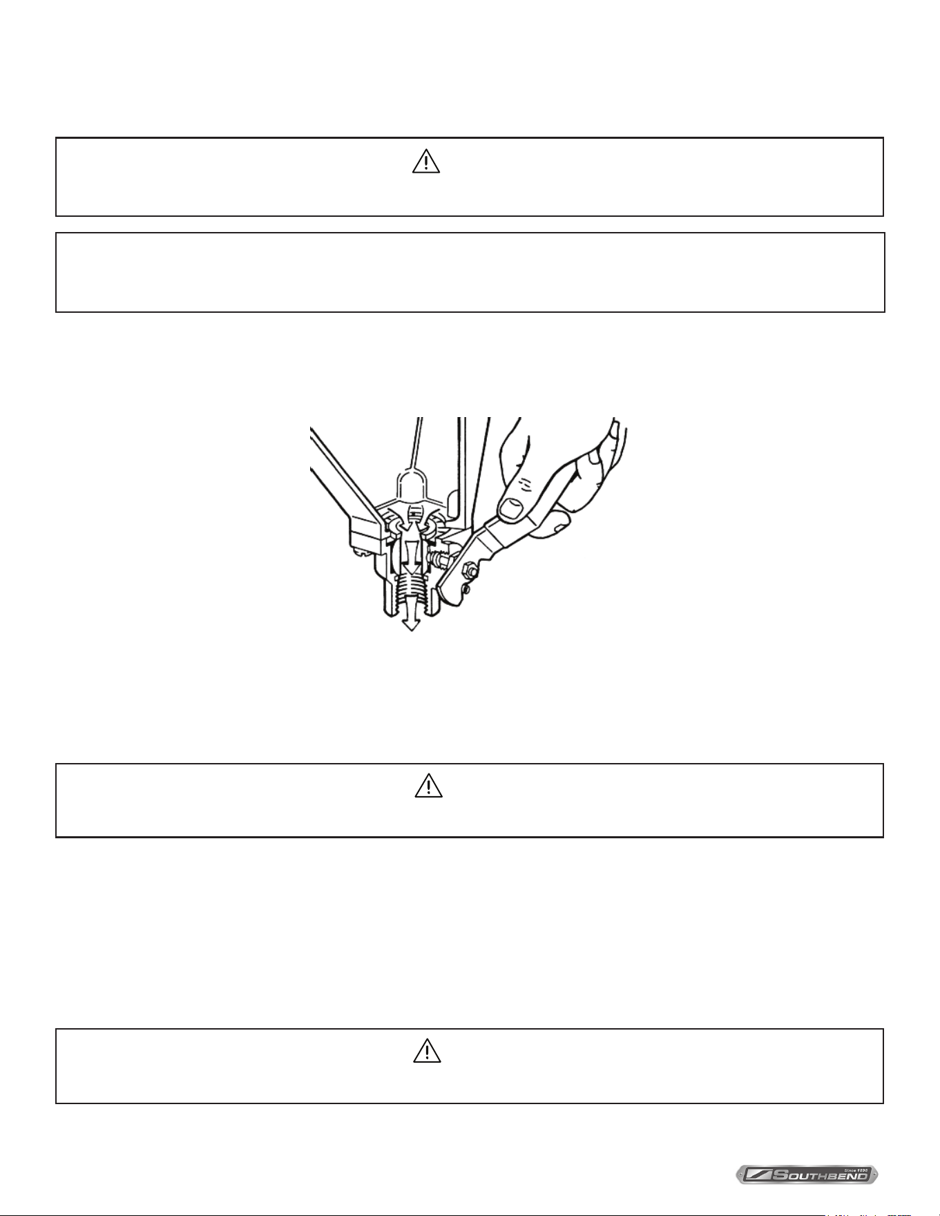
CAUTION
Protect yourself. When ushing control, hot water and steam will ow out of the drain.
When ushing control, note water level in gauge glass, allow the boiler to ll if necessary, and also to come up to
temperature.
Before ushing control, note that water level in gauge glass is within operating range and the boiler pressure is at least
6 psi. While the boiler is being red, open blowdown valve at bottom of control by rotating the handle counterclockwise
about 1/4 turn to fully open the valve.
Opening the blowdown valve also checks the cut-o operation. Float should drop shutting burners o, hot water and
steam will ow out the drain ushing away sediment.
CAUTION
If burner does not shut o during blowdown, immediately discontinue use of appliance and call for service.
NOTICE
Contact the factory, the factory representative or a local service company to perform maintenance and repairs should
the appliance malfunction. Refer to warranty terms.
Maintenance

INSTALLATION & OPERATION MANUAL 10122-SB REV 0 (11/21)
PAGE
17
OF 24
Gas Fired Pressureless Cooker with Direct Steam Kettles Maintenance
Continue draining water for about fteen (15) seconds, from control until water is clean. Manually close valve. Recheck gauge
glass. If water level has dropped signicantly, wait for the boiler to restore water level and pressure and repeat if necessary.
1. Safety relief valve should be tripped during operation periodically to assure that it functions properly.
CAUTION
Live steam will escape during this operation and may cause personal injury.
2. If appliance is equipped with a pressure regulator, twice a year the hex plug located at the bottom of the regulator
should be removed and the strainer cleaned.
3. Burners should be cleaned on a regular basis to eliminate the accumulation of lint on burner ventures and burner orices.
Descaling Boiler
It is recommended that the boiler should be checked every 90 to 120 days for scale build up. Regular maintenance should
be carried out at this time.
If the boiler has been descaled, a new Anode should be installed in the boiler to help extend its life.
1. With boiler empty, close manual blowdown valve. If appliance is equipped with automatic blowdown, turn water supply
OFF to appliance. Turn power switch ON. This will energize and close blowdown valve.
2. Remove 3/4” pipe plug from tting on left front of boiler.
3. Insert appropriate hose or tube through tting and pour in (1/2) half gallon (U.S.) of CLR Descaling Solution or use the
Optional Deliming Assembly DPA-1 available from your dealer
For appliances equipped with CSD-1, descaling solution must be introduced through hand hole.
4. Replace 3/4” pipe plug securely.
5. Open water supply to appliance allowing water to ll boiler to required level.
6. Let appliance cycle, allow two hours for descaling and cleaning. DO NOT TURN STEAM ON TO THE
COMPARTMENTS.
7. Open both the blowdown and low water level control valves for complete drainage and then close both valves.
Appliance equipped with automatic blowdown - turn OFF power switch and open low water control valve. This will
allow complete drainage. Once drained close water level control valve.
8. Turn appliance switch ON. When boiler is completely lled, turn power switch OFF. This will rinse and drain boiler.
Appliance with manual blowdown valve must be opened to drain.
9. Complete Step 8 twice to assure boiler is completely rinsed.
10. Appliance is now ready for use.
INSTALLATION & OPERATION MANUAL 10122-SB REV 0 (11/21)
PAGE
18
OF 24
Gas Fired Pressureless Cooker with Direct Steam Kettles
Cleaning
WARNING
Disconnect the power supply to the appliance before cleaning or servicing.
CAUTION
Do not use cleaning agents that are corrosive.
CAUTION
The appliance and its parts are hot. Use care when operating, cleaning or servicing the appliance.
WARNING
Never spray water into electric controls.
Kettles
1. Turn steam supply “OFF”.
2. Pre-rinse inside of kettles thoroughly and tilt kettles to remove any food particles.
3. Use a nylon brush. Clean kettle with a mild detergent and warm water rinse. NEVER use steel wool or scouring
powder as it will mark the stainless steel.
4. Tilt kettles and thoroughly rinse the inside draining out detergent solution.
5. Wipe the exterior of kettles with a clean, damp cloth.
6. Dry the entire kettles with a clean dry cloth.
What to do if Surface Rust Appears
Metal utensils should never be used as they will scratch the surface of the equipment and rust may begin to form. To
remove surface accumulation of rust from the inadvertent use of such utensils, the following may be used.
CAUTION
Improper use of this procedure may damage your appliance.
1. Use undiluted white vinegar with a non abrasive scouring pad (plastic) or cloth on the aected area to remove the rust
stains. The appliance should not be heated and remain at room temperature during the entire cleaning process.
2. If the stain resists removal, additional exposure time with vinegar may be required, to a maximum of one hour.
3. Thoroughly wash all the vinegar away with fresh water. Dry the surface completely and allow one hour before using
the appliance to cook.
Following daily and period maintenance procedures will prolong the life of your equipment. Climatic conditions - salt air -
may require more thorough and frequent cleaning or the life of the equipment could be adversely aected.
USE OF CLEANING AGENTS THAT CONTAIN CHLORIDE, ACIDS OR SALTS ARE CORROSIVE AND MAY
CAUSE PITTING AND CORROSION WHEN USED OVER A PERIOD OF TIME. THIS WILL REDUCE THE LIFE OF
THE APPLIANCE.
SHOULD PITTING OR CORROSION OCCUR THIS IS NOT COVERED BY WARRANTY.
Cleaning

INSTALLATION & OPERATION MANUAL 10122-SB REV 0 (11/21)
PAGE
19
OF 24
Gas Fired Pressureless Cooker with Direct Steam Kettles Cleaning
Steamer Compartments
1. Keep exposed cleanable areas of unit clean at all times.
2. Thoroughly wash oven cavities, door liners, and pan racks at the end of each day, or as required, with a mild
detergent and water to prevent bacterial growth and odours.
3. Remove drain screens from inside compartment drains. Using a plastic bottle brush and mild detergent, clean inside
the drain opening ensuring there is no food residue or blockage. Clean the drain screen and replace in its original
position.
4. Wash gasket sealing surface daily with mild detergent to remove harmful food acids.
5. Clean around burner air mixer and orice if lint has accumulated.
6. Visually assure carry over ports are unobstructed.
7. Rinse entire unit and dry. DO NOT GET WATER in electrical box or any electrical component.

INSTALLATION & OPERATION MANUAL 10122-SB REV 0 (11/21)
PAGE
20
OF 24
Gas Fired Pressureless Cooker with Direct Steam Kettles
Adjustments
At least twice a year have an authorized service person clean and adjust the unit for maximum performance.
Calibrate Pressure Switches
Adjustments
NOTICE
Pressure switches are factory set. Calibration is only required if pressure switches are replaced or if adjustment
is required.
Pressure switch range is from 1 to 15 psi.
Adjust all settings to maximum on high signal adjustment screw on pressure switches.
Adjust in the following sequence:
- High limit pressure switch.
- Override pressure switch. (if equipped).
- Operating pressure switch.
- Use relief valve to release pressure from boiler for setting adjustments.
1. HIGH LIMIT PRESSURE SWITCHES
Allow pressure to build until unit shuts off. This should occur at 15 psi. Set the high signal to switch at 14.5 psi
on the gauge.
2. OVERRIDE PRESSURE SWITCHES
Allow pressure to increase to 13 psi. Set the high signal to switch at 13 psi on the gauge and the low signal to 11 psi.
3. OPERATING PRESSURE SWITCHES
Set the high signal to switch at 11 psi on the gauge and the low signal to 9 psi.
4. Release pressure in boiler to below 9 psi. Burner will come on. Once pressure has reached 11 psi, burners will shut
o. Repeat this process several times to make sure burners come on at 9 psi and shut o at 11 psi.
Once completed, pressure switches have been calibrated.
Should your unit not have the High Limit pressure switch, start procedure at Override pressure switch.
CAUTION
Operating, testing, and servicing should only be performed by qualied personnel.

INSTALLATION & OPERATION MANUAL 10122-SB REV 0 (11/21)
PAGE
21
OF 24
Gas Fired Pressureless Cooker with Direct Steam Kettles
Troubleshooting
Door Leaks
1. Check for damage to door gasket.
2. Compartment drain opening or associated piping may be blocked.
Water Accumulates in the Compartment
1. Compartment drain screen clogged. Remove and clean thoroughly and replace.
Water Not Being Supplied to Boiler
1. Water supply is “OFF”.
2. Defective water ll solenoid valve.
3. Water level control clogged or defective, unable to operate ll valve.
4. Check drain valve is closed. Also check that water level control valve is closed.
5. Supply water pressure too low.
Automatic Blowdown Valve Does Not Drain
1. Defective blowdown valve.
2. Heat exchanger build up of scalant clogging drain lines and valve.
Boiler Achieves Pressure Slower than Normal
1. Heavy build up of lime or scalant hampering heat transfer. Call for service to inspect interior of boiler. Should a
considerable amount of scalant be found, have steam lines, water level control and valve also inspected.
Safety Valve Blows
1. Defective safety valve.
2. Pressure too high. Pressure switch requires adjustment (lower) or may be defective.
Burners Produce Carbon Deposits
1. Wrong size orices.
2. Burner air not adjusted properly.
3. Wrong gas supply.
4. Incorrect pressure at supply.
Troubleshooting

INSTALLATION & OPERATION MANUAL 10122-SB REV 0 (11/21)
PAGE
22
OF 24
Gas Fired Pressureless Cooker with Direct Steam KettlesTroubleshooting
Burners Do Not Come On
1. Gas supply to unit is “OFF”.
2. Manual shut o valve is “OFF”.
3. Pilot is out.
4. Power supply is “OFF”.
5. Water level has not been reached. Check water supply and water level control.
6. Pilot may require ame adjustment on option electronic ignition units.
7. If water at proper level, check relay which energizes pressure switch and gas valve.
8. Pressure switch may need to be replaced if relay is operating.
9. Check gas control. If energized but not operating, have replaced.
Pilot Light Does Not Ignite (electronic ignition)
1. Gas control knob is in “OFF” position.
2. Loose or dirty wire connection to ignition module, clean/or tighten.
3. Ignition cable shorting out. Check that it is not in contact with metal or damaged.
4. Defective ignition module.
5. Unit is 100% lock out. Turn o and try in ve minutes.
6. Dirty ame sensor. Clean with emery cloth.
7. Pilot burner/ignitor sensor, cracked ceramic insulator. Have replaced.
8. Check for too much draft in room.
Kettle Does Not Heat
1. Steam control valve not turned on.
2. Steam trap not closing.
3. Steam trap not opening to release condensate water.
4. Boiler not producing enough steam pressure.
Kettle Leaks Steam
1. “O” rings are worn. Replace.
2. Steam valve seat worn. Replace seat.

INSTALLATION & OPERATION MANUAL 10122-SB REV 0 (11/21)
PAGE
23
OF 24
Gas Fired Pressureless Cooker with Direct Steam Kettles
Notes
INSTALLATION & OPERATION MANUAL 10122-SB REV 0 (11/21)
PAGE
24
OF 24
Gas Fired Pressureless Cooker with Direct Steam Kettles
GCX-2S-(6, 10), GCX-10S-(6, 10),
GCX-2S-6-(6, 10) & GCX-10S-6-(6, 10)
Gas Fired Pressureless Cooker
with Direct Steam Kettles
A product with the Southbend Steam name incorporates the best in durability and low maintenance. We all recognize,
however, that replacement parts and occasional professional service may be necessary to extend the useful life of this
appliance. When service is needed, contact a Southbend Steam Authorized Service Agency, or your dealer. To avoid
confusion, always refer to the model number, serial number, and type of your appliance.
SOUTHBEND STEAM
A Middleby Company
1100 Old Honeycutt Road Fuquay-Varina, North Carolina 27526 USA
www.southbendnc.com