i
Diana series robot
Document version: V1.0. 2

Diana Series Robot User Manual
i
Contents
1. SAFETY ................................................................................................................................ - 1 -
1.1. SAFETY REGULATION S ............................................................................................................. - 1 -
1.2. SAFETY SIGNS ......................................................................................................................... - 3 -
1.3. PERSONNEL REQUIREMENTS ................................................................................................... - 4 -
1.4. PRECAUTIONS ......................................................................................................................... - 5 -
1.5. EMERGENCY STOP .................................................................................................................. - 8 -
2. INTENDED USE AND PLACEMENT CONDITIONS ....................................................... - 9 -
3. ROBOT SYSTEM .............................................................................................................. - 11 -
4. TECHNICAL SPECIFICATIONS ..................................................................................... - 12 -
4.1. TECHNICAL SPECIFICATIONS ................................................................................................. - 12 -
4.2. ROBOT ARM DIMENSIONS ................................................................................................. - 14 -
4.3. C ONTROLLER DIMENSIONS .............................................................................................. - 16 -
5. INSTALLATION ................................................................................................................. - 17 -
5.1. ROBOT ARM MOUNTING AND FIXATION ............................................................................... - 17 -
5.2. END -EFFECTOR MOUNTING AND FIXATION ...................................................................... - 18 -
6. CONTROL LER ELECTRICAL INTERFACES .................................................................. - 20 -
7. TRANSPORT ..................................................................................................................... - 21 -
8. FCC STATEMENT ............................................................................................................ - 22 -
9. DISCLAIMER .................................................................................................................... - 23 -
Diana Series Robot User Manual
ii
Diana Series Robot User Manual
- 1 -
1. Safety
1.1. Safety Regulation s
The information in this manual does not include the design, installation, and
operation of a complete robot integration system, nor does it include all
peripheral devices that may affect the safety of such a system. The design and
installation of the compl ete system must comply with the safety requirements
established by the standards and regulations of the country where the robot is
used.
In particular, Agile Robots is not responsible for any injury or damage caused
by any of the following reasons:
➢ Use this product for purposes other than those specified.
➢ Failure to use the robot as prescribed.
➢ Operating the robot when safety devices are defective or not
functioning properly.
➢ Unauthorized modifications to the robot design.
➢ Repairs of the robot or its parts performed by inexperienced or
unqualified personnel.
➢ Installation of non - original parts or accessories.
➢ Natural disasters such as fire, earthquake, tsunami, lightning, strong
winds, or floods.
The integrator of Agile Robots is responsible for ensuring compliance with
relevant national laws and regulations, and for ensuring that no significant
hazards exist in the complete robot integration system. This includes but is not
limited to the followin g:
➢ Conduct a comprehensive risk assessment of the entire robot
integration system.
➢ Connect other machinery and additional safety devices defined in the
Diana Series Robot User Manual
- 2 -
risk assessment to the robot integration system for coordinated use.
➢ Perform appropriate safety settings in the software.
➢ Ensure that users do not modify any safety measures.
➢ Verify that the design and settings of the entire robot integration
system are accurate.
➢ Create operational specifications for the complete system, with clear
usage process descriptions.
➢ Use appropriate methods during final installation to eliminate hazards
or reduce them to an acceptable level, and communicating any
residual risks to the end user.
➢ Provide training to users and staff.
➢ Mark the relevant equipment of the robot integration system with the
integrator's relevant identification and contact information.
When performing a risk assessment, the integrator shall consider the following
potential risks:
➢ Consequences of end -effector dropping from the robot
➢ Consequences of the robot colliding with other equipment within the
workspace
➢ Consequences of personnel tripping due to improper on - site cable
management
➢ Scratches caused by contact with the robot
Only personnel with the appropriate qualifications may handle and set up the
robot and related machinery. In addition, all relevant national laws and
regulations must be strictly observed. Before use, user shall carefully read this
manual and related instructions, and operate the robot correctly. After reading,
keep the manual properly for future reference.
Any safety information contained in this manual shall not be regarded as a
Diana Series Robot User Manual
- 3 -
guarantee of the robot's safety. Even if all safety instructions are followed, the
robot may still cause injury or damage.
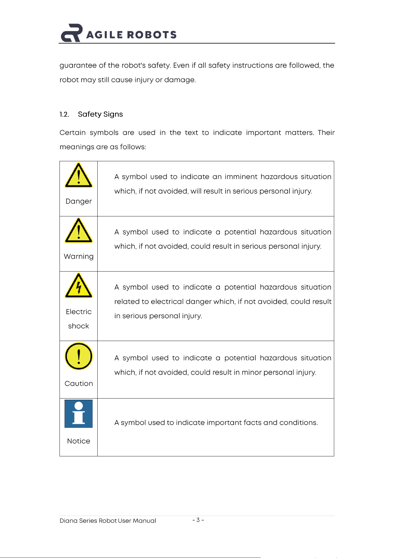
1.2. Safety Signs
Certain symbols are used in the text to indicate important matters. Their
meanings are as follows:
Danger
❑ A symbol used to indicate an imminent hazardous situation
which, if not avoided, will result in serious personal injury.
Warning
❑ A symbol used to indicate a potential hazardous situation
which, if not avoided, could result in serious personal injury.
Electric
shock
❑ A symbol used to indicate a potential hazardous situation
related to electrical danger which, if not avoided, could result
in serious personal injury.
Caution
❑ A symbol used to indicate a potential hazardous situation
which, if not avoided, could result in minor personal injury.
Notice
❑ A symbol used to indicate important facts and conditions.
Diana Series Robot User Manual
- 4 -
1.3. Personnel Requirements
Only personnel who have received appropriate training may design and set up
the robot. Appropriately trained personnel refers to those who have received
training provided by the company or its agents, covering electrical, mechanical,
and other hazards iden tified in the risk assessment.
Personnel under the influence of alcohol, medication, or other intoxicating
substances must not install, maintain, repair, or operate the robot.
Personnel must have received training on the robot as well as on responses to
emergencies or abnormal situations.
Personnel must not wear loose clothing, and long hair must be properly tied
back to reduce the risk of entanglement.
Use personal protective equipment correctly.
Diana Series Robot User Manual
- 5 -
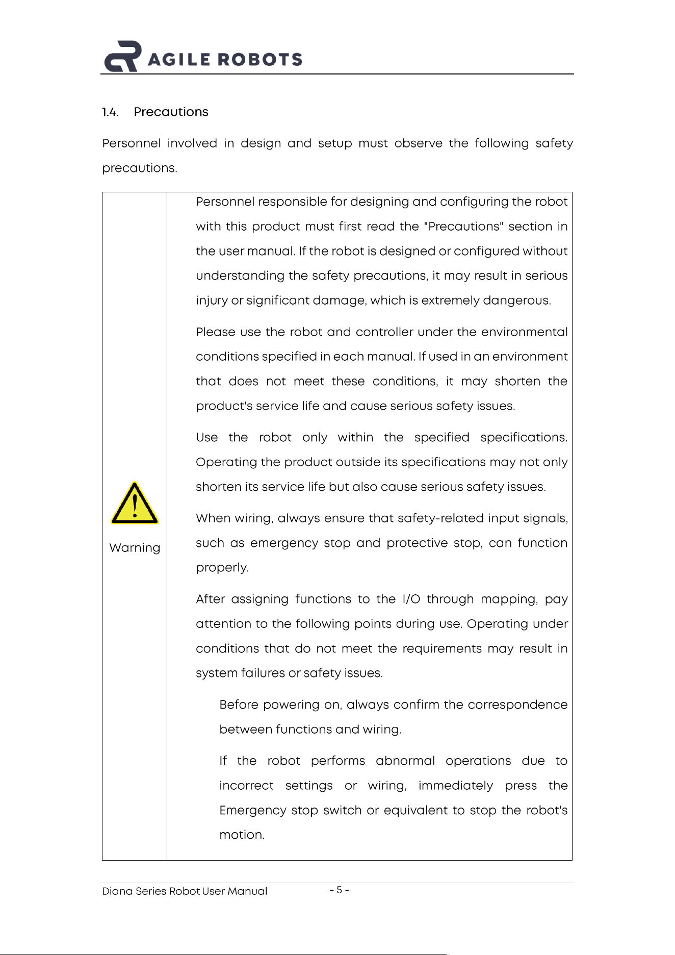
1.4. Precautions
Personnel involved in design and setup must observe the following safety
precautions.
Warning
❑ Personnel responsible for designing and configuring the robot
with this product must first read the "Precautions" section in
the user manual. If the robot is designed or configured without
understanding the safety precautions, it may result in serious
inju ry or significant damage, which is extremely dangerous.
❑ Please use the robot and controller under the environmental
conditions specified in each manual. If used in an environment
that does not meet these conditions, it may shorten the
product's service life and cause serious safety issues.
❑ Use the robot only within the specified specifications.
Operating the product outside its specifications may not only
shorten its service life but also cause serious safety issues.
❑ When wiring, always ensure that safety - related input signals,
such as emergency stop and protective stop, can function
properly.
❑ After assigning functions to the I/O through mapping, pay
attention to the following points during use. Operating under
conditions that do not meet the requirements may result in
system failures or safety issues.
➢ Before powering on, always confirm the correspondence
between functions and wiring.
➢ If the robot performs abnormal operations due to
incorrect settings or wiring, immediately press the
Emergency stop switch or equivalent to stop the robot's
motion.
Diana Series Robot User Manual
- 6 -
Danger
❑ The installation and commissioning of the robot must be
performed by professional operators in accordance with this
manual and relevant standards.
Electric
shock
❑ Except for maintenance work, do not open the cover of the
control ler. There are high -voltage areas inside the control ler.
Even when the power is turned off, there is still a risk of electric
shock. Always wait at least 30 seconds after shutting off the
power before opening the control ler cover.
❑ Always connect or disconnect cables with the control ler power
turned off. Performing this operation with the power on poses
a risk of electric shock or may cause malfunctions.
❑ Securely connect the cables. Do not place heavy objects on
the cables, excessively bend them, pull them forcibly, or pinch
them. Otherwise, the cables may be damaged, broken, or have
poor contact, which could result in abnormal robot operation
or electric shock.
❑ Power plugs for the factory must be installed by personnel with
professional knowledge and skills. When installing the power
plug, always connect the ground wire of the AC power cable
to the grounding terminal of the distribution system. Failure to
properl y connect the ground wire may result in electric shock.
Diana Series Robot User Manual
- 7 -
Personnel engaged in operation and maintenance must observe the following
safety precautions.
Warning
❑ Do not enter the robot's operating area while the power is on.
Even if the robot appears to have stopped, it may still move,
which is extremely dangerous and could cause serious safety
issues.
❑ When manually controlling the robot with a teach pendant
(including a software teach pendant), the operator must
carefully monitor the robot's movements.
❑ Ensure that the end -effector is firmly installed. After
installation, check its mounting condition.
❑ Ensure that operators are familiar with the location of the
Emergency stop switch , as well as the startup and recovery
methods. If the robot operates abnormally, immediately press
the Emergency stop switch .
❑ Ensure that the robot's installation angle, end - effector weight,
center - of - gravity offset, and safety configurations match the
current operating conditions.
❑ Before using the robot for the first time, check the integrity of
the robot system, equipment, safety functions, and the
appropriateness of the corresponding settings.
❑ Before using the robot for the first time, conduct a new risk
assessment and keep the relevant records.
❑ When the robot works in coordination with other equipment, it
is recommended to set up a temporary testing area outside
the equipment workspace and first perform independent
testing and verification of the robot's safety functions and
programming within th at area.
Diana Series Robot User Manual
- 8 -
Danger
❑ If the robot performs abnormal actions during operation,
immediately press the Emergency stop switch . Continuing to
operate the robot during abnormal motion may result in
serious injury or major damage, and is extremely dangerous.
Electric
shock
❑ Except for maintenance work, do not open the cover of the
control ler. There are high -voltage areas inside the control ler.
Even when the power is turned off, there is still a risk of electric
shock. Always wait at least 30 seconds after shutting off the
power before opening the control ler cover.
❑ Do not connect or disconnect connectors while the power is
on. Doing so may cause abnormal robot operation, which is
extremely dangerous. In addition, performing this operation
with the power on may result in electric shock or malfunction.
❑ Do not arbitrarily modify the robot's hardware configuration.
Any unauthorized modifications may cause unforeseeable
potential hazards. Agile Robots assumes no responsibility for
any unauthorized modifications made to the robot in any form.
1.5. Emergency Stop
If any abnormal situation occurs during robot operation, the user must
immediately press the Emergency stop switch to halt robot motion. Before
restarting the robot, verify that all faults have been completely resolved.
When the Emergency stop switch is pressed, the robot's servo system power will
be cut off and the joint brakes will be engaged. The Emergency stop switch is
intended only for use in hazardous situations. In normal operation, to stop the
robot, the stop button in the control software system must be used.
The emergency stop function is a supplementary protective measure and must
not replace other safeguards and safety functions.
Diana Series Robot User Manual
- 9 -
2. Intended Use and Placement Conditions
Agile Robots' robotic products are designed for industrial applications,
intended for manipulating tools and fixtures, or for processing and transferring
parts and products. Any application outside the intended use is not permitted,
including but not limited to the following:
➢ Use in potentially explosive environments.
➢ Use in medical or life -critical applications.
➢ Use in applications involving direct contact with food, beverages, or
pharmaceutical products.
➢ Use in applications involving the movement or handling of people or
animals.
➢ Use in applications that have a significant impact on society or the
public.
➢ Use as climbing equipment.
➢ Before performing the risk assessment.
➢ Use beyond the specified limits.
➢ Operation outside the permitted parameter settings.
To maintain the functionality of the robot and ensure safe use, an appropriate
environment is required. Place the control ler in a location that meets the
following conditions:
➢ The control ler is not of cleanroom -grade specification. When installed
in a cleanroom, take appropriate measures to make it suitable for the
cleanroom environment, such as covering the control ler with a housing
equipped with exhaust or cooling structures.
➢ Place the control ler near a power socket in a location where the plug
can be easily attached and detached.
➢ Install it indoors in a well -ventilated area, leaving at least 50 mm of
Diana Series Robot User Manual
- 10 -
clearance around the control ler fan to ensure smooth airflow.
➢ Protected from direct sunlight and radiant heat.
➢ Free from oil mist, smoke, salt, metal dust, or similar contaminants in the
air.
➢ Kept away from flammable or corrosive liquids and gases.
➢ Protected from impacts and vibrations.
➢ Not located near relays, contactors, or other sources of electrical
interference, and not exposed to strong magnetic or electric fields.
Diana Series Robot User Manual
- 11 -
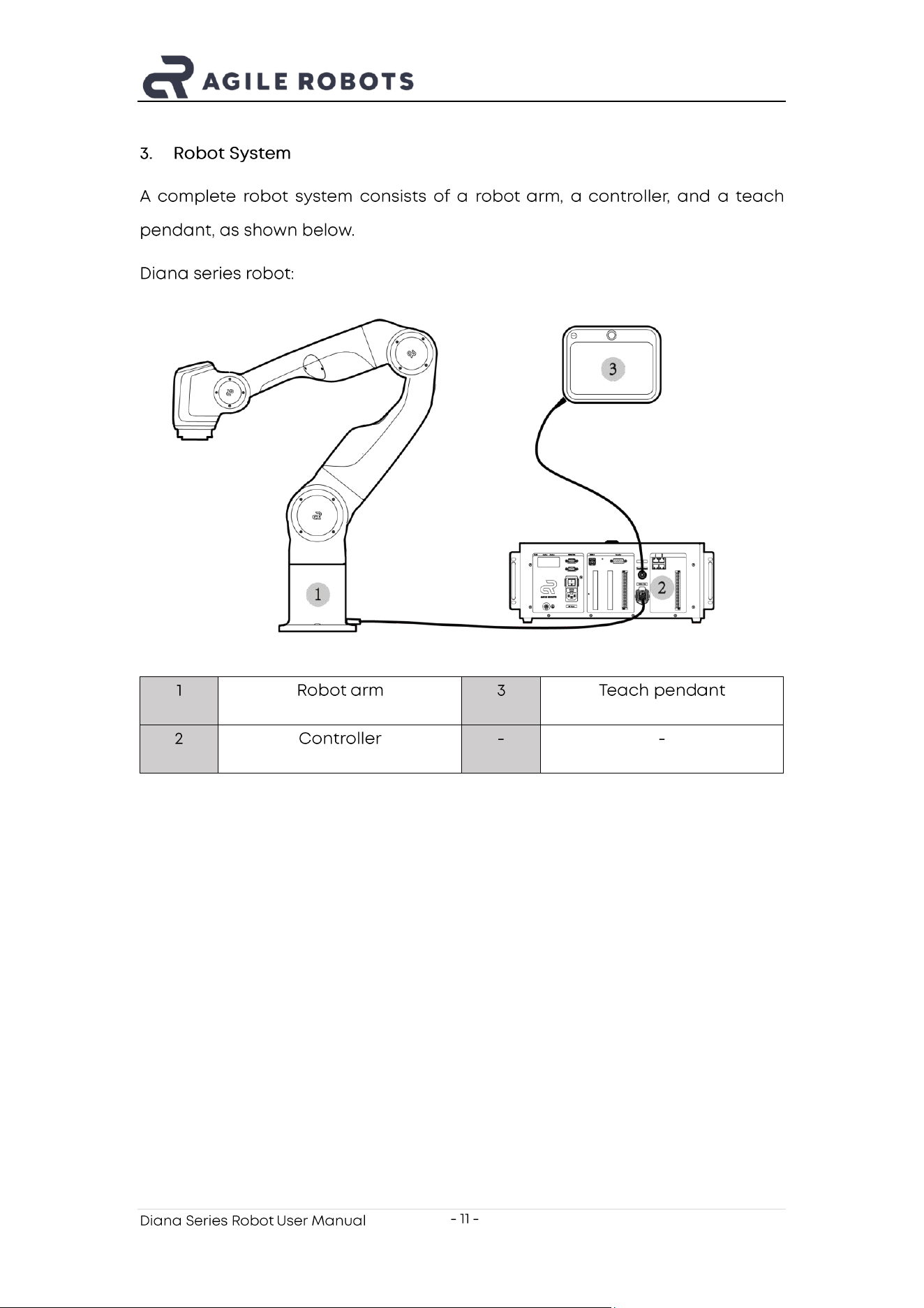
3. Robot System
A complete robot system consists of a robot arm , a controller , and a teach
pendant, as shown below.
Diana series robot:
1
Robot arm
3
Teach pend a nt
2
Controller
-
-
Diana Series Robot User Manual
- 12 -
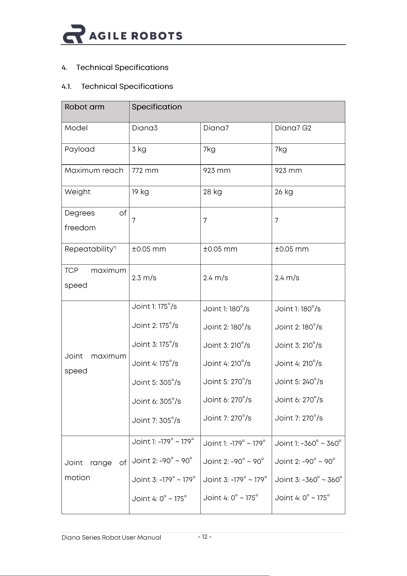
4. Technical Specifications
4.1. Technical Specifications
Robot arm
Specification
Model
Diana3
Diana7
Diana7 G2
Payload
3 kg
7kg
7kg
Maximum reach
772 mm
923 mm
923 mm
Weight
19 kg
28 kg
26 kg
Degrees of
freedom
7
7
7
Repeatability
*1
±0.05 mm
±0.05 mm
±0.05 mm
TCP maximum
speed
2.3 m/s
2.4 m/s
2.4 m/s
Joint maximum
speed
Joint 1: 175°/s
Joint 2: 175°/s
Joint 3: 175°/s
Joint 4: 175°/s
Joint 5: 305°/s
Joint 6: 305°/s
Joint 7: 305°/s
Joint 1: 180°/s
Joint 2: 180°/s
Joint 3: 210°/s
Joint 4: 210°/s
Joint 5: 270°/s
Joint 6: 270°/s
Joint 7: 270°/s
Joint 1: 180°/s
Joint 2: 180°/s
Joint 3: 210°/s
Joint 4: 210°/s
Joint 5: 2 40°/s
Joint 6: 270°/s
Joint 7: 270°/s
Joint range of
motion
Joint 1: -179° ~ 179°
Joint 2: - 90° ~ 90°
Joint 3: -179° ~ 179°
Joint 4: 0° ~ 175°
Joint 1: -179° ~ 179°
Joint 2: - 90° ~ 90°
Joint 3: -179° ~ 179°
Joint 4: 0° ~ 175°
Joint 1: - 360° ~ 360°
Joint 2: - 90° ~ 90°
Joint 3: -360° ~ 360°
Joint 4: 0° ~ 175°
Diana Series Robot User Manual
- 13 -
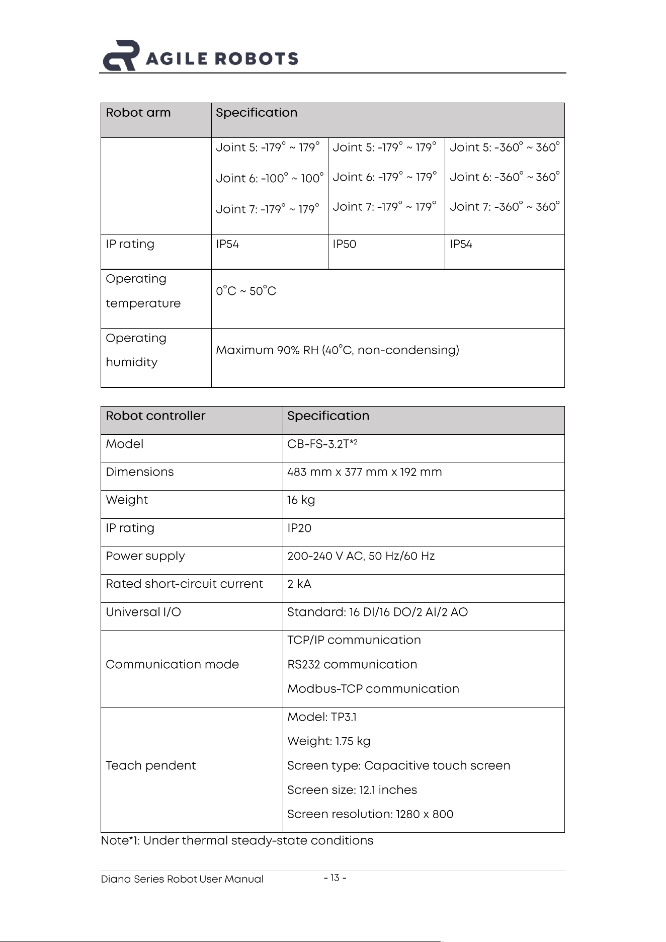
Robot arm
Specification
Joint 5: -179° ~ 179°
Joint 6: -100° ~ 100°
Joint 7: -179° ~ 179°
Joint 5: -179° ~ 179°
Joint 6: -179° ~ 179°
Joint 7: -179° ~ 179°
Joint 5: -360° ~ 360°
Joint 6: -360 ° ~ 360°
Joint 7: - 360° ~ 360°
IP rating
IP54
IP50
IP54
Operating
temperature
0°C ~ 50°C
Operating
humidity
Maximum 90% RH (40°C, non - condensing)
Robot controller
Specification
Model
CB - FS - 3.2T*
2
Dimensions
483 mm x 377 mm x 192 mm
Weight
16 kg
IP rating
IP20
Power supply
200-240 V AC, 50 Hz/60 Hz
Rated short - circuit current
2 kA
Universal I/O
Standard: 16 DI/16 DO/2 AI/2 AO
Communication mode
TCP/IP communication
RS232 communication
Modbus -TCP communication
Teach pendent
Model: TP3.1
Weight: 1.75 kg
Screen type: Capacitive touch screen
Screen size: 12.1 inches
Screen resolution: 1280 x 800
Note*1: Under thermal steady -state conditions
Diana Series Robot User Manual
- 14 -
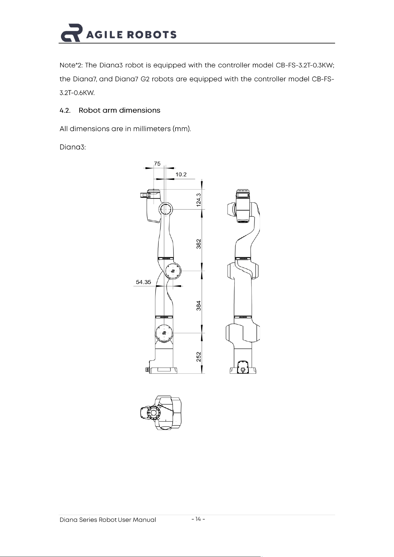
Note* 2: The Diana3 robot is equipped with the controller model CB - FS - 3.2T-0.3KW;
the Diana7, and Diana7 G2 robots are equipped with the controller model CB - FS -
3.2T- 0.6KW .
4.2. Robot arm d imensions
All dimensions are in millimeters (mm).
Diana3:
Diana Series Robot User Manual
- 15 -
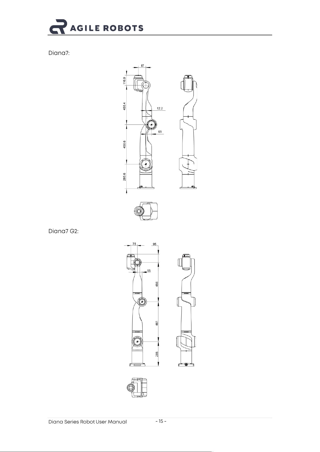
Diana7:
Diana7 G2:
Diana Series Robot User Manual
- 16 -
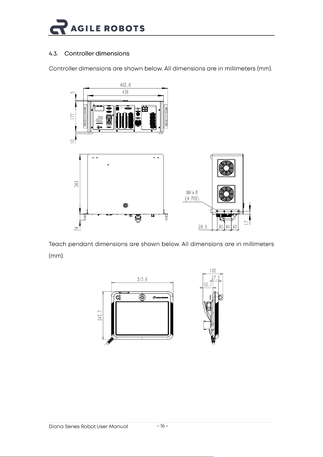
4.3. Controller d imensions
C ontroller dimensions are shown below. All dimensions are in millimeters (mm).
Teach pendant dimensions are shown below. All dimensions are in millimeters
(mm).
Diana Series Robot User Manual
- 17 -
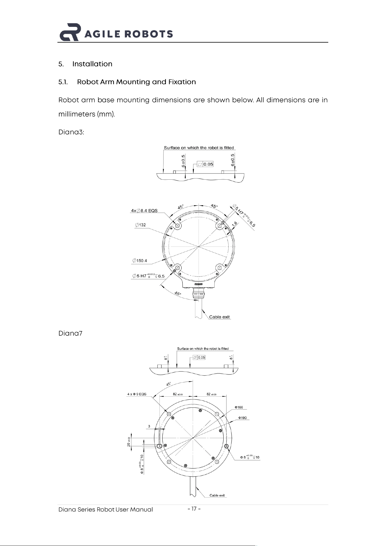
5. Installation
5.1. Robot Arm Mounting and Fixation
Robot arm b ase mounting dimensions are shown below. All dimensions are in
millimeters (mm).
Diana3:
Diana7 :
Diana Series Robot User Manual
- 18 -
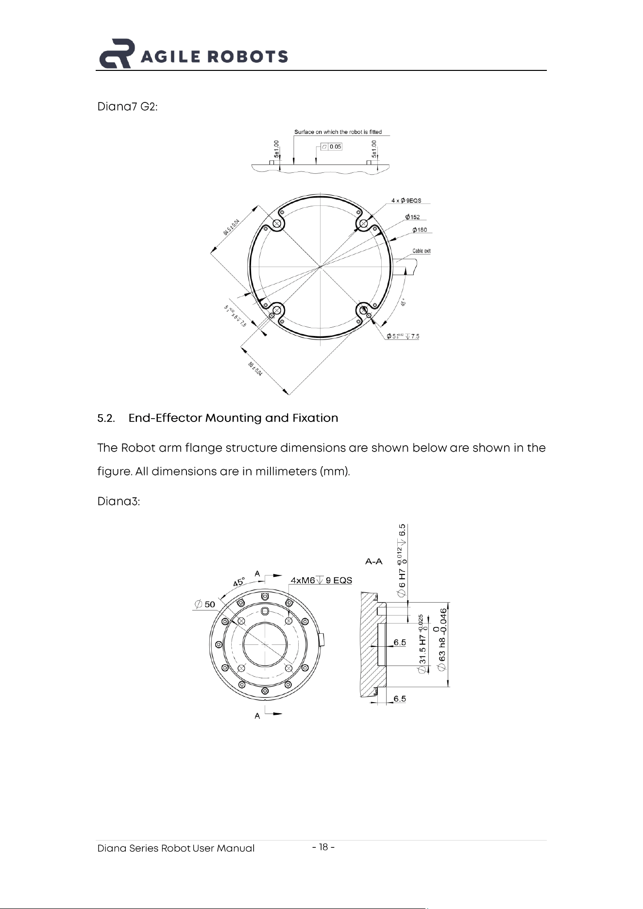
Diana7 G2:
5.2. End - Effector Mounting and Fixation
The Robot arm flange structure dimensions are shown below are shown in the
figure. All dimensions are in millimeters (mm).
Diana3:
Diana Series Robot User Manual
- 19 -
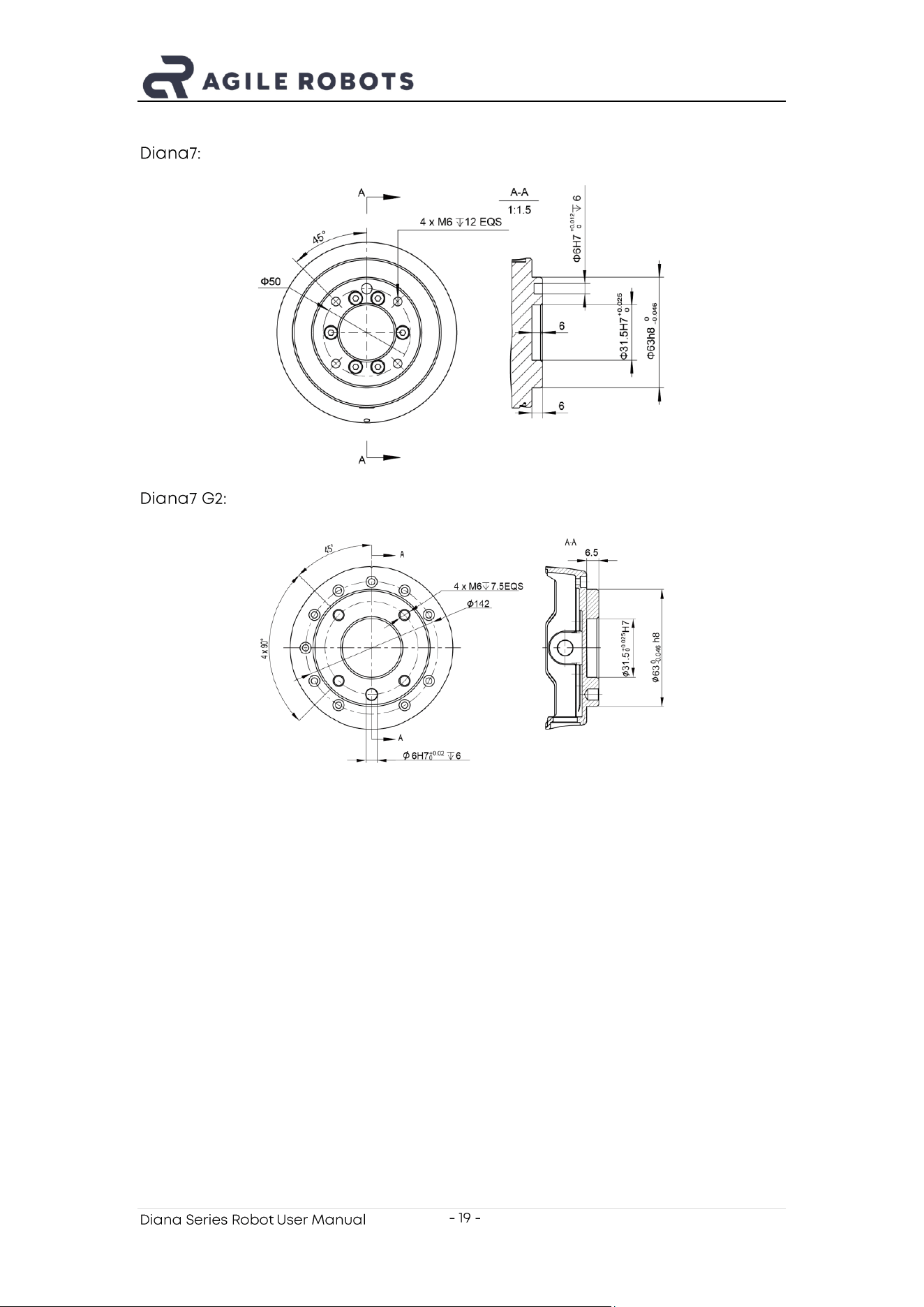
Diana7:
Diana7 G2:
Diana Series Robot User Manual
- 20 -
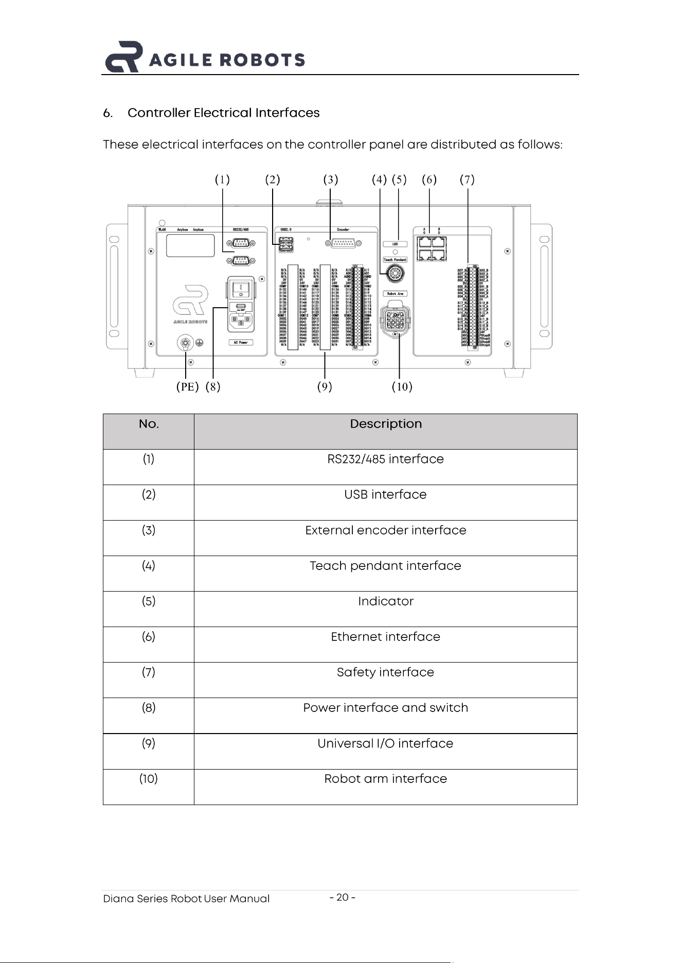
6. Control ler Electrical Interfaces
These electrical interfaces on the controller panel are distributed as follows:
No.
Description
(1)
RS232/485 interface
(2)
USB interface
(3)
External encoder interface
(4)
Teach pendant interface
(5)
Indicator
(6)
Ethernet interface
(7)
Safety interface
(8)
Power interface and switch
(9)
Universal I/O interface
(10)
Robot arm interface
Diana Series Robot User Manual
- 21 -
7. Transport
During transportation, the product should be transported in its original
packaging.
The product packaging should be properly kept for reuse in future
transportation.
Diana Series Robot User Manual
- 22 -
8. FCC statement
Please take attention that changes or modification not expressly approved by
the party responsible for compliance could void the user’s authority to operate
the equipment.
This device complies with Part 15 of the FCC Rules. O peration is subject to the
following two conditions:
(1) This device may not cause harmful interference, and
(2) This device must accept any interference received, including interference
that may cause undesired operation.
Diana Series Robot User Manual
- 23 -
9. Disclaimer
Agile Robots is committed to the continuous improvement of product reliability
and performance. We are constantly conducting research and development,
as well as innovation, to ensure that our robotic technology remains at the
forefront of the industry. To this end, we reserve the right to upgrade our
products and user manuals at any time to reflect the latest technological
advancements and improvements. Please note that we may not issue
individual notifications for every change, but we encourage users to r egularly
check our customer service department for the most updated information.
We strive to ensure the accuracy and reliability of the content in this user
manual to provide more detailed product operation and maintenance
guidelines. However, given the complexity and constant evolution of technology,
we cannot guarantee that there ar e no errors or omissions in the user manual.
If users encounter any issues or have questions when using the product, we
recommend contacting our technical support team directly for assistance.
Agile Robots assumes no legal responsibility for any errors, omissions, or
inaccuracies in the user manual, whether due to negligence, misunderstanding,
or other causes. We advise users to read the manual carefully before using the
product and to follow al l instructions and safety guidelines.
Our ongoing improvements and updates to the user manual demonstrate our
commitment to customer satisfaction and service quality. We appreciate your
understanding and support and welcome any feedback to help us improve our
products and services.
Diana Series Robot User Manual
- 24 -
Agile Robots SE
Plinganserstrasse 134, 81369 Muenchen, Germany