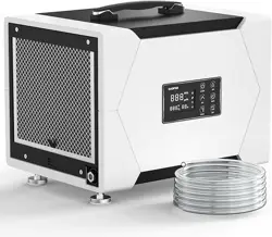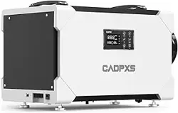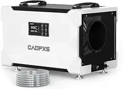
CADPXS Remois XP Series
Installation and Operation Manual
READ AND SAVE THESE INSTRUCTIONS
Add: 2550 N LOOP FWY #108 HOUSTON TX 77092
Tel: (888) 503-0618
E-mail: [email protected]
Specications subject to change without notice.
Remois XP70 Remois XP125
Remois XP145


TABLE OF CONTENTS
Important Notes 1
Warranty Registration 1
Power Supply 1
Working Principle 2
Installation Requirements 2
Button Functions 3
Function Description 5
Maintenance 13
Energy Saving Tips 19
Optional Remote Controller 19
A1-A6 Functions 20
Function Description 22
Limited Warranty 23
Limited Warranty Exclusions 23
Circuit Diagram 24

- 1 -
IMPORTANT NOTES
1. Always connect the dehumidier to a grounded power supply (required for all electrical
appliances). Failure to use a grounded power supply will void the warranty.
2. Repairs should only be performed by qualied technicians.
3. If ooding occurs, ensure the dehumidier is thoroughly dried before reconnecting to power.
4. Do not insert objects or ngers into air intake or exhaust vents.
5. Do not clean the unit with water. Unplug it and use a damp cloth to clean the exterior.
6. Do not stand on or place objects on top of the dehumidier.
7. Do not use extension cords or plug adapters.
8. Perform all maintenance with the unit powered o unless otherwise specied.
WARRANTY REGISTRATION
Your dehumidier has an extensive warranty. Record the model, serial number, and purchase
date, which can be found on the data label on the unit’s side.
Model:
Remois XP70 / Remois XP125 / Remois XP145
Serial Number: __________________ Date of Purchase: __________________
For additional questions concerning your dehumidier, the following options are available:
• Contact your installing contractor
• E-mail: [email protected]
POWER SUPPLY
Power Supply: 115 V, 60 Hz AC, Single Phase
Outlet Requirement: 3-Prong, GFCI
Circuit Protector: 15 Amps
WARNING:
240 V AC may cause serious injury from electric shock.
To reduce risk of injury:
1. Disconnect electrical power before servicing .
2. Only plug unit into grounded electrical circuit .
3. Do not use an extension cord.
4. Do not use a plug adapter.

- 2 -
WORKING PRINCIPLE
The Dehumidier utilizes its integral humidistat to monitor the conditioned space. When the
relative humidity goes above the selected set point, the dehumidier will energize. Air is drawn
across an evaporator coil, which is cooler than the dew point of air. This means moisture will
condense out of the air. The air is then reheated through the condenser coil and distributed
back into the room.
INSTALLATION REQUIREMENTS
1. The workspace should be enclosed.
2. Ensure at least a 6-inch clearance for intake and exhaust vents.
3. Position centrally for optimal eciency.
4. Operate only in an upright, level position.
- 3 -
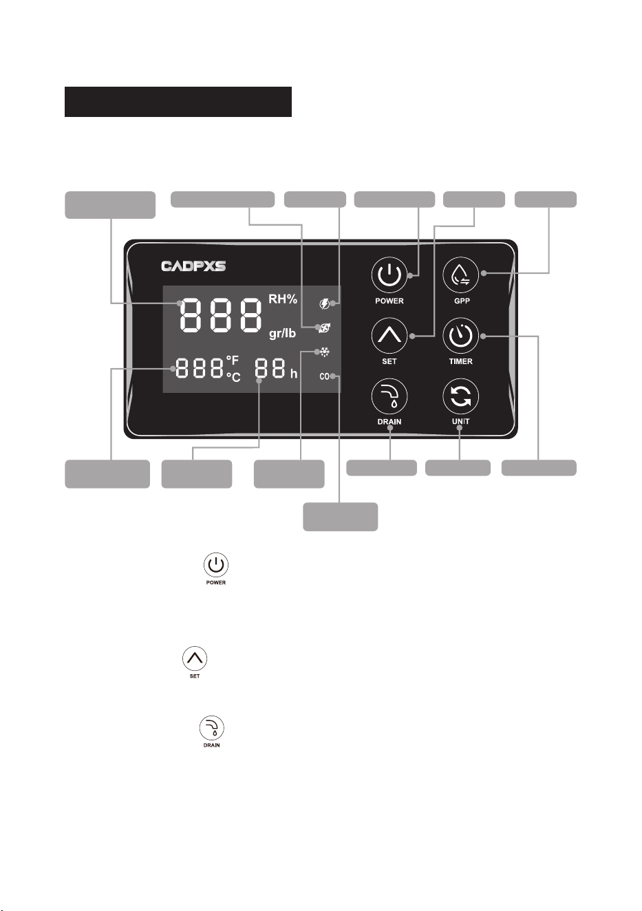
BUTTON FUNCTIONS
The unit will beep each time a button is pressed to conrm the action.
Humidity Display
Window
POWER Button
DRAIN Button
Defrost
Indicator Light
Timer Display
Window
Temperature
Display Window
SET ButtonPower Light
Continuous
Indicator Light
Pump Indicator Light
GPP Button
TIMER ButtonUNIT Button
1. POWER Button
Press this button to turn the dehumidier on or o.
Press this button to cancel the programmed timer function.
2. SET Button
Press this button to adjust the set humidity level or moisture content.
3. DRAIN Button
Press and hold this button for 3 seconds to turn the water pump feature on or o.Once the
pump is turned on, you can press the DRAIN button briey to start a 28-second drainage
cycle.
Note:
Make sure the drain tube is properly connected and installed this is required for the
pump to work correctly.

- 4 -
4. GPP Button
Press this button to turn GPP mode on or o. When activated, the unit will display and
control humidity based on actual moisture content (Grains Per Pound).
Note:
GPP mode is ideal for precise moisture control, especially in restoration or drying
projects.
5. TIMER Button
Press this button to set the desired timer for automatic shutdown. (For details, see the
timer function.)
6. UNIT Button
Press this button to to toggle between °F and °C.
7. Humidity Display Window
Displays ambient humidity, humidity set point, and error codes (E1, E3, E4, E5).
8. Temperature Display Window
Displays ambient temperature, coil temperature, and error codes LO, H1.
Displays “- - -” when Error Code E1 is triggered.
9. Timer Display Window
Shows the selected timer duration and counts down the remaining time.
10. Key Combination
Press and hold both the “GPP Button” and “SET Button”:
• The Temperature Display Window will display coil temperature.
• Displaying -10°C or 14°F indicates a coil temperature sensor failure.
- 5 -
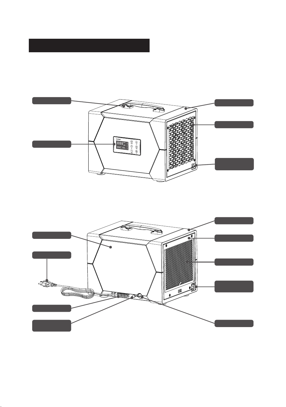
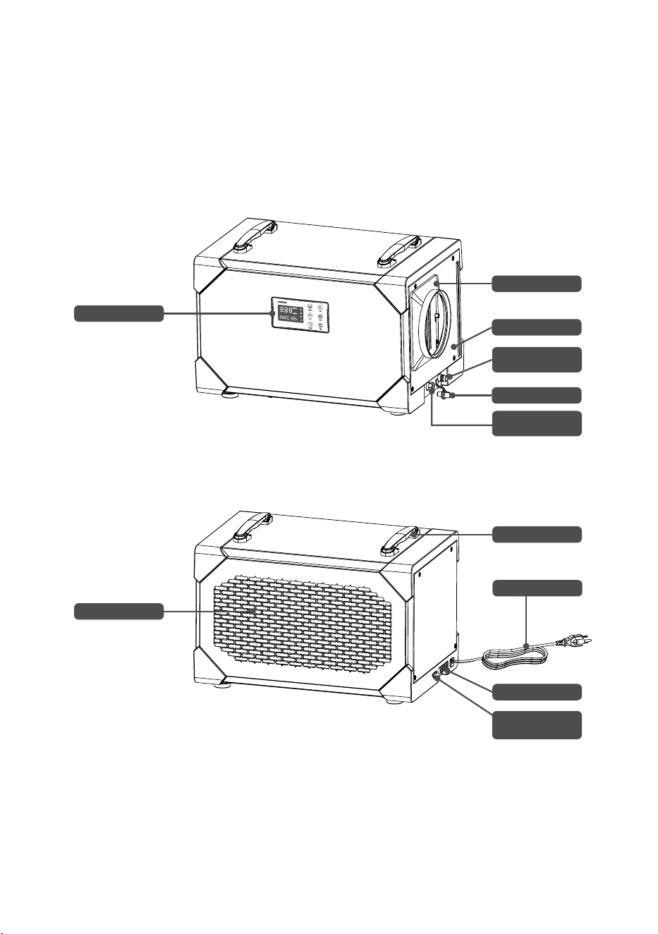
FUNCTION DESCRIPTION
Handle
Decorative Cover
Air Outlet Panel
Control Panel
Rear Side Cover
Power Cord
A1-A6 Port
Gravity Drainage
Outlet
Water Plug
Filter
Air Intake Panel
Decorative Cover
Pump Drainage
Outlet
Remois XP70
Front View
Back View
Remote Control
Port
* All illustrations in this manual are for illustrative purposes only. The actual appearance and
functions may vary according to the product purchased.
- 6 -
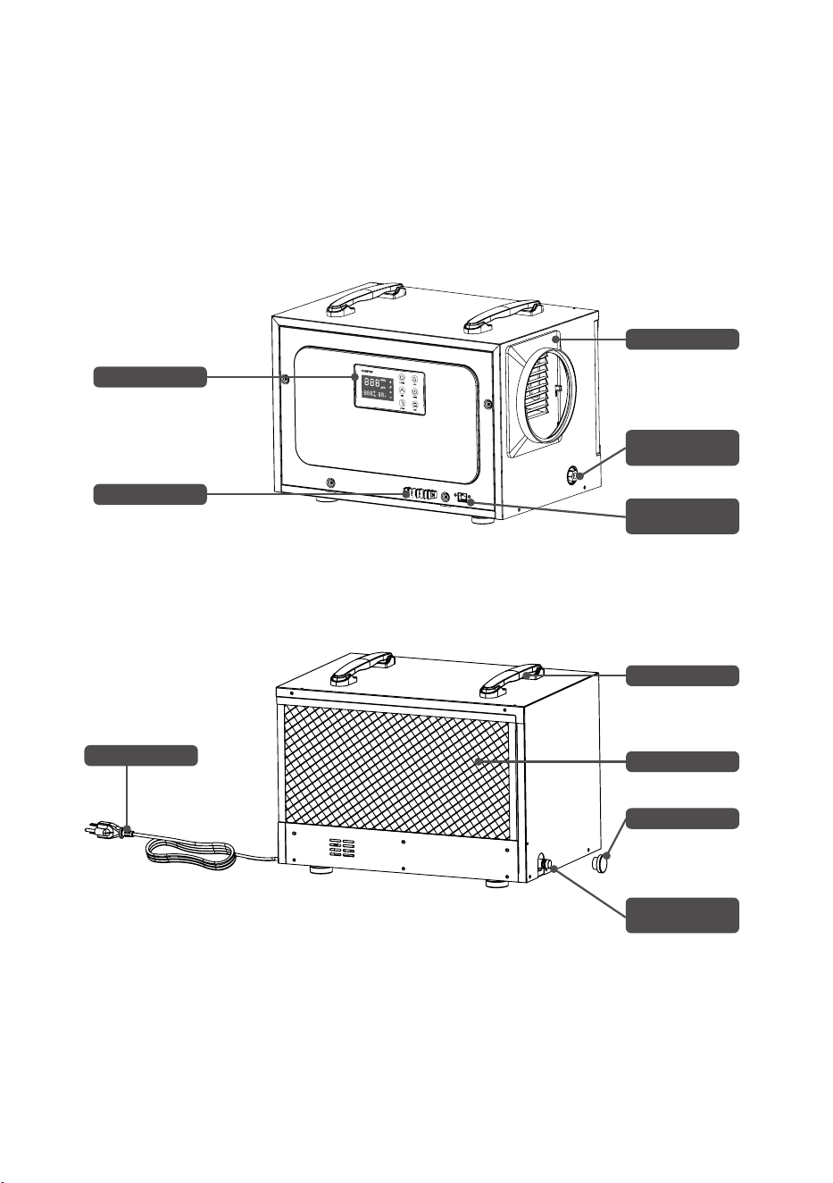
Remois XP125
Front View
Back View
Control Panel
A1-A6 Port
Duct Adapter
Water Plug
Pump Drainage
Outlet
Pump Drainage
Outlet
Remote Control
Port
Power Cord
Filter
Handle
* All illustrations in this manual are for illustrative purposes only. The actual appearance and
functions may vary according to the product purchased.
- 7 -
Remois XP145
Front View
Back View
Control Panel
Filter
Duct Adapter
Air Outlet Panel
Water Plug
Gravity Drainage
Outlet
Pump Drainage
Outlet
Handle
A1-A6 Port
Power Cord
* All illustrations in this manual are for illustrative purposes only. The actual appearance and
functions may vary according to the product purchased.
Remote Control
Port

- 8 -
How to Set the Humidity Level
Turn on the machine, then press the “SET” button. The humidity display will ash, showing
the current set humidity level.
Adjust the Humidity
While the display is ashing (within 3 seconds), press the “SET” button repeatedly to
change the setting:
• Humidity range: CO → 35% to 90% → CO (1% steps)
• Moisture content: CO → 25% to 200% → CO (5% steps)
• Tip:
Hold the button to scroll faster.
Once you reach the desired setting, release the button. After 3 seconds, the display will
stop ashing and show the current room humidity.
When the target humidity is reached, the machine will enter standby mode and the power
light will ash. If humidity rises again, the unit will automatically resume operation based
on the set level.
Enabling Continuous Dehumidication Mode
To set the unit to Continuous Dehumidication Mode, start by turning the machine on.
Press either the “SET” button, and the display will begin to blink, indicating that the
humidity setting can be adjusted. Within three seconds, keep pressing the “SET” button
until the display shows “CO.” This stands for continuous operation mode.
If no further buttons are pressed, the display will stop blinking after three seconds and will
show the current humidity level. At this point, the continuous mode light will turn on. In this
setting, the dehumidier will run nonstop, regardless of any changes in room humidity.
Power-o memory function
When the machine unexpectedly loses power during operation and is then reconnected
to power, it will automatically resume operation in the same mode and state as before
the power loss. However, due to a three-minute compressor protection function, the
compressor will not start running until three minutes have passed. There will be a brief
switch (approximately 3 seconds) between the fan’s on and o states, which is normal.
Please note:
Any settings made before power loss must be successfully set in order to be
remembered; otherwise, the memory function will not be activated.
The settings that are stored in memory include:
• Set humidity
• Continuous mode
• GPP function
• Water pump function (on or o)
• Temperature unit switch
Note:
The timer function and defrosting settings are not stored in memory.

- 9 -
GPP Function (Grains Per Pound)
By default, the unit starts in humidity mode, displaying RH% on the screen.
To switch to GPP mode, press the GPP button. The display will change to show gr/lb, and
the GPP indicator will light up. This mode displays the current moisture content. Press the
GPP button again to return to humidity display mode. While in GPP mode, the machine
operates based on the set moisture content value.
Defrost Function
This unit features an automatic defrost function.
When the ambient temperature is too low and frost builds up on internal components, the
system will enter defrost mode.
During this process, the defrost indicator light stays on, and the Power light ashes slowly.
Once defrosting is complete, the unit will return to its previous operating mode, the defrost
light will turn o, and the Power light will stop ashing.
Timer Function
To set the timer, power on the unit and press the TIMER button. The display will blink
“00H” or show the remaining time from a previous setting. Use the TIMER button within 3
seconds to cycle through time settings from 00H to 24H, increasing by one hour with each
press. Once the desired time is selected, stop pressing. After 3 seconds of no input, the
display will stop blinking and show the remaining time, conrming the timer is active.
When the countdown ends, the machine will automatically shut o, and the timer setting
will clear. If the timer is set to 00H, it will cancel the previous timer. Turning o the machine
manually will also cancel the timer. In the case of a malfunction, the timer setting will be
retained.
Temperature Display Function
The display shows the ambient temperature. By default, the unit displays in Celsius,
indicated by the “°C” light. Press the UNIT button to switch the display to Fahrenheit (“°F”
light will appear). Press the UNIT button again to return to Celsius.
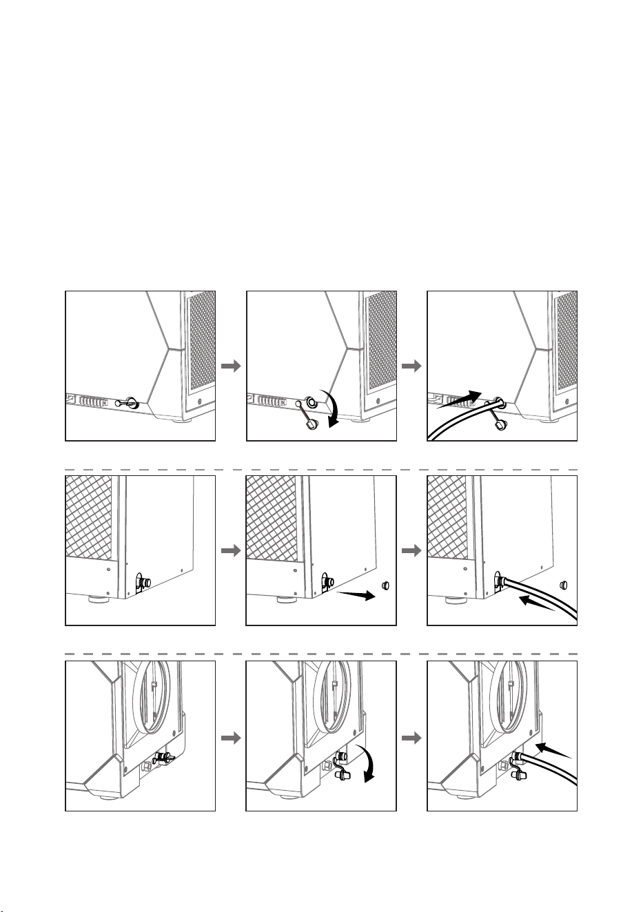
Drainage Function
When using gravity drainage:
1. First, remove the water plug to empty any residual water from the machine.
2. Insert the gravity drainage hose and ensure it is securely fastened before turning on the
dehumidier. Ensure the end of the hose is not higher than the gravity drainage outlet.
3. If the unit begins to leak while elevated and properly leveled, check the drainage outlet
to ensure it is not clogged, and verify that the hose is not bent or kinked.
- 10 -
Drainage Function
When using gravity drainage:
Remove the water plug to release any remaining water from the unit before setup.
Securely attach the gravity drain hose. Ensure the end of the hose is lower than the
drainage outlet before turning on the dehumidier.
If the unit stops running and the operation light blinks slowly with an E4 error on the
display, check the hose for clogs, kinks, or bends. Clear any obstructions—once the
drainage path is clear, the error will reset and the unit will resume normal operation.
If the unit leaks while elevated and level, inspect the drainage outlet for blockages and
verify the hose is properly connected and free of bends or kinks.
Remois XP70
Remois XP125
Remois XP145
- 11 -
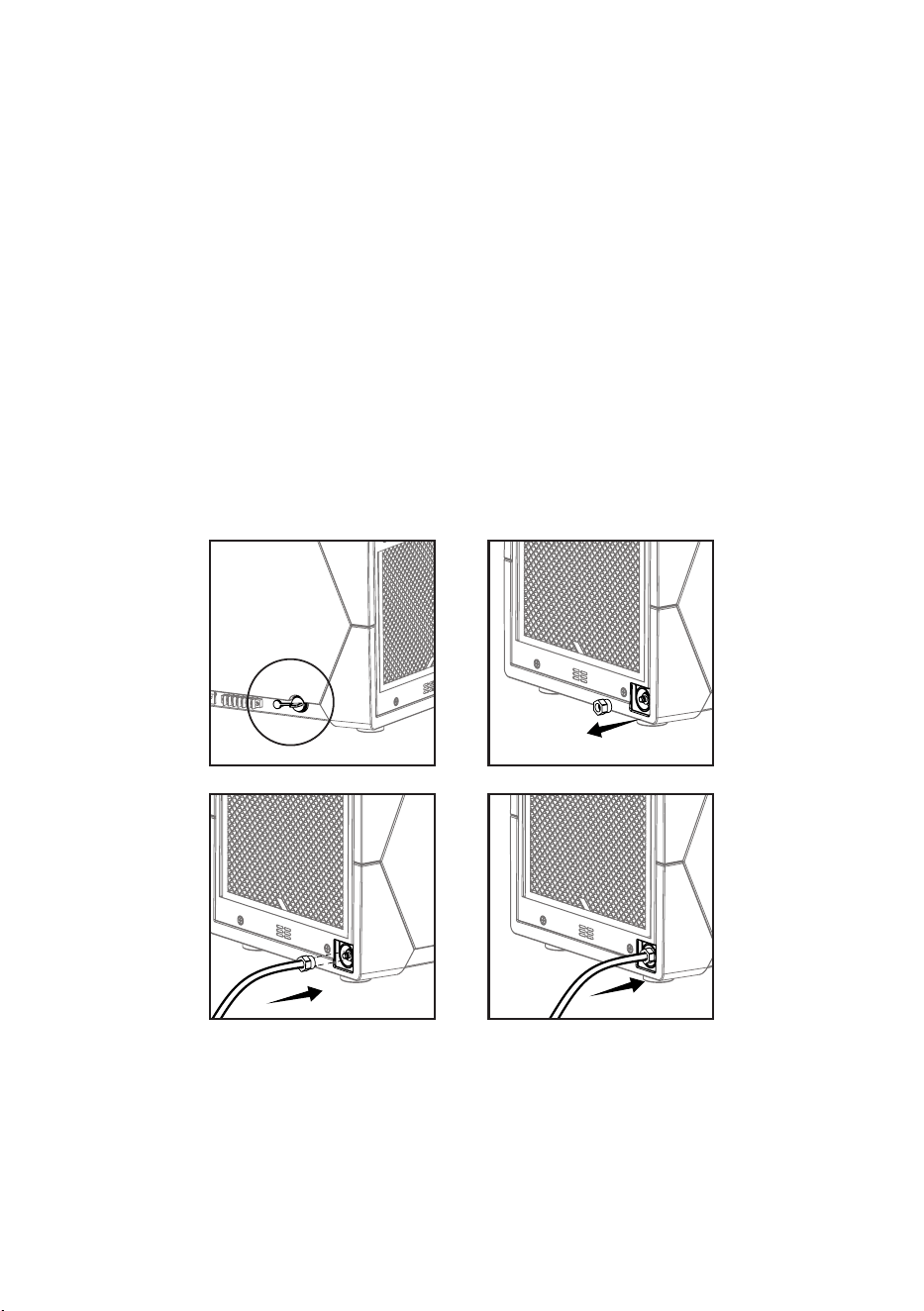
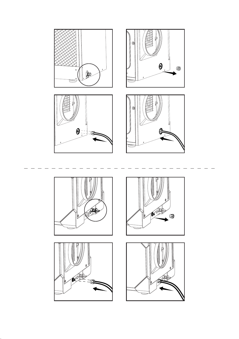
Using the Pump Drainage Function
1. Plug the gravity drainage outlet with the water plug. This is required when using the
pump drainage option.
2. Unscrew the nut on the pump drainage outlet. Pass the drainage hose through the nut,
insert the hose into the outlet, and securely tighten the nut onto the unit’s metal nozzle.
3. Press and hold the DRAIN button for 3 seconds. The unit will beep, and the pump mode
indicator will light up, conrming activation of the water pump function.
4. While in pump mode, briey press the DRAIN button to manually activate a 28-second
drainage cycle.
If an E4 error appears, check if the pump hose is blocked, kinked, or bent. Clear any
obstructions or disable the pump mode. Once the issue is resolved, the E4 error will clear
and the unit will resume normal operation.
Remois XP70
STEP 1 STEP 2
STEP 3 STEP 4
- 12 -
Remois XP125
Remois XP145
STEP 1 STEP 2
STEP 1 STEP 2
STEP 3 STEP 4
STEP 3 STEP 4
- 13 -
MAINTENANCE
Warning:
Always unplug the power before performing any maintenance.
• Cleaning the Machine Body:
Use a soft, damp cloth to clean the exterior of the machine. Do not use any cleaning
agents.
• Coil Maintenance:
Once a year, clean the coils with an approved coil cleaner.
The coil cleaner should be self-cleaning, foaming, and capable of cleaning, such as WEB
®
coil cleaner.
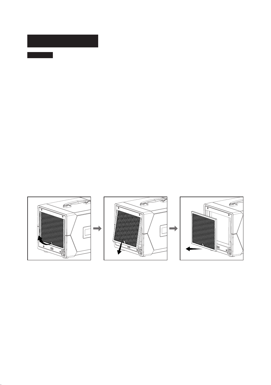
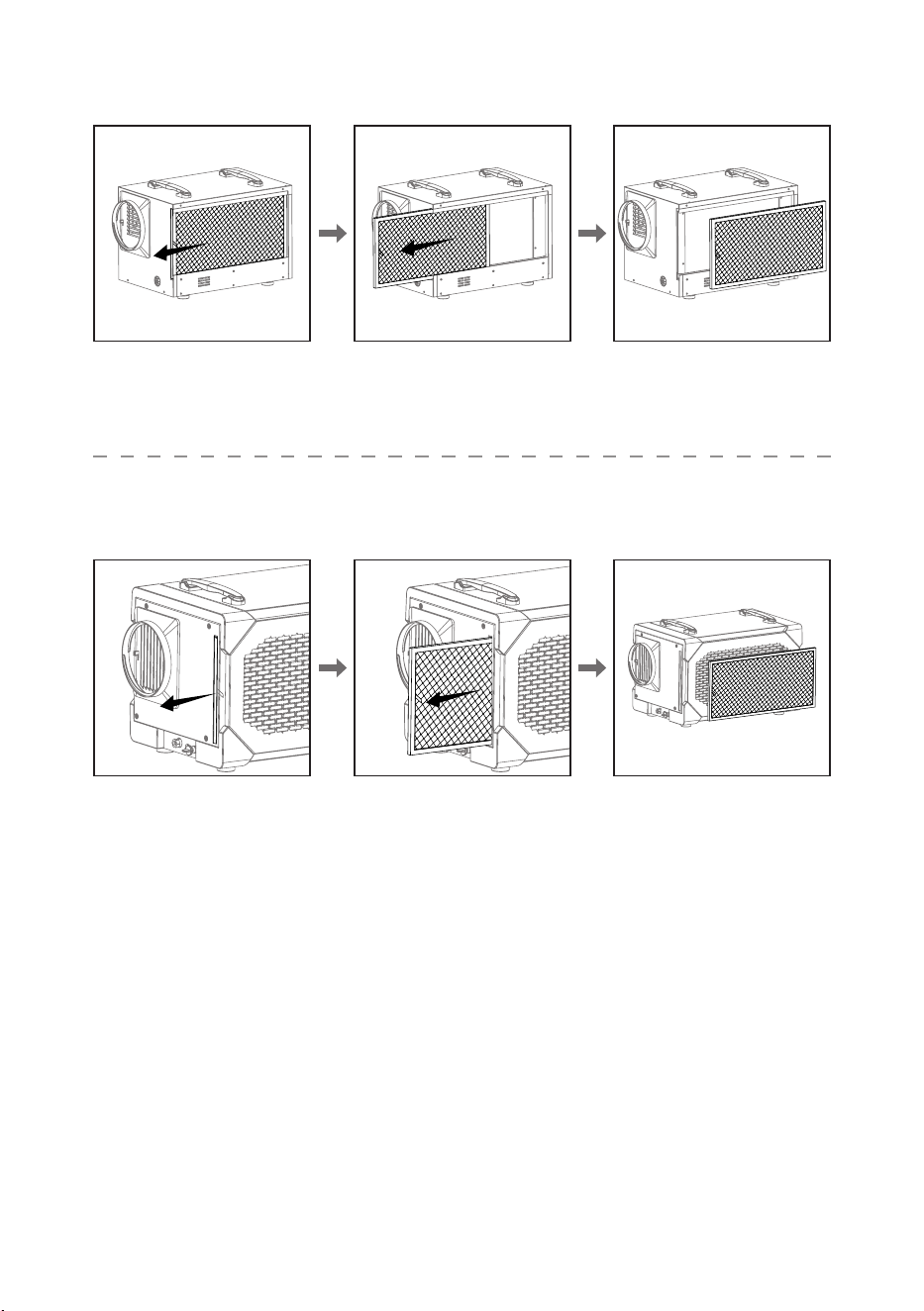
Cleaning the Filter:
1. Remove the lter from the machine.
2. Use a vacuum cleaner or wash it with warm water (do not use any cleaning agents).
3. After cleaning, let it dry in a shaded area before reinstalling it back into the machine.
Remois XP70
- 14 -
Remois XP125
Remois XP145
- 15 -
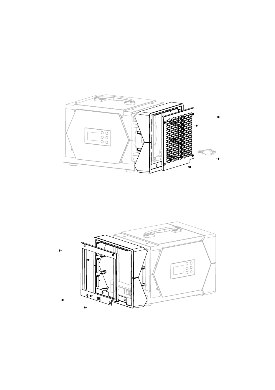
Remois XP70 Water Pump Replacement:
1. Make sure the unit is unplugged, and drain any water from the tank.
2. Remove the lter. (For help, refer to the “Cleaning the Filter” section.)
3. Use a Phillips screwdriver to remove the 4 screws on the air outlet panel. Take o the
panel and any decorative covers.
4. Next, remove the 5 screws on the air intake panel using the same screwdriver. Detach
the intake panel and decorative pieces.
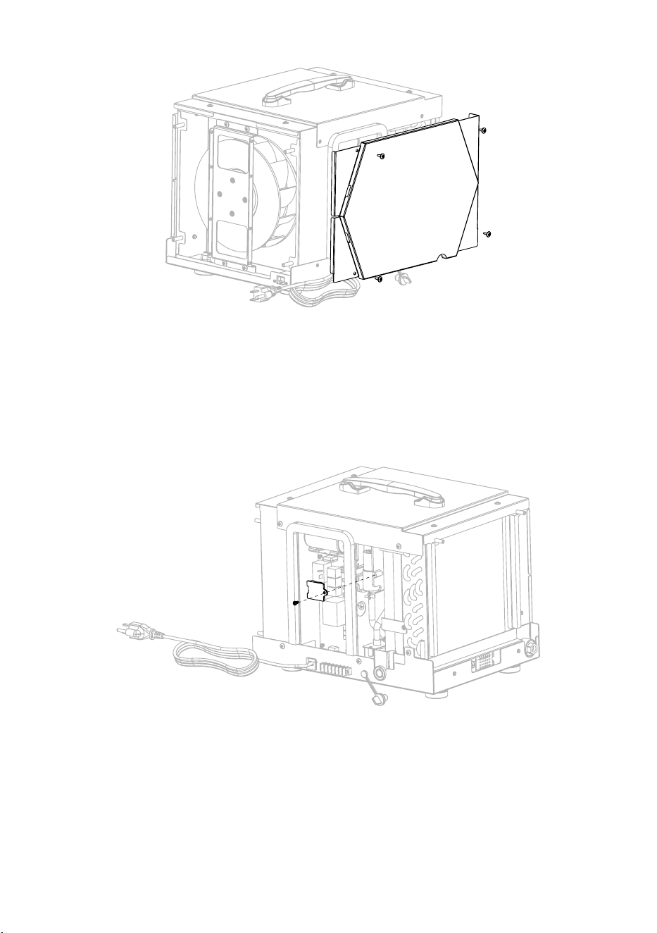
5. Unscrew the 4 screws on the rear panel and remove the rear side panel.
STEP 3
STEP 4
- 16 -
6. Unscrew the single screw holding the water pump mounting bracket and take o the
bracket.
7. Disconnect the water pipe and electrical wires connected to the pump. Carefully remove
the old water pump.
8. Install the new water pump by reversing the steps above, connect the wires and pipe,
secure the pump with the bracket, and reattach all panels.
STEP 5
STEP 6
- 17 -
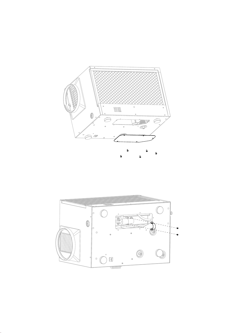
Remois XP125 Water Pump Replacement:
1. Drain the water from the dehumidier and unplug the power.
2. Use a Phillips screwdriver to unscrew the 5 screws on the bottom cover panel and
remove the bottom cover.
3. Use a Phillips screwdriver to unscrew the 2 screws on the water pump clamp.
4. Disconnect the water pipe and the wiring from the water pump to remove the pump.
5. Install the new water pump following the above steps.
STEP 2
STEP 3
- 18 -
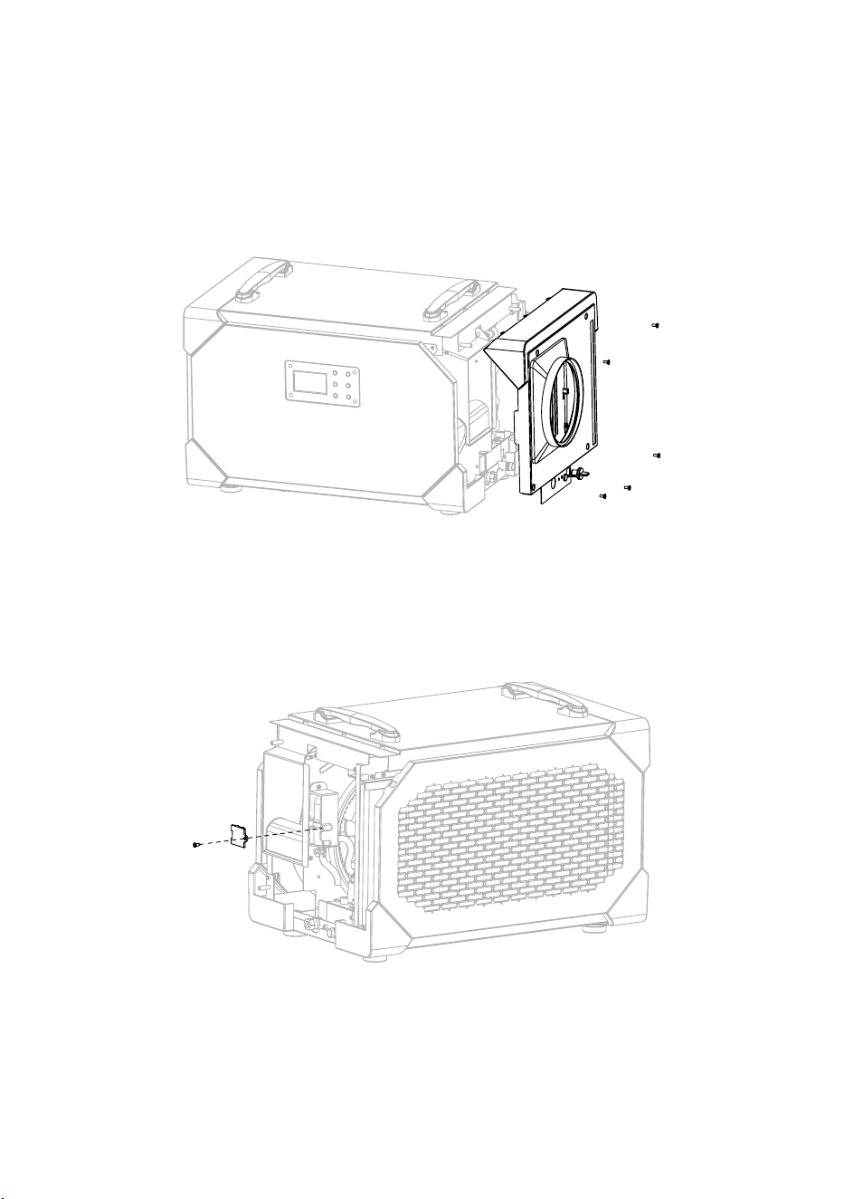
Remois XP145 Water Pump Replacement:
1. Drain the water from the dehumidier and unplug the power and water plug.
2. Use a Phillips screwdriver to unscrew the 5 screws on the air outlet panel and remove
the air outlet panel assembly.
3. Use a cross screwdriver to unscrew the 1 screw on the water pump mounting bracket
and remove the water pump bracket.
4. Disconnect the water pipe and wiring from the water pump to remove it.
5. Install the new water pump following the above steps.
STEP 2
STEP 3

- 19 -
Dehumidier Storage:
If the device will be stored for an extended period, follow these steps:
1. Turn o the machine and allow it to dry.
2. Coil the power cord and store the drainage hose.
3. Place the dehumidier in a clean, dry location.
ENERGY SAVING TIPS
1. Adjust the humidity setting to the highest comfortable level to reduce the amount of
time the dehumidier runs. If it feels humid or “musty”, lower the humidity setting. To save
energy, turn o the dehumidier when you open the windows, just as you would turn o
the air conditioner.
2. If you’re going to be away from home for an extended period of time in the summer,
set the relative humidity to 55% and set the thermostat to the highest temperature you’re
comfortable with in cooling mode. This will keep humidity at a manageable level while
minimizing cooling energy consumption.
OPTIONAL REMOTE CONTROLLER
This dehumidier supports remote control through a dedicated external controller,
connected to the dehumidier via a network cable, enabling you to manage the unit
remotely.
The remote controller is especially useful when the dehumidier is located in a hard-to-
access area, allowing convenient monitoring.
- 20 -
A1-A6 FUNCTIONS
This model is equipped with A1-A6 external functions, providing enhanced versatility.
Below are the terminal function details:
• Terminal Function Version:
A1 - NO:
Normally Open
A2 - COM:
Common port
A3 - ON-D:
External input (24 V AC/DC)
A4 - COM:
External input (24 V AC/DC)
A5 - FLOAT:
External low voltage float switch
or water sensor (use normally
open switch)
A6 - FLOAT:
External low voltage float switch
or water sensor (use normally
open switch)
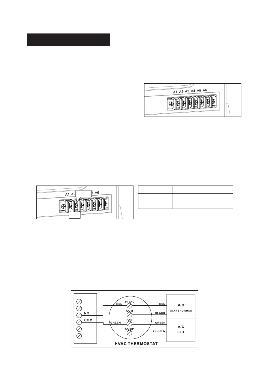
• Auxiliary Relay Operation:
For coordinated fan operation with the central heating/cooling system, the UNIT A1-A2
features a relay. The COM and NO relay terminals operate as follows:
• Common Uses:
(Assuming standard thermostat wiring colors)
Energize the A/C Central Fan During Dehumidifier Fan Operation:
1. Attach a second Green wire to the FAN terminal on the thermostat.
2. Connect the new Green wire to the COM terminal on the UNIT.
3. Run a wire from the Red terminal on the thermostat to the NO (Normally Open) terminal
on the UNIT.
FAN COM to NO
ON CONNEC TED
OFF OPEN
COM
NO
- 21 -
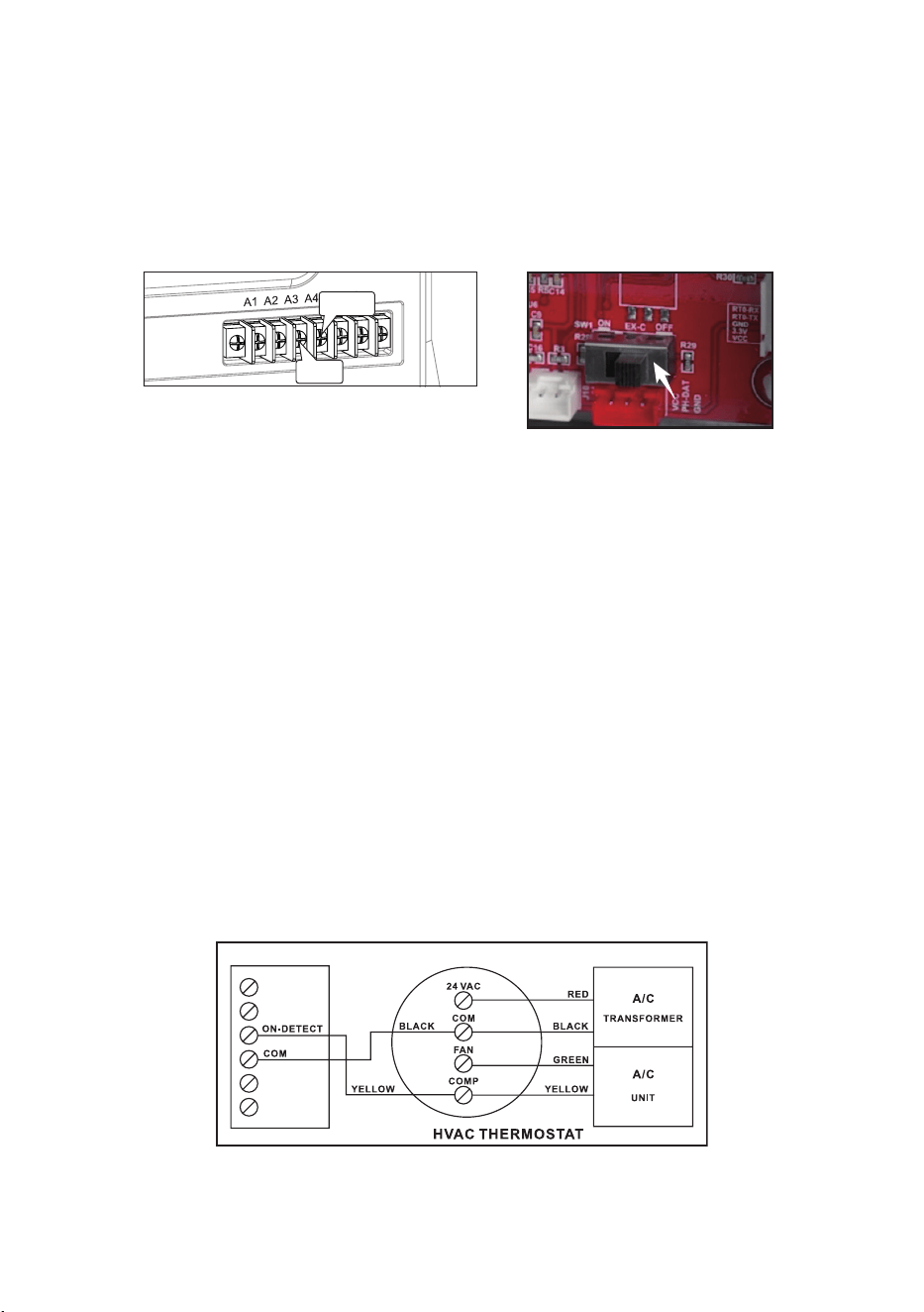
• Dehumidier Lock-On A/C Sensor Feature:
Automatically activate the dehumidifier when the air conditioner runs.
When using A3-A4 function, first to open the machine cover board will switch the
motherboard, to the position of “ON”.
• Activate Dehumidication When the A/C is Running
To enable the Lock-On dehumidifier function, follow these steps using a voltmeter to
ensure correct wiring from the A/C transformer:
1. Connect the common wire from the existing A/C transformer (usually Black) to the “COM”
sensor terminal between “ON-D” on the unit.
●
Tip:
Identify the common wire from the A/C transformer reading 0 volts between it and
the Yellow air conditioning call for cooling wire. An incorrect wire will yield a 20 V to 28 V
reading.
2. Add another Yellow wire to the thermostat Yellow terminal and run it to the “ON-D”
sensor terminal on the unit.
Note:
A5-A6 functions serve as external water pump functions. If these two interfaces
remain continuously connected for 14 seconds, the machine detects an E4 error, causing
the unit to stop. Resolve the E4 error by restarting the unit.
COM
ON-D

- 22 -
Fault
Codes
Problem How to solve
E1
Humidity sensor
malfunction
Replace with a new humidity sensor.
L0
Ambient temperature
≤ 36 °F (2 °C)
When the ambient temperature is detected to be
> 36 °F (2°C), it will automatically restore.
HI
Ambient temperature
≥ 104 °F (39 °C)
When the ambient temperature is <104 °F (39°C),
it will automatically restore.
E3 Defrost Issue
Check for leaks or if the unit is freezing. This may
mean the defrost function isn’t working properly.
E4 Drainage malfunction
Check if the drain is blocked;
Check if the water level switch is stuck.
E5
Coil temperature
sensor failure
Check the system for leaks; if none, test the
sensor for faults.
FUNCTION DESCRIPTION

- 23 -
LIMITED WARRANTY
This limited warranty starts from the date of purchase. CADPXS Solutions Inc. Warrants to the
original purchaser that this CADPXS product is free from manufacturing defects in material or
workmanship for the limited warranty period of:
Six (6) Month parts and labor.
This includes the shipments charges for replacement parts or
unit.
One (1) year parts and labor.
This does not include the shipment charge to send the
defective product back to be repaired or replaced.
Three (3) years parts and labor on Refrigeration System ONLY (Compressor, Condenser,
and evaporator).
Transportation cost, not included.
Five (5) years parts on Refrigeration System ONLY(Compressor, Condenser, and
evaporator).
Transportation cost, not included.
This limited warranty is valid only on products purchased from the manufacturer or CADPXS
authorized dealer and operated, installed, and maintained according to the instructions
included in this user guide or furnished with the product. CADPXS Solutions Inc will not
provide in-home service during or after the warranty period. You may be responsible for the
shipping charge to bring the product to the manufacturer for service.
To receive warranty service, the purchaser must contact CADPXS at (888) 503-0618 or
. A proof of purchase or order number is required to receive warranty
service. During the applicable warranty period, a product will be repaired or replaced at the
sole option of CADPXS.
IMPORTANT NOTICE:
Keep the item’s packaging in case warranty service is required.
In the event that the product is sent for repair without explicit guidance from our customer
service team, CADPXS shall not assume responsibility for any associated repair costs.
LIMITED WARRANTY EXCLUSIONS
This limited warranty covers manufacturing defects in materials or workmanship encountered
in normal household, commercial or noncommercial use of this product and shall not cover the
following:
• Damage occurs in uses for which this product was not intended for.
• Damage caused by unauthorized modication or alteration of the product.
• Cosmetic damage including scratches, dents, chips, and other damage to the product’s
nishes.
• Damage caused by abuse, misuse, pest infestation, accident, re, oods, or other acts of
nature.
• Damage caused by incorrect electrical line current, voltage, uctuations, and surges.
• Damage caused by failure to perform proper maintenance of the product.
The use of this product in SPA or a room with OUTDOOR POOL invalidate or voids limited
warranty.
- 24 -
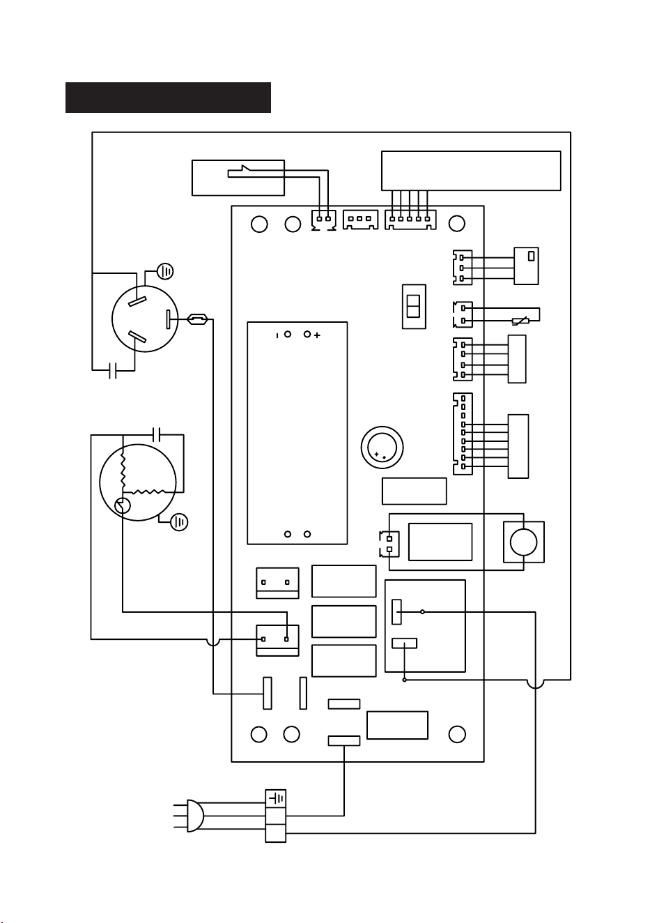
CIRCUIT DIAGRAM
DRAIN
HUMIDITY SENSOR
TEMP.SENSOR
Display
WATERLEVEL
WH
WL
Central control switch
ON EX-C OFF
L
N
NO
COM
N
N
N
IN-FEN
EX-FEN
N
L
PROTECTOR
COMPRESSOR
RC
RC
YEL
YEL
BLU
Network connection
A1
A6
PUMP
BRW
(Not applicable
to Remois XP70)


130131546