01 02 03 04
05 06 07 08 09
01 02 03 04
CELL PHONE SIGNAL BOOSTER
USER MANUAL
SOLVE SIGNAL PROBLEMS
AND IMPROVE QUALITY OF LIFE
CATALOG
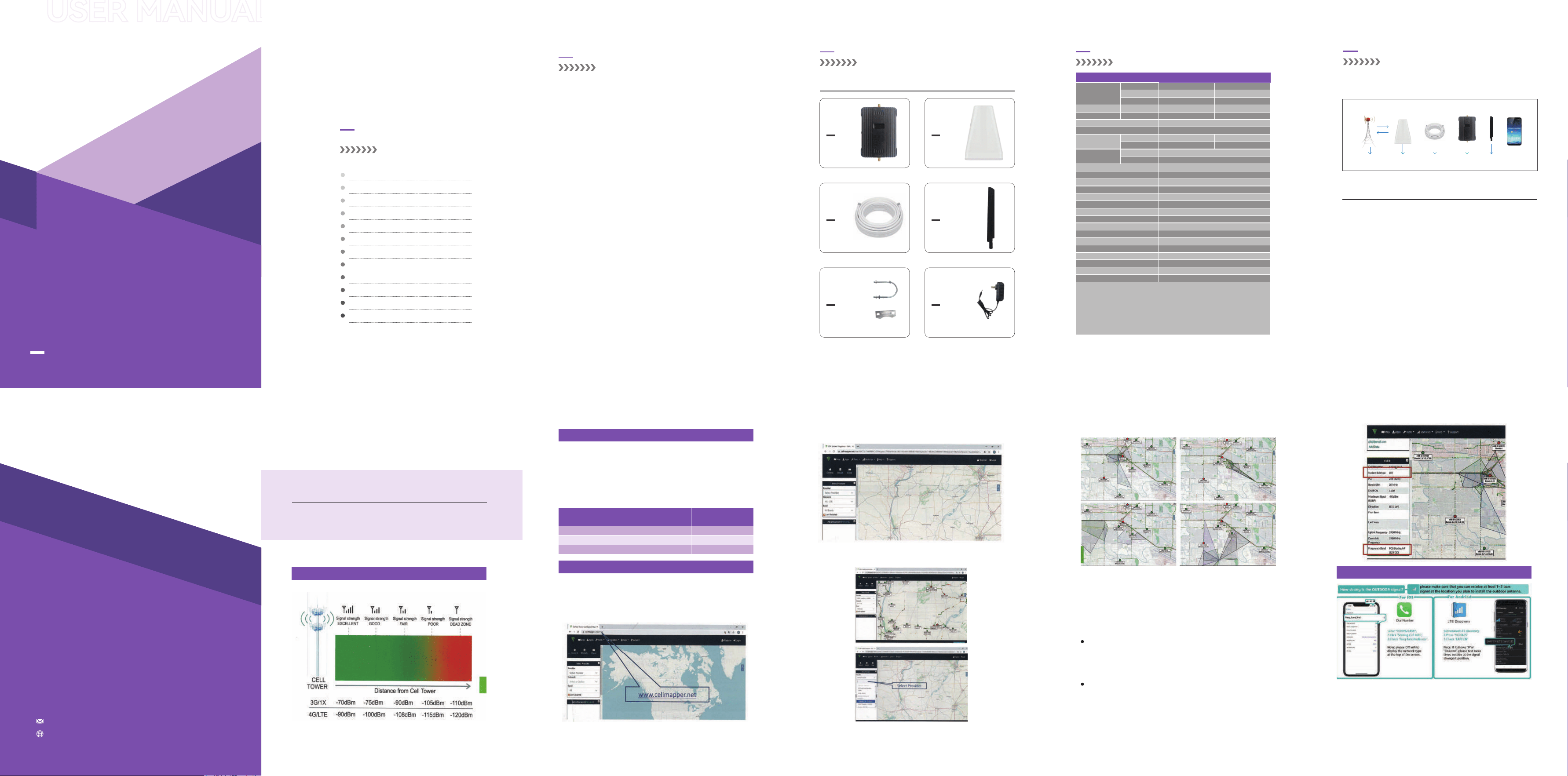
INTRODUCTION
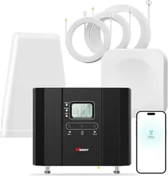
WHAT IS INCLUDED FOR THE KIT
SPECIFICATIONS
HOW IT WORKS
LCD SCREEN INTRODUCTION
HOW TO INSTALL YOUR SIGNAL BOOSTER
INSTALLATION OVERVIEW
1.1 Install Outdoor Antenna
1.2 Install Indoor Antenna
1.3 Install Signal Booster
SAFETY GUIDELINES
PRODUCT WARRANTY
1
2
3
4
10
10
12
15
16
16
19
20
This series booster has been sold oine for a
ve long time and has won unanimous praise
from customers. It can enhance indoor signal,
such as voice, data in home and oce etc, so as
to reduce the problem of call interruption, poor
signal, can help improve voice quality, faster
internet speed and wider coverage.
It also has an advanced set of technical features,
will give you the ultimate control over your signal
quality. Wireless connects multiple devices,
Automatic gain control, this booster has strong
anti-inteerence, low noise characteristic,Works
on bands 5/12/13/17, Suppo all US and Canadi-
an carriers of AT&T, Verizon, T-Mobile, Sprint,
Straight Talk, U.S. Cellular, etc. Cover 2G, 3G, 4G
LTE, and 5G compatible.
INTRODUCTION
WHAT IS INCLUDED FOR THE KIT
Adapter
Outside
antenna
Outside
cable
Indoor
antenna
Indoor
antenna
Accessories
It can cover up to 2500sq.ft coverage.
SPECIFICATIONS
Electrical specication
LTE(A&B)
LTE(C)
CDMA
698~ 716 MHz
776~ 787MHz
824~849 MHz
≤65dB
≤22dBm
Wide Band
≥ 31dB/1dB step
728 ~746 MHz
746 ~757 MHz
869~894MHz
≤65dB
≤10dBm
9KHz~1GHz
1GHz~12.75GHz
9KHz~1GHz
1GHz~12.75GHz
≤ -19dBm
≤ -19dBm
≤ -36dBm
≤ -30dBm
Cell Phone Signal Booster*1
5G Outdoor Log-periodic antenna *1
Indoor whip antenna*1
50ft Cable*1
Kit Including:
≤ -19dBm
≤ -19dBm
Max .Gain
Max .Output Power
Band width
MGC function
Gain Flatness
Noise Figure
VSWR
Group Delay
Frequency stability
LED Alarm
Power LED
ALC LED
Mechanical Specications
I /O Po
Impedance
Operating Temperature
Environment Conditions
Dimensions
Weight
Power Supply
≤8dB
≤6dB
≤2
≤ 1.0μs
≤ 0.01ppm
Standard
Power Indicator
Orange @ ALC 1~5dB, Red @ ALC15dB~20dB,
Standard
SMA-Female
50 ohm
-25ºC~+55ºC
IP40
131*89*22mm/5.16*3.5*0.866in
0.2kg/0.441Lb
Input AC100~240V,output DC5V/2A
Intermodulation
Products
Spurious Emission
Frequency Range
(700+850Mhz)
Uplink Downlink
The coverage area and the strength of the boosted signal are directly related to
two key factors:
Signal strength received by the outdoor unit. So, setting up the outside unit
where the signal is the strongest will provide the best results.
1.
Working Principle:
Outside Signal:
Outdoor Antenna Gain: The gain of outdoor antenna
Outdoor Cable Loss: The loss of the outdoor cable
Booster Gain: The actual working gain of the booster
Indoor Cable Loss: The loss of the indoor cable
Indoor Antenna Gain: The gain of indoor antenna
Receive the signal from the outdoor
base station signal tower
HOW IT WORKS
outside signal
Base Station
outdoor calbe booster indoor antennaoutside antenna
Signal transmission loss and power level
Distance of separation between the outdoor unit and the indoor unit.2.
Please make sure the horizontal distance between outdoor antenna and
indoor antenna is more than 6 meters(20ft);The veical distance between
indoor antenna and outdoor antenna is more than 3 meters(10ft)
3.
Tips:The user guide is focused on:
1. Getting the best outside signal.
2. Keeping the maximum booster gain.
For example:
-65dBm + 6dBi - 5dB + 70dB - 3dB + 6dBi = 9dBm (System Output Power)
Note: FCC regulations limit the amplication of all cell phone boosters in order to
prevent damage to the telecommunications infrastructure. Therefore, the
maximum coverage area of a booster depends on the original power level of the
signal captured by the outdoor unit.
Notice: Not recommended when outdoor signal strength is less than -110dbm
(3G/lx) or -120dBm(4G/LTE). The resulting coverage area of the boosted signal
will be prohibitively small.
Find your cell tower nearby!
There are a variety of resources available online, here is a third pay website
recommended. Use it to locate your nearest cell tower: www.cellmapper.net
Preparation
Coverage area ability
Visit website www.cellmapper.net
Step 1.
Power Level
at the outdoor antenna location
Strong(4~5 bars on the cellphone)
Coverage Area
(sq.ft)
Medium(3~4 bars on the cellphone)
Weak(1~2 bars on the cellphone)
2,500
1,000
300
Select Provider. You will nd the cell tower around your house.
Step 3.
Find your location on the map and zoom in on your area
Step 2.
Click the red or green dot on the map that represents the base station, and the
detailed information of the base station will be displayed.
The rst impoant information, you can see from the above four pictures, the
coverage area (shaded pa) of each base station is dierent. You have to nd
a base station with signal coverage to your house, or the coverage direction is
facing you, and the coverage area is closest to you.
The second impoant information, you can scroll the information content on
the right to nd the specic carrier information of this base station, including
the communication standard and frequency band. Please reference the right
picture, "LTE〃 and "B2 FDD'(Band 2, FDD).
Find your cell tower
Step 4.
How to choose the right booster before purchase?
For iPhone - Please dial *3001#12345#* → Press call button
→ Click
'Seing Cell Info' → Check 'Freq Band Indicator'.
For Android - Please download 'LTE Discove' APP
→Click
‘SIGNALS’ → Check ‘EARFCN’.
admin@szzj-tech.com
www.szzjtechnology.com
www.szzjtechnology.com
12 13 14 15
17 18 19 2016
10 11
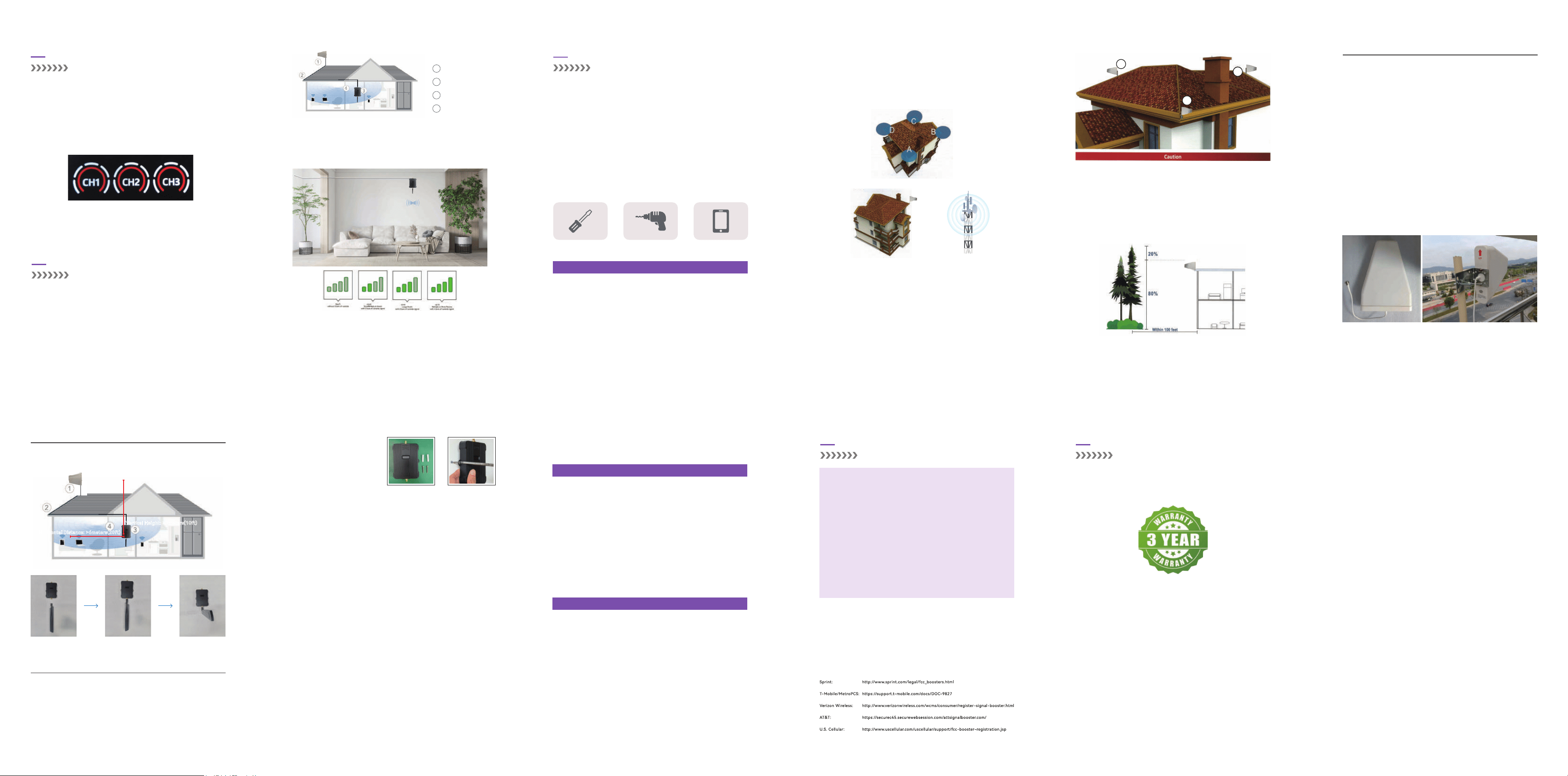
LCD SCREEN INTRODUCTION
The strength of the outdoor input signal
①.Ve Strong(it will have 5 bars, the red bar also lights up )
②.Strong(it will have 5 bars ),
③.Medium(about 3~4 bars ),
④.Weak(only have 1-2 bars ),
HOW TO INSTALL YOUR SIGNAL BOOSTER
This user manual will help you properly install your signal booster kit.
lt is impoant to read through all of the installation steps before installing your
equipment.
Thoroughly read through the instructions, visualize where all the equipment will
need to be installed and do a soft installation by placing the devices where they
need to be before mounting any equipment.
Note: The booster requires 1-2bars reliable signal outdoor, we recommend you
to test your signals outdoor on your mobile phone before purchasing.
Here are the eects of dierent signals for your reference.
1
Outdoor antenna
2
Cable
3
Indoor Antenna
4
Booster
2500sq.ft1000sq.ft300sq.ft
There are tools required before installation as follows FYI:
Find the outside area with the strongest signal.
Step 1.
Install the outside antenna on the roof to obtain the strongest downlink
signal from the local cellular towers. It should also be as far away as
possible from where you plan to place the indoor antenna.
Step 2.
Mount the boost; connect the cables from the outdoor antenna and
indoor antenna at the designated pos, or place the Flare on a table or
desktop, center of the area where signal is needed.
Step 4.
Connect the booster to an AC power source.
(make sure all the cables are connected tightly before applying power)
Step 5.
Install the indoor antennas where you want to improve the signal level.
Step 3.
Tools Required
Phillips Screwdriver Drill Mobile Phone
INSTALLATION OVERVIEW
Note:This is the most critical step and will determine the overall peormance of
the booster system.
Select the Location for the Outside Unit
Step 1.
We STRONGLY recommend doing a test installation before nalizing the installation.
Doing a test installation of your cell phone booster ensures that you will get the optimal
peormance from your system.
Test Installation
Four corner of the building are the most ideal position
choose the one near your cell tower
In most situations, the strongest signal is found about 25 feet above the ground
on the side of your home facing the nearest cell tower.
In addition to the four corners of the building, the chimney and the pole above
the roof can also be selected, As long as the installation distance between in
door and outdoor antennas is maintained enough, satisfacto results can also
be achieved.
Use one of the three options to mount the outside antenna on your roof on the
side of the house with the strongest signal.
The height of the outside antenna should never exceed the highest point of your
house. This is a precaution against damage and safety concerns caused by
lightning strikes to the outside unit.
Generally, the strongest signal will be located on the side of your home facing
the nearest cell tower. Keep in mind, the signal strength at ground level may be
dierent from the signal strength at or above the roof line due to obstructions
(trees, other buildings, etc.) that block the incoming signal.
1.
The most ideal installation position is the corner of the building, choose the
one facing your cell tower.
2.
Temporarily Mount the Outside Antenna
Step 2.
A Outdoor antenna must be installed over the roof line.
Trees will greatly attenuate wireless signals. If there are tall trees within 100 feet
of the house. At the same time you can not nd a stable signal above 3 bars, the
outdoor antenna needs to be erected 60%(at least) to 80% (best) of the tree
height, Never exceed the trees!
But according to FCC regulations, outdoor antenna height cannot exceed 30
feet.
At the same time, if the antenna exceeds the roof, please pay attention to
lightning protection measures.
B
C
A
Installation Method 1:
Determine the installation position of the Yagi antenna according to the range to be
covered, the antenna is suitable for more than 3 meters from the ground, eectively
avoiding ground objects and obstructions, and directed to the location of the base
station, the higher it is installed, the better the eect
1.
Conrm the location, you need to x the antenna with a U-shaped bolt on the
installation pole, usually the antenna's small teeth face upward, in order to play the
reception eect
2.
Connect antenna to one end of the provided cable and tighten the connection, Run
the cable along route to planned location of your booster
3.
1.1 Install Outdoor Antenna
Testing the signal 3 times in the desired location before installing
the outdoor antenna will help ensure the clearest and most stable
signal for phone calls and data transmission.
IMPORTANT:
Please directly connect the indoor antenna to the indoor po of the signalboost-
er,please refer to the following diagram for installation.
1.2 Install Indoor Antenna
Veical Height: >3meters(10ft)
Horizontal Distance: >6meters(20ft)
1.3 Install your signal booster
Place the booster in a central location where signal is needed and at least 50ft.
from the outdoor antenna location. And the signal booster should be mounted in
an easily accessible area so it's easy to peorm general maintenance. The
optimal area would be on a wall located near a power outlet. Mount the booster
with the included screws as shown in the gure below.
step1 step2 step3
FCC Ceication:
Power listed is conducted at antenna terminals. The antennas used with the
signal booster must be installed to provide a separation distance of at least
20cm from all persons. Users and installers must be provided with the
antenna kitting and installation and operating instructions and conditions
for satisfying RF exposure and Section 20.21(a) compliance.
This Wideband Consumer Signal Booster is authorized only for operation by
and marketing to members of the general public for their personal use in
accordance with the requirements of Sections 20.21(a)(7) and 20.21(g). This
device is a Wideband Fixed Consumer Signal Booster approved for
operating with the coverage/seer antenna installed at a xed location
inside a building.
The booster will be installed as below steps:
Note:
Connect the cable of the indoor antenna to the po on the side of the booster
silk-printed INDOOR
3.
Route the cable from the outside antenna inside and connect it to the po on
the booster silk-printed OUTDOOR
4.
Connect the power adapter cord to the signal booster and plug into the power
outlet. The LCD Screen will light and functioning properly
5.
Do NOT connect the power adapter to the Signal Booster until you have
connected both the Inside and Outside Antennas.
1.
The booster case may become warm during operation, this is normal, please
don’t wor.
2.
Secure both sides of the unit with
screws and mount it on the wall.
1.
To uphold network protection standards and ensure compliance, all active
cellular devices must maintain a separation distance of at least six feet between
the inside unit antenna and outside unit antenna and at least four feet of
separation distance from the inside unit. Use only the power supply provided in
this package. Use of a non-Amsignalbars product or accesso may result in
damage to the equipment or comp orients of the equipment. The in side unit is
designed for use in an indoor, temperature-controlled environment (less than
100 degrees Fahrenheit). It is not intended for use in attics or similar locations
where temperatures may be in excess of that range.
RF Safety Warning: Any antenna used with this device must be located at least
8 inches from all persons.
How to choose the right booster before purchase?
Safety Guidelines
Check incoming signal level at outdoor antenna position.
Usage of a booster is not recommend when the outdoor signal is than
-110dbm(3G) or-120dBm(4G).
Which means Please make sure that you can receive at least 1-2bars
signal at the location you plan to install the outdoor antenna.
Step 2.
Check band number. Make sure your band number belongs to one of the
following: band 5/12/13/17. If not, then this booster is not the best
choice for you.
Step 1.
This device complies with Pa 15 of FCC rules. Operation is subject to two
conditions: (1) This device may not cause harmful inteerence, and (2) this
device must accept any inteerence received, including inteerence that may
cause undesired operation. Changes or modications not expressly approved
by Amsignalbars could void the authority to operate this equipment.
FOR MORE INFORMATION ON REGISTERING YOUR SIGNAL BOOSTER WITH
YOUR WIRELESS PROVIDER, PLEASE SEE BELOW:
BEFORE USE, you MUST REGISTER THIS DEVICE with your wireless
provider and have your provider's consent. Most wireless providers
consent to the use of signal boosters. Some providers may not consent to
the use of this device on their network. If you are unsure, contact your
provider.
In Canada, BEFORE USE you must meet all requirements set out in ISED
CPC-2-1-05. You MUST operate this device with approved antennas and
cables as specied by the manufacturer. Antennas MUST be installed at
least 20 cm (8 inches) from (i.e., MUST NOT be installed within 20 cm of)
any person.
You MUST cease operating this device immediately if requested by the
FCC (or ISED in Canada) or licensed wireless seice provider.
WARNING. E911 location information may not be provided or may be
inaccurate for calls seed by using this device.
This is a CONSUMER device
SAFETY GUIDELINES
IC Ceication:
The signal booster is compliance with the requirements of the standards
ICES-003 applied
PRODUCT WARRANTY
30-Day Money-Back: All boosters are protected by a 30-day money- back
guarantee. If for any reason the peormance of any product is not acceptable, the
product may be returned to the reseller with a dated proof of purchase.
3-Year Warranty boosters and kits are warranted for 3 years. Products returned by
customers must be in their original, un-modied condition, shipped in the original
or protective packaging with proof-of-purchase documentation enclosed, and a
Return Merchandise Authorization (RMA) number printed clearly on the outside of
the shipping container.
PRODUCT WARRANTY
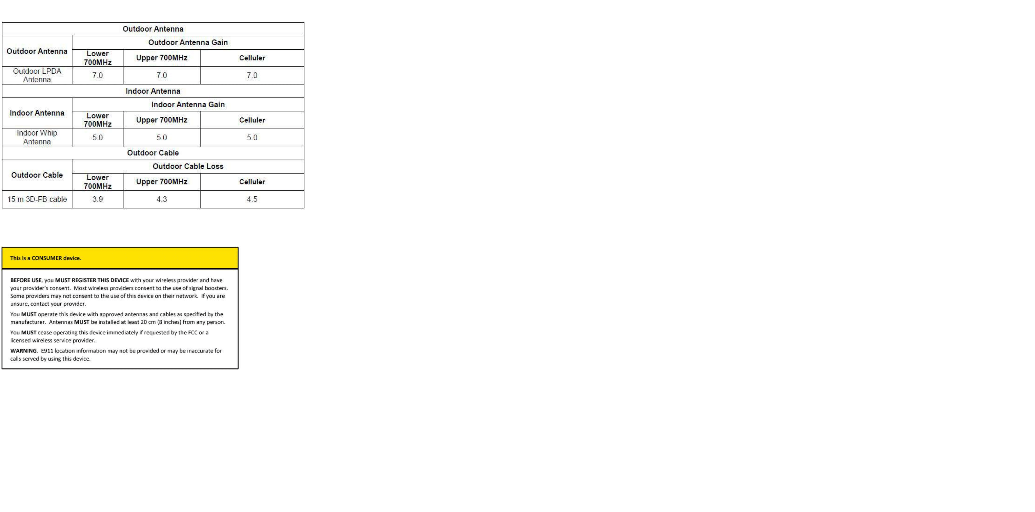
Complete list of authorized antennas, cables, and cable loss:
FCC Warning
This device complies with part 15 of the FCC rules. Operation is subject to the following two conditions: (1) this device may
not cause harmful interference, and (2) this device must accept any inte rference received, including interference that may
cause undesired operation.
Changes or modifications not expressly approved by the party responsible for compliance could void the user's authority to
operate the equipment.
NOTE: This equipment has been tested and found to comply with the limits for a Class B digital device, pursuant to part 15
of the FCC Rules. These limits are designed to provide reasonable protection against harmful interference in a residential
installation. This equipment generates uses and can radiate radio frequency energy and, if not installed and used in
accordance with the instructions, may cause harmful interference to radio communications. However, there is no guarantee
that interference will not occur in a particular installation. If this equipment does cause harmful interferenceto radio or
television reception, which can be determined by turning the equipment off and on, the user is encouraged to try to correct
the interference by one or more of the following measures:
·
Reorient or relocate the receiving antenna.
· Increase the separation between the equipment and receiver.
· Connect the equipment into an outlet on a circuit different from that to which the receiver is connected.
· Consult the dealer or an experienced radio/TV technician for help.
Radiation Exposure Statement
This equipment complies with FCC radiation exposure limits set forth for an uncontrolled environment. This equipment
should be installed and operated with minimum distance 20cm between the radiator and your body.
Warning label requirements
1) Warning: The Inside Antennas for fixed installations must have 6 feet of
separation distance from all active users.
2) Warning: The Outdoor Antennas/Indoor Antennas for fixed installations
must be installed no higher than 10 meters above ground.
3) Warning:Unauthorized antennas, cables, and/or coupling devices are
prohibited by FCC rules.Please contact FCC for Details:1-888-CALL-FF.
4) Warning:The antenna,cable,and other accessories of the booster kits shall
not be modified without the approval of the party responsible,others it shall be
deemed invalid.