
9
1
2
7
(2x)
11
(12x)
33
35
36
37
38
40
26
69
43
34
6
71
16
15
18
15
17
(3x)
19
(2x)
14
(3x)
13
(3x)
12
10
(2x)
76
77
(2x)
79
80
20
21
22
23
25
29
24
(2x)
27
87
88
28
72
57
56
55
54
53
52
51
48
44
78
30
31
68
65
70
62
63
64
66
61
60
59
58
32
42
41
47
46
45
49
50
(4x)
73
74
75
86
81
(3x)
5
4
(4x)
8
(2x)
41
42
101
30
31
104
1 2 3 4
5 6 71
90
13 14 15 16
17 18 82
99
10 11 12 16 19 20
76 77 86 87 88
103
7 8
9
93
79 80
81
105
21 24 25
27 28
100
33 34 35
36 39
98
60 61 62
68 70
91
51 52 54
58 59
96
49 50 53
63 64
102
55 56
57
97
26 43 44 45 46
47 48 66 67
95
37 38
40
92
22 23
29 69
94
39
3
(2x)
Note: Return the tool
to a Milwaukee
Authorized Repair
Center for QR code
(86) replacement.
MILWAUKEE TOOL
l
www.milwaukeetool.com
13135 W. LISBON RD., BROOKFIELD, WI 53005
Drwg. 1
BULLETIN NO.
PN0008601
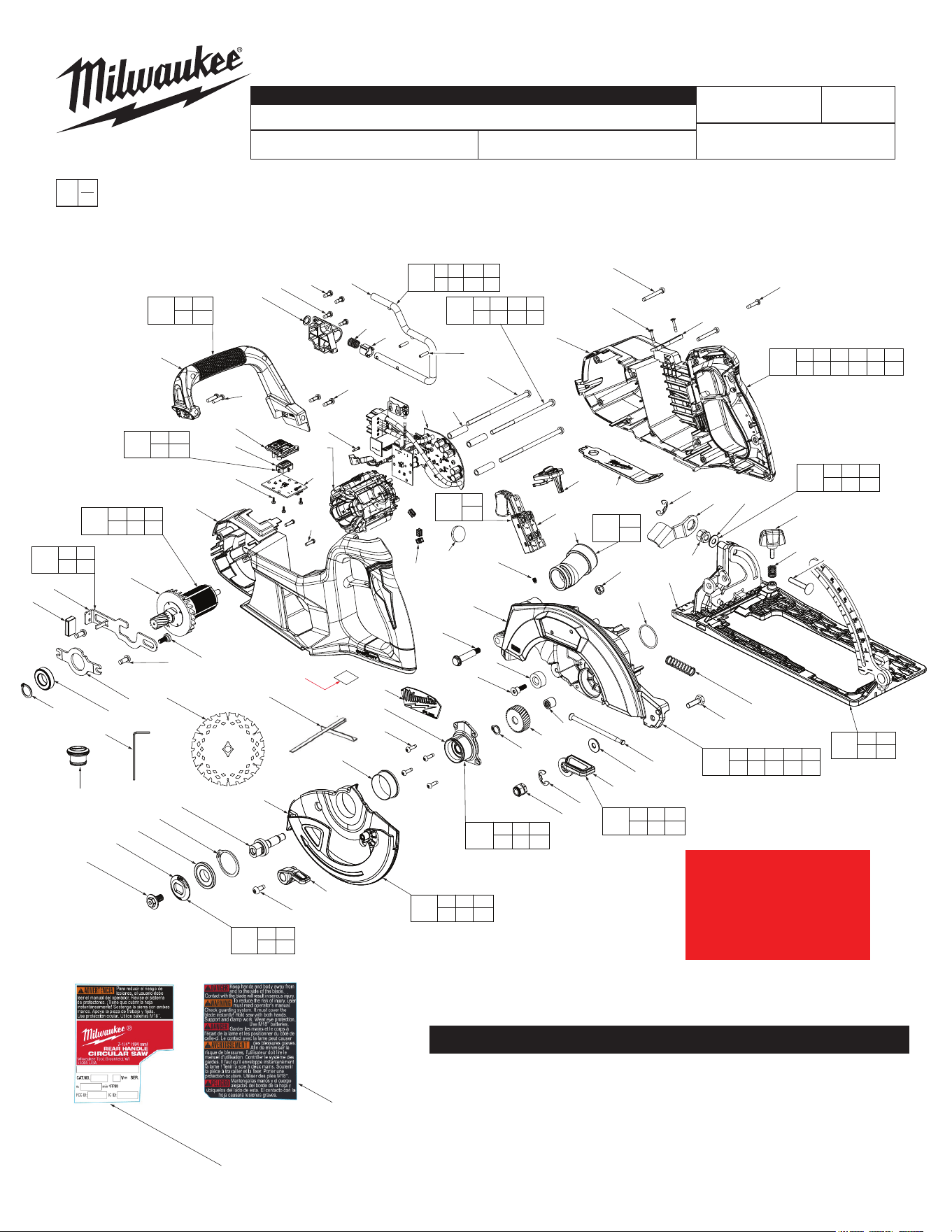
SERVICE PARTS LIST
CATALOG NO. 2931-20
REVISED BULLETIN
SPECIFY CATALOG NO. AND SERIAL NO. WHEN ORDERING PARTS
M18 FUEL™ One-Key™ Rear Handle Circular Saw (7-1/4")
SERIAL NO.
DATE
Feb. 2026
WIRING INSTRUCTION
R55A
See Page 5
0
00
EXAMPLE:
Component Parts (Small #)
Are Included When Ordering
The Assembly (Large #).
DETAILED SERVICE BILL OF MATERIAL (BOM) ON PAGE 2
FIG. PART NO. DESCRIPTION OF PART NO. REQ.
1 --------------- Rafter Hook (1)
2 --------------- Detent Sleeve (1)
3 ---------------
Spring Pin
(2)
4 05-88-1220 M4 x 10mm Steel PH Torx T-20 Screw (4)
5 --------------- Rafter Hook Base Plate (1)
6 --------------- Detent Spring (1)
7 05-88-5375 M4 x 13.5mm PH Torx T-20 Screw (2)
8 05-74-0986 M4 Screw (2)
9 --------------- Secondary Handle (1)
10 05-74-0023 M4 x 32mm PH Torx T-20 Screw (2)
11 --------------- #6-19 Torx T-15 Screw (12)
12 --------------- Handle Cover (1)
13 --------------- M5 x 0.8 PH Torx T-25 Screw (3)
14 --------------- Spacer, Heat Sink (3)
15 --------------- PCB Assembly (1)
16 45-88-0229 M2 x 0.635 PH Torx T-6 Screw (1)
17 --------------- Isolator (3)
18 --------------- Stator (1)
19 05-78-1010 M3.5 x 0.6 PH Torx T-10 Screw (2)
20 --------------- Handle Support (1)
21 --------------- Rotor (1)
22 --------------- Spindle Lock (1)
23 --------------- Spindle Lock Lever Cover (1)
24 05-74-1030 M5 x 0.8 PH Torx T-25 Screw (2)
25 --------------- Retaining Plate (1)
26 02-02-0137 O-Ring (1)
27 --------------- Ball Bearing (1)
28 --------------- C-Ring (1)
29 45-04-1224 Arbor Plate Screw (1)
30 --------------- Switch (1)
31 --------------- Lock Slider (1)
32 45-88-9320 Blade Bolt Wrench (1)
33 --------------- Bowed E-Ring (1)
34 --------------- Bevel Adjust Level (1)
35 --------------- Hexagon Nut (1)
36 --------------- Washer, SPCC (1)
37 43-30-5581 Rip Fence Knob (1)
38 23-52-0100 Spring (1)
39 --------------- M6 x 1 Bevel Screw (1)
40 --------------- Shoe Assembly (1)
41 --------------- M4 Set Screw for Framer (1)
42 --------------- Dust Collection Outlet Nozzle (1)
43 06-04-8412 Hexagon Nut M6 x 1 (1)
44 --------------- Upper Guard Gearcase (1)
45 06-14-0036 Pivot Shoulder Bolt (1)
46 42-38-0224 Rubber Bumper (1)
47 45-04-0485 M4 x 19mm PH Torx T-20 Screw (1)
48 --------------- Logo Plate w/ Adhesive (1)
49 --------------- Output Hub (1)
50 06-82-5285 #6-32 PH Torx T-15 Screw (4)
51 --------------- Plastic Sleeve Ring (1)
52 --------------- Lower Guard (1)
53 --------------- Output Shaft (1)
54 34-60-0177 Retaining Ring (1)
55 --------------- Inner Blade Flange (1)
56 --------------- Outer Blade Flange (1)
57 --------------- Blade Bolt (1)
58 06-82-5314 #10-24 PH Torx T-25 Taptite Screw (1)
59 --------------- Lower Guard Lever (1)
60 --------------- Hexagon Nut (1)
61 --------------- E-Ring (1)
62 --------------- Depth Adjust Lever (1)
63 --------------- Snap Ring (1)
64 --------------- Gear – Crowning Version (1)
65 49-68-5212 Spring (1)
66 --------------- Needle Bearing (1)
68 05-85-0056 M6 x 19mm Hex Head Screw (1)
69 --------------- Spindle Lock Spring (1)
70 --------------- Washer (1)
71 --------------- Flat Washer Steel (1)
72 06-67-4624 Dust Port Rubber Plug (1)
73 45-96-6334 M2 Hex Wrench (1)
74 48-40-0740 Blade (1)
SERVICE BILL OF MATERIAL (BOM) LISTING
75 49-22-1005 Rip Fence (1)
76 31-21-5540 Battery Cover (1)
77 06-82-0248 M3 x 1.058 FH Phillips Screw (2)
78 --------------- Coin Cell Battery (CR2032) (1)
- See local hardware store
79 --------------- VacLink ONE-KEY UI Panel (1)
80 --------------- Rubber – VacLink Button (1)
81 05-88-0106 M2 x 0.89 PT Screw (3)
86 10-15-9730 ID Label (1)
87 12-20-0460 Service Nameplate (1)
88 10-22-0000 Warning Label (1)
90 14-36-5887 Rafter Hook Assembly (1)
91 14-46-1233 Depth Adjust Kit (1)
92 14-74-5227 Shoe Kit (1)
93 14-46-1213 Secondary Handle Kit (1)
94 14-46-9841 Spindle Lock Kit (1)
95 14-32-8334 Upper Guard Assembly (1)
96 14-32-8348 Lower Guard Assembly (1)
97 43-34-6229 Blade Nut & Flange Kit (1)
98 14-46-1219 Bevel Adjustment Kit (1)
99 14-20-0000 Electronics Assembly (1)
100 14-73-0001 Inner Rotor Assembly (1)
101 14-46-1228 Dust Kit (1)
102 14-73-9876 Output Shaft Assembly (1)
103 14-34-0000 Handle Cover Kit (1)
104 23-66-0120 Switch Kit (1)
105 14-06-5078 UI Service Kit (1)
FIG. PART NO. DESCRIPTION OF PART NO. REQ.
FIG. NOTES
86-88 A clean, dry surface is essential for proper performance for
any adhesive system. The area intended for application of
any adhesive label or nameplate must be prepared by
cleaning with isopropyl alcohol. The solvent is to be applied
with a clean, lint free applicator and the surface allowed to
dry before applying the label or nameplate.
SEAT TORQUE
FIG. PART NO. WHERE USED (kgf-cm) (lb-in)
4 05-88-1220 Rafter Hook Base Plate (5) 12 ± 1 10 ± 1
7 05-88-5375 Secondary Handle (9) 12 ± 1 10 ± 1
8 05-74-0986 Secondary Handle (9) 11 ± 1 9.5 ± 1
10 05-74-0023 Handle Cover (12) 15 ± 1 13 ± 1
NOTE – Screw driver speed is lower than 800RPM
11 06-82-7470 Handle Cover (12) 13 ± 2 11 ± 1
13 --------------- Stator (18) 18 ± 2 16 ± 1
16 45-88-0229 Stator (18) 2.5 ± 0.2 2.2 ± 0.2
19 05-78-1010 Handle Support (20) 10 ± 1 9 ± 1
24 05-74-1030 Rotor Retaining Plate (25) 30 ± 3 26 ± 3
29 45-04-1224 Spindle Lock (22) 21 ± 2 18 ± 2
35 --------------- Shoe Assembly (40) –
Bevel Adjustment
22 ± 1 19 ± 1
41 05-74-0143 Upper Guard Gearcase (44) 15 ± 1 13 ± 1
NOTE – Use corner screwdriver, only travel 4 rotations
4 5 06-14-0036 Upper Guard Gearcase (44) 22 ± 2 19 ± 2
47 45-04-0485 Upper Guard Gearcase (44) 35 ± 3 30 ± 3
50 06-82-5285 Output Hub (49) 17 ± 3 15 ± 3
57 --------------- Output Shaft (53) 10 ± 1 9 ± 1
5 8 06-82-5314 Lower Guard(52) 35 ± 3 30 ± 3
60 --------------- Upper Guard Gearcase (44) 40 ± 4 35 ± 3
77 --------------- Battery Cover (76) 4.5 ± 0.3 3.9 ± 0.3
81 05-88-0106 PCB Assembly (15) 2.4 ± 0.3 2.1 ± 0.3
SCREW TORQUE SPECIFICATIONS
2
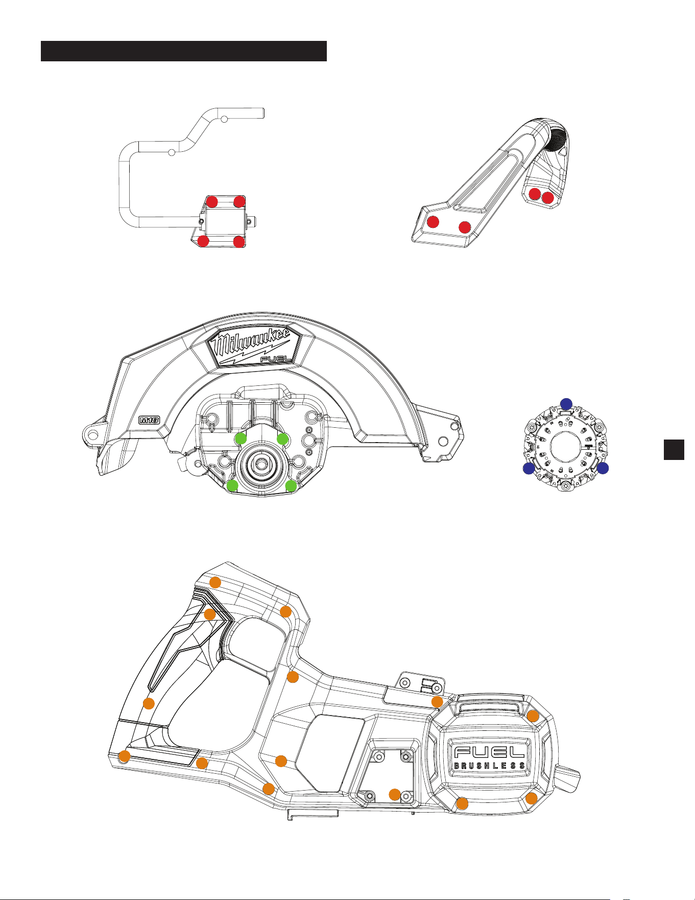
Stator (18)
Secondary Handle (9)
Rafter Hook (1)
Upper Guard Gearcase (44)
Handle Cover (12)
1
2
3
4
5
6
7
8
9
10
11
12
14
13
1
2
3
1
2
3
4
1
2
3
4
1
2
3
4
HOUSING SCREWS - FASTENING ORDER
3
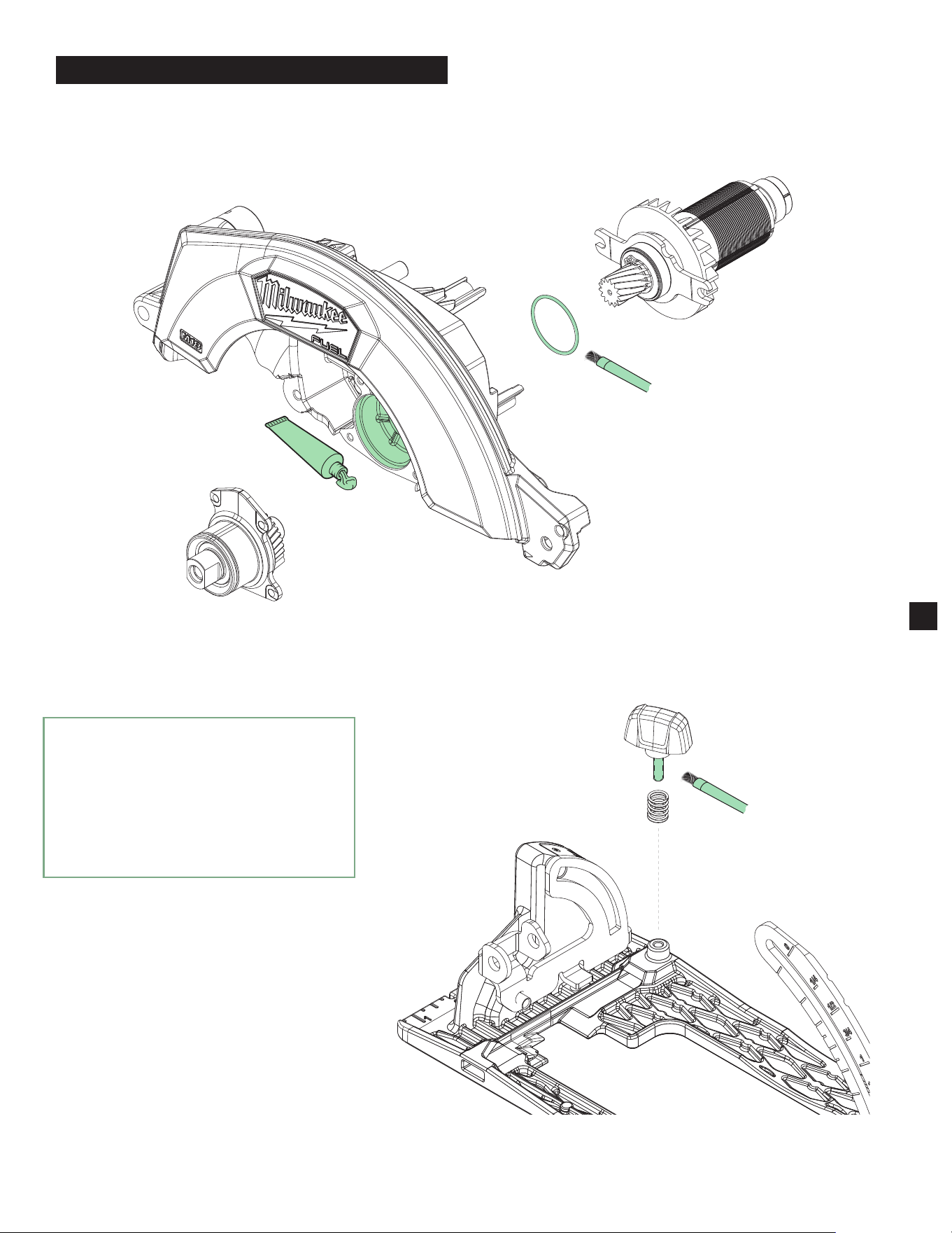
Brush a light coating of grease (about 0.05g)
on the surface of the O-Ring (26)
Apply about 5.5g of grease on the
Upper Guard Gearcase (44) before
assembling the Output Shaft Assembly
Brush a light coating of grease
(about 0.2g) on the thread of
the Rip Fence Knob (37)
LUBRICATION INSTRUCTIONS
4
►
Type "J" Grease
No. 49-08-4220, 1 lb can
Apply thin coat of grease to areas indicated.
NOTE: When servicing, remove 90-95% of the
existing grease prior to installing Type "J".
Original grease may be similar in color but
not compatible with "J".
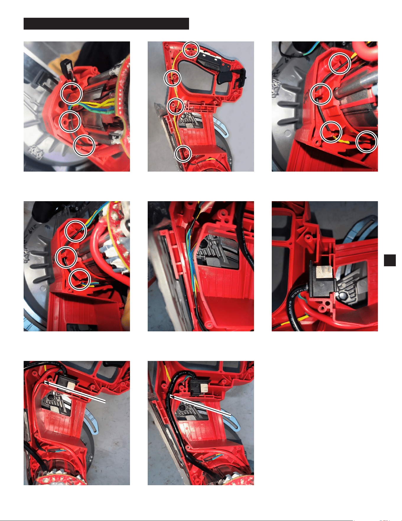
5
WIRING INSTRUCTIONS
1) Press the LED wire into the housing traps
and grooves.
2) Press the switch wire into the housing
traps and grooves.
4) Press the colored wire into the housing
traps and grooves around the stator.
3) Press the switch wire into the housing
traps and grooves around the stator.
5) Press the colored wire into the housing
traps and grooves as shown above.
6) Closeup of Battery Terminal Block and
wires.
7) Press red wire into housing groove
(on top of colored wires).
8) Press black wire into housing groove
(on top of the red wire).
WARNING
• Take notice of wire routing and
position in wire guides and traps
while dismantling tool.
• Be sure that all components of the
electronics kit are seated rmly and
squarely in housing recesses.
• Avoid pinched wires, be sure all wires
and sleeves are pressed completely
down in wire guides and traps.
• Prior to installing housing cover onto
handle support, be sure that there are
no interferences.
• Be sure to check for functionality of
switches and buttons after housing
halves have been secured.