
Loctite 277
NOTE
Regarding parts to receive
thread locking sealant:
Place one to two drops of
the recommended Loctite®
thread locking sealant
(or the equivalent) to the
threads of parts shown
prior to installation.
4
(4x)
1
11
(12x)
10
(2x)
12
75
18
31
19
(2x)
20
76
8
(2x)
7
(2x)
9
30
32
21
29
23
69
24
(2x)
26
42
43
68
44
70
62
61
60
65
22
41
45
46
47
49
33
34
35
36
54
55
56
57
52
59
58
74
50
(4x)
37
38
39
72
73
40
16
13
(3x)
1 4
90
60 61
62 68
70
91
37 38
40
92
7 8
9
93
22 23
29 69
94
26 43
44 45
46 47
95
52 54
58 59
96
55 56
57
97
33 34
35 36
39
98
21 24
100
41 42
101
49 50
102
10 11
12 16
19 20
75 76
103
30 31
104
13 16
18
99
MILWAUKEE TOOL
l
www.milwaukeetool.com
13135 W. LISBON RD., BROOKFIELD, WI 53005
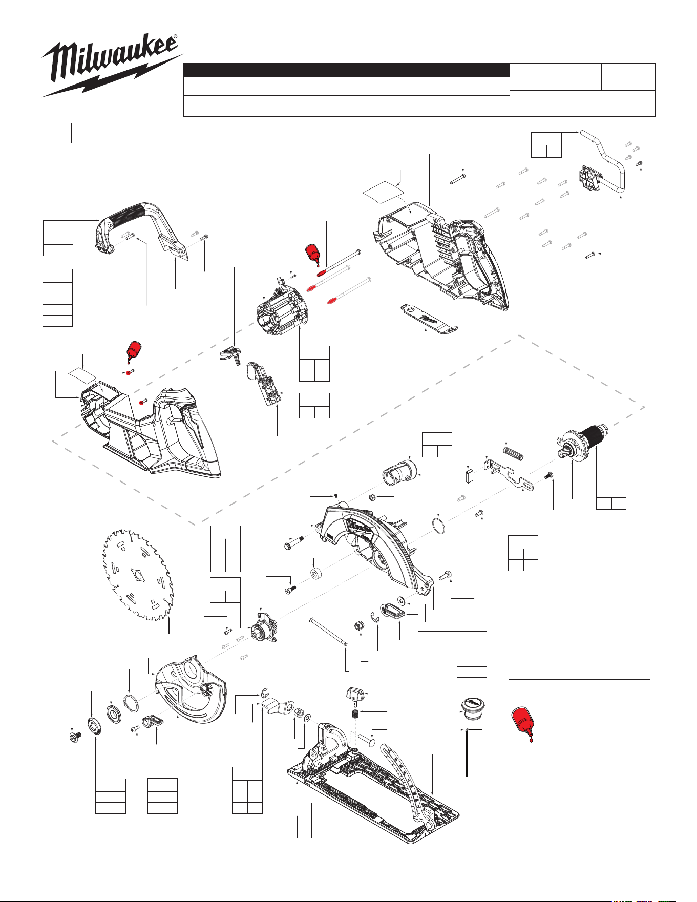
Drwg. 2
BULLETIN NO.
PN0005520
SERVICE PARTS LIST
CATALOG NO. 2930-20
REVISED BULLETIN
SPECIFY CATALOG NO. AND SERIAL NO. WHEN ORDERING PARTS
M18 FUEL™ Rear Handle 7-1/4" Circular Saw
SERIAL NO.
DATE
July 2025
WIRING INSTRUCTION
P85A
See Page 5
0
00
EXAMPLE:
Component Parts (Small #)
Are Included When Ordering
The Assembly (Large #).

FIG. PART NO. DESCRIPTION OF PART NO. REQ.
1 --------------- Rafter Hook (1)
4 05-88-1220 M4 x 10mm Pan Hd. Torx T-20 Screw (4)
7 05-88-5375 M4 x 13.5mm Pan Hd. Torx T-20 Screw (2)
8 05-74-0986 M4 x 15mm Pan Hd. Torx T-20 Screw (2)
9 --------------- Secondary Handle (1)
10 05-74-0023 M4 x 32mm Pan Hd. Torx T-20 Screw (2)
11 --------------- #6-19 Torx T-15 Taptite Screw (12)
12 --------------- Handle Cover (1)
13 --------------- M5 x 105mm Pan Hd. Torx T-25 Screw (3)
16 45-88-0229 M2 x 10mm Pan Hd. Torx T-6 Screw (1)
18 --------------- Stator (1)
19 05-78-1010 M3 x 12mm Pan Hd. Torx T-10 Screw (2)
20 --------------- Handle Support (1)
21 --------------- Rotor (1)
22 --------------- Spindle Lock (1)
23 --------------- Spindle Lock Lever Cover (1)
24 05-74-1030 M5 x 12mm Pan Hd. Torx T-25 Screw (2)
26 02-02-0137 O-Ring (1)
29 45-04-1224 M5 x 10mm Arbor Plate Screw (1)
30 --------------- Switch (1)
31 --------------- Lock Slider (1)
32 45-88-9320 Blade Bolt Wrench (1)
33 --------------- E-Ring (1)
34 --------------- Bevel Adjust Level (1)
35 --------------- Hexagon Nut (1)
36 --------------- Washer (1)
37 43-30-5581 Rip Fence Knob (1)
38 40-50-0650 Spring (1)
39 --------------- M6 x 33mm Bevel Screw (1)
40 --------------- Shoe Assembly (1)
41 --------------- M4 Set Screw for Framer (1)
42 --------------- Dust Collection Outlet (1)
43 06-04-8412 Hexagon Nut (1)
44 --------------- Upper Guard Gearcase (1)
45 06-14-0036 Pivot Shoulder Bolt (1)
46 42-38-0224 Rubber Bumper (1)
47 45-04-0485 M4 x 19mm Pan Hd. Torx T-20 Screw (1)
49 --------------- Output Hub (1)
50 06-82-5285 6-32 Pan Hd. Torx T-15 B Screw (4)
52 --------------- Lower Guard (1)
54 34-60-0177 External Retaining Ring (1)
55 --------------- Inner Blade Flange (1)
SERVICE BILL OF MATERIAL (BOM) LISTING
56 --------------- Outer Flange (1)
57 --------------- Blade Bolt (1)
58 06-82-5314 #10-24 Pan Hd. Torx T-25 Taptite Screw (1)
59 --------------- Lower Guard Lever (1)
60 --------------- Hexagon Nut (1)
61 --------------- E-Ring (1)
62 --------------- Depth Adjust Level (1)
65 49-68-5212 Spring (1)
68 05-85-0056 M6 x 19mm Hex Head M Screw (1)
69 --------------- Spindle Lock Spring (1)
70 --------------- Washer (1)
72 06-67-4624 Dust Port Rubber Plug (1)
73 45-96-6334 M2 Hex Wrench (1)
74 48-40-0740 Blade (1)
75 10-22-2930 Warning Label (1)
76 12-20-2930 Service Nameplate (1)
90 14-36-5887 Rafter Hook Assembly (1)
91 14-46-1233 Depth Adjust Kit (1)
92 14-74-5227 Shoe Kit (1)
93 14-46-1213 Secondary Handle Kit (1)
94 14-46-9841 Spindle Lock Kit (1)
95 14-32-8334 Upper Guard Assembly (1)
96 14-32-8348 Lower Guard Assembly (1)
97 43-34-6229 Blade Nut and Flange Kit (1)
98 14-46-1219 Bevel Adjustment Kit (1)
99 14-20-4993 Electronics Assembly (1)
100 23-40-2499 Inner Rotor Assembly (1)
101 14-46-1228 Dust Kit (1)
102 14-73-9876 Output Shaft Asembly (1)
103 14-46-1214 Handle Cover Kit (1)
104 23-66-0120 Switch Kit (1)
105 49-22-1005 Rip Fence (Not Shown) (1)
FIG. PART NO. DESCRIPTION OF PART NO. REQ.
FIG. NOTES
75,76 A clean, dry surface is essential for proper performance for
any adhesive system. The area intended for application of
any adhesive label or nameplate must be prepared by
cleaning with isopropyl alcohol. The solvent is to be applied
with a clean, lint free applicator and the surface allowed to
dry before applying the label or nameplate.
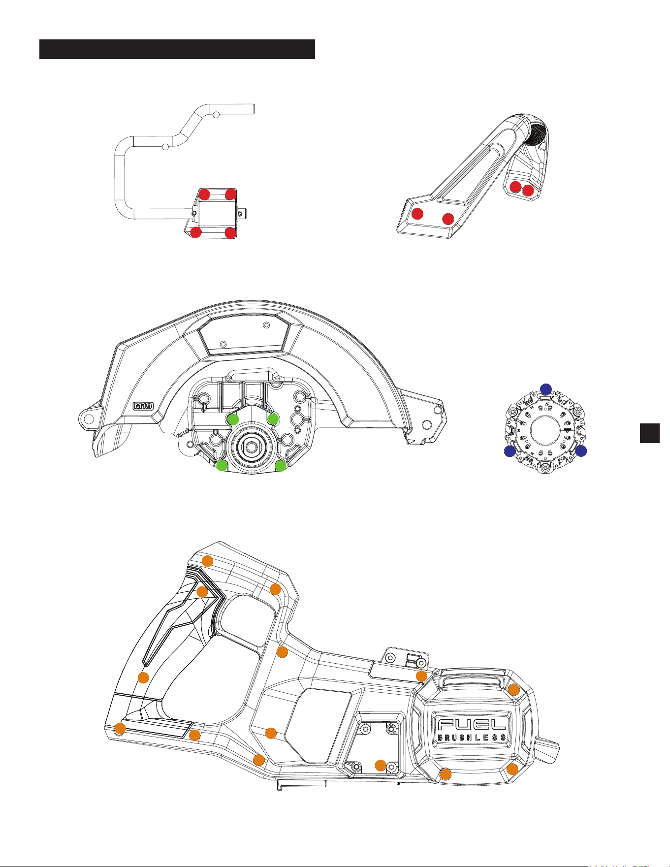
SEAT TORQUE
FIG. PART NO. DESCRIPTION OF FASTENER QTY WHERE USED (kgf-cm) (lb-in)
4 05-88-1220 M4 x 10mm Pan Hd. Torx T-20 Screw 4 Rafter Hook Base Plate (5) 12 ± 1 10 ± 1
7 05-88-5375 M4 x 13.5mm Pan Hd. Torx T-20 Screw 2 Secondary Handle (9) 12 ± 1 10 ± 1
8 05-74-0986 M4 x 15mm Pan Hd. Torx T-20 Screw 2 Secondary Handle (9) 11 ± 1 9.5 ± 1
10 05-74-0023 M4 x 32mm Pan Hd. Torx T-20 Screw 2 Handle Cover (12) 15 ± 1 13 ± 1
NOTE - Screw driver speed is lower than 800RPM
11 --------------- #6-19 Torx T-15 Taptite Screw 12 Handle Cover (12) 13 ± 2 11 ± 1
13 --------------- M5 x 105mm Pan Hd. Torx T-25 Screw 3 Stator (18) 18 ± 2 16 ± 1
16 45-88-0229 M2 x 10mm Pan Hd. Torx T-6 Screw 1 Stator (18) 2.5 ± 0.2 2.2 ± 0.2
19 05-78-1010 M3 x 12mm Pan Hd. Torx T-10 Screw 2 Handle Support (20) 10 ± 1 9 ± 1
24 05-74-1030 M5 x 12mm Pan Hd. Torx T-25 Screw 2 Rotor Retaining Plate (25) 30 ± 3 26 ± 3
29 45-04-1224 M5 x 10mm Arbor Plate Screw 1 Spindle Lock (22) 21 ± 2 18 ± 2
30 --------------- Switch (Screws in Switch) 1 Switch with Lock Slider (31) 10 ± 1 9 ± 1
35 --------------- Hexagon Nut 1 Shoe Assembly (40) - Bevel Adjustment 22 ± 1 19 ± 1
41 --------------- M4 Set Screw for Framer 1 Dust Collection Outlet Nozzle (42) 15 ± 1 13 ± 1
NOTE - Us corner screwdriver, only travel 4 rotations
45 06-14-0036 Pivot Shoulder Bolt 1 Upper Guard Gearcase (44) 22 ± 2 19 ± 2
47 45-04-0485 M4 x 19mm Pan Hd. Torx T-20 Screw 1 Upper Guard Gearcase (44) 35 ± 3 30 ± 3
50 06-82-5285 6-32 Pan Hd. Torx T-15 B Screw 4 Output Hub (49) 17 ± 3 15 ± 3
57 --------------- Blade Bolt 1 Outer Flange (56) 10 ± 1 9 ± 1
58 06-82-5314 #10-24 Pan Hd. Torx T-25 Taptite Screw 1 Lower Guard Lever (59) 35 ± 3 30 ± 3
60 --------------- Hexagon Nut 1 Depth Adjust Level (62) 40 ± 4 35 ± 3
SCREW TORQUE SPECIFICATIONS
2
1
2
3
4
5
6
7
8
9
10
11
12
14
13
1
2
3
4
1
2
3
4
1
2
3
4
1
2
3
Stator (18)
Secondary Handle (9)
Rafter Hook (1)
Upper Guard Gearcase (44)
Handle Cover (12)
HOUSING SCREWS - FASTENING ORDER
3
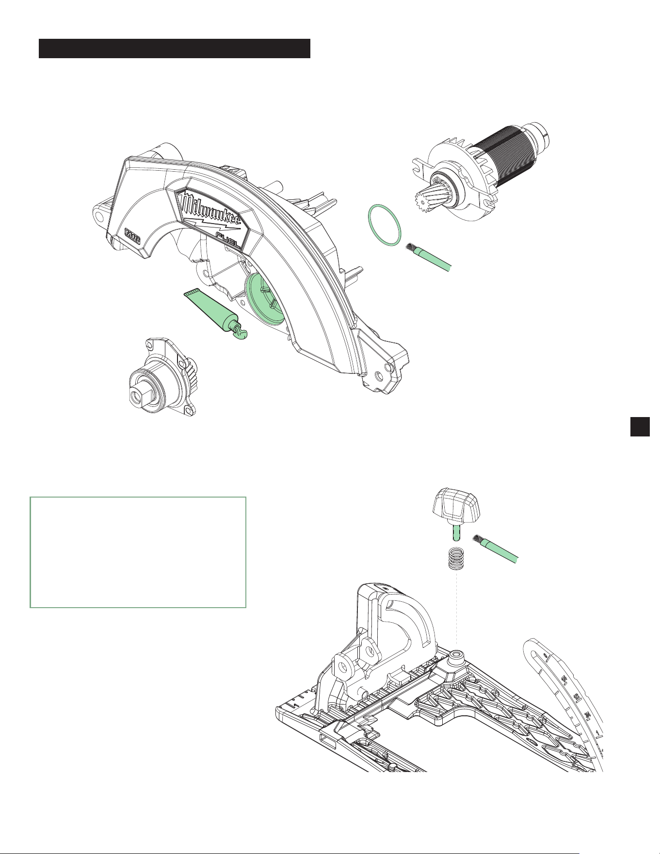
Brush a light coating of grease (about 0.05g)
on the surface of the O-Ring (26)
Apply about 5.5g of grease on the
Upper Guard Gearcase (44) before
assembling the Output Shaft Assembly
Brush a light coating of grease
(about 0.2g) on the thread of
the Rip Fence Knob (37)
LUBRICATION INSTRUCTIONS
4
►
Type "J" Grease
No. 49-08-4220, 1 lb can
Apply thin coat of grease to areas indicated.
NOTE: When servicing, remove 90-95% of the
existing grease prior to installing Type "J".
Original grease may be similar in color but
not compatible with "J".
5
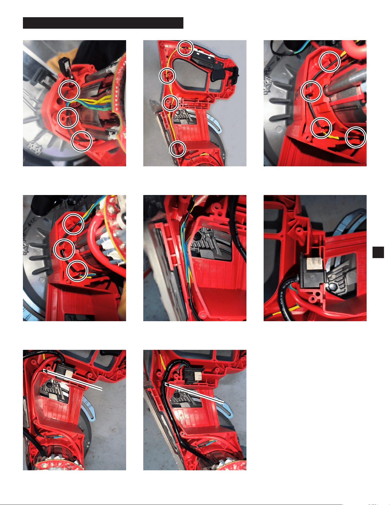
WIRING INSTRUCTIONS
1) Press the LED wire into the housing traps
and grooves.
2) Press the switch wire into the housing
traps and grooves.
4) Press the colored wire into the housing
traps and grooves around the stator.
3) Press the switch wire into the housing
traps and grooves around the stator.
5) Press the colored wire into the housing
traps and grooves as shown above.
6) Closeup of Battery Terminal Block and
wires.
7) Press red wire into housing groove
(on top of colored wires).
8) Press black wire into housing groove
(on top of the red wire).
WARNING
• Take notice of wire routing and
position in wire guides and traps
while dismantling tool.
• Be sure that all components of the
electronics kit are seated rmly and
squarely in housing recesses.
• Avoid pinched wires, be sure all wires
and sleeves are pressed completely
down in wire guides and traps.
• Prior to installing housing cover onto
handle support, be sure that there are
no interferences.
• Be sure to check for C functionality
of switches and buttons after housing
halves have been secured.