
Operator’s Manual
www.mechmaxx.com
WARRANTY


MAX performance,MAX Value,MAX Support that’s
Flail Mower
Enhanced design features come standard
Engineered for the best user experience
Quality metal parts are used instead of plastic
A robust warranty supports all products
Budget-friendly prices make it practical
TABLE OF CONTENTS
TABLE OF CONTENTS
SPECIFICATIONS
SAFETY SIGNS
SAFETY INFORMATION
1
2
BRIEF INTRODUCTION
MAIN COMPONENTS OF THE FLAIL MOWER
3
4
5
5
5
CHECKING BEFORE OPERATING
ADJUSTING THE HEIGHT
FLAIL MOWER ADJUSTMENT
6
6
6
6
REGULATING THE TENSION OF DRIVING BELT
7
STARTING UP
7
SERVICE
MAINTENANCE
SEASON MAINTENANCE
8
8
8
ANNUAL MAINTENANCE
8
STORAGE
9
OPERATION AFTER STORAGE
9
SPECIFICATIONS
OPERATION
8
SERVICE AND MAINTENANCE
10
ILLUSTRATED PARTS CATALOGUE
11
EFS FLAIL MOWER PARTS LIST
Your new Flail Mower offers quality construction, and is
easy and safe to operate. With proper use and care, it is
designed to give you many years of dependable service.
Prepare to experience the durability to take on any job
with the ease, portability, and convenience of your new
Flail Mower !
1
www.mechmaxx.com
TABLE OF CONTENTS

SPECIFICATIONS
2
www.mechmaxx.com
SPECIFICATIONS
Engine Power Required
Working Width
Overall Width
Blade Ground Clearance
Max. Cutting Diameter
Number Of Blades
Blade Type
Size Of Blades
Blade Weight
Blade (Tines) Material
Rotor Bearing
Rotor Diameter
Rotor Swing Diameter
Rotor Thickness
Rotor Shaft Speed
Blade Speed
Drive Type
Number Of Belts
Belt Size
Drive Belt Tensioner
Deck Material
Side Plate Material
PTO Shaft RPM
Driveline Shaft Length
Spline End
3-Point Hitch
Gearbox Oil Type
Dimensions (L x W x H)
Finish
Warranty
Weight (N.W./G.W.)
15-35HP
48in
56in
0.6in-1.8in
Depends On The Type Of Grass
20
Hammer
3.5 X 3 X 1.6in
0.8lbs
Cast Steel
SKF Bearing
3in
11in
0.3in
2958 rpm
142 ft/s
Belt Drive
3
V Belt 13X1041
Yes
0.16in
0.24in
540 RPM
T5-LF-31 With Shear Bolt; 31in- 43in
1.375in z6
CAT 1
85W-90
57 × 30 × 28in
Powder Coating
1 Year
379/470 Ibs
60in
65in
24
65 x 30 x 28in
406/503 Ibs
25-45HP
65in
72in
26
72 x 30 x 28in
702/820 Ibs
Model EFS48 EFS60 EFS65
3
www.mechmaxx.com
SAFETY SIGNS
The rating plate on your machine may show symbols. These represent important information about the product or instruc-
tions on its use.
SAFETY SIGNS
The PTO Driveline MUST be
measured and cut (if required) as
per the Owner's Manual.
Failure to do so will result in
damage to both the tractor
and the implement.
ENGAGE TRACTOR
CLUTCH SLOWLY
DURING START UP OR
DAMAGE WILL OCCUR.
KEEP PTO SHAFT
WITH 25°OF LEVEL
DURING OPERATION.
All driveline guards, tractor, and equipment
shields in place.
ROTATING DRIVELINE
CONTACT CAN CAUSE DEATH
KEEP AWAY!
DO NOT OPERATE WITHOUT :
DO NOT go under frame when rotor is turning or engine
is running. Keep others away.
ROTATING KNIVES HAZARD
Disconnect & lockout power source BEFORE adjusting
or servicing.
Keep hands, feet, hair, and clothing away from moving
parts.
Do not open or remove safety shields while
engine is running.
Drivelines securely attached at both ends.
Driveline guards that turn freely on driveline.
ROTATING
BLADES
KEEP HANDS
AWAY
Read and understand
operators manual
before using this
machine.
High Pressure Fluid Hazard.
High pressure fluid leak will pierce skin.
Release pressure before working on system.
Fluid injected into skin will injure or kill.
Detect leaks with wood or cardboard.
Wear sturdy gloves and goggles.
NEVER use fingers.
Fluid injected in skin must be surgically
removed by trained doctor immediately or
gangrene will result.
To prevent serious injury or death from rotating knives:
Read and understand Operator's manual before using.
Operate with guards installed and in good condition.
Operate only with tractor equipped with ROPS and
seatbelts.
Keep away from moving parts.
Stop engine, set brake and wait for all moving parts to
stop before dismounting.
Be sure lights and reflectors required by law are clean
and in good working order before transporting.
Do not allow children to operate mower.
Travel with SMV and lights that follow local codes.
Clean debris from mowing area.
Do not operate in the raised position.
Support securely before working beneath unit.
Review safety instructions annually.
Do not permit riders on the tractor or mower. Never carry
child on tractor seat.
To Prevent Serious Injury Or Death:
PINCH POINT
HAZARD
Keep clear
GUARD MISSING
WHEN THIS IS VISIBLE
DO NOT OPERATE
ENTANGLEMENT HAZARD
BELT DRIVE:
HAND AND ARM
ENTANGLEMENT
HAZARD.
FLYING OBJECTS
HAZARD
Keep clear.
Relieve pressure before disconnecting lines.
Do Not use hands to check for leaks.
Consult physician immediatly if skin
penetration occurs.
HIGH PRESSURE FLUID
HAZARD

4
www.mechmaxx.com
SAFETY FIRST
SAFETY INFORMATION
SAFETY
Read this service manual before using the machine.
This machine is designed for pulverizing grass and short
bramble, and shall be used in the indicated purpose. You
take the responsibility if the machine is used in any other
purposes.
For safety of personnel and good performance of the
machine, you shall check the performance of the machine
and the tractor before starting the machine.
Keep all persons and animals away from the machine
when starting it.
The operator shall not wear overly loose clothing during
operating the machine.
Do not touch the rotor when the machine rotates.
Keep away from the machine when it moves.
Before repairing the machine, stop all movable parts and
the tractor, remove the key and keep it with you.
Always keep the machine in a good state, if necessary,
repair or change the defective parts.
Don't use the machine to transport personnel.
Don't modify the machine.
Be careful of sharp and pointed parts during repairing the
machine.
All protective parts shall be guaranteed to be in good
state before starting the machine.
Don't leave the tractor when moving the machine; and
always take away the key of the tractor with you.
The machine shall be operated in the recommended
speed.
Don't stay between the tractor and the machine.
Don't start the machine in a closed place (due to the
smoke from the tractor).
This safety alert symbol indicates import-
ant safety messages in this manual. When
you see this symbol, carefully read this
message that follows and be alert to the
possibility of personal injury or death.
5
www.mechmaxx.com
SPECIFICATIONS
SPECIFICATIONS
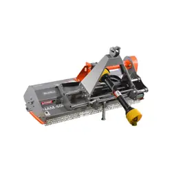
BRIEF INTRODUCTION
MAIN COMPONENTS OF THE FLAIL MOWER
Read this service manual before using the machine.
Flail mower is designed for pulverizing grass and short bramble, and shall be used in the indicated purpose.
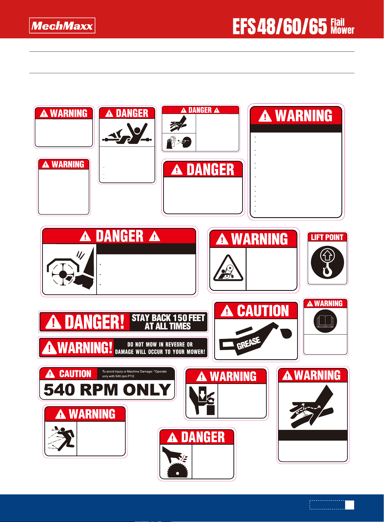
The Flail mower consists of a rotating shaft with many blades attached to it. The blades cut the grass while traveling over
the working area. Rotational power to the shaft is provided by the tractor PTO through the gearbox in the center of the
machine.
The Flail mower attaches to the 3 point hitch on the tractor.
1. Blade axle
2. Blade axle cover
3. Combined fender
4. Gear box assembly
5. Suspension bracket
6. Transmission shaft
7. Belt wheel and belt
6
www.mechmaxx.com
OPERATION
OPERATION
CHECKING BEFORE OPERATING
ADJUSTING THE HEIGHT
FLAIL MOWER ADJUSTMENT
Before operating the machine, the following areas should
be checked off:
1.Before starting up the machine, check and Lubricate all
grease points, all lubricated parts inside the machine.
2.Use only an agricultural tractor of horsepower within
limits of the machine specified.
3.Check that the machine is properly attached to the
tractor. Be sure retainers are used on the mounting pins.
4.Be sure extra weights are mounted on the front of the
tractor.
5. Check the oil level in the gearbox. Add as required.
6.Check that the tractor PTO shaft turns freely and that
the machine driving shaft can telescope easily.
7.Check the blades. Be sure they are not damaged or
broken and swing freely in their mount. Repair or replace
as required.
8.Check and tighten the blade bolts.
9.Check for entangled material in all rotating parts.
Remove this material.
10. Install and secure all guards, doors and covers before
starting.
11. Before installing the universal joint, the tractor and
the machine motor shall be stopped and the key be taken
away. The universal joints shall be installed in good state,
with proper protective parts.
12.The chain on the protective parts of the universal joint
must be in good condition to prevent automatic rotation.
13.All other persons shall leave the ground before
connecting the driving power from the tractor. Keep the
output of the tractor at 540 RPM.
14.Before cleaning, repairing and lubricating the machine,
stop the motor and take away the key with you.
15.When the universal joint is not connected with the
tractor, they must be connected again through the frame
to protect the joint from damaging.
16.Don't approach the machine when the machine runs.
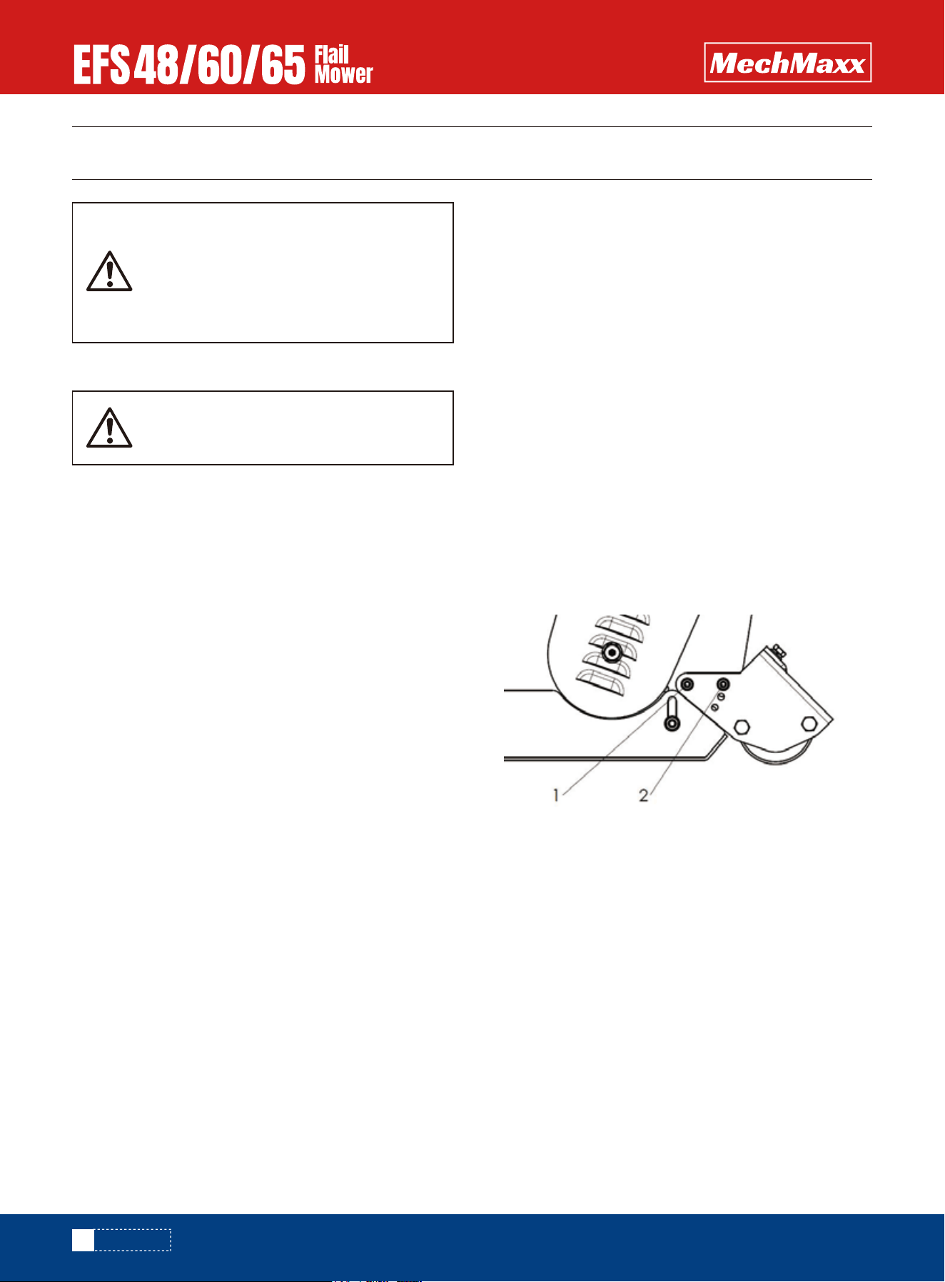
To get the most out of your flail mower, it should be set
within the recommended height.To save fuel and power
and reduce wear and tear, the cutting height must be
regulated correctly.When adjusting the working height,
loosen screw (1), remove screw (2) on both sides; The
roller height (see following drawing) can be adjusted by
alligning the selected hole in the roller support bracket at
position 2. The lowest hole is the highest working height;
put the screw (2) into the selected hole; tighten screw
(1) and screw (2).
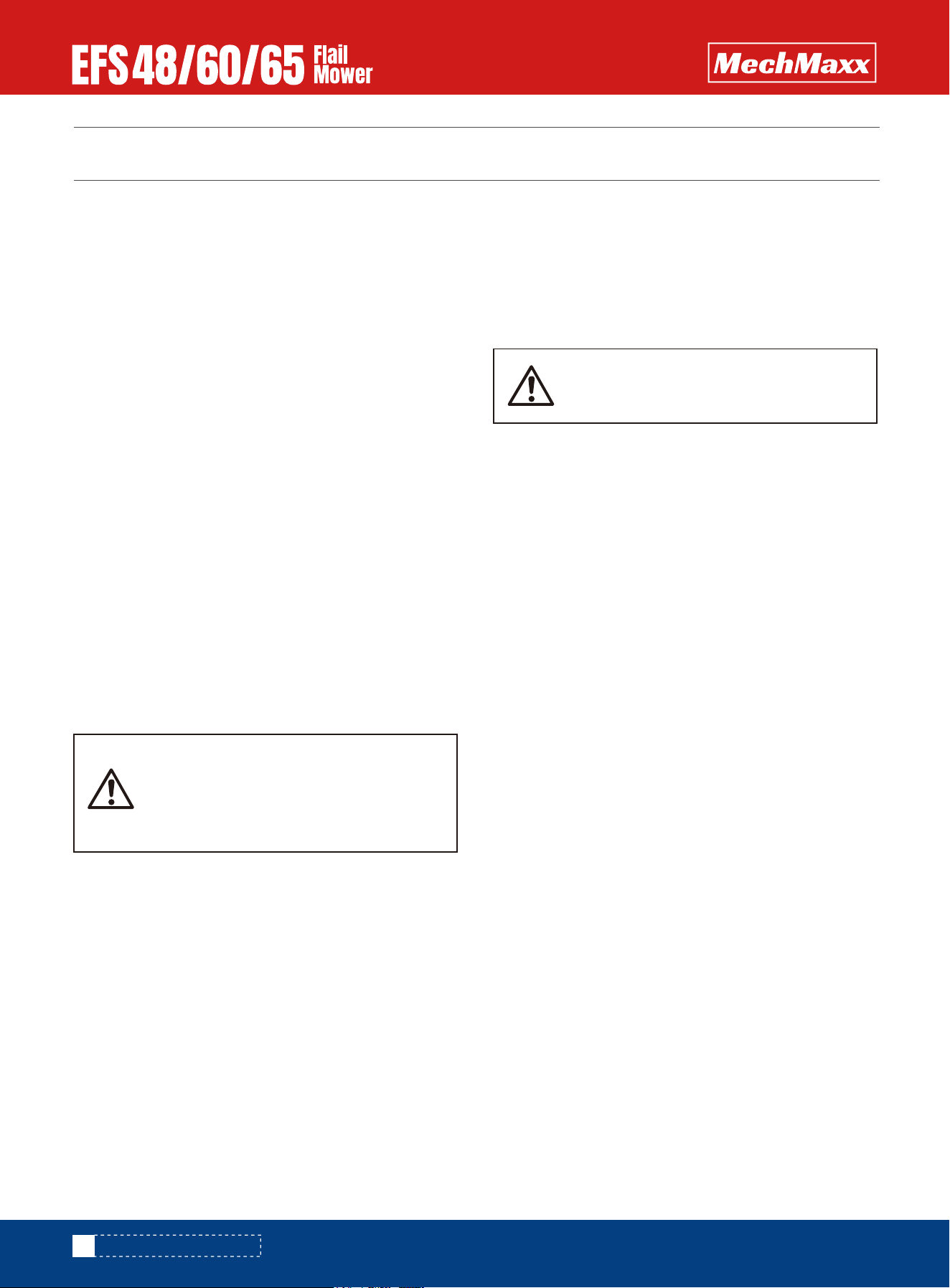
1. On a flat piece of ground, attach the Flail Mower to the
Tractor using the three point linkage
2. Use a solid adjustable top link
3. Lower the three point linkage to its lowest position
4. With the roller at the rear in contact with the ground,
adjust the length of the top link so that the lower edge at
the side of the flail mower is parallel with the ground
5. Rotate the blade drum by hand so that a row of blades
hang vertically towards the ground.
6. Measure the clearance between the bottom of the
extended blades and the ground.
Minimum 50mm
Note in rough or lumpy paddocks the clearance needs to
be increased to ensure that the blades dont impact the
ground in operation.
Be familiar with the machine before start-
ing. Read this manual carefully to learn
how to operate the machine safely and
how to set it to provide maximum field
efficiency.
Only use universal joint conforming to CE
standard and protect them properly.
7
www.mechmaxx.com
OPERATION
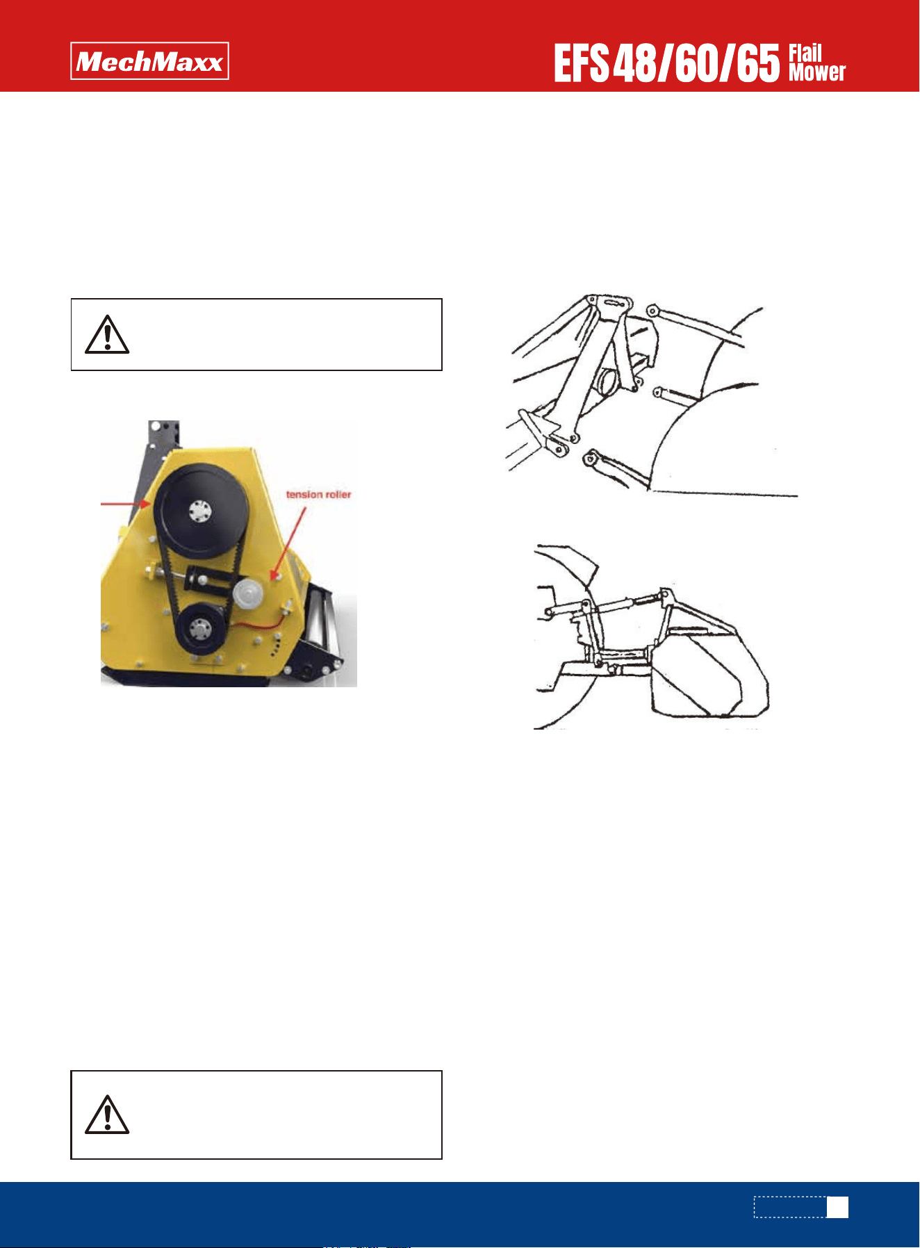
REGULATING THE TENSION OF DRIVING BELT
STARTING UP
7. Adjust the roller height to increase or decrease the
blade clearance as required
8. Go through steps 4 to 7 until the required clearance is
achieved.When the Flail Mower has been set up with the
required tolerances:Operate the Flail Mower with tractor
in low range and the PTO delivering 540 RPM
The machine coupling is equipped with 3 pins so that the
machine can be coupled with all tractors with universal
coupling with 3 pins. Each telescopic pole on the machine
can be adjusted properly according to the type of the
tractor. Keep the Flail mower away the tractor with a
certain distance. The universal joint must not be extend-
ed to its limit and the largest distance in the closed state
shall be 1/2 in.
Moving the lifting arm, and putting it between axes, insert
the joint pins and fix them with pins. Fix the lifting arm
with chain and tensioning device so as to prevent lateral
movement of the machine. Connect the universal joint to
the PTO shaft of the tractor on the side of the tractor. In
any event, it cannot produce a collision in any position.
While connecting 3 points, pay attention to that the PTO
shaft of the tractor shall be parallel with the ground. It is
very important to keep the machine driving axle and the
PTO shaft of the tractor in parallel.
The machine shall be lifted from the ground before moving
the machine.
1. Adjust the drive belt tension. The correct belt tension is
achieved when the belt can be deflected by the belt thick-
ness about 10mm at the center point between the
pulleys.
2. Align the gearbox so the drive shaft is parallel with the
body.
3. Use a straight edge to make sure the belt pullies are in
line and running true. If misaligned,call your dealer or
service agent for technical support.
Before starting the machine, control and adjust the
following items:
• Tension of trapezoidal driving belt.
• Oil level of gear.
• Point of lubrication
• All bolts, nuts and screws.
Remove the driving belt cover.
The machine shall always stand still for
regulating the tension.
When transferring the moving state of the
machine to the working state, do not stand
between the machine and the tractor.
8
www.mechmaxx.com
SERVICE AND MAINTENANCE
SERVICE AND MAINTENANCE
SERVICE
SEASON MAINTENANCE
MAINTENANCE
FLUIDS AND LUBRICANTS
GREASING
NOTE:The operator shall put on gloves and use suitable
tools before changing blade.
1.Grease:
Use multi-purpose lithium based grease.
2.Gear Box Oil:
Use 85W-90 drive &hydraulic dual-purpose oil or equiva-
lent for all operating
Each Gearbox Capacity: 0.85 liter
3.Storing Lubricants:
Your machine can operate at top efficiency only if clean
lubricants are used. Use clean containers to handle all
lubricants. Store them in an area protected from dust,
moisture and other contaminants.
By following a careful service and maintenance program
for your machine, you will enjoy many years of trouble-free
operation.
The period recommended is based on normal operating
conditions. Severe or unusual conditions may require
more frequent maintenance.
• Check and screw all nuts and bolts in connection parts.
• Check the blade and fixing parts every day and replace
the damaged parts if they are found damaged. Don't
install damaged, worn and unbalanced blade.New
sleeve shall be used to replace the worn fixing parts on
the blade.
8 HOURS OR DAILY MAINTENANCE
• Use a hand-held grease gun for all greasing.
• Wipe grease nipple with a clean cloth before greasing,
to avoid injecting dirt and grit.
• Replace and repair broken nipple immediately.
• If nipples will not take grease, remove and clean
thoroughly. Also clean lubricant passageway. Replace
nipple if necessary.
• Check the oil in gearbox. Fill it up to the recommended
level if necessary.
• Press grease in each oil nipple three to five times.
• Clean the implement; take away all grass and mud.
• Check the machine as below beside the terms of daily
maintenance.
• Check the oil in gearbox; replace it if it is bad.
• Check the bearings of blade spindles whether mud and
water have been enter because oil seals are damaged,
if it's so, disassemble and clean them and replace them
if it is necessary. And then press grease into them.
• Check the distance between bearings and gears. Adjust
them if it's necessary.
ANNUAL MAINTENANCE
• Cleaning mud and grass on the machine thoroughly.
• If you have replaced bearings or gears, check all clear-
ances and run the machine without load for 3-5
minutes.
• Check and clean blade axles. Replace oil seals and
press grease into them.
• Check all blades, replace then if they are wear-out or
damaged.
• Repair the side skirts; let them to original technical
condition. Replace damaged or broken protective devic-
es.
• Remove the driving shaft from the machine. Pull the
machine driving shaft apart. Check and replace any
components that are damaged or worn. Install the drive
line on the machine. The machine driving shaft should
telescope easily and the guard turn freely on the shaft
• Let the oil in gearbox drain out thoroughly. Check and
clean it. Fill new gear oil up to the dedicated oil level.
• The oil shall be drained off after 50 hours of using time.
Then the oil shall be drained off every 250 hours. One
time every year at least.
All maintenance, repairing, cleaning and
lubricating shall be conducted when the
tractor and motor are stopped and the key
is taken away.
Check the oil level only when the unit is
cold and the machine is on the level.
9
www.mechmaxx.com
SERVICE AND MAINTENANCE
STORAGE
OPERATION AFTER STORAGE
• The draining procedure is as follows: remove the drain-
ing bolt under the gear box, so that the oil drains off.
After the oil is drained off, put back the cover and fill the
gear oil up to the dedicated oil level.
The machine inside and outside shall be cleaned carefully
so as to avoid corrosion.
Don't spray water on the rolling bearing if you clean the
machine with high pressure sprayer.
Check and clean the universal joint, driving belt press
roller, or replace them if they are not in good state.
Spread oil on all parts required.
Recoat the part rubbed and damaged for anti corrosion.-
Store the machine in a dry, level area. Support the frame
with planks if require.
Before the machine is started up, check the following
items regularly:
Check oil level and add it if not enough.
Check and tighten all screws and nuts;
Check the machine's setup and adjustment.
Check the blade state.
Check the air hole on the gearbox. If it is blocked, clean or
open the hole with compressed air.
Don't spread oil or grease on the driving belts. If there is
oil or grease on the belts, wipe the belts, in case the belt
sliding and wearing occur.
Check all tightening parts and replace them if necessary.
Don't remove the protective parts on some points and
protect the machine.
Check the machine every 10 hours. Repair
the damaged parts or replace the blade
according to the manufacturer's recom-
mendation, to keep the machine balanc-
ing.
In the case of vibration, stop the machine
and check the blade. If the blade breaks or
is damaged, replace it with same type of
the blade. If the machine vibrates still,
send the machine to the authorized
repairer.
Don't forget to disconnect the generator
cable and batteries when welding on the
machine, even when it is not coupled with
the tractor.
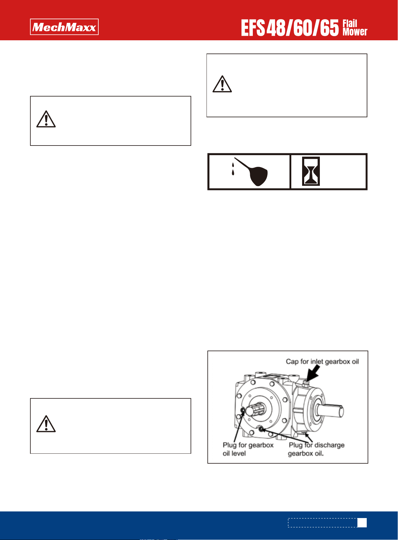
CHECK GEARBOX OIL
Type of Lubrication: SAE85W/90 Gear Lube
Check oil level in gearbox by removing the plug located on
the right-hand side. Oil should be level with bottom of plug
hole. Add oil if necessary, by removing top fill plug and side
plug. Add oil until it flows from side plug hole.
Do not overfill!
IMPORTANT: Mower should be level when checking oil in
gearbox!
LUBRICATION
Gearbox
Type of Lubrication: SAE85W/90 Gear Lube
AS
REQUIRED
Check oil level in gearbox by removing the plug located on
the right hand side. Oil should be level with bottomof plug
hole. Add oil if necessary by removing top fill plug and side
plug. Add oil until it flows from side plug hole.
Do not overfill!
IMPORTANT: Mower should be level when checking oil in
gearbox!

ILLUSTRATED PARTS CATALOGUE
ILLUSTRATED PARTS CATALOGUE
10
www.mechmaxx.com
The manual contains a parts list for your machine. It is divided into major sections, which correspond to the groups shown
in the Table of Contents and the accompanying illustration.
The first page of each major section lists the contents of that section, each of which consists of exploded views and
related tabular listings. When ordering parts
Always give your dealer the Model of your machine to assist him in ordering and obtaining the correct parts. Use the
exploded view and tabular listing of the area of interest to exactly identify the required part.

EFS FLAIL MOWER PARTS LIST
EFS FLAIL MOWER PARTS LIST
REF DESCRIPTION QTY
1
2
3
4
5
6
7
8
9
10
11
12
13
14
15
16
17
18
19
20
21
22
23
24
25
26
27
28
29
Linkage Weldment (L)
Lock Pin 8*40
Top Link Weldment
Pin
Bolt M12*35
Lock Nut M12
Linkage Weldment (R)
Hook
Bolt M6*20
Lock Nut M6
Weldment For Gearbox
Weldment For Gearbox1
Bolt M10*35
Big Washer 10
Locking Nut M10
Gearbox
PTO Cover
Bolt M8*16
Washer 8
Bolt M10*40
Paper Gaset
Bolt M8*40
Breath Bolt
Transmission Shaft
Bolt
Bolt M8*40
Shaft
Bearing
Circlip 62
1
3
1
1
8
12
1
1
2
2
1
1
4
8
16
1
1
7
25
8
1
4
1
1
1
1
1
1
1
REF DESCRIPTION QTY
30
31
32
33
34
35
36
37
38
39
40
41
42
43
44
45
46
47
48
49
50
51
52
53
54
55
56
57
58
Oil Seal FB30*62*10 Big Washer 10
Power Lock 25*50
Big Pulley
Belt
Pulley Cover
Mower Deck
Nut M12
Washer 12
Tension Plate
Bearing 6005 1RS
Tension Roller
Washer
Bolt M12*30
Roller Connection Plate (Left)
Rear Roller
Scraper
Bearing L204
Roller Connection Plate (Right)
Bolt M10*35
Grease nipple M8*1
Skids
Low Pin
Bushing
R Pin
Stand Foot Weldment
Pin
Bolt M8*25
Cover Plate
Clip
1
2
1
3
1
1
2
7
1
2
1
1
1
1
1
1
2
1
4
2
2
2
2
1
1
1
16
2
2
11
www.mechmaxx.com

12
www.mechmaxx.com
REF DESCRIPTION QTY
59
60
61
62
63
64
65
66
67
68
69
70
71
72
73
74
Fender (Left)
Fender
Shaft Bar For Fender
Fender
Fender (Right)
Bearing Protection
Bearing
Ring For Grass
Rotor Weldment
Bolt M12*1.5*50
Hammer
Locking Nut M12*1.5
Bolt M8*20
Pipe For Grease
Grease nipple M6*1
Small Pulley
1
14
1
1
1
1
2
2
1
24
24
24
4
1
1
1
EFS FLAIL MOWER PARTS LIST