Hearth & Home Technologies • CK-30 Cabinet Kit Installation Manual • 4126-900 Rev D • 2/241
Installation/Owner’s Manual
Installation and Appliance Setup
INSTALLER: Leave this manual with party responsible for use and operation.
OWNER: Retain this manual for future reference.
- DO NOT store or use gasoline or other ammable
vapors and liquids in the vicinity of this or any other
appliance.
- What to do if you smell gas
• DO NOT try to light any appliance.
• DO NOT touch any electrical switch; do not use any
phone in your building.
• Immediately call your gas supplier from a neighbor’s
phone. Follow the gas supplier’s instructions.
• If you cannot reach your gas supplier, call the re
department.
- Installation and service must be performed by a qualied
installer, service agency, or the gas supplier.
WARNING: If the information in these
instructions is not followed exactly, a fire or
explosion may result causing property damage,
personal injury, or death.
HOT GLASS WILL CAUSE
BURNS.
DO NOT TOUCH GLASS
UNTIL COOLED.
NEVER ALLOW CHILDREN
TO TOUCH GLASS.
A barrier designed to reduce the risk of burns
from the hot viewing glass is provided with this
appliance and shall be installed for the protection
of children and other at-risk individuals.
!
DANGER
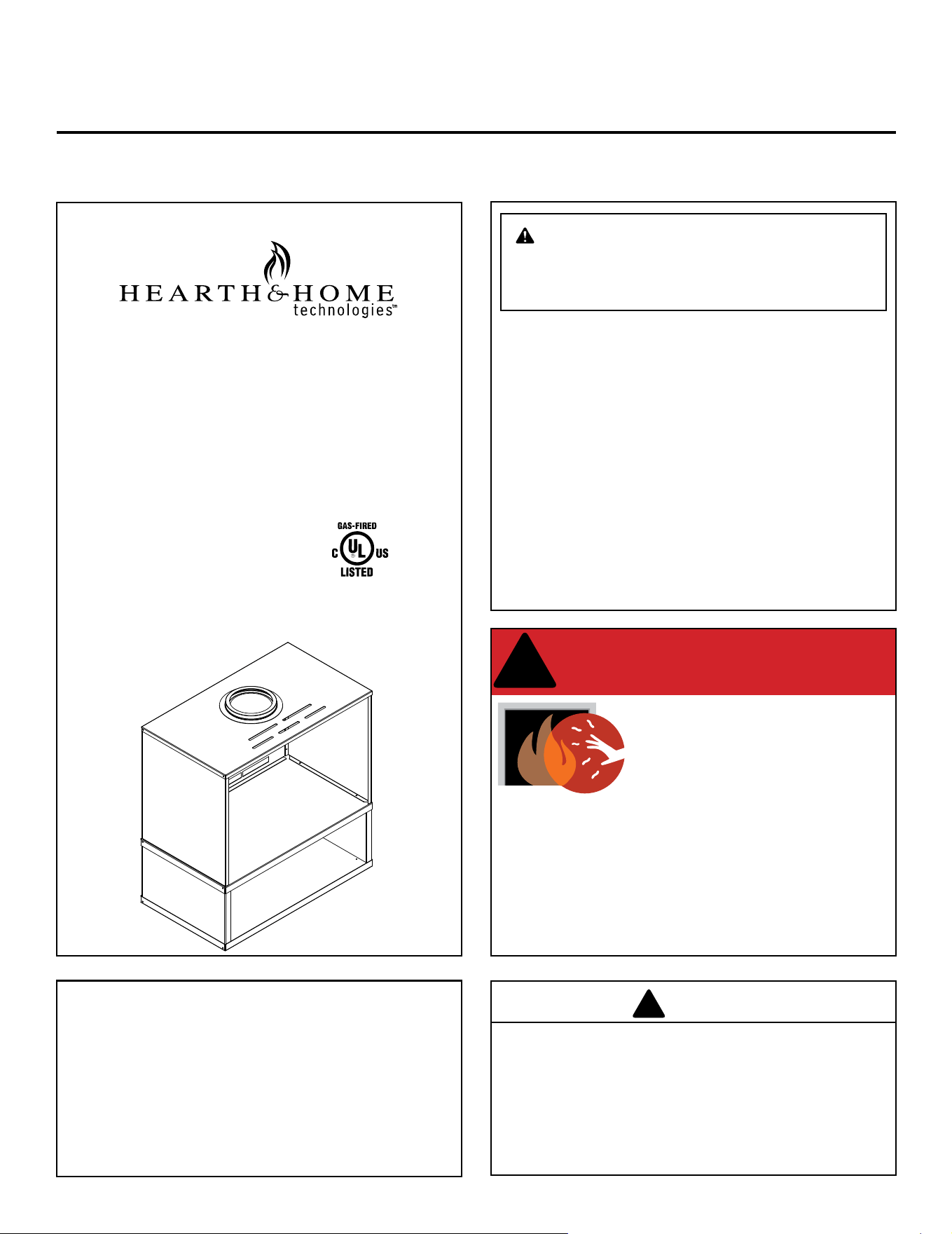
Models:
CK-30
ADP-CK30
The CK-30 Cabinet Kit must be used with
the ADP-CK30 adapter kit, INFIT-30-BK
front along with one of the following inserts:
EXCURSION-II
RUBY30IN
RUBY30IL
SUPREME-I30-IFT
SUPREME-I30-BIR
SUPRM-I30LP-IFT
TRILLIANT30IN
NOTICE: SAVE THESE INSTRUCTIONS
This appliance may be installed as an OEM installation
in manufactured home (USA only) or mobile home and
must be installed in accordance with the manufacturer’s
instructions and the manufactured home construction
and safety standard, Title 24 CFR, Part 3280 or Standard
for Instllation in Mobile Homes, CAN/CSA Z240MH, in
Canada.
This appliance is only for use with the type(s) of gas
indicated on the rating plate.
The surface of the appliance is hot when it is in use.
Young children should be watched carefully when they
are in the same room when the appliance is in use, and
they should be taught to avoid the hot surface. Keep
any objects that can burn well away from the appliance,
and observe the recommended clearances that follow.
WARNING
!
►

Hearth & Home Technologies • CK-30 Cabinet Kit Installation Manual • 4126-900 Rev D • 2/242
Safety Alert Key:
• DANGER! Indicates a hazardous situation which, if not avoided will result in death or serious injury.
• WARNING! Indicates a hazardous situation which, if not avoided could result in death or serious injury.
• CAUTION! Indicates a hazardous situation which, if not avoided, could result in minor or moderate injury.
• NOTICE: Used to address practices not related to personal injury.
1 Product Specic and Important Safety Information
A. Kit Contents CK-30. . . . . . . . . . . . . . . . . . . . . . . . . . . . . . . 3
B. Kit Contents ADP-CK30 ........................... 4
C. Replacement Parts CK-30 and ADP-CK30 ............5
2 Getting Started
A. Design and Installation Considerations ...............6
B. Tools and Supplies Needed ........................6
C. Inspect Appliance and Components ..................6
3 Framing and Clearances
A. Appliance Dimension Diagram ...................... 7
B. Clearances to Combustibles .......................8
C. Hearth Extension/Floor Protection ...................8
4 Termination Location and Vent Information
A. Vent Termination and Minimum Clearances ...........10
B. Approved Pipe ................................. 11
C. Use of Elbows .................................12
D. Measuring Standards ............................12
E. Venting Guidelines for Horizontal Runs .............. 13
F. Vent Diagrams .................................13
5 Vent Clearances and Framing
A. Pipe Clearances to Combustibles ..................21
B. Wall Penetration Framing/Firestops .................21
C. Ceiling Firestop/Floor Penetration Framing ...........22
D. Install Attic Insulation Shield .......................22
6 Appliance Preparation
A. Assemble Cabinet ..............................23
B. Securing and Leveling Appliance ................... 27
7 Venting and Chimneys
A. Assemble Vent Sections. . . . . . . . . . . . . . . . . . . . . . . . . . 28
B. Assemble Slip Sections ..........................29
C. Secure the Vent Sections ......................... 30
D. Disassemble Vent Sections .......................30
E. Vertical Termination Requirements ..................32
8 Electrical Information
A. General Information .............................34
B. Wiring Requirements ............................34
9 Gas Information
A. Gas Information ................................35
10 Reference Materials
A. Vent Components Diagrams ...................... 36
B. Vent Components List ...........................38
C. Contact Information .............................40
= Contains updated information.
Table of Contents
►
Hearth & Home Technologies • CK-30 Cabinet Kit Installation Manual • 4126-900 Rev D • 2/243
1 1
Product Specic and Important Safety Information
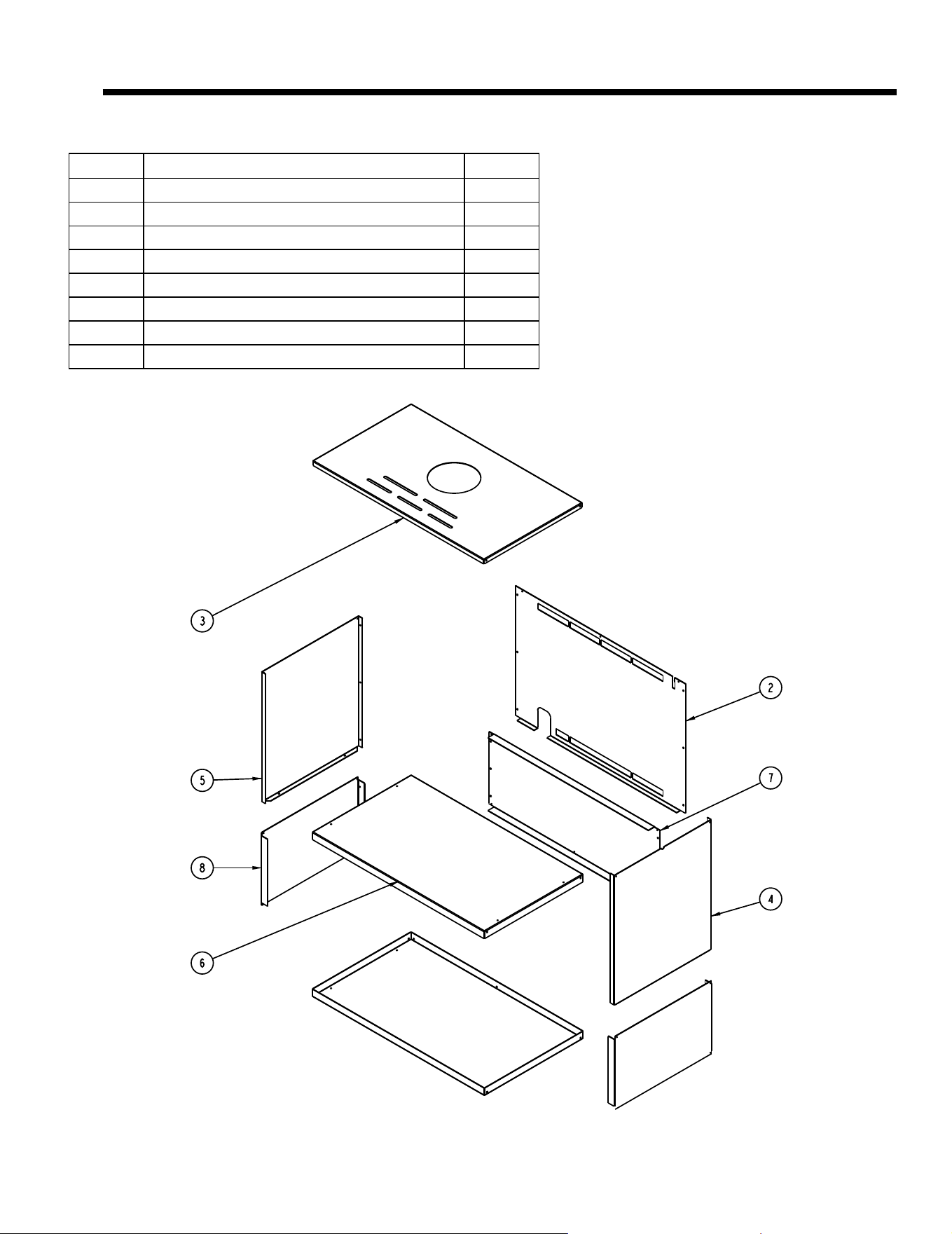
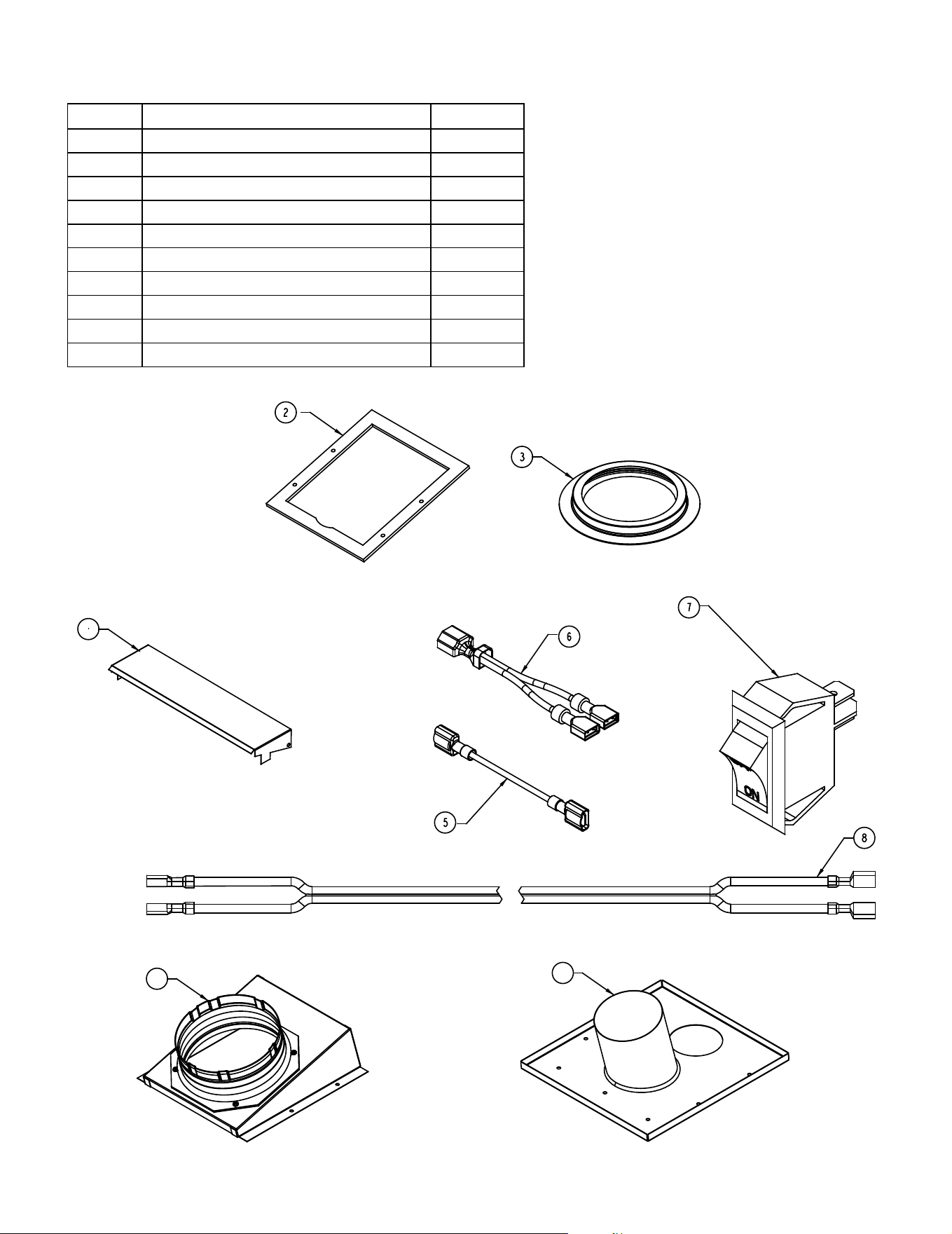
B. Kit Contents CK-30
Item DESCRIPTION QTY
1 FASTENER PACK 37 (#8X1/2” SCREWS) 1
2 CASE BACK ASSEMBLY 1
3 CASE TOP 1
4 CASE RH SIDE 1
5 CASE LH SIDE 1
6 BASE TOP/BOTTOM 2
7 BASE BACK 1
8 BASE SIDE 2
Hearth & Home Technologies • CK-30 Cabinet Kit Installation Manual • 4126-900 Rev D • 2/244
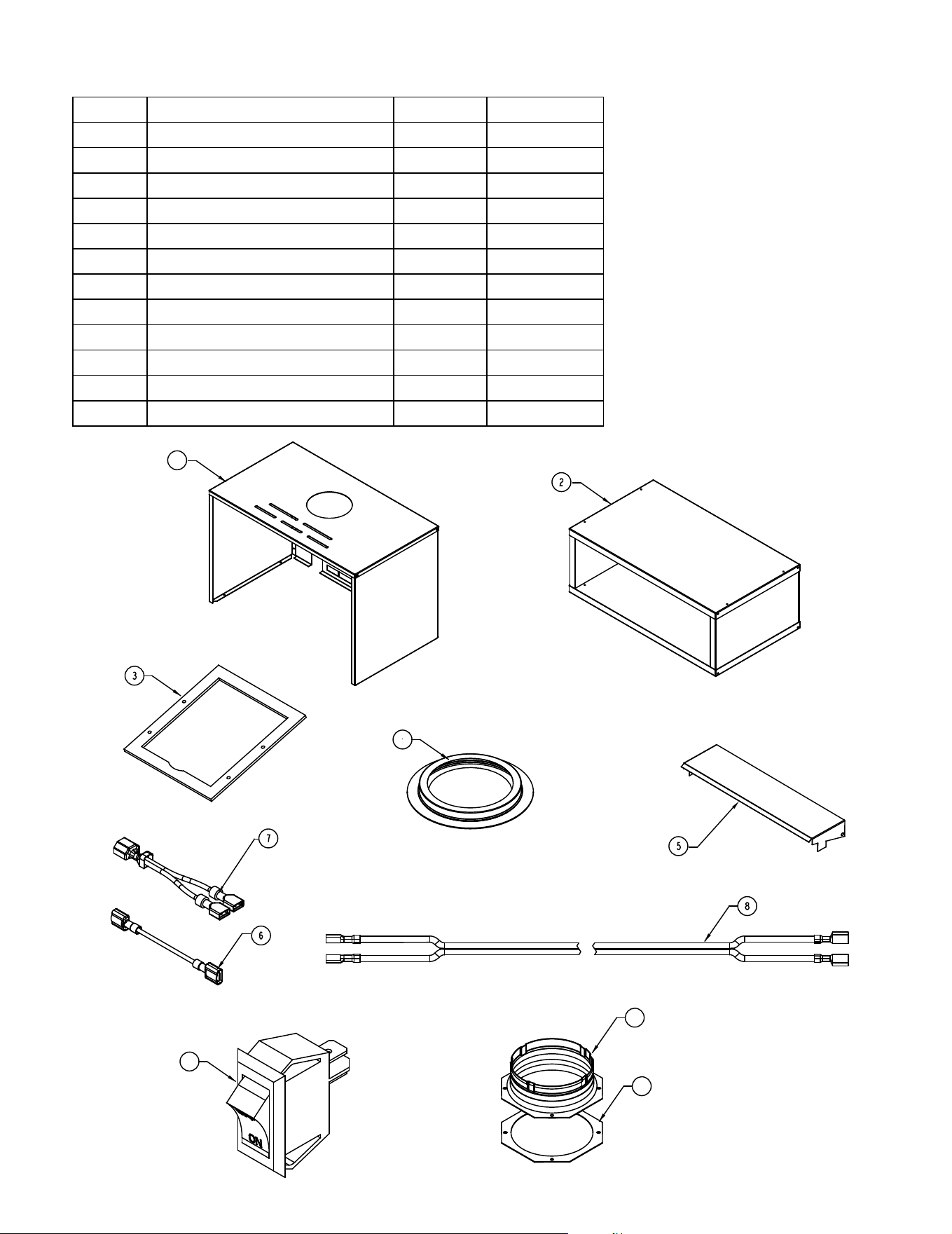
Item DESCRIPTION QTY
1 FASTENER PACK 7 (#8X3/4” SCREWS) 1
2 GASKET, ADAPTER 1
3 TRIM RING ASSEMBLY 1
4 ADAPTER SHIELD 1
5 2” JUMPER WIRE 1
6 JUMPER WIRE 1
7 ROCKER SWITCH 1
8 WIRE 1
9 ADAPTER ASSEMBLY 1
10 ADAPTER WELDMENT 1
C. Kit Contents ADP-CK30
4
9
10
Hearth & Home Technologies • CK-30 Cabinet Kit Installation Manual • 4126-900 Rev D • 2/245
D. Replacement Parts CK-30 and ADP-CK30
ITEM DESCRIPTION COMMENTS PART NUMBER
1 TOP CABINET ASSEMBLY SRV4126-008
2 BOTTOM CABINET ASSEMBLY SRV4126-009
3 GASKET, ADAPTER SRV4126-120
4 TRIM RING ASSEMBLY SRV4126-005
5 ADAPTER SHIELD SRV4126-121
6 2” JUMPER WIRE SRV2012-206
7 JUMPER WIRE SRV2187-198
8 WIRE W/1/4 STR TERM M/F SRV30007499
9 ROCKER SWITCH SRV32D0232
10 ASSEMBLY, STARTING COLLAR SRV2189-002
11 ADAPTER GASKET 460-0610
NS POWDER COAT TOUCH UP PAINT 71479
4
9
1
10
11
Hearth & Home Technologies • CK-30 Cabinet Kit Installation Manual • 4126-900 Rev D • 2/246
2 2
Getting Started
A. Design and Installation Considerations
This appliance may only terminate vertically, horizontal
termination is not allowed. Hearth & Home Technologies
direct vent gas appliances are designed to operate with all
combustion air siphoned from outside of the building and
all exhaust gases expelled to the outside. No additional
outside air source is required.
Installation MUST comply with local, regional, state and
national codes and regulations. Consult insurance carrier,
local building inspector, re ocials or authorities having
jurisdiction over restrictions, installation inspection and
permits.
Before installing, determine the following:
• Where the appliance is to be installed.
• The vent system conguration to be used.
• Gas supply piping requirements.
• Electrical wiring requirements.
• Whether optional accessories—devices such as a fan or
remote control—are desired.
C. Inspect Appliance and Components
• Carefully remove the appliance and components from the
packaging.
• The vent system components and optional accessories
may be shipped in separate packages.
• If packaged separately, the log set must be installed.
• Report to your dealer any parts damaged in shipment,
particularly the condition of the glass.
• Read all of the instructions before starting the
installation. Follow these instructions carefully during
the installation to ensure maximum safety and benet.
WARNING! Risk of Fire or Explosion! Damaged parts
could impair safe operation. DO NOT install damaged,
incomplete or substitute components. Keep appliance dry.
B. Tools and Supplies Needed
Before beginning the installation be sure that the following
tools and building supplies are available.
Tape measure Framing material
Pliers Hammer
Phillips screwdriver Manometer
Gloves Framing square
Voltmeter Electric drill and bits (1/4 in.)
Plumb line Safety glasses
Level Reciprocating saw
Flat blade screwdriver
Non-corrosive leak check solution
1/2 - 3/4 in. length, #6 or #8 Self-drilling screws
Caulking material (300ºF minimum continuous exposure
rating)
One 1/4 in. female connection (for optional fan).
WARNING! Risk of Fire, Explosion or Electric Shock! DO
NOT use this appliance if any part has been under water.
Call a qualied service technician to inspect the appliance
and to replace any part of the control system and/or gas
control which has been under water.
Improper installation, adjustment, alteration, service or
maintenance can cause injury or property damage. For
assistance or additional information, consult a qualied service
technician, service agency or your dealer.
Hearth & Home Technologies disclaims any responsibility for,
and the warranty will be voided by, the following actions:
• Installation and use of any damaged appliance or vent system
component.
• Modication of the appliance or vent system.
• Installation other than as instructed by Hearth & Home
Technologies.
• Improper positioning of the gas logs or the glass door.
• Installation and/or use of any component part not approved
by Hearth & Home Technologies.
Any such action may cause a re hazard.
Installation and service of this appliance should be
performed by qualied personnel. Hearth & Home
Technologies suggests NFI certied or factory trained
professionals, or technicians supervised by an NFI
certied professional (www.ncertied.org).
Installation and service of this appliance should be performed by
qualied personnel. Hearth & Home Technologies recommends
HHT Factory Trained or NFI certied professionals.
Hearth & Home Technologies • CK-30 Cabinet Kit Installation Manual • 4126-900 Rev D • 2/247
3 3
Framing and Clearances
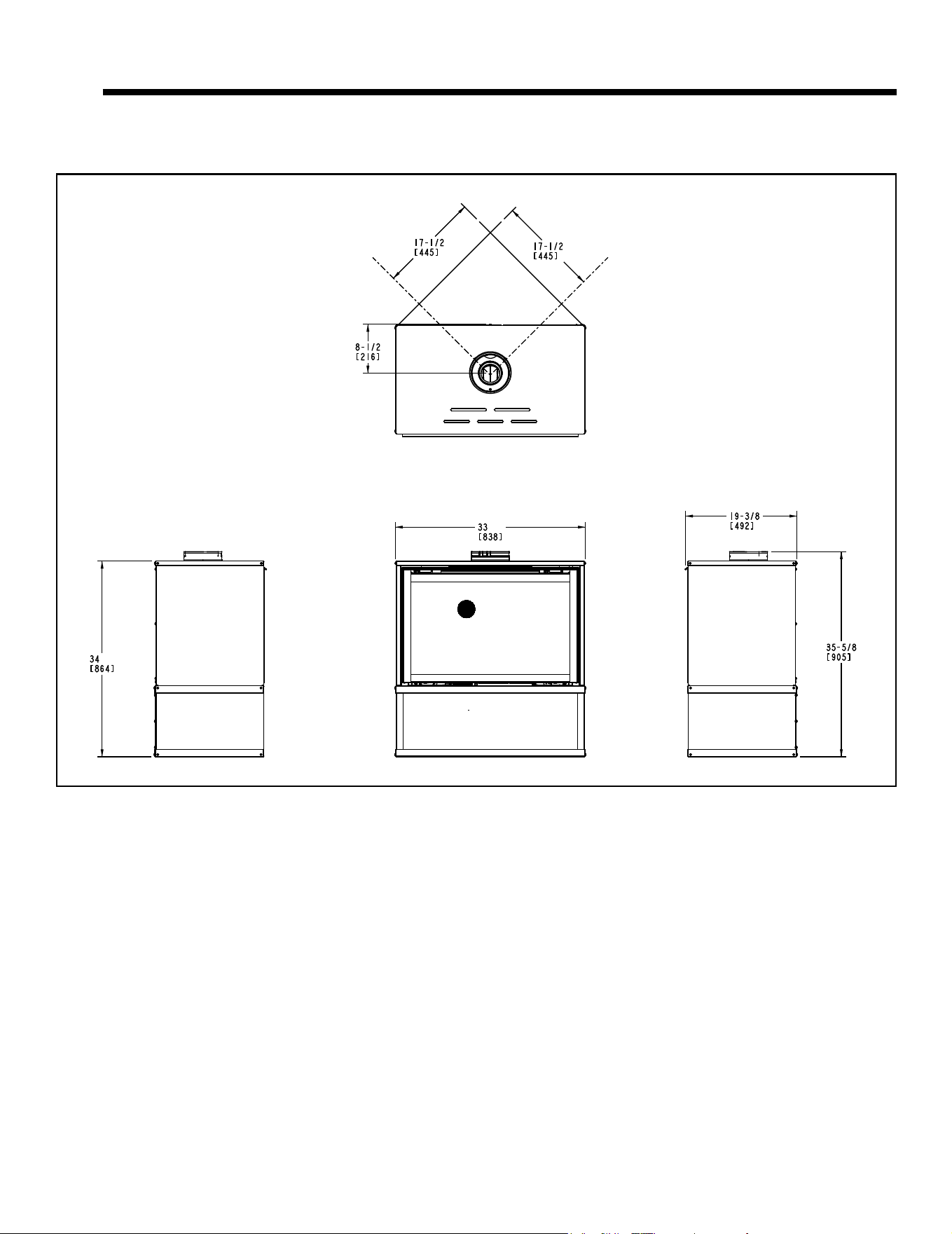
A. Appliance Dimension Diagram
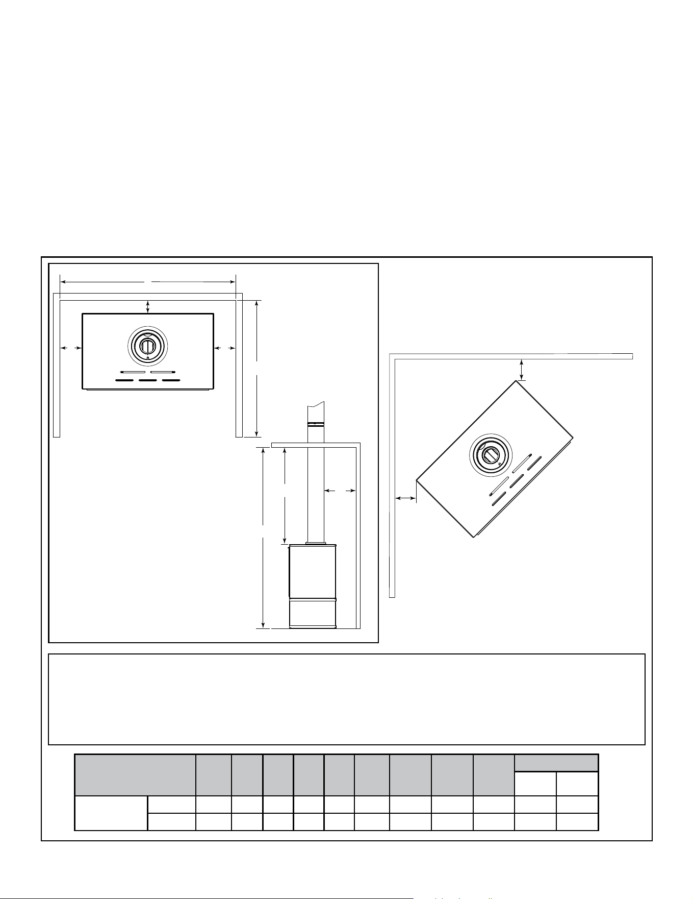
Dimensions are actual appliance dimensions. Use for reference only.
Figure 3.1 - Appliance Dimensions
NOTE: Actual vent collar
location may change slightly
based on cabinet install.
Hearth & Home Technologies • CK-30 Cabinet Kit Installation Manual • 4126-900 Rev D • 2/248
B. Clearances to Combustibles
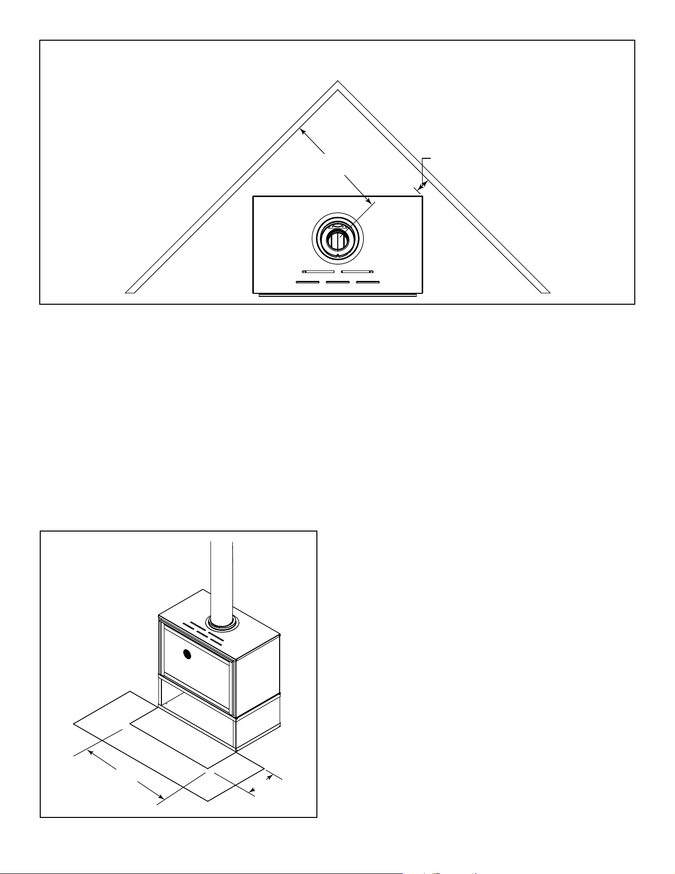
When selecting a location for the appliance it is important to
consider the required clearances to walls (see Figure 3.2).
WARNING! Risk of Fire or Burns! Provide adequate
clearance around air openings and for service access. Due
to high temperatures, the appliance should be located out of
trac and away from furniture and draperies.
NOTICE: Illustrations reect typical installations and are FOR
DESIGN PURPOSES ONLY. Illustrations/diagrams are not
drawn to scale. Actual installation may vary due to individual
design preference.
NOTICE: Some carpet materials may be sensitive to radiant
heat from the appliance causing discoloration or odor.
Figure 3.2 - Appliance Locations
Model A B *B C *C D
E
(MAX.)
F G
H
Top of
pipe
Side of
pipe
CK-30
Inches
5-1/2 5 8 3 5 75 36 44 40 3 1
Millimeters
140 127 203 76 127 1905 914 1118 1016 76 25
C. Hearth Extension/Floor Protection
CAUTION! Risk of Fire or Injury! Install appliance on
a stable, level, platform or oor strong enough to support
appliance without tipping.
A non-combustible hearth pad is not required. However,
the floor beneath the appliance must be stable, level, and
strong enough to support the appliance without a tipping
hazard. It is permissible to place the appliance on carpet.
Combustible flooring may be located in front of the appliance.
See Figure 3.4 for vinyl flooring recommendations.
Alcove Installation
Note: Dimensions are minimums as shown and may not be typical for all applications. An alcove installation is
shown above on left.
*To remove the fan from the back of the appliance clearance to the wall should be increased to *B and *C to allow
back panel of the cabinet to be removed. The fan may be removed from front of appliance. See Insert Installation
Manual.
G
D
H
A
B or *B
E (Max)
A
F
C or *C
C or *C
Hearth & Home Technologies • CK-30 Cabinet Kit Installation Manual • 4126-900 Rev D • 2/249
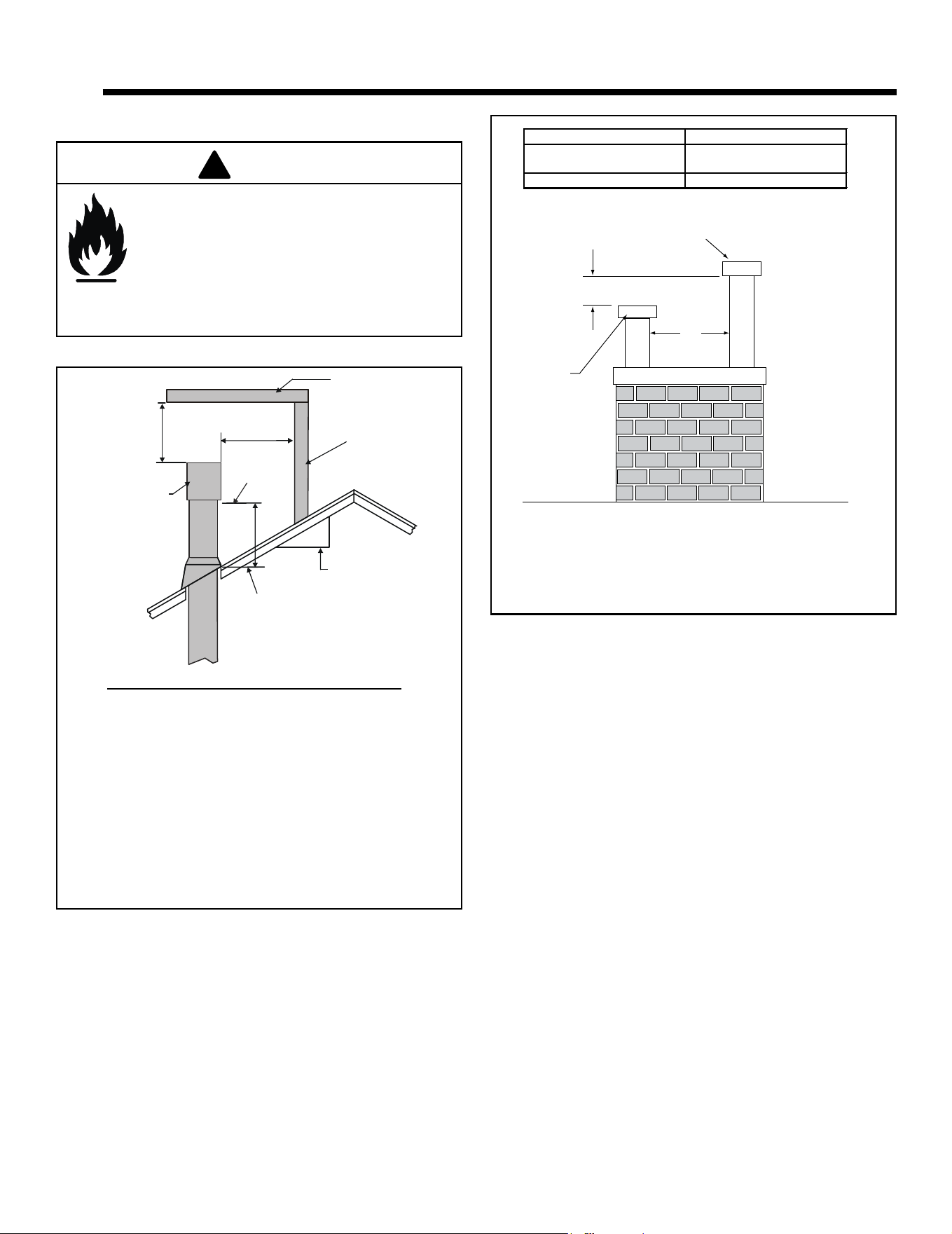
Vinyl Flooring
Vinyl Flooring is sensitive to heat. A 12 inch minimum
depth hearth extension is recommended when using vinyl
ooring up to the applicance. See Figure 3.4.
NOTICE: Clearances that do not meet the minimum
guidelines could result in damage or buckling to the vinyl
ooring and is done at the installer’s risk.
Hearth and Home Technologies does not recommend
adhesive based vinyl ooring due to thermal expansion.
Floating-style ooring can be used, but will reach
temperatures up to 110°F in a room with ambient
temperature of 70°F. Consult ooring specications to
ensure compatibility.
Figure 3.4 - Vinyl Flooring Requirements
Vinyl Flooring
Appliance width min
12 in. min
Corner Installation - Measurement
from center of ue to wall
Figure 3.3
20-3/4 in
527 mm
3 in
76 mm
Hearth & Home Technologies • CK-30 Cabinet Kit Installation Manual • 4126-900 Rev D • 2/2410
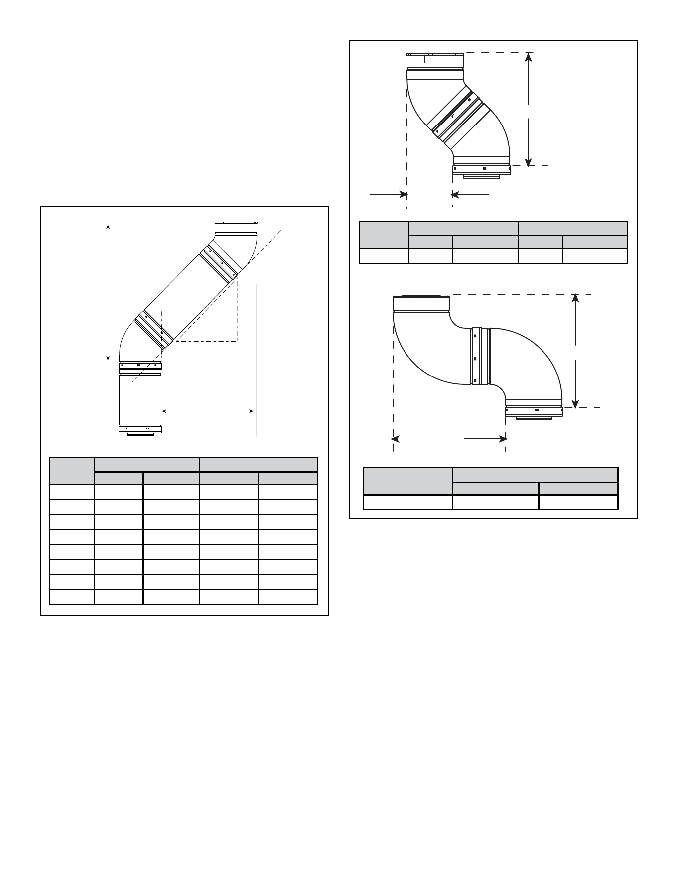
A. Vent Termination Minimum Clearances
Roof Pitch H (Min.) Ft.
Flat to 6/12...........................................................1.0*
Over 6/12 to 7/12 .................................................1.25*
Over 7/12 to 8/12 .................................................1.5*
Over 8/12 to 9/12 .................................................2.0*
Over 9/12 to 10/12 ...............................................2.5*
Over 10/12 to 11/12 .............................................3.25
Over 11/12 to 12/12 .............................................4.0
Over 12/12 to 14/12 .............................................5.0
Over 14/12 to 16/12 .............................................6.0
Over 16/12 to 18/12 .............................................7.0
Over 18/12 to 20/12 .............................................7.5
Over 20/12 to 21/12 .............................................8.0
Figure 4.1- Minimum Height From Roof To Lowest Discharge Opening
HORIZONTAL
OVERHANG
VERTICAL
WALL
GAS DIRECT VENT
TERMINATION CAP
12
X
ROOF PITCH
IS X/ 12
LOWEST
DISCHARGE
OPENING
2 FT.
MIN.
20 INCHES MIN.
H (MIN.) - MINIMUM HEIGHT FROM ROOF
TO LOWEST DISCHARGE OPENING
4 4
Termination Location and Vent Information
Fire Risk.
Maintain vent clearance to combustibles as
specied.
• DO NOT pack air space with insulation or other
materials.
Failure to keep insulation or other materials away
from vent pipe may cause overheating and re.
Figure 4.2 - Staggered Termination Caps
Gas, Wood or Fuel Oil
Termination Cap
B
Gas
Termination
Cap **
A *
*
If using decorative cap cover(s), this distance may need to be
increased. Refer to the installation instructions supplied with the
decorative cap cover.
**
A B
6 in. (minimum) up to 20 in.
152 mm/508 mm
18 in. minimum
457 mm
20 in. and over 0 in. minimum
In a staggered installation with both gas and wood or fuel oil
terminations, the wood or fuel oil termination cap must be
higher than the gas termination cap.
WARNING
!

Hearth & Home Technologies • CK-30 Cabinet Kit Installation Manual • 4126-900 Rev D • 2/2411
B. Approved Pipe
This appliance is approved for use with Hearth & Home
Technologies SLP, Simpson Duravent and ICC venting
systems. Refer to Section 11.A for vent component
information and dimensions.
DO NOT mix pipe, ttings or joining methods from dierent
manufacturers.
The pipe is tested to be run inside an enclosed wall. There
is no requirement for inspection openings at each joint
within the wall.
WARNING! Risk of Fire or Asphyxiation. This appliance
requires a separate vent. DO NOT vent to a pipe serving a
separate solid fuel burning appliance.
DO NOT USE FIELD-FABRICATED VENTING
COMPONENTS.
This product is approved to be vented vertically through the
roof. You may vent through a Class A or masonry chimney if
an approved adapter is used. This product is not approved
for use with a horizontal termination.
This appliance is a direct vent heater. All combustion air must
come directly from the outside of the building. The vent pipe
for this unit consists of an inner and an outer pipe. The inner
pipe carries the appliance exhaust out of the system, and
the outer pipe brings fresh combustion air into the appliance.
• A round support box/wall thimble or heat shield is required
when the venting passes through a combustible wall.
• A support box or ceiling restop is required when the
venting passes through a ceiling.
• Roof ashing and a storm collar are required when venting
passes through the roof.
• Follow instructions provided with the venting for installation
of these items.
Hearth & Home Technologies • CK-30 Cabinet Kit Installation Manual • 4126-900 Rev D • 2/2412
C. Use of Elbows
Diagonal runs have both vertical and horizontal vent aspects
when calculating the eects. Use the rise for the vertical
aspect and the run for the horizontal aspect. See Figure 4.4.
Two 45º elbows may be used in place of one 90º elbow. On
45º runs, one foot of diagonal is equal to 8-1/2 in. (216 mm)
horizontal run and 8-1/2 in. (216 mm) vertical run. A length
of straight pipe is allowed between two 45º elbows. See
Figure 4.4.
Figure 4.5 shows the vertical and horizontal osets for SLP
elbows.
Figure 4.4
HORIZONTAL
VERTICAL
RUN
RISE
EFFECTIVE
LENGTH
Y
X
X
X
Vent Type
X
Inches Millimeters
SLP 11-1/4 286
Vent
Type
X Y
Inches Millimeters Inches Millimeters
SLP 5 127 11-3/4 298
SLP
Pipe
Eective Length Rise/Run
Inches Millimeters Inches Millimeters
SLP4 4 102 2-3/4 70
SLP6 6 152 4-1/4 108
SLP12 12 305 8-1/2 216
SLP24 24 610 17 432
SLP36 36 914 25-1/2 648
SLP48 48 1219 34 864
SLP6A 3 to 6 76 to 152
2-1/8-4-1/4 54-108
SLP12A 3 to 12 76 to 305
2-1/8-8-1/2 54-216
Figure 4.5 - Vertical and Horizontal Oset for SLP Elbows
D. Measuring Standards
Vertical and horizontal measurements listed in the vent
diagrams were made using the following standards:
• Pipe measurements are shown using the eective length of
pipe. See Figure 11.1 for SLP for information on eective
length of pipe components.
• Vertical terminations are measured to bottom of
termination cap.
• Horizontal pipe installed level with 1/4 inch rise per foot.
Y
X
X
X

Hearth & Home Technologies • CK-30 Cabinet Kit Installation Manual • 4126-900 Rev D • 2/2413
F. Vent Diagrams
General Rules:
• SUBTRACT 3 ft. from the total H measurement for each
90º elbow installed horizontally.
• SUBTRACT 1 ft. from the total H measurement for each
45º elbow installed horizontally.
• A maximum of three 90º elbows (or six 45º elbows) may
be used in any vent conguration. Some elbows may be
installed horizontally. See specic vent diagrams.
• When penetrating a combustible wall, a wall shield restop
must be installed.
• When penetrating a combustible ceiling, a ceiling restop
must be installed.
E. Venting Guidelines for Horizontal Runs
Max Horizontal Run 2 ft. (50 mm) when vertical
rise is 10 ft (3m)
Min Vertical Before
Elbow
Min of 4 ft vertical (102 mm)
must be used prior to any
horizontal run.
Horizontal Run requires a non-combustible support
every 5 ft (1.5 m), i.e., plumbing tape
A vent run o the top of the appliance must have a
minimum vertical of 4 feet.
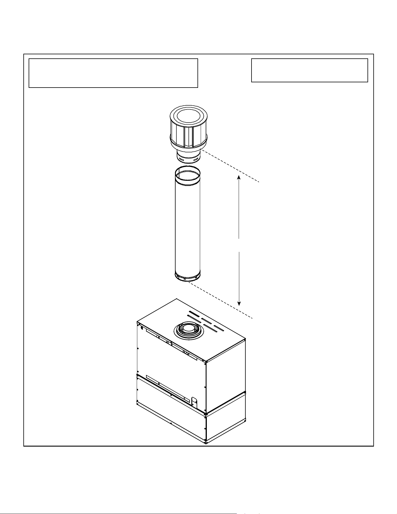
Hearth & Home Technologies • CK-30 Cabinet Kit Installation Manual • 4126-900 Rev D • 2/2414
Figure 4.6
V
1
V
1
= 40 ft. Max. (12.2 m)
V
1
= 10 ft. Min. (3.0 m)
Note: As vertical pipe increases, vertical restrictors will need
to be adjusted. See Insert installation manual for adjustment
instructions.
Top Vent - Vertical Termination - (continued)
No Elbow
Hearth & Home Technologies • CK-30 Cabinet Kit Installation Manual • 4126-900 Rev D • 2/2415
Top Vent - Vertical Termination - (continued)
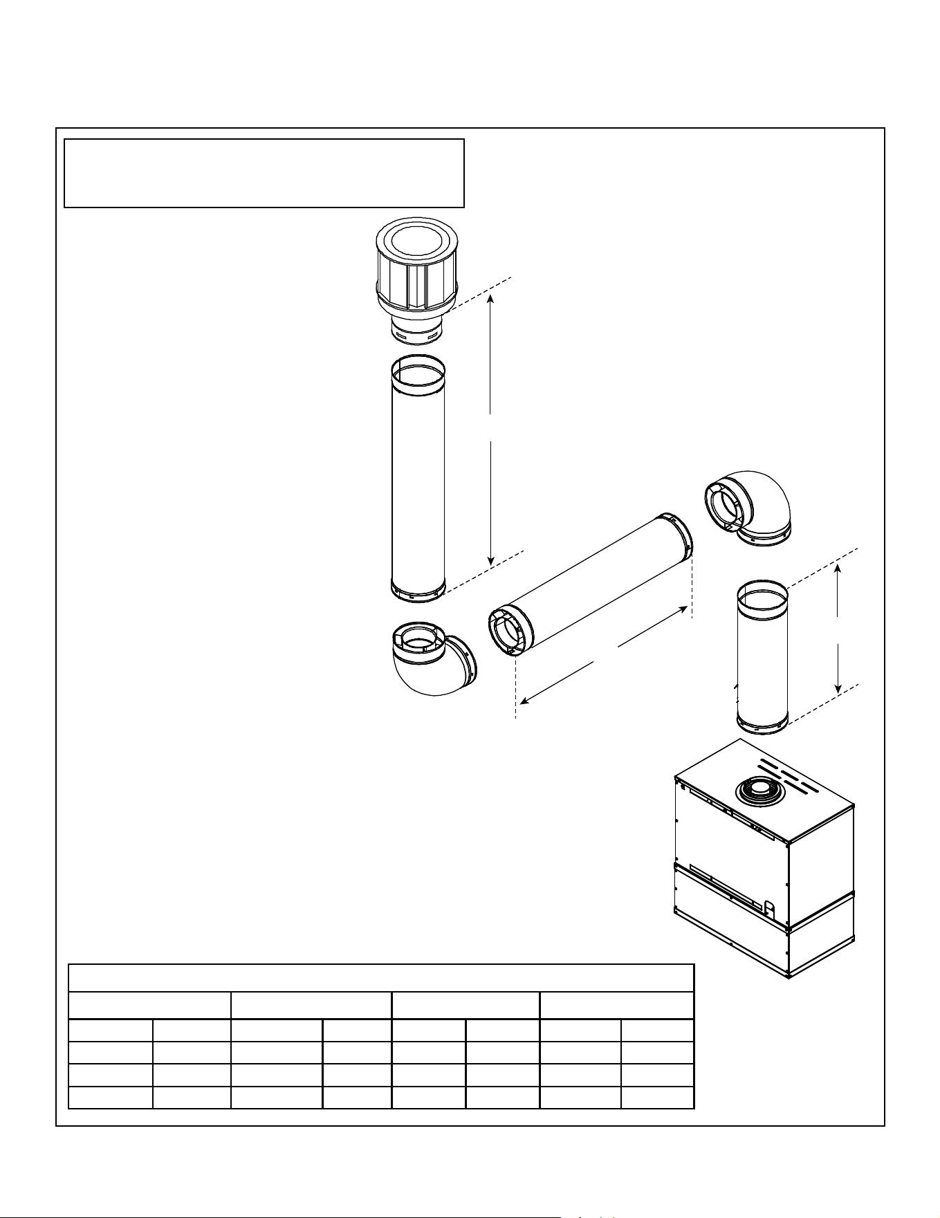
Two Elbows
Figure 4.7
H
1
V
1
V
2
2 Elbows to Max. Horizontal
V
1
Minimum V
1
+ V
2
Maximum V
1
+ V
2
Minimum H
1
Maximum
4 ft. 1.2 m 24 ft. 7.3 m 10 ft. 3.1 m 2 ft. 610 mm
10 ft. 3.1 m 15 ft. 4.6 m 10 ft. 3.1 m 2 ft. 610 mm
20 ft. 6.1 m 24 ft. 7.5 m 20 ft. 6.1 m 2 ft. 610 mm
28 ft. 8.5 m 34 ft. 9.1 m 28 ft. 8.5 m 3 ft. 914 mm
Note: As vertical pipe increases, vertical restrictors will need
to be adjusted. See Insert installation manual for adjustment
instructions.
Hearth & Home Technologies • CK-30 Cabinet Kit Installation Manual • 4126-900 Rev D • 2/2416
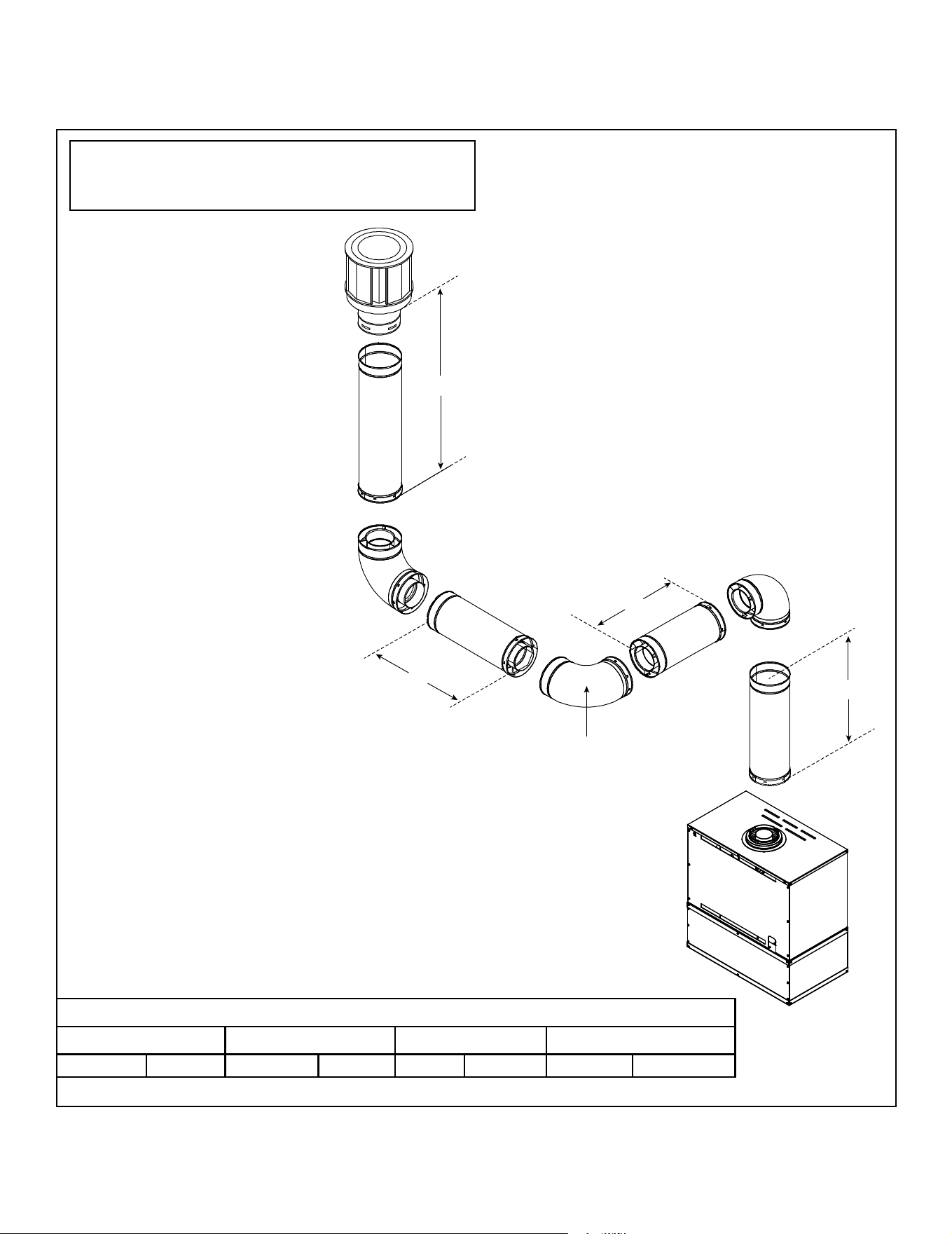
Figure 4.8
Top Vent - Vertical Termination - (continued)
Three Elbows
INSTALLED
HORIZONTALLY
H
1
H
2
V
1
V
2
3 Elbows to Max. Horizontal
V
1
Minimum V
1
+ V
2
Maximum V
1
+ V
2
Minimum H
1
+ H
2
Maximum
8 ft. 2.4 m 34 ft. 9.1 m 28 ft. 8.5 m 1 ft. 310 mm
Note: As vertical pipe increases, vertical restrictors will need
to be adjusted. See Insert installation manual for adjustment
instructions.
Hearth & Home Technologies • CK-30 Cabinet Kit Installation Manual • 4126-900 Rev D • 2/2417
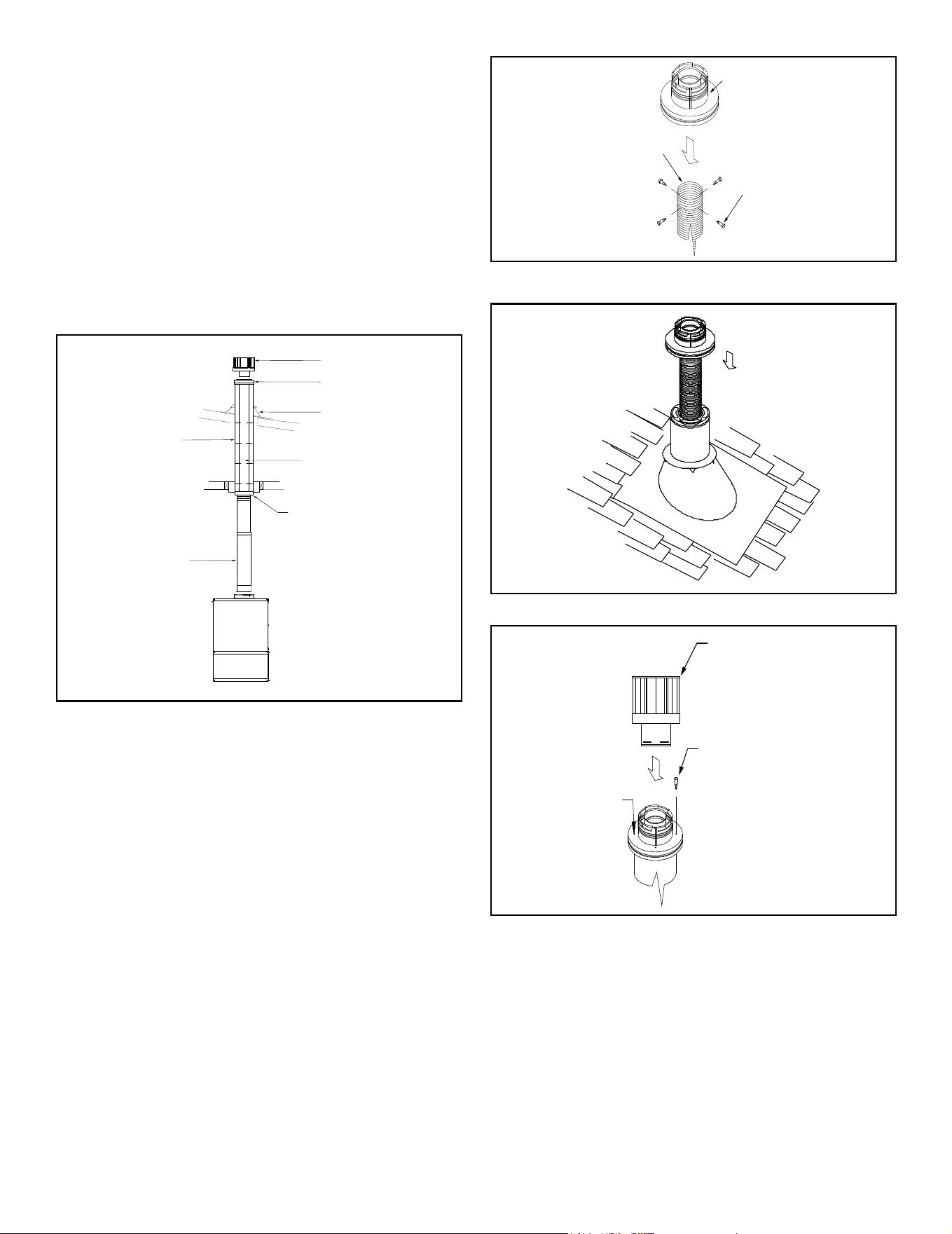
TERMINATION CAP
(Includ. in Link-Stove Kit)
EXISTING METAL
CHIMNEY SYSTEM
TOP ADAPTOR
(Includ. in Link-Stove Kit)
DIRECT VENT PIPE
(Length as required)
FLASHING
(Includ. in Link-Stove Kit)
4 in. (102mm) FLEX PIPE
(Includ. in Link-Stove Kit)
RETRO CONNECTOR
(Includ. in Link-Stove Kit)
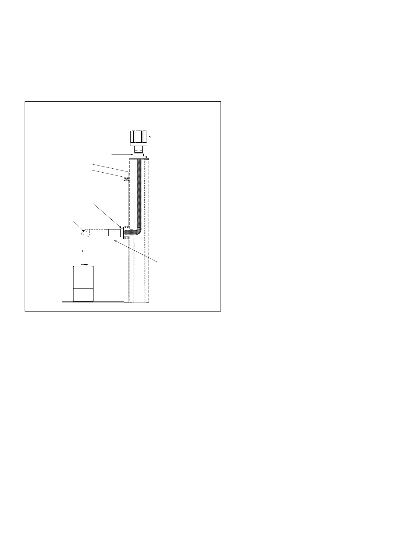
Class A Metal Chimney
Prior to installing the gas stove, ensure that the existing
chimney is functionally sound and clean.
• Have the chimney and adjacent structure inspected
and cleaned by qualied professionals. Hearth & Home
Technologies recommends that NFI or CSIA certied
professionals, or technicians under the direction of
certied professionals, conduct a minimum of a NFPA
211 Level 2 inspection of the chimney.
• Replace component parts of the chimney and replace
as specied by the professionals.
• See Section 11 for venting components.
High Wind Termination Cap
(Part SLP-TVHW)
Sheet Metal Screws
Drill Four 1/8 in.
(3mm) Diamater
Holes
Figure 4.11
Figure 4.12
5. Pull the flex pipe down through the ceiling support box,
until it protrudes approximately 3 in. (76mm). Connect
the flex pipe to the retro connector, and attach with sheet
metal screws.
6. Push the flex pipe back up into the ceiling support box,
center the retro connector, and attach it to the support
box with sheet metal screws.
7. The connection between the appliance and the retro
connector may be completed with sections of direct vent
pipe.
Top Adapter
(Included in Link-Stove Kit)
Sheet Metal Screws
4” Flex Pipe
(Included in Link-Stove Kit)
Figure 4.10
Figure 4.9
1. Remove existing chimney cap.
2. Measure the distance from the top of the chimney to the
bottom of the ceiling support box, add 3 in. (76mm) to
this measurement, and cut a section of 4 in. (101mm)
flex pipe to that length (the flex should be fully extended).
3. Connect the end of the flex pipe section to the underside
of the top adapter, using four sheet metal screws. See
Figure 4.10.
4. Pass the flex pipe down through the center of the
chimney system, and center the top adapter on the top
of the chimney pipe. Drill four 1/8 in. (3mm) diameter
holes through the top adapter, and into the chimney
top. Ensure that you are drilling into the metal on the
chimney. Twist lock the high wind termination cap onto
the top adapter. See Figure 4.11 and Figure 4.12.
Hearth & Home Technologies • CK-30 Cabinet Kit Installation Manual • 4126-900 Rev D • 2/2418
Existing Masonry Chimney
Prior to installing the gas stove, ensure that the existing chimney is functionally sound and clean.
• Have the chimney and adjacent structure inspected and cleaned by qualied professionals. Hearth & Home Technologies
recommends that NFI or CSIA certied professionals, or technicians under the direction of certied professionals, conduct
a minimum of a NFPA 211 Level 2 inspection of the chimney.
• Replace component parts of the chimney and replace as specied by the professionals.
• See Section 10 for venting components.
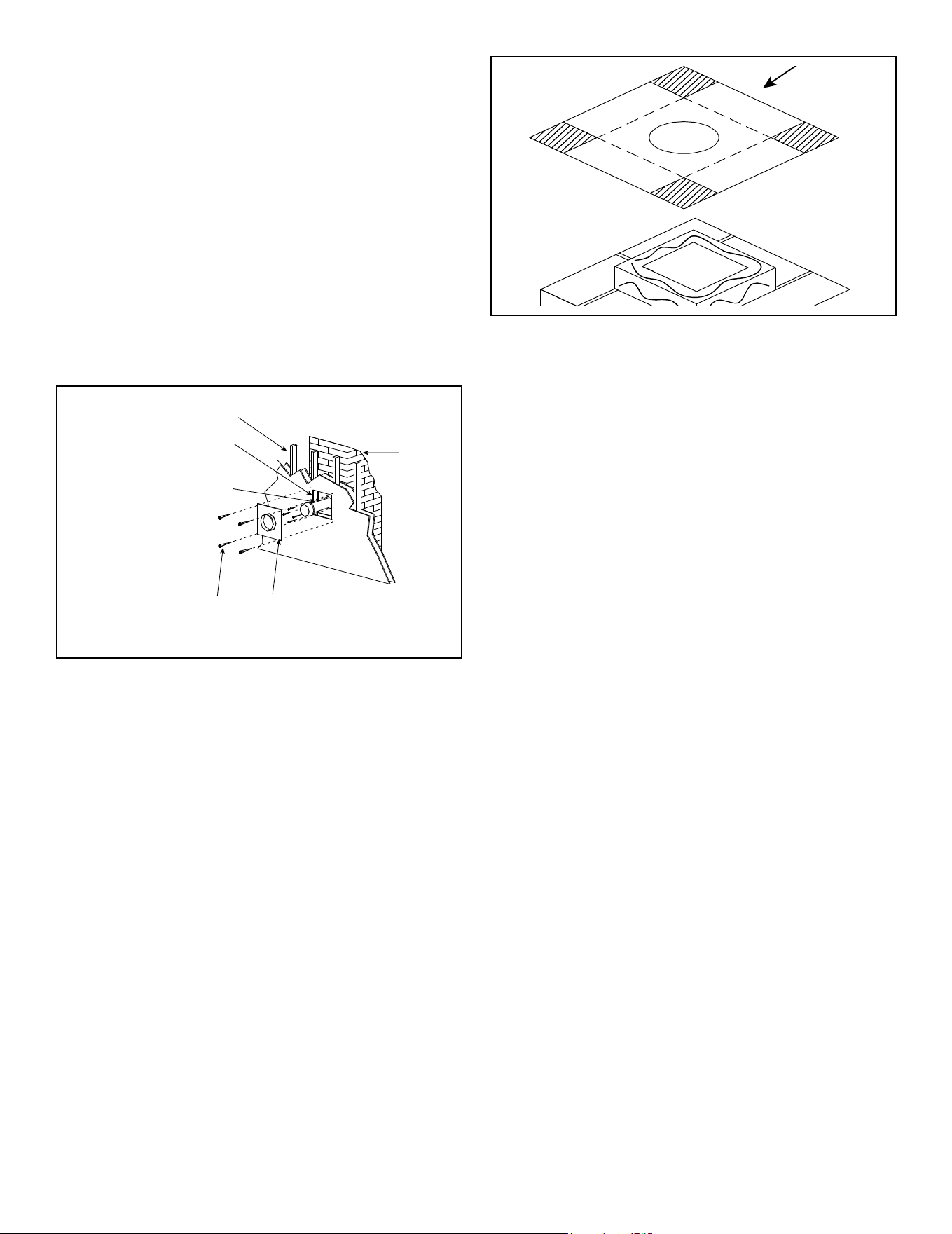
Type C - Up & Out Installation
Figure 4.13
TERMINATION CAP
(Included in LINK-STOVE Kit)
FLASHING
(Included in Masonry
Chimney Conversion Kit &
LINK-STOVE Kit)
4 in. (102mm) FLEX LINER
(Included in LINK-STOVE Kit)
TOP ADAPTOR
(Included in Masonry Chimney
Conversion Kit & LINK-STOVE Kit)
RETRO CONNECTOR
(Included in Masonry Chimney
Conversion Kit & LINK-STOVE Kit)
90° ELBOW
DIRECT VENT PIPE
(Length as required)
2 ft. maximum
horizontal run
Hearth & Home Technologies • CK-30 Cabinet Kit Installation Manual • 4126-900 Rev D • 2/2419
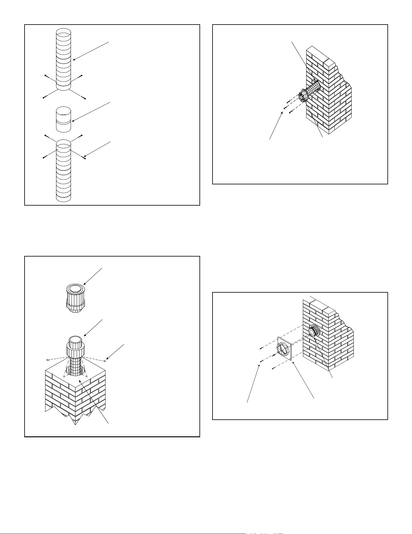
10 in. x 10 in. (254mm x 254mm)
framed opening in wall
Studwall
Masonry
Chimney
Retro Connector
(Included in Masonry Chimney
Conversion Kit)
(4) Masonry Bolts
(Not Included)
Wall Thimble Cover
(Included in Masonry
Chimney Conversion Kit)
Cut and bend flashing as needed
to fit
Sealant adhesive
1. Before cutting any holes, assemble the desired sections
of direct vent pipe to determine the center of the masonry
penetration.
2. Once the center point of the penetration has been
determined, cut a 6 in. (152mm) diameter hole in the
masonry. If the hole is too large, the retro connector
might not mount properly; if the hole is too small, the
appliance might starve for intake air. If there is a frame
wall in front of the masonry wall, cut and frame a 10 in.
(254mm) square opening in the wall (centered around
the 6 in. (152mm) masonry opening). If there is sheet
rock only (no studs) in front of the masonry the 10 in.
(254mm) opening is still needed, but does not need to be
framed. If the hole is framed a wall thimble is required.
This allows the retro connector to mount directly on
the masonry and provide the correct clearances to
combustibles. See Figure 4.14.
Figure 4.15
4. To determine the length of flex needed, measure from
3 in. (76mm) above the top of the flashing down to the
level of the opening. Add the distance from the center
of the chimney out through the wall. Cut a piece of 4
in. (102mm) flex to this length (extended to its nominal
length). Be sure to leave 2-3 in. (51-76mm) of flex above
the existing chimney to allow for connection to the
termination kit.
5. Connect the flex liner to the top adapter using three
sheet metal screws. See Figure 4.10.
6. Feed the flex liner through the flashing into the chimney.
Carefully feed the flex liner down the chimney to the
bottom and out the opening in the masonry wall, forming
an angle to line up the flex liner with the vent opening on
the appliance.
WARNING! Risk of Fire, Explosion or Asphyxiation!
Improper support may allow vent to sag and separate. Use
vent run supports and connect vent sections per installation
instructions. DO NOT allow vent to sag below connection
point to appliance.
7. If additional lengths of flex liner are needed to span the
chimney height, use a flex coupler to connect the pieces
of flex liner together. Connect the flex to the coupler by
using four sheet metal screws for each side. See Figure
4.16.
Figure 4.14
3. Secure the flashing to the top of the masonry chimney
using a bead of non-hardening sealant-adhesive. If the
flashing is larger than the top of the chimney, cut and fold
flashing as needed to fit chimney. See Figure 4.15.
Hearth & Home Technologies • CK-30 Cabinet Kit Installation Manual • 4126-900 Rev D • 2/2420
High Wind Termination Cap
(Part SLP-TVHW)
Top Adaptor
(Included in Link-Stove Kit)
(3) Sheet Metal
Screws
Flashing
(Included in Link-Stove Kit)
Figure 4.17
9. Attach the flex to the retro connector. Use three sheet
metal screws to attach the flex liner to the connector.
Mount the retro connector to the masonry wall using
masonry bolts. See Figure 4.18. Redrill larger holes
on connector as needed. Be careful to ensure that the
connector is centered in the opening and the mounting
holes line up with the masonry wall.
6 in. (152mm) diameter
opening in masonry wall
(3) Masonry Bolts
(Not included)
Retro Connector
(Included in Masonry Chimney
Conversion Kit)
(4) Masonry Bolts
(Not included)
Retro Connector
(Included in Masonry
Chimney Conversion Kit)
Wall Thimble Cover
(Included in Masonry Chimney Conversion Kit)
Figure 4.16
8. Secure the top adapter to the flashing. Use three sheet
metal screws through the side of the top adapter into the
flange on the flashing See Figure 4.17. Twist lock the
high wind termination cap on to the top adapter.
Flex Liner
(3 in. Part 3DFA-35)
(4 in. Part 4DFA-35)
Flex Coupler
(3 in. Part 3DFA-FC)
(4 in. Part 4DFA-FC)
Sheet Metal Screws
Figure 4.19
Figure 4.18
10. Slide wall thimble cover over retro connector and secure
with masonry bolts. See Figure 4.19. If you have a
framed wall in front of the masonry, use wood screws
to mount wall thimble cover to framed wall, over retro
connector and 10 in. (254mm) square framed opening
See Figure 4.14. If needed, add a section of direct vent
pipe to the retro connector in order to extend through
the opening in the wall thimble cover.
11. The connection between the appliance and the retro
connector may be completed with sections of direct
vent pipe.
Hearth & Home Technologies • CK-30 Cabinet Kit Installation Manual • 4126-900 Rev D • 2/2421
A. Pipe Clearances to Combustibles
WARNING! Risk of Fire! Maintain air space clearance to
vent. DO NOT pack insulation or other combustibles:
• Between ceiling restops
• Between wall shield restops
• Around vent system
Failure to keep insulation or other material away from
vent pipe may cause overheating and re.
5 5
Vent Clearances and Framing
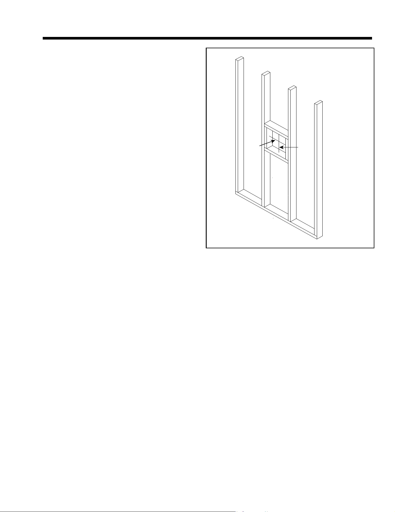
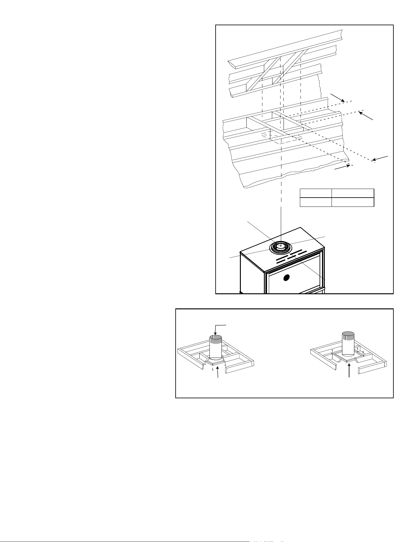
B. Wall Penetration Framing/Firestops
Combustible Wall Penetration
Whenever a combustible wall is penetrated, you must
frame a hole for the wall shield restop(s). The wall shield
restop maintains minimum clearances and prevents cold
air inltration.
• The opening must be framed on all four sides using the
same size framing materials as those used in the wall
construction.
• SLP pipe - A wall shield restop must be placed on each
side of an interior wall. A minimum 1-1/2 in. (38 mm)
overlap of attached heat shields must be maintained.
Non-Combustible Wall Penetration
If the hole being penetrated is surrounded by non-
combustible materials such as concrete, a hole with
diameter one inch greater than the pipe is acceptable.
Whenever a non-combustible wall is penetrated, the wall
shield restop is only required on one side and no heat
shield is necessary.
10 in.
10 in.
Figure 5.1 - Wall Penetration
Hearth & Home Technologies • CK-30 Cabinet Kit Installation Manual • 4126-900 Rev D • 2/2422
C. Ceiling Firestop/Floor Penetration Framing
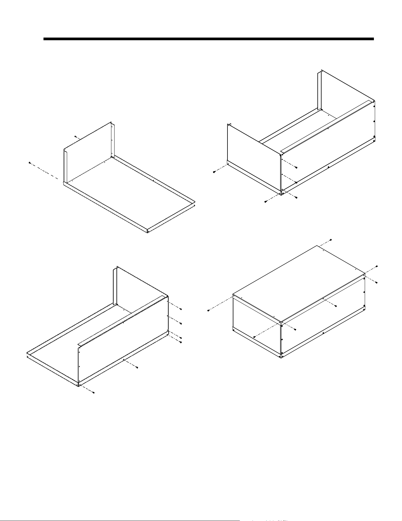
A ceiling restop MUST be used between oors and attics.
• SLP Pipe - Frame opening 9 in. x 9 in. (229 mm x 229 mm)
whenever the vent penetrates a ceiling/oor (see Figure
5.2).
• Frame the area with the same sized lumber as used in
ceiling/oor joist.
• The ceiling restop may be installed above or below the
ceiling joists when installed with an attic insulation shield. It
must be under joists between oors that are not insulated.
Refer to Figure 5.3.
• Secure with three fasteners on each side.
WARNING! Risk of Fire! DO NOT pack insulation around
the vent. Insulation must be kept back from the pipe to
prevent overheating.
D. Install Attic Insulation Shield
WARNING! Fire Risk. DO NOT allow loose materials or
insulation to touch vent. Hearth & Home Technologies
requires the use of an attic shield.
The International Fuel Gas Code requires an attic shield
constructed of 26 gauge minimum steel that extends at least
2 in. (51 mm) above insulation.
• Attic insulation shields must meet specied clearances to
combustible materials and be secured in place.
• An attic insulation shield kit is available from Hearth & Home
Technologies. Contact your dealer to order. Install attic
insulation shield according to instructions included with kit.
Figure 5.2 - Installing Ceiling Firestop
Figure 5.3 - Installing the Attic Shield
INSTALL ATTIC INSULATION SHIELDS
BEFORE OR AFTER INSTALLATION OF VENT SYSTEM
CEILING FIRESTOP
INSTALLED BELOW CEILING
CEILING FIRESTOP
INSTALLED ABOVE CEILING
ATTIC ABOVE
A
PIPE
SLP
A
9 in. (229 mm)
A
Hearth & Home Technologies • CK-30 Cabinet Kit Installation Manual • 4126-900 Rev D • 2/2423
6 6
Appliance Preparation
A. Assemble Cabinet
CAUTION! Risk of Cuts, Abrasions or Flying Debris.
Wear protective gloves and safety glasses during
installation. Sheet metal edges are sharp.
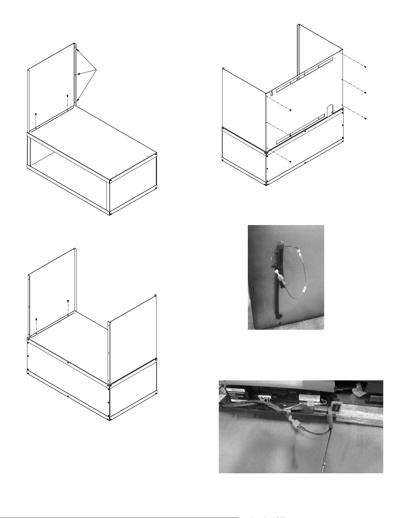
1. Assemble cabinet lower left side to cabinet base using 2
screws. See Figure 6.1.
Figure 6.1
2. Assemble cabinet lower back to cabinet lower left side
and cabinet base using 6 screws. See Figure 6.2.
Figure 6.2
Figure 6.3
4. Assemble cabinet lower top to cabinet lower sides and
cabinet lower back using 7 screws. See Figure 6.4.
Figure 6.4
3. Assemble cabinet lower right side to cabinet base and
cabinet lower back using 5 screws. See Figure 6.3.
-
-
-
-,
Cabinet Base
Cabinet Lower
Left Side
Cabinet Lower
Left Side
Cabinet Lower
Back
Cabinet Lower
Back
Cabinet Lower
Right Side
Cabinet Lower
Top
Hearth & Home Technologies • CK-30 Cabinet Kit Installation Manual • 4126-900 Rev D • 2/2424
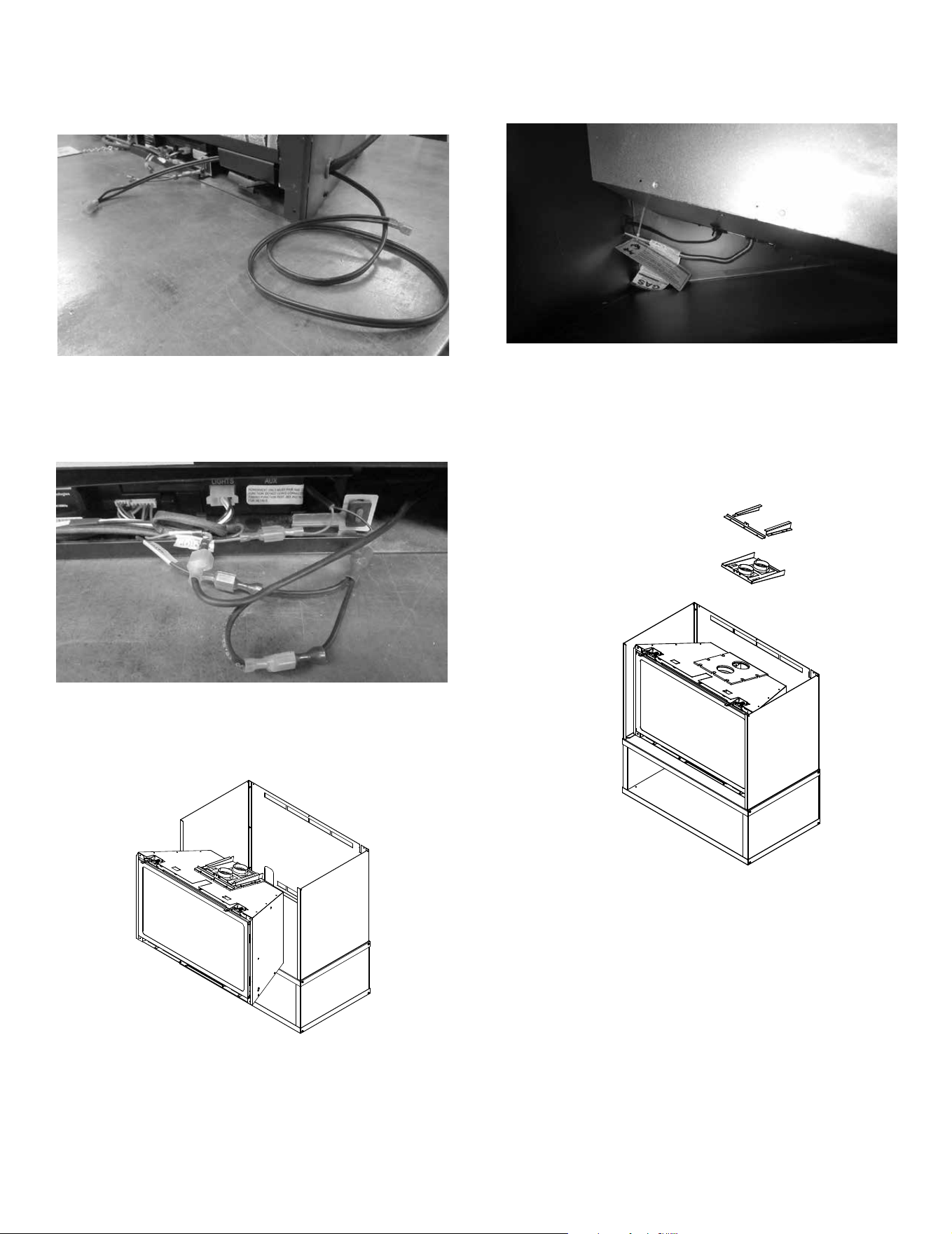
5. Assemble cabinet upper left side to cabinet lower top
using 2 screws. See Figure 6.5.
Figure 6.5
6. Assemble cabinet upper right side to cabinet lower top
using 2 screws. See Figure 6.6.
Figure 6.6
7. Assemble cabinet upper back to cabinet upper sides
using 6 screws. See Figure 6.7.
Figure 6.7
Cabinet Lower
Top
Cabinet Upper
Left Side
Note: Screw
holes in side
will be facing to
the back of the
cabinet.
Cabinet Upper
Left Side
Cabinet Upper
Right Side
Cabinet Upper
Back
8. Install the jumper wire on the reset switch wire on the
side of the insert. Leave the reset switch wire attached
to the side of the insert. See Figure 6.8.
Figure 6.8
9. Install the splitter (SRV2187-198) on the black wire
coming o the 6 pin wire harness on the IFT control.
Connect the splitter to the black wire going to the battery
pack USB port. See Figure 6.9.
Figure 6.9
Hearth & Home Technologies • CK-30 Cabinet Kit Installation Manual • 4126-900 Rev D • 2/2425
Figure 6.11
10. Insert the male connectors on the SRV30007499
wire through the grommet on the outer surround of the
insert. The male connectors go inside of the insert.
See Figure 6.10.
Figure 6.10
14. Remove slide plate guides, slide plate stop and slide
plate assembly by removing the 6 screws holding the
brackets to the top of the insert. See Figure 6.14.
11. Install the male connectors from wire (SRV30007499)
to the brown wire coming of the 6 pin wire harness on
the IFT control and to the splitter. See Figure 6.11.
Figure 6.12
Figure 6.14
13. Feed the exible gas line and power cord through the
slot on the lower left hand side of the cabinet back.
See Figure 6.13.
Figure 6.13
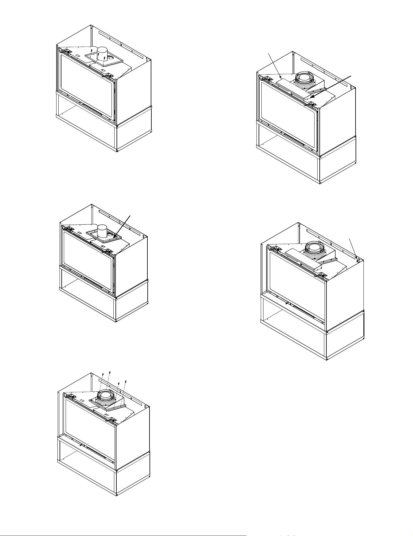
15. Inspect the slide plate gasket to make sure there are
no tears in the gasket. Install the adapter weldment
assembly to the top of the insert using the (3) #8 X
3/4” screws provided with the ADP-CK30 adapter kit.
See Figure 6.15.
12. Install insert into cabinet by setting on cabinet lower
top. See Figure 6.12.
Hearth & Home Technologies • CK-30 Cabinet Kit Installation Manual • 4126-900 Rev D • 2/2426
16. Install the adapter gasket by setting on top of the
adapter weldment assembly and lining up the 4 holes
in the gasket with the 4 screw holes in the weldment
assembly. See Figure 6.16.
Figure 6.16
17. Install the top adapter assembly by setting on top of the
adapter gasket and attaching with (4) #8 x ¾” screws
provided. See Figure 6.17.
Figure 6.17
18. Install the shield on top of the insert by placing tabs from
the shield into the open slots on top of the insert outer
wrap. See Figure 6.18.
Shield
Figure 6.18
19. Install the switch by snapping into the slot in the cabinet
upper back. See Figure 6.19.
Switch
Figure 6.19
Figure 6.15
Tab location
Gasket

Hearth & Home Technologies • CK-30 Cabinet Kit Installation Manual • 4126-900 Rev D • 2/2427
21. Install the top of the CK-30 cabinet by setting on top of
the cabinet upper sides and cabinet upper back using 7
screws. See Figure 6.21.
,_
,_
,_
Figure 6.21
23. Install the INFIT-30-BK front on the insert. Adjust the
insert from side to side and front to back to make sure
the inside t front is level prior to attaching the venting.
See Figure 6.22.
24. Install the trim ring around the collar by setting in place
on top of the CK-30 cabinet. See Figure 6.23.
Trim Ring
Figure 6.23
20. Connect the 1/4” insulated female connectors from wire
(30007499) to the on/o switch. See Figure 6.20.
Figure 6.20
22. Refer to EXCURSION-II, RUBY30IN, RUBY30IL,
SUPREME-I30-IFT, SUPREME-I30-BIR, SUPRM-
I30LP-IFT, TRILLIANT30IN Insert Installation manual for
instructions on how to set up the burner and logs for the
gas insert.
B. Securing and Leveling the Appliance
WARNING! Risk of FIre! Prevent contact with combustible
materials.
WARNING! Risk of FIre! Failure to maintain air space
clearance may cause overheating and re.
1. Level the CK-30 cabinet from side to side and front to
back.
2. Shim the CK-30 cabinet as necessary. It is acceptable to
use wood shims underneath the CK-30 cabinet.
3. For mobile home installations, secure the CK-30 cabinet
to the oor using screws through the holes in the bottom
of the cabinet. See Figure 6.24.
Screw locations
Figure 6.24
Figure 6.22
►
Hearth & Home Technologies • CK-30 Cabinet Kit Installation Manual • 4126-900 Rev D • 2/2428
7 7
Venting and Chimneys
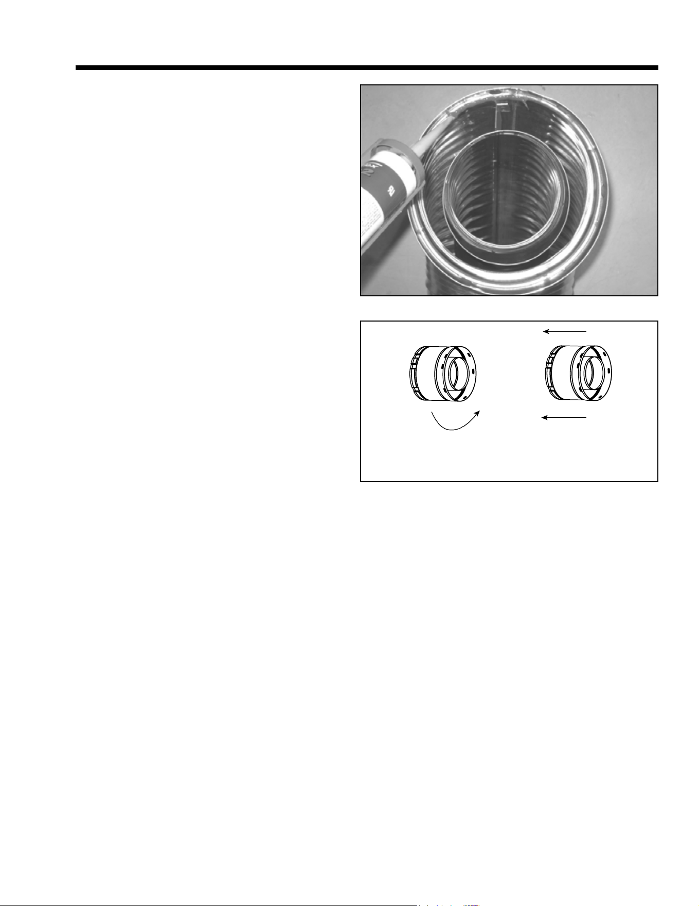
Figure 7.1 - High Temperature Silicone Sealant
A. Assemble Vent Sections
To attach the rst vent component to the starting collars of
the appliance:
• Lock the vent components into place by sliding the pipe
section onto the collar.
• Align the seam of the pipe and seam of collar to allow
engagement. Rotate the vent component to lock into place.
Use this procedure for all vent components. See Figure
7.2.
• Continue adding vent components, locking each
succeeding component into place.
• Ensure that each succeeding vent component is securely
tted and locked into the preceding component.
Required Commercial, Multi-family (Multi-level exceeding
two stories), or High-Rise Applications
For installation into a commercial, multi-family (multi-level
exceeding two stories) or high-rise applications: All outer
pipe joints must be sealed with high temperature silicone
(300ºF minimum continuous exposure rating), including
the slip section that connects directly to the horizontal
termination cap.
• Apply a bead of silicone sealant (300ºF minimum
continuous exposure rating) inside the female outer pipe
joint prior to joining sections. See Figure 7.1.
• Only outer pipes need to be sealed. All unit collar, pipe,
slip section, elbow and cap outer ues shall be sealed in
this manner, unless otherwise stated.
WARNING! Risk of Fire or Explosion! DO NOT break
silicone seals on slip sections. Use care when removing
termination cap from slip pipe. If slip section seals are
broken during removal of the termination cap, vent may
leak.
Figure 7.2 - Adding Venting Components
Note: Align seams to engage pipe,
then rotate counterclockwise to lock
Hearth & Home Technologies • CK-30 Cabinet Kit Installation Manual • 4126-900 Rev D • 2/2429
B. Assemble Slip Sections
• Slide the inner ue of the slip section into the inner ue of
the pipe section and the outer ue of the slip section over
the outer ue of the pipe section. See Figure 7.3.
• Slide together to the desired length.
Figure 7.4 - Screws into Slip Section
• Continue adding pipe as necessary following instructions
in “Assembling Pipe Sections.”
NOTICE: If slip section is too long, the inner and outer ues
of the slip section can be cut to the desired length.
• Apply a bead of silicone sealant (300ºF minimum
continuous exposure rating) inside the female outer pipe
joint prior to joining sections.
• Only outer pipes are sealed, sealing the inner ue is not
required.
• All unit collar, pipe, slip section, elbow and cap outer ues
shall be sealed.
Figure 7.3 - Slip Section Pilot Holes
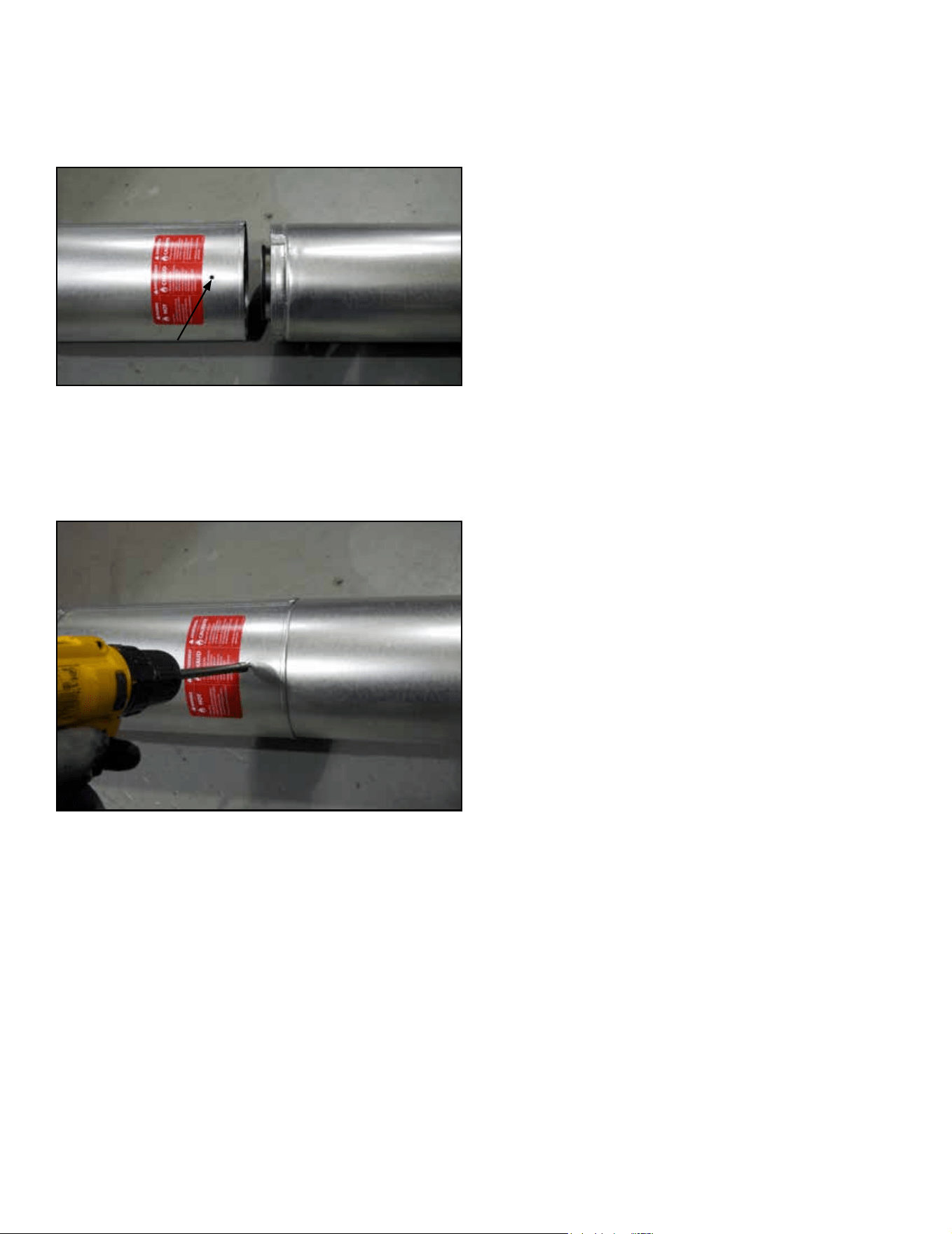
• Maintain a 1-1/2 in. (38 mm) overlap between the slip
section and the pipe section.
• Secure the pipe and slip section with three screws no
longer than 1/2 in. (13 mm), using the pilot holes in the slip
section. See Figure 7.4.
Pilot holePilot hole
Hearth & Home Technologies • CK-30 Cabinet Kit Installation Manual • 4126-900 Rev D • 2/2430
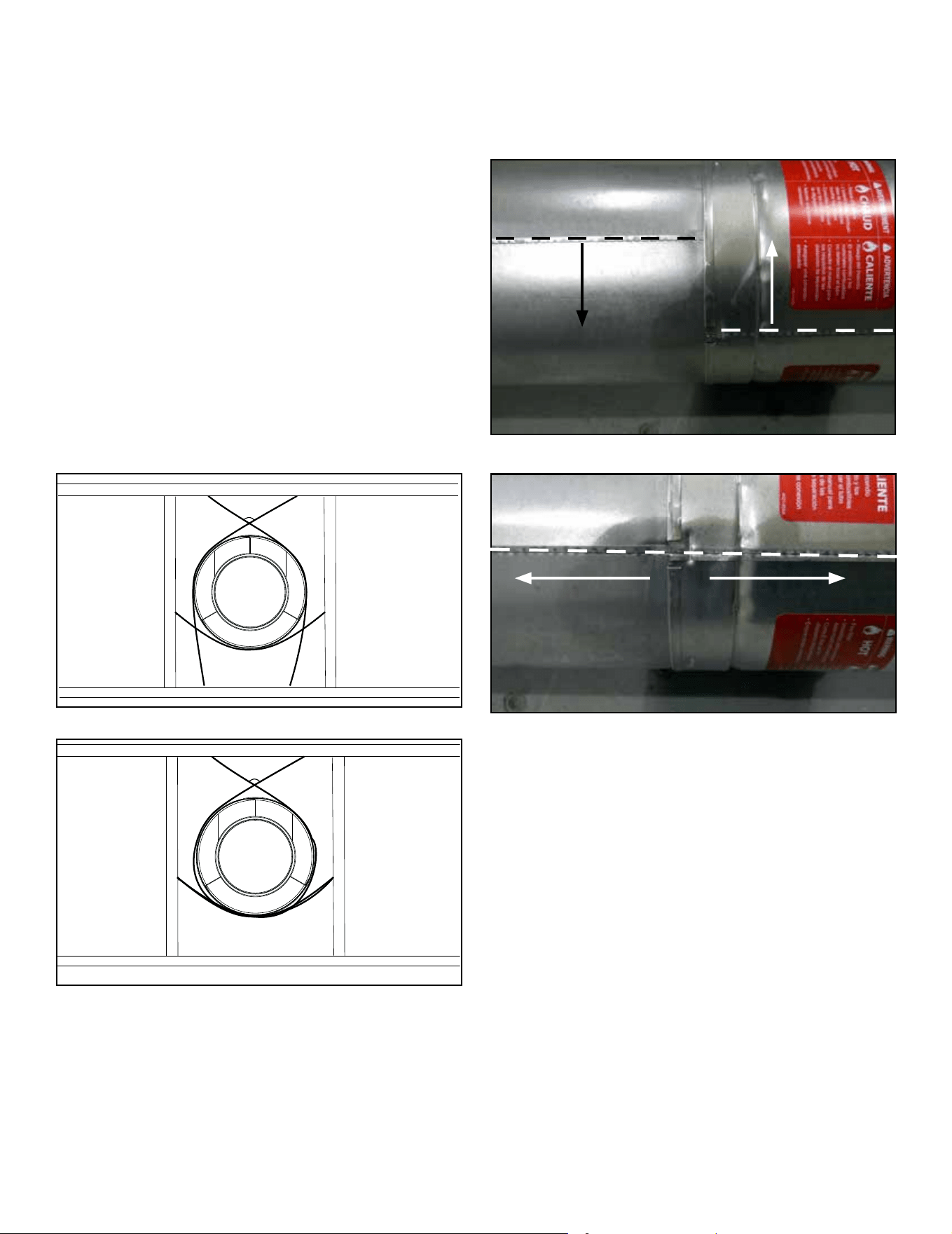
120º
Figure 7.5 - Securing Vertical Pipe Sections
120º
Figure 7.6 - Securing Horizontal Pipe Sections
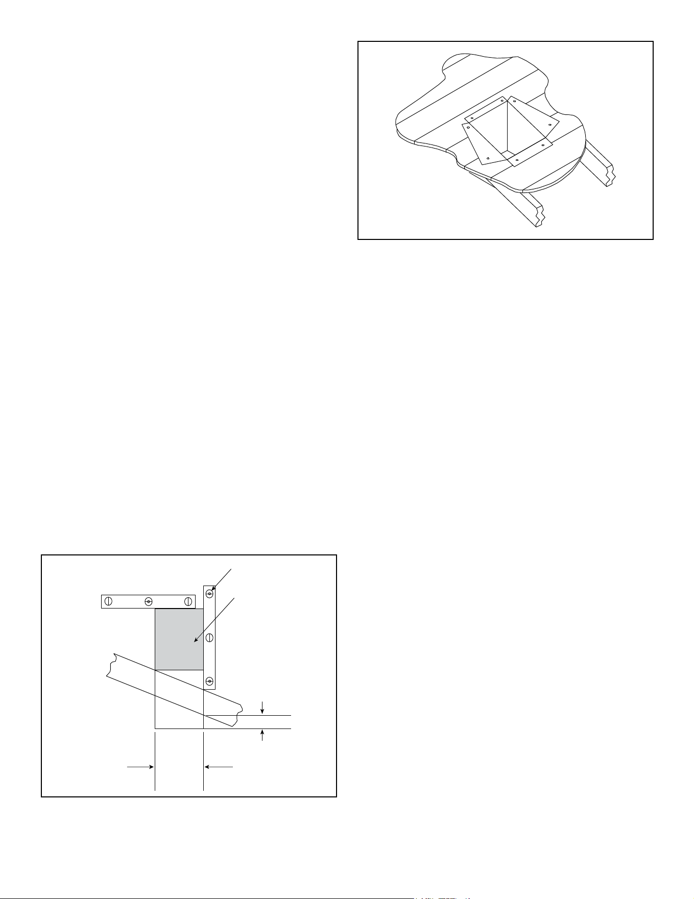
D. Disassemble Vent Sections
• Rotate either section (see Figure 7.7) so the seams on
both pipe sections are aligned as shown in Figure 7.8.
• Pull carefully to separate the pieces of pipe.
C. Secure the Vent Sections
• Vertical runs originating o the top of the appliance, with
no osets, must be supported every 8 ft. (2.44 m) after the
maximum allowed 25 ft. (7.62 m) of unsupported rise.
• Vertical runs originating o the rear of the appliance, or
after any elbow, must be supported every 8 ft. (2.44 m).
• Horizontal runs must be supported every 5 feet (1.52 m).
• Vent supports or plumbers strap (spaced 120º apart) may
be used to support vent sections. See Figures 7.5 and
7.6.
• Wall shield restops may be used to provide horizontal
support to vent sections.
• SLP ceiling restops have tabs that may be used to provide
vertical support.
WARNING! Risk of Fire, Explosion or Asphyxiation!
Improper support may allow vent to sag and separate. Use
vent run supports and connect vent sections per installation
instructions. DO NOT allow vent to sag below connection
point to appliance.
Figure 7.8 - Align and Disassemble Vent Sections
Figure 7.7 - Rotate Seams for Disassembly
Hearth & Home Technologies • CK-30 Cabinet Kit Installation Manual • 4126-900 Rev D • 2/2431
Install Decorative Ceiling Components
A decorative ceiling thimble can be installed on a at ceiling
through which the vent passes. The decorative ceiling
thimble is used to cover the restop.
• Seal the gap between the vent pipe and restop using high
temperature silicone (300ºF minimum continuous exposure
rating) to prevent cold air inltration.
• Install the decorative ceiling thimble by sliding it up to the
ceiling and attaching it using the provided screws.
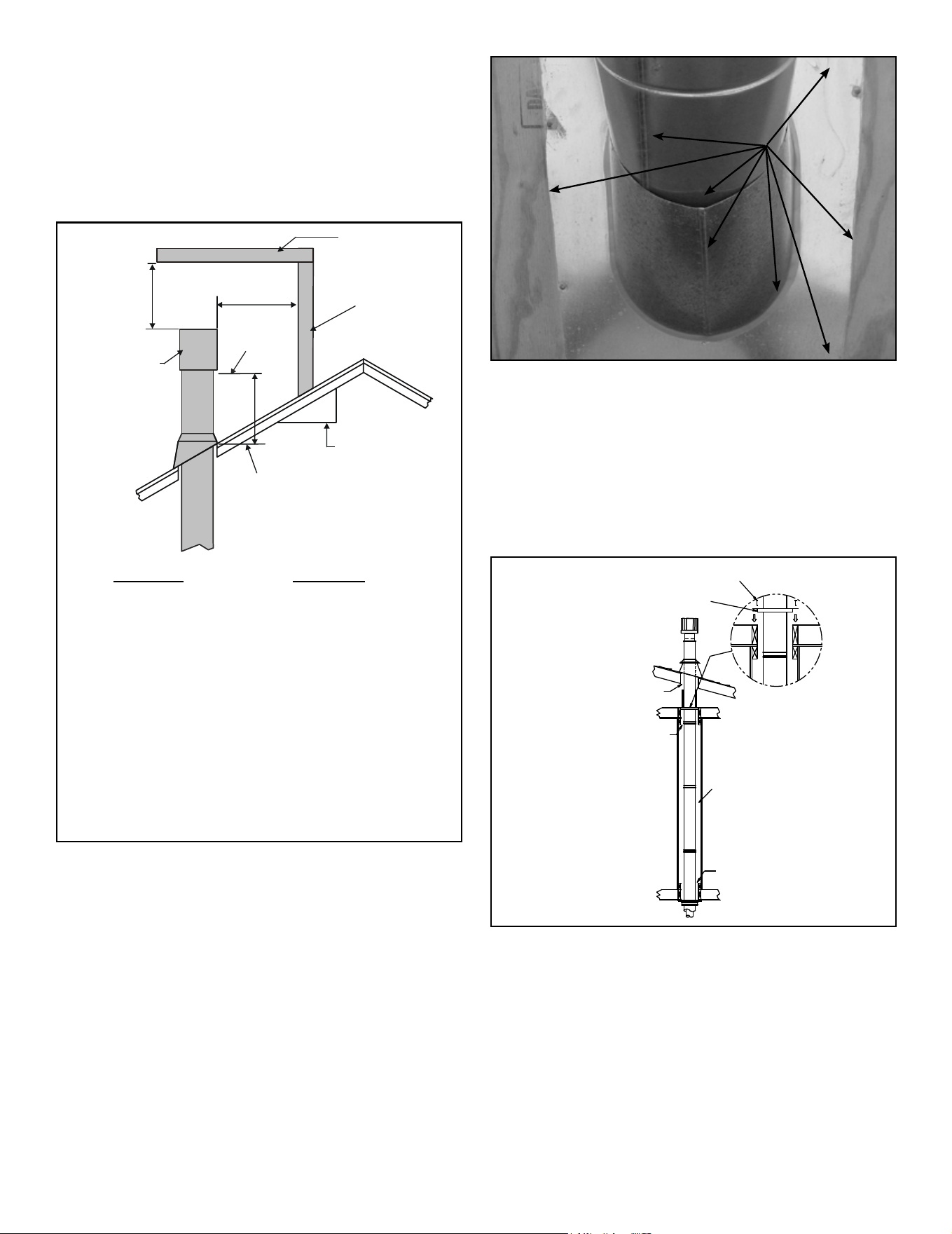
A decorative cathedral ceiling support box can be installed
on a cathedral ceiling through which the vent passes.
• Use a plumb-bob to mark the center line of the venting
system on the ceiling and drill a small hole through the
ceiling and roof at this point. Locate the hole and mark the
outline of the cathedral ceiling support box on the outside
roof.
• Remove shingles or other roof covering as necessary to
cut the rectangular hole for the support box. Cut the hole
1/8 in. (3 mm) larger than the support box outline.
• Lower the support box through the hole in the roof until its
bottom is at least 2 in. (51 mm) below the ceiling (Figure
7.9).
• Level the support box both vertically and horizontally and
temporarily tack it in place through the inside walls into the
roof sheathing.
• Use tin snips to cut the support box from the top corners
down to the roof line and fold the resulting aps to the roof.
See Figure 7.10.
• Nail the aps to the roof AFTER running a bead of non
hardening sealant between the aps and the roof.
WARNING! Risk of Fire! Clean out ALL materials from
inside the support box and complete the vertical vent run
and termination.
LEVEL
CATHEDRAL CEILING
SUPPORT BOX
2 in. (51 mm) MIN. BELOW
FINISHED CEILING
CUT HOLE 1/8 in. (3 mm)
GREATER IN SIZE THAN
PATTERN OF SUPPORT
BOX AS IT IS PROJECTED
ONTO ROOF LINE
Figure 7.9
Figure 7.10
Hearth & Home Technologies • CK-30 Cabinet Kit Installation Manual • 4126-900 Rev D • 2/2432
E. Vertical Termination Requirements
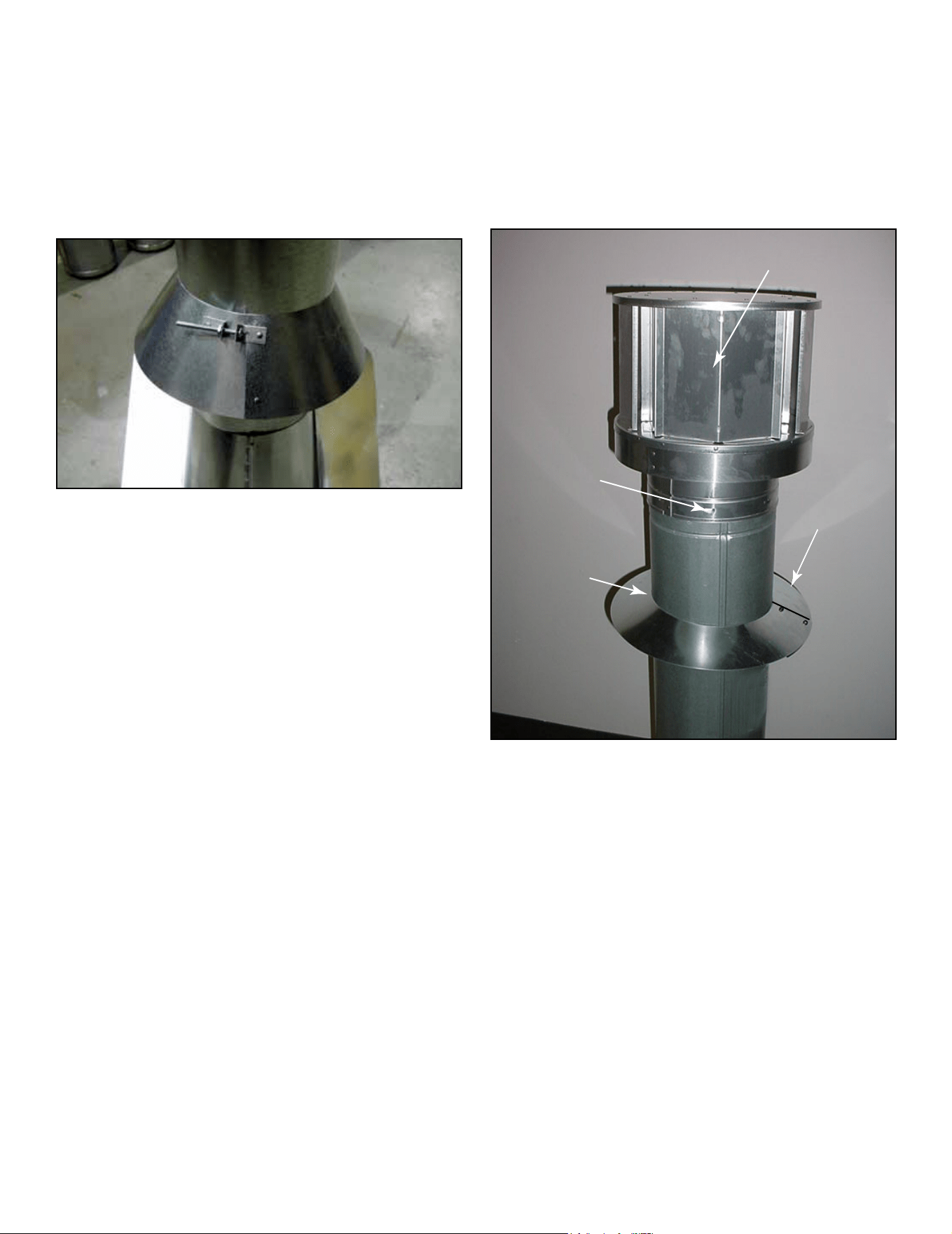
Install Metal Roof Flashing
• See minimum vent heights for various pitched roofs (Figure
7.11) to determine the length of pipe to extend through the
roof.
• Slide the roof ashing over the pipe sections extending
through the roof as shown in Figure 7.12.
Roof Pitch H (Min.) Ft.
Flat to 6/12........................................1.0*
Over 6/12 to 7/12 ............................1.25*
Over 7/12 to 8/12 ..............................1.5*
Over 8/12 to 9/12 ..............................2.0*
Over 9/12 to 10/12 ............................2.5*
Over 10/12 to 11/12 ......................... 3.25
Over 11/12 to 12/12 ........................... 4.0
Over 12/12 to 14/12 ........................... 5.0
Over 14/12 to 16/12 ........................... 6.0
Over 16/12 to 18/12 ........................... 7.0
Over 18/12 to 20/12 ........................... 7.5
Over 20/12 to 21/12 ........................... 8.0
* 3 foot minimum in snow regions
HORIZONTAL
OVERHANG
VERTICAL
WALL
GAS DIRECT VENT
TERMINATION CAP
12
X
ROOF PITCH
IS X/ 12
LOWEST
DISCHARGE
OPENING
2 FT.
MIN.
20 INCHES MIN.
H (MIN.) - MINIMUM HEIGHT FROM ROOF
TO LOWEST DISCHARGE OPENING
Figure 7.11 - Minimum Height From Roof To Lowest Discharge Opening
NOTICE: Failure to properly caulk the roof ashing and pipe
seams may permit entry of water.
• Caulk the gap between the roof ashing and the outside
diameter of the pipe.
• Caulk the perimeter of the ashing where it contacts the
roof surface. See Figure 7.12.
• Caulk the overlap seam of any exposed pipe sections that
are located above the roof line.
CAULKCAULK
Ceiling Firestop
Nails
Minimum 1 in.
(25mm) Clearance
Minimum 1 in.
(25mm) Clearance
Minimum 1 in.
(25mm) Clearance
Minimum 1 in.
(25mm) Clearance
Figure 7.13
Figure 7.12
• Any occupied areas above the rst oor, including closets
and storage spaces, which the vertical vent passes through
must be enclosed. See Figure 7.13 for required clearances
between vent and enclosure.
WARNING! Risk of Fire! Maintain air space clearance to
vent. DO NOT pack insulation or other combustibles around
vent system. Failure to keep insulation or other material
away from vent pipe may cause overheating and re.
Hearth & Home Technologies • CK-30 Cabinet Kit Installation Manual • 4126-900 Rev D • 2/2433
Assemble and Install Storm Collar
CAUTION! Risk of Cuts, Abrasions or Flying Debris.
Wear protective gloves and safety glasses during
installation. Sheet metal edges are sharp.
• Slide the storm collar onto the exposed pipe section
and align brackets.
• Insert a bolt (provided) through the brackets and install
nut. Do not completely tighten.
Figure 7.14 - Insert Bolt into Brackets
• Slide the assembled storm collar down the pipe section
until it rests on the roof ashing (see Figure 7.14).
• Tighten nut and make sure the collar is tight against the
pipe section.
• Caulk around the top of the storm collar. See Figure 7.15.
Termination Cap
(1 of 3)
Storm
Collar
Caulk
Screws
Figure 7.15
Install Vertical Termination Cap
• Attach the vertical termination cap by sliding the inner
collar of the cap into the inner ue of the pipe section while
placing the outer collar of the cap over the outer ue of the
pipe section.
• Secure the cap by driving three self-tapping screws
(supplied) through the pilot holes in the outer collar of the
cap into the outer ue of the pipe (see Figure 7.15).

Hearth & Home Technologies • CK-30 Cabinet Kit Installation Manual • 4126-900 Rev D • 2/2434
A. General Information
WARNING! Risk of Shock or Explosion! DO NOT wire
110-120 VAC to the valve or to the appliance wall switch.
Incorrect wiring will damage controls.
NOTICE: This appliance must be electrically wired and
grounded in accordance with local codes or, in the absence
of local codes, with National Electric Code ANSI/NFPA
70-latest edition or the Canadian Electric Code CSA C22.1.
• Plug the cord from the appliance junction box to
unswitched 110-120 VAC. This is required for proper
operation of the appliance.
• A 110-120 VAC circuit for this product must be protected
with ground-fault circuit-interrupter protection, in
compliance with the applicable electrical codes, when it is
installed in locations such as in bathrooms or near sinks.
• Low voltage and 110-120 VAC voltage cannot be shared
within the same wall box.
WARNING! Risk of Shock! Plug 3-pronged (grounding)
plug directly into a properly grounded 3-pronged receptacle.
DO NOT cut or remove grounding prong from plug.
Accessories Requirements
• This appliance may be used with a wall switch, wall
mounted thermostat and/or a remote control.
Wiring for optional Hearth & Home Technologies approved
accessories should be done now to avoid reconstruction.
Follow instructions that come with those accessories.
Electrical Service and Repair
WARNING! Risk of Shock! Label all wires prior to
disconnection when servicing controls. Wiring errors can
cause improper and dangerous operation. Verify proper
operation after servicing.
WARNING! Risk of Shock! Replace damaged wire with
type 105º C rated wire. Wire must have high temperature
insulation.
8 8
Electrical Information
B. Wiring Requirements
• (Refer to EXCURSION-II, RUBY30IN, RUBY30IL,
SUPREME-I30-IFT, SUPREME-I30-BIR OR SUPRM-
I30LP-IFT, TRILLIANT30IN Insert Installation
Manual)
(Refer to EXCURSION-II, RUBY30IN, RUBY30IL, SUPREME-I30-IFT, SUPREME-I30-BIR OR SUPRM-I30LP-IFT,
TRILLIANT30IN Insert Installation Manual)
►
►

Hearth & Home Technologies • CK-30 Cabinet Kit Installation Manual • 4126-900 Rev D • 2/2435
9 9
Gas Information
(Refer to EXCURSION-II, RUBY30IN, RUBY30IL, SUPREME-I30-IFT, SUPREME-I30-BIR OR SUPRM-I30LP-IFT,
TRILLIANT30IN Insert Installation Manual)
►
Hearth & Home Technologies • CK-30 Cabinet Kit Installation Manual • 4126-900 Rev D • 2/2436
10 10
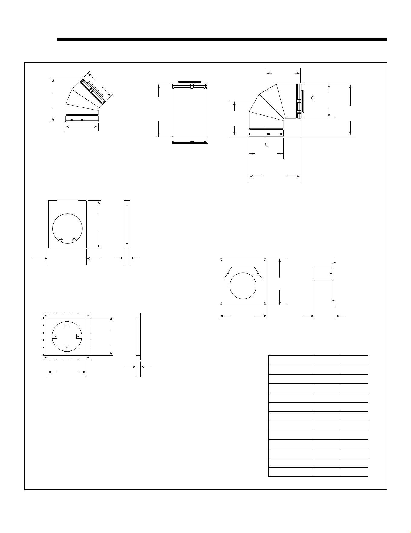
Reference Materials
A. Vent Components Diagrams
Figure 11.1 - SLP Series Vent Components
8-3/4 in.
222 mm
6-1/2 in.
165 mm
6-5/8 in.
168 mm
SLP45
45° Elbow
6 in.
152 mm
6-1/2 in.
165 mm
6-5/8 in.
168 mm
9-7/8 in.
251 mm
6-1/2 in.
165 mm
9-1/4 in.
235 mm
SLP90
90° Elbow
Effective
Height/
Length
SLP PIPE
SLP-HVS
Horizontal Pipe
Support
SLP-FS
Ceiling Firestop
SLP-WS
Wall Shield Firestop
10-7/8 in.
276 mm
8-7/8 in.
225 mm
1-1/2 in.
38 mm
8-11/16 in.
220 mm
8-11/16 in.
220 mm
1-1/2 in.
38 mm
12 in.
305 mm
12 in.
305 mm
5-1/2 in.
146 mm
Eective Height/Length
Pipe
inches mm
SLP4 4 102
SLP6 6 152
SLP12 12 305
SLP24 24 610
SLP36 36 914
SLP48 48 1219
SLP6A 2 - 6 51 - 152
SLP12A 2 - 12 51 - 305
SLP-FLEX-2 24 610
SLP-FLEX-3 36 914
SLP-FLEX-5 60 1524
SLP-FLEX-10 120 3048
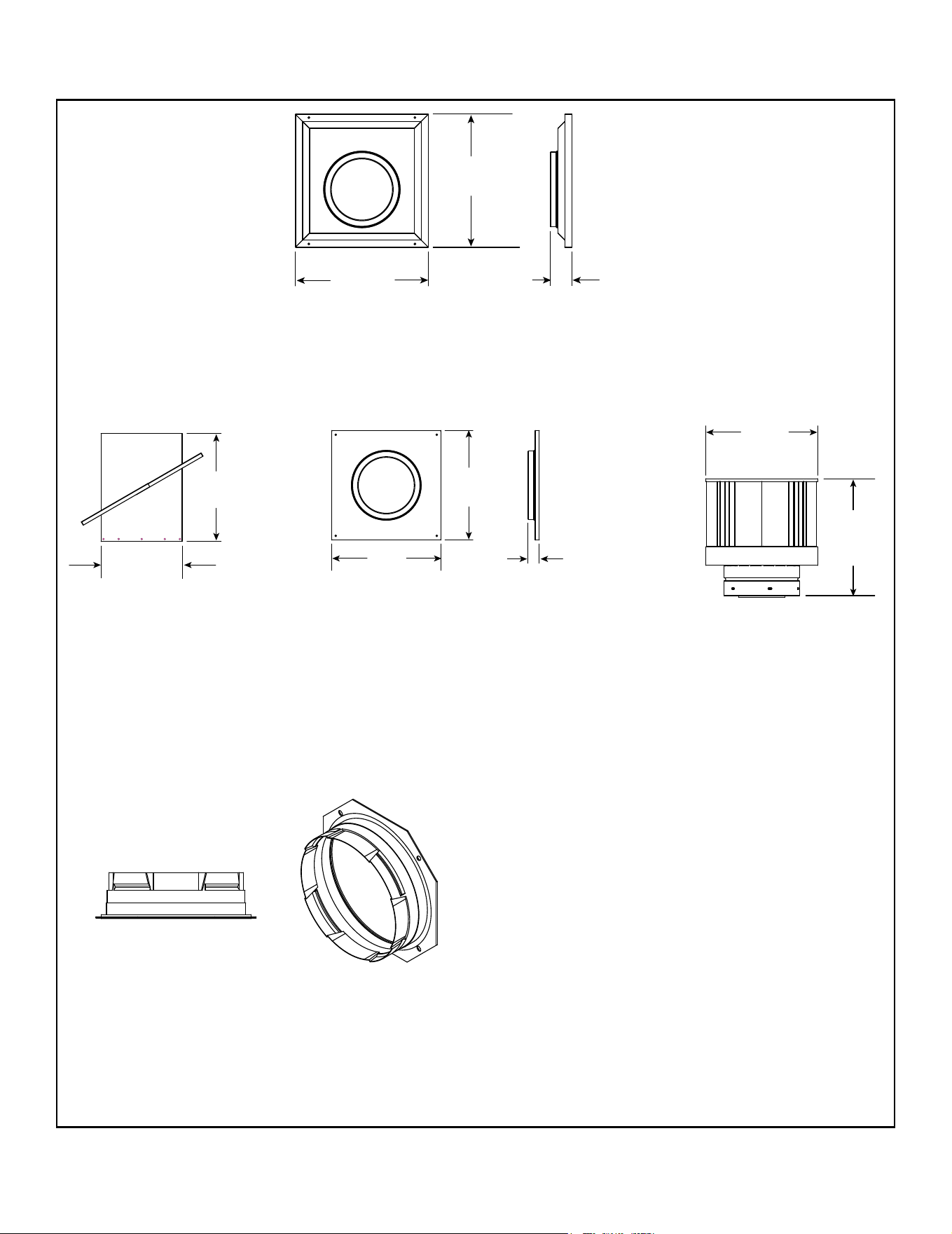
Hearth & Home Technologies • CK-30 Cabinet Kit Installation Manual • 4126-900 Rev D • 2/2437
A. Vent Components Diagrams (continued)
SLP-WT-BK
Wall Thimble-Black
14-7/16 in.
367 mm
14-7/16 in.
367 mm
2-5/16 in.
59 mm
Figure 11.2 - SLP Series Vent Components
10-9/16 in.
269 mm
14 in.
356 mm
SLP-CCS-BK
Cathedral Ceiling
Support Box-Black
13 in.
330 mm
13 in.
330 mm
1-5/16 in.
34 mm
SLP-DCF-BK
Ceiling Firestop
Black
12-1/2 in.
318 mm
12 in.
305 mm
SLP-TVHW
Vertical
Termination Cap
STOVEDV-BK
Simpson Duravent
Pipe Adapter Collar
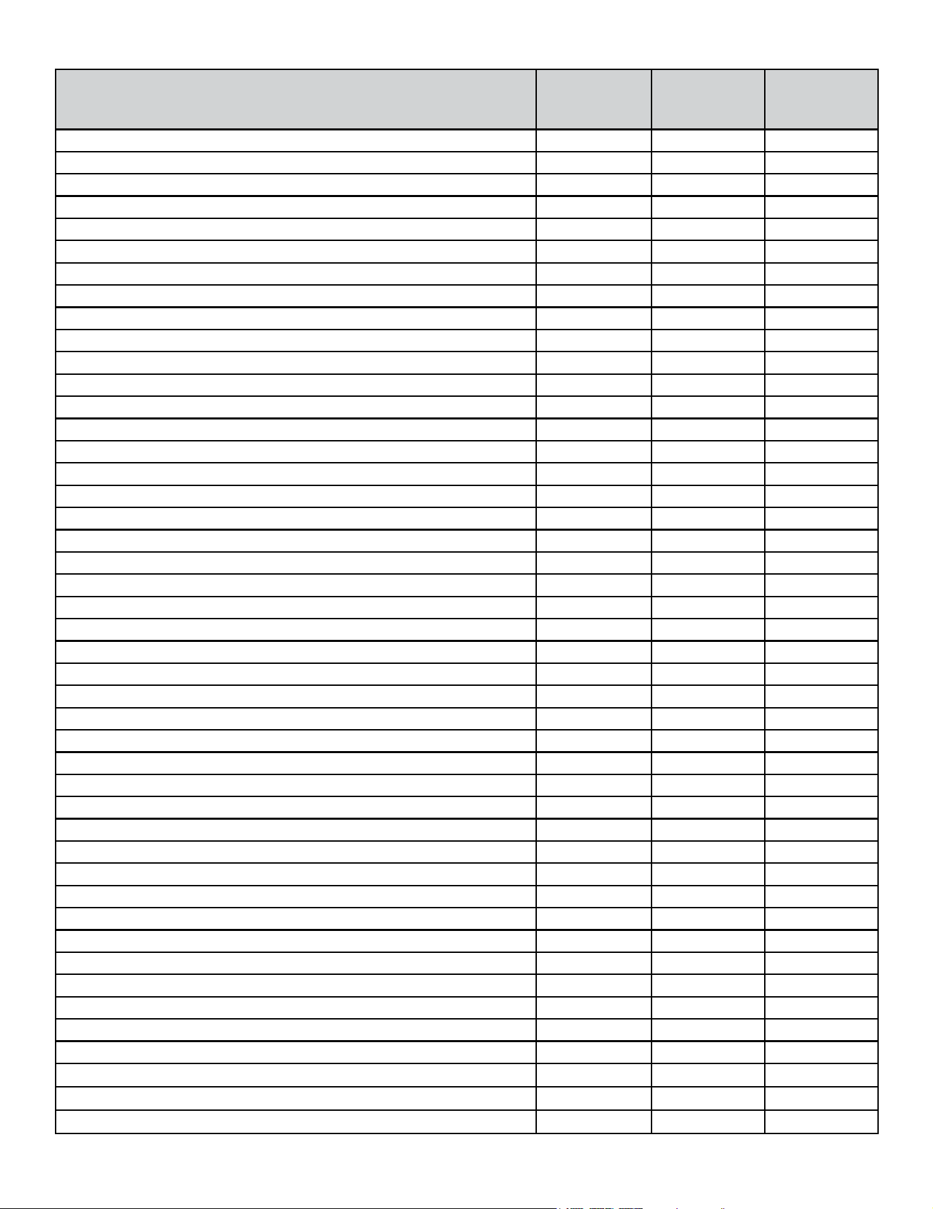
Hearth & Home Technologies • CK-30 Cabinet Kit Installation Manual • 4126-900 Rev D • 2/2438
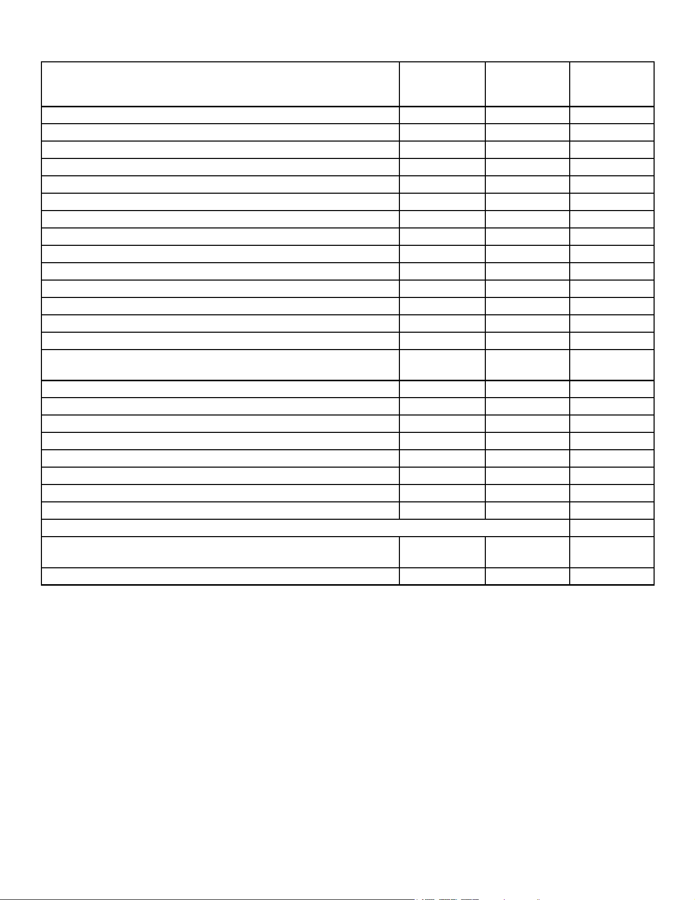
B. Vent Components List
Description
HHT SL-P
M= Multi Pack (6)
Simpson
Dura-Vent
DirectVent Pro
ICC
Chimney
4” Pipe Length, Galvanized SLP4M - -
4” Pipe Length, Black SLP4-BK - -
6” Pipe Length, Galvanized SLP6M 46-DVA-06 DL6
6” Pipe Length, Black SLP6-BK 46-DVA-06B DL6B
7” Pipe Length, Galvanized - - -
7” Pipe Length, Black - - -
9” Pipe Length, Galvanized - 46-DVA-09 DL9
9” Pipe Length, Black - 46-DVA-09B DL9B
12” Pipe Length, Galvanized SLP12M 46-DVA-12 DL1
12” Pipe Length, Black SLP12-BK 46-DVA-12B DL1B
18” Pipe Length, Galvanized - 46-DVA-18 -
18” Pipe Length, Black - 46-DVA-18B -
24” Pipe Length, Galvanized SLP24M 46-DVA-24 DL2
24” Pipe Length, Black SLP24-BK 46-DVA-24B DL2B
36” Pipe Length, Galvanized SLP36M 46-DVA-36 DL3
36” Pipe Length, Black SLP36-BK 46-DVA-36B DL3B
48” Pipe Length, Galvanized SLP48M 46-DVA-48 DL4
48” Pipe Length, Black SLP48-BK 46-DVA-48B DL4B
Adjustable Length, 3”-6”, Black SLP6A-B - -
Adjustable Length, 3”-6”, Galvanized SLP6AM - -
Adjustable Length, 3”-7”, Galvanized - 46DVA-08A -
Adjustable Length, 3”-7”, Black - 46DVA-08AB -
Adjustable Length, 3”-12”, Black SLP12A-BK - DLS1
Adjustable Length, 3”-12”, Galvanized SLP12AM - DLS1B
Adjustable Length, 3”-14.5”, Galvanized - 46DVA-16A -
Adjustable Length, 3”-14.5”, Black - 46DVA-16AB -
Adjustable Length, 7”, Galvanized - - -
Adjustable Length, 7”, Black - - -
Adjustable Length, 11”-14”, Galvanized - - -
Adjustable Length, 11”-14”, Black - - -
Adjustable Length, 12”, Galvanized - 4DT-AJ12 -
Adjustable Length, 12”, Black - 4DT-AJ12B -
Adjustable Length, 16”, Galvanized - 46DVA-16A DLS2
Adjustable Length, 16”, Black - 46DVA-16AB DLS2B
Adjustable Length, 24”, Galvanized - - -
Adjustable Length, 24”, Black - - -
2’ Flexible Pipe Length SLP-FLEX-2 - -
3’ Flexible Pipe Length SLP-FLEX-3 - -
5’ Flexible Pipe Length SLP-FLEX-5 - -
10’ Flexible Pipe Length SLP-FLEX-10 - -
3” x 35’ Flex Extension - 3DFA-35 -
4” x 35’ Flex Extension - 4DFA-35 -
45° Elbow, Galvanized SLP45M -
4DE45
45° Elbow, Black SLP45-BK See Swivel
4DE45B
45° Elbow, Swivel, Galvanized - 46DVA-E45
-
Hearth & Home Technologies • CK-30 Cabinet Kit Installation Manual • 4126-900 Rev D • 2/2439
B. Vent Components List (Cont)
NOTES:
1
BEFORE CUTTING ANY HOLES CHECK PIPE MANUFACTURERS CURRENT INSTRUCTIONS.
2
EACH PIPE MANUFACTURER HAS THEIR OWN LIST OF PARTS FOR KITS.
3
SL IS NOT INTERCHANGEABLE WITH SLP.
Description
HHT SL-P
M= Multi Pack (6)
Simpson
Dura-Vent
DirectVent Pro
ICC
Chimney
45° Elbow, Swivel, Black - 46DVA-E45B
-
90° Elbow, Galvanized SLP90M See Swivel
4DE90
90° Elbow, Swivel, Galvanized - 46DVA-E90
-
90° Elbow, Swivel, Black - 46DVA-E90B
4DE90B
Adjustable Flashing, 0/12-6/12 SLP-RF6M 46DVA-F6
4FA
Adjustable Flashing, 7/12-12/12 SLP-RF12M 46DVA-F12
4FB
Attic Insulation Shield - Cold Climates 36” - -
-
Attic Insulation Shield 12” SLP-AS2M -
-
Attic Insulation Shield, Adjustable 11”-20” - 46-DVA-IS
4AS
Cathedral Support Box SLP-CCS-BK 46DVA-CS
4SS
Ceiling Support - 46DVA-DC
4CS
Decorative Ceiling Firestop - Black SLP-DCF-BK -
4TR
Decorative Radius Cover DRC-RADIUS -
-
Firestop Spacer/Ceiling Firestop SLP-FSM 46DVA-FS
-
Masonry Chimney Conversion Kit (Includes Cap Adapter, 18 x 18 Flashing, Ceiling
Support/Wall Thimble and Retro Connectors)
- 46DVA-KMC
-
Offset Support - 46DVA-ES
OS
Offset Wall Thimble, Black SLP-WT-BK -
-
Silicone Roof Flashing, 4” to 8” pipes (6) RF4-8M -
-
Storm Collar SLP-SCM 46DVA-SC
SC
Trim Plate, Black - -
4TP
Wall Support Band SLP-HVSM 46-DVA-WS
WS
Wall Thimble Support Box/Ceiling Support - -
4WT
Wall Thimble, Black SLP-WSM 46DVA-WT
-
TERMINATION CAPS & KITS
Stove Adaptor Kit (Vertical Cap Kit) (Includes 30’- 4” Flex, Adapters, Wall Thimble,
Masonry ZC Flashing and 991DA Vertical Cap)
LINK-STOVE -
-
Vertical Termination Cap SLP-TVHW 46DVA-VCH
VT

Hearth & Home Technologies • CK-30 Cabinet Kit Installation Manual • 4126-900 Rev D • 2/2440
Hearth & Home Technologies
7571 215th Street West, Lakeville, MN 55044
www.hearthnhome.com
Please contact your Hearth & Home Technologies dealer with any questions or concerns.
For the location of your nearest dealer,
please visit www.hearthnhome.com.
Printed in U.S.A. - Copyright 2014