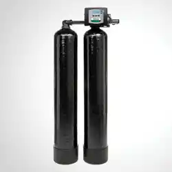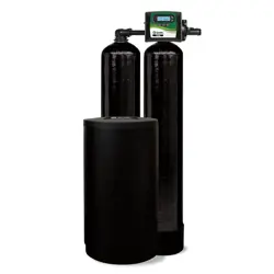
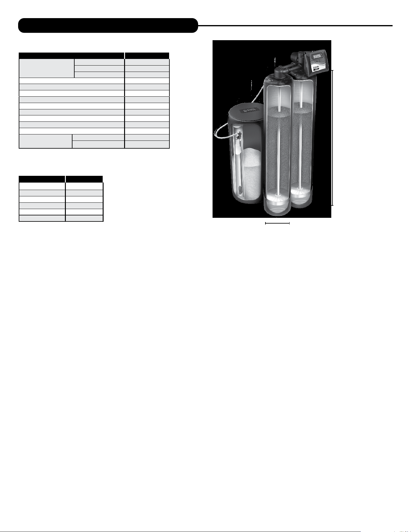
Twin Water Softeners
For Models:
• APR-TW

Pre-Installation Instructions for Dealers ........................................ 3
Bypass Valve .............................................................. 4
Installation ................................................................ 5
Programming Procedures .................................................... 7
Start-Up Instructions ....................................................... 8
Operating Displays and Maintenance .......................................... 9
Troubleshooting Guide ..................................................... 11
Replacement Parts ........................................................ 18
Installation Fitting Assemblies .............................................. 26
Specifications ............................................................. 29
Warranty ................................................................. 30
Quick Reference Guide ..................................................... 31
TABLE OF CONTENTS
Your twin system softener is a precision built, high quality product. These units will deliver conditioned water for many years
to come when installed and operated properly. Please study this manual carefully and understand the cautions and notes
before installing. This manual should be kept for future reference. If you have any questions regarding your twin water system,
contact your local dealer.
YOUR WATER TEST
Hardness ______________________ gpg
Iron __________________________ ppm
pH ___________________________ number
*Nitrates ______________________ ppm
Manganese ____________________ ppm
Sulphur _______________________ yes/no
Total Dissolved Solids ____________
*Over 10 ppm may be harmful for human consumption.
Water conditioners do not remove nitrates or coliform bacteria,
this requires specialized equipment.
PRODUCT INFORMATION
MODEL NUMBER
SERIAL NUMBER
DEALER INFORMATION:

3
PRE-INSTALLATION INSTRUCTIONS
THE DEALER SHOULD...
•Read this page and guide the installer
regarding hardness, day override, and time of
regeneration before installation.
THE INSTALLER SHOULD...
•Program installer settings including hardness,
day override, and time of regeneration.
•Read Operating Displays and Maintenance
section.
•Set the time of day
•Read Power Loss and Error Display section.
•Ensure that system and installation are in
compliance with all state and local laws and
regulations.
THE HOMEOWNER SHOULD...
•Read Programming Procedures section.
•Read Operating Displays and Maintenance
section.
The manufacturer has preset the water treatment unit’s sequence of cycles, cycle times, salt dose, exchange capacity and salt dose refill time.
GENERAL OPERATING DISPLAYS & NAVIGATION
During normal operation, the default user displays are “time of day” and “gallons per minute”. Flow rate, capacity remaining, and days to a
regeneration are optional displays. For more explanation, consult the “operating displays and maintenance section”. Pressing the NEXT button on a
general operating screen will cycle through the available operating displays.
In any screen other than a general operating display, the NEXT button will proceed to the next step, the REGEN button will return to a previous step,
and the CLOCK button will return to the general operating displays. Any changes made prior to the exit will be incorporated. If no buttons are pressed
within five minutes, the display will return to the general operating displays.
4
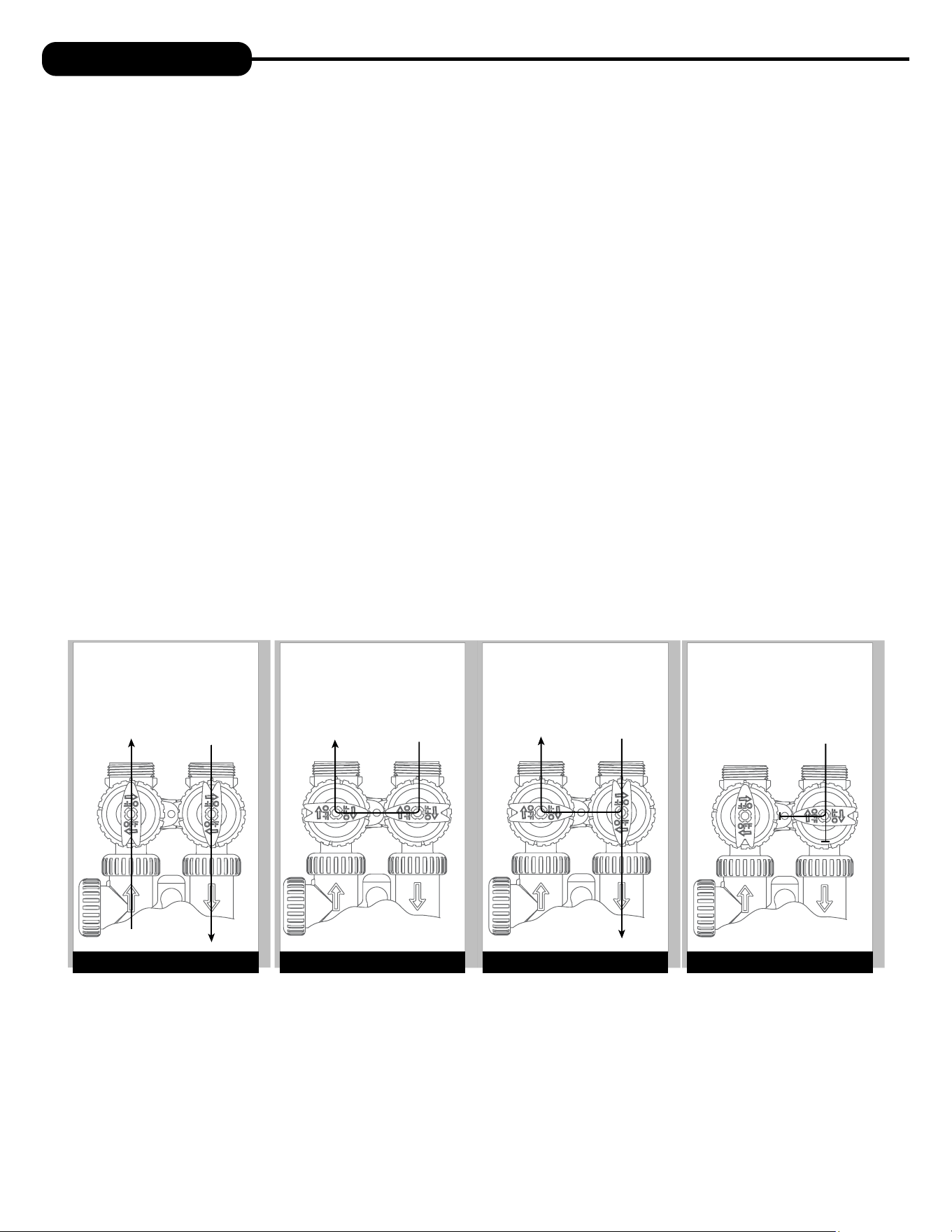
“TREATED”
WATER EXITS
SUPPLY
WATER ENTERS
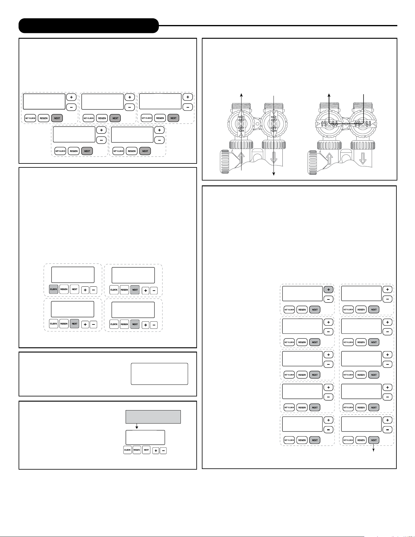
NORMAL OPERATION
POSITION
BYPASS POSITION DIAGNOSTIC POSITION SHUT OFF POSITION
FIGURE 1
SUPPLY
WATER EXITS
SUPPLY
WATER ENTERS
FIGURE 3
SUPPLY
WATER EXITS
SUPPLY
WATER ENTERS
FIGURE 2
NO
WATER EXITS
SUPPLY WATER IS
SHUT OFF
TO THE HOUSE
AND THE VA LV E
FIGURE 4
BYPASS VALVE
The bypass valve is typically used to isolate the control valve from the plumbing system’s water pressure in order to perform control
valve repairs or maintenance. The 1” full flow bypass valve incorporates four positions, including a diagnostic position that allows a
service technician to have pressure to test a system while providing untreated bypass water to the building. Be sure to install bypass
valve onto main control valve before beginning plumbing or make provisions in the plumbing system for a bypass. The bypass body and
rotors are glass-filled Noryl® and the nuts and caps are glass-filled polypropylene. All seals are self-lubricating EPDM to help prevent
valve seizing after long periods of non-use. Internal “O” Rings can easily be replaced if service is required.
The bypass consists of two interchangeable plug valves that are operated independently by red arrow shaped handles. The handles
identify the direction of flow. The plug valves enable the bypass valve to operate in four positions.
1. NORMAL OPERATION POSITION: The inlet and outlet handles point in the direction of flow indicated by the engraved
arrows on the control valve. Water flows through the control valve for normal operation of a water softener or filter. During the
regeneration cycle this position provides regeneration water to the unit, while also providing untreated water to the distribution
system (Fig. 1).
2. BYPASS POSITION: The inlet and outlet handles point to the center of the bypass. The system is isolated from the water
pressure in the plumbing system. Untreated water is supplied to the building (Fig. 2).
3. DIAGNOSTIC POSITION: The inlet handle points toward the control valve and the outlet handle points to the center of bypass
valve. Untreated supply water is allowed to flow to the system and to the building, while not allowing water to exit from the system
to the building (Fig. 3). This allows the service technician to test the unit and perform other functions without disrupting the water
going to the building.
NOTE: The system must be rinsed before returning the bypass valve to the normal position.
4. SHUT OFF POSITION: The inlet handle points to the center of the bypass valve and the outlet handle points away from the
control valve. The water is shut off to the building. The water treatment system will depressurize upon opening a tap in the building.
A negative pressure in the building combined with the unit being in regeneration could cause a siphoning to the building. If water
is available on the outlet side of the unit, it is an indication of water bypassing the system (Fig. 4) (i.e. a plumbing cross-connection
somewhere in the building).
4 5
COLD
HOT
SHUTOFF
VALV E
GROUND
STRAP
10 FEET
WATER SUPPLY
TO
DRAIN
WATER
HEATER
PRESSURE
TANK
OUTSIDE TAP
O
V
E
R
H
E
A
D
V
I
E
W
O
F
B
Y
P
A
S
S
V
A
L
V
E
OUT
IN
COLD
HOT
SHUTOFF
VALV E
GROUND
STRAP
10 FEET
WATER SUPPLY
TO
DRAIN
WATER
HEATER
WATER
METER
OUTSIDE TAP
O
V
E
R
H
E
A
D
V
I
E
W
O
F
B
Y
P
A
S
S
V
A
L
V
E
OUT
IN
INSTALLATION
GENERAL INSTALLATION & SERVICE WARNINGS
The control valve, fittings and/or bypass are designed to accommodate minor plumbing misalignments. There is a small amount of “give” to properly
connect the piping, but the water treatment unit is not designed to support the weight of the plumbing.
Do not use Vaseline, oils, other hydrocarbon lubricants, or spray silicone anywhere. A silicone lubricant may be used on black “O” Rings, but is not
necessary. Avoid any type of lubricants, including silicone, on red or clear lip seals.
Do not use pipe dope or other sealants on threads. Teflon® tape must be used on the threads of the 1” NPT inlet and outlet and on the threads for
the drain line connection. Teflon® tape is not used on the nut connections or caps because “O” Ring seals are used. The nuts and caps are designed
to be unscrewed or tightened by hand or with the special plastic Service Wrench, # 100249864 (CV3193-02). If necessary, pliers can be used to
unscrew the nut or cap. Do not use a pipe wrench to tighten nuts or caps. Do not place screwdriver in slots on caps and/or tap with a hammer.
SITE REQUIREMENTS
• Water pressure – 30-100 psi • Current draw is 0.5 amperes
• Water temperature – 33-100°F (0.5-37.7°C) • The plug-in transformer is for dry locations only
• Electrical – 115/120V, 60Hz uninterrupted outlet
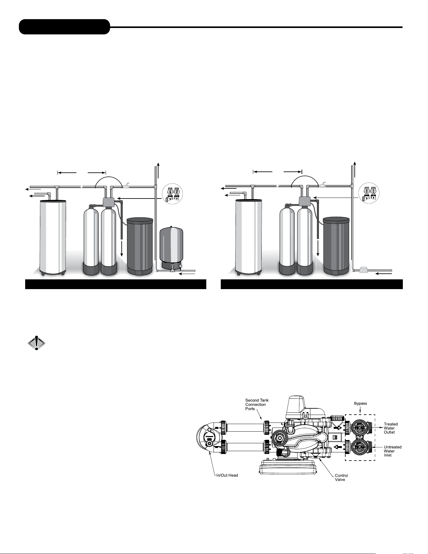
WELL WATER INSTALLATION MUNICIPAL INSTALLATION
1. The distance between the drain and the water conditioner should be as short as possible (see #9).
2. Since salt must be added periodically to the brine tank, it should be in an easily accessible location.
3. The media tanks should be installed on a firm, level surface (above or below grade).
4. It is NOT recommended to install any water treatment unit with less than 10 feet of piping between its outlet and the inlet of a water heater.
CAUTION: To protect the unit in the event of a hot water heater backup, the manufacturer recommends the use of an expansion tank
on the outlet side of the unit (see diagram).
5. Do not locate unit where it or its connections (including the drain and overflow lines) will ever be subjected to temperatures under 33°F.
6. Do not subject the tank to any vacuum as this may cause an “implosion” and could result in leaking. If there is a possibility a vacuum could
occur, please make provision for a vacuum breaker in the installation.
7. INLET/OUTLET PLUMBING: Be sure to install Bypass
Valve onto main control valve before beginning plumbing.
(See installation picture to right. Be sure bypass is
connected to treated water inlet and outlet.) If it is
desired to bypass outside hydrants, a cold water kitchen
sink, or other locations, provisions should be made at this
time. Install an inlet shutoff valve and plumb to the unit’s
bypass valve inlet located at the right front as you face the
unit. There are a variety of installation fittings available.
They are listed under the Installation Fitting Assemblies
section of the manual. When assembling the installation
fitting package (inlet and outlet), connect the fitting to the
plumbing system first and then attach the nut, split ring
and “O” Ring. Heat from soldering or solvent cements may
damage the nut, split ring or “O” Ring. Solder joints should be cool and solvent cements should be set before installing the nut, split ring
and “O” Ring. Avoid getting solder flux, primer, and solvent cement on any part of the “O” Rings, split rings, bypass valve or control valve. If the
building’s electrical system is grounded to the plumbing, install a copper grounding strap from the inlet to the outlet pipe. Plumbing must be done
in accordance with all applicable local codes.
6
INSTALLATION
8. INSTALLING GROUND: To maintain an electrical ground in metal plumbing of a home’s
cold water piping (such as a copper plumbing system), install a ground clamp or jumper wiring.
NOTE: If replacing an existing unit, also replace the ground clamps/wire. If removing
a unit, replace the piping with the same type of piping as the original to assure
plumbing integrity and grounding.
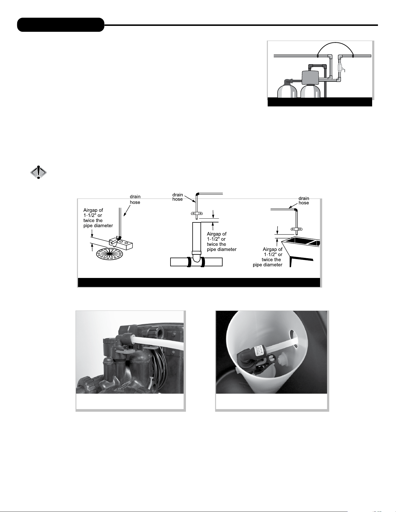
9. DRAIN LINE: First, be sure that the drain can handle the backwash rate of the system. Solder
joints near the drain must be done prior to connecting the drain line flow control fitting. Leave
at least 6” between the drain line flow control fitting and solder joints. Failure to do this could
cause interior damage to the flow control. Install a 1/2” I.D. tube to the Drain Line Assembly in
accordance with plumbing regulations or discard the tubing nut and use the 3/4” NPT fitting for
rigid pipe (recommended). If the backwash rate is greater than 7 gpm, use a 3/4” drain line. Where the drain line is elevated but empties into a
drain below the level of the control valve, form a 7” loop at the discharge end of the line so that the bottom of the loop is level with the drain
connection on the control valve. This will provide an adequate anti-siphon trap. Piping the drain line overhead <10 ft is normally not a problem.
Be sure adequate pressure is available (40-60 psi is recommended). Where the drain empties into an overhead sewer line, a sink-type trap must
be used with appropriate air gap (see drawing). Run drain tube to its discharge point in accordance with plumbing codes. Pay special attention
to codes for air gaps and anti-siphon devices.
CAUTION: Never insert a drain line into a drain, sewer line, or trap. Always allow an air gap of 1-1/2” or twice the pipe
diameter, whichever is greater, between the drain line and the wastewater to prevent the possibility of sewage
being back-siphoned into the softener.
GROUND STRAP
SHUTOFF
VALVE
GROUND
STRAP
TYPICAL DRAIN LINE INSTALLATIONS
1. Floor Drain 2. Standpipe 3. Laundry Tub
10. SAFETY BRINE TANK CONNECTION: Install the 3/8” O.D. polyethylene tube from the Refill Elbow to the Brine Safety Float valve in the
brine tank.
11. OVERFLOW LINE CONNECTION: An overflow drain line is recommended where a brine overflow could damage furnishings or the building
structure. Your unit is equipped with a brine tank safety float which greatly reduces the chance of an accidental brine overflow. In the event of
a malfunction, however, an overflow line connection will direct the “overflow” to the drain instead of spilling on the floor where it could cause
considerable damage. This fitting is an elbow on the side of the brine tank. Attach a length of 1/2” I.D. tubing to fitting and run to drain. Do not
elevate overflow line higher than 3” below bottom of overflow fitting. Do not connect this tube into the drain line of the control valve. Overflow
line must be a direct, separate line from overflow fitting to drain, sewer, or tub. The overflow line is a gravity drain and cannot run higher than
the initial drain point. Allow an air gap as per the drain line instructions.
Connection at Refill Elbow on the control valve
Connection at Brine Safety Float in brine tank
6 7
PROGRAMMING PROCEDURES
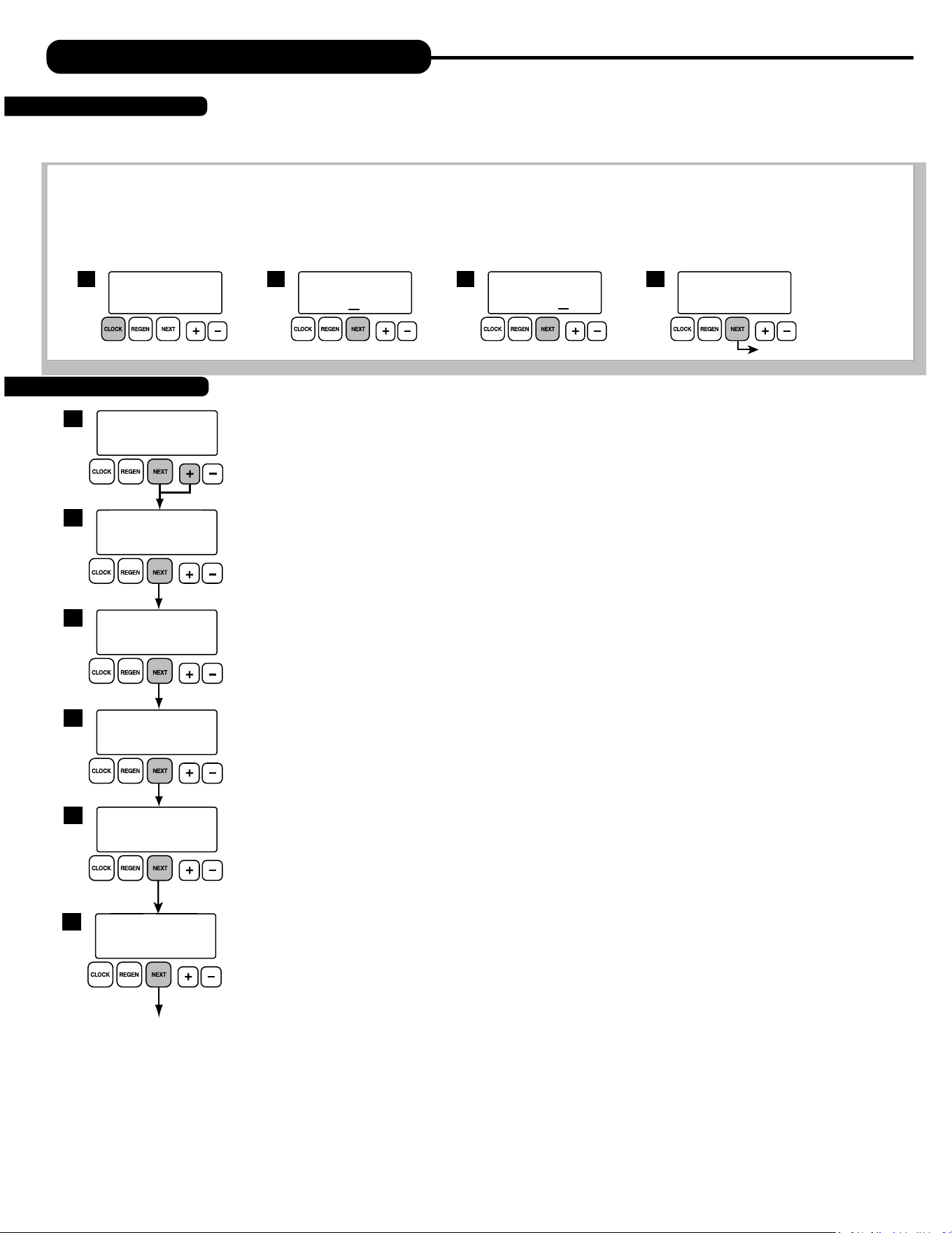
Typically, time of day should only need to be set after extended power outages or when daylight saving time begins or ends or after the battery has
been replaced. If an extended power outage occurs, the time of day will flash on and off indicating that the time should be reset. To set the clock:
STEP 1 – Press the CLOCK button.
STEP 2 – Set the hour of the day using
+ or – buttons. AM/PM toggles after 12. Press NEXT to go to step 3.
STEP 3 – Set the minutes using
+ or – buttons. Press NEXT to go to step 4 or REGEN to return to previous step.
STEP 4 – Set the day of the week using
+ or – buttons. Press NEXT to exit clock setting or REGEN to return to previous step.
1
TIME HOUR
AM
SET
2:00
TIME MINUTES
AM
SET
2:00
2 3
CURRENT DAY
SET
MON
4
return to general display
TIME OF DAY MON
PM
GPM
2:408
1. Set Time of Day
2. Programming
1
DAYS BETWEEN REGEN
SET
OFF
3
WATER HARDNESS
SET
20
2
REGEN IMMEDIATE
GAL
GR
ON ZERO
4
Return to general display.
LIGHT NORMALLY
SET
ON
6
ALARM BUZZER
SET
ON
5
The manufacturer has preset the unit so that the gallons between regenerations will be automatically calculated
after the hardness is entered. Press NEXT to cycle to the next step or REGEN to return to the previous step.
STEP 1 – Press and hold the NEXT and
+ buttons simultaneously for 3 seconds.
STEP 2 – HARDNESS: Use the
+ or – buttons to adjust the hardness value in grains per gallons. Adjustable
from 1 to 150 gpg in 1 grain increments (default setting is 20).
The hardness value is based on the actual compensated hardness of the water and must be set by
an authorized dealer following an on-site water analysis. Adjusting the number will only impact the
frequency of regeneration and will not alter or affect the hardness of the water treated by the unit.
Note: If a resin media is used, increase the grains per gallon if soluble iron is present
(1 ppm = 4 gpg). This screen will not display if “FILTER” mode is selected.
STEP 3 – DAYS BETWEEN REGENERATION (DAY OVERRIDE): Use the
+ or – buttons to adjust the day override.
Adjustable from 1-28 days or OFF. The manufacturer has factory set OFF as the default for Twin units.
The Day Override value represents the maximum number of days between regenerations. If any number
is set (1-28 days), a regeneration will be scheduled for that day if the gallon capacity has not been met. If
OFF is set, the unit will only initiate a regeneration once the gallon capacity has been met.
STEP 4 – IMMEDIATE REGENERATION: The manufacturer has set the regeneration to occur when zero gallons
remain. When this occurs, the standby tank will switch into service and provide treated water while the
tank requiring regeneration will start this process.
STEP 5 – ALARM BUZZER:
Use the + or – buttons to turn the alarm ON or OFF. Unit is set to ON by default. Alarm
will sound immediately if there is no salt detected in the brine tank or if an error has occurred.
STEP 6 – BACKLIGHT DISPLAY CONTROL: Use the + or – buttons to turn the backlight setting ON or OFF. If unit is
set to OFF, the backlight will turn off after 5 minutes of inactivity.
Press NEXT to return to General Display.
Note: To alternate between tanks without activating a regeneration, press and hold CLOCK and
+ buttons
simultaneously for three seconds.

8
FLUSHING OF SYSTEM:
To flush the system of any debris and air after installation is complete, please perform the following steps:
1. Rotate bypass handles to the bypass mode (Fig. 2 on page 4) .
2. Turn on inlet water and check for leaks in the newly installed plumbing.
3. Fully open a cold water faucet, preferable at a laundry sink or bathtub without an aerator.
4. Wait two to three minutes or until water runs clear, then turn water off and follow start-up instructions.
Below is the name of each cycle as it appears on the screen with a description of the cycle position. The timing of each cycle will vary
depending on the unit size as set from the factory.
Name of Cycle Description
BACKWASH BACKWASH
REGENERANT DRAW DOWN BRINE DRAW AND SLOW RINSE
RINSE RAPID RINSE
FILL BRINE TANK FILL
1. With the softener in the bypass mode (Fig. 2 on page 4) and the control valve in normal operation where the
display shows either the time of day or the gallons remaining, manually add 8” of water to the regenerant tank.
NOTE: If too much water is put into the brine tank during softener start up, it could result in a “salty water”
complaint after the first regeneration. During the first regeneration, the unit will draw out the initial volume of brine/regenerant and
refill it with the correct, preset amount.
2. With the softener in bypass mode, press and hold the ����� button until the motor starts. Release button. The display will read “Pend 0” for
about three seconds while the system transfers from one tank to another. After the transfer is complete, the valve will automatically advance
to the “Backwash” position. Once the valve has stopped in this position, unplug the transformer so that the valve will not cycle to the next
position. Open the inlet handle of the bypass valve very slightly, allowing water to fill the tank slowly in order to expel air from the tank.
CAUTION: If water flows too rapidly, there will be a loss of media to the drain.
3. When the water is flowing steadily to the drain, clear and without the presence of air, slowly open the inlet valve.
Restore power and momentarily press the ����� button to advance the control to the “BRINE” position.
4. With the bypass now in diagnostic mode (Fig. 3 on page 4), check to verify that water is being drawn from regenerant tank with no air leaks
or bubbles in the brine line. There should be a slow flow to the drain. Disconnect brine line from the safety float valve in the brine tank and
check for a vacuum. After proper confirmation, reconnect brine line, making sure to tighten securely.
5. Momentarily press ����� again until the display reads “RINSE.” There should be a rapid flow to the drain. Unplug transformer to keep
the valve in the “RINSE” position. Allow to run until steady, clear and without air. While the unit is rinsing, load the brine tank with water
softener salt (refer to Brine Tank Maintenance and Salt section). Restore power.
6. Push ����� again and the unit will advance to the “Brine Refill” position. Check to make sure the brine tank is refilling.
The flow rate is usually .5 gpm for all residential and light commercial applications.
7. Push ���� and the unit will return to normal operation.
8. Place unit into bypass mode again (see Fig. 2 on page 4) and press and hold the regen button to allow control valve
to transfer to the second tank. Follow steps 2-7 to now expel air from this tank.
9. When finished expelling air from second tank, return bypass handles to normal operating position (see Fig. 1 on page 4).
The unit is now online and soft water is available for use.
10. CONDITIONING OF MEDIA To flush any remaining debris and air from the system again:
1. Fully open a cold water faucet, preferably at a laundry sink or bathtub without an aerator.
2. Wait two to three minutes or until water runs clear, then turn water off.
3. Turn on hot water and check for air, then turn water off after air is discharged.
11. SANITIZING OF UNIT UPON INSTALLATION AND AFTER SERVICE:
At this time, it is advised to sanitize the softener:
1. Open brine tank and remove brine well cover.
2. Pour 1 oz. of household bleach into the softener brine well.
NOTE: Avoid pouring bleach directly onto the safety float components in the brine well.
3. Replace brine well cover.
Unit sanitizing will be complete when the first cycle is run and the bleach is flushed from the softener.
12. Check time of day. Start-up is now complete.
START-UP INSTRUCTIONS
8 9
OPERATING DISPLAYS AND MAINTENANCE:
1. GENERAL OPERATION: When the system is operating, one of five displays may be shown and will alternate with the installing dealer’s name
and phone number for future service. Pressing NEXT will alternate between the displays.
1. Time of Day Screen: Displays the current time of day, the day of the week, and flow rate. Letter indicates which tank is in service.
2. Flow Rate Screen: Displays the current treated water flow rate through tank A or B in Gallons Per Minute.
3. Capacity Remaining Screen: Displays the amount of gallons of treated water remaining for the tank in service until the system triggers a
regeneration and switches to the other tank.
4. Days to a Regen Screen: Displays the number of days until the system triggers a regeneration. Based on the days override value.
5. Dealer Name Screen: Displays dealer specific name and phone number. This scrolling display will only appear if set by the dealer.
2. REGENERATION MODE: Typically a twin system regenerates when the capacity of the tank
providing treated water reaches zero remaining gallons. At this time, the online tank will transfer and
put the standby tank online so there is no disruption of treated water. Once this transfer is complete,
the depleted tank will regenerate and return to standby mode ready to enter service upon depletion
of capacity of other tank. This two tank configuration provides for a continuous, uninterrupted supply
of conditioned water at all times. When the system begins to regenerate, the display will change to
include information about the step of the regeneration process and the time remaining for that step to
be completed. The system will run through all remaining steps automatically and will reset to provide
treated water when the regeneration process has been completed.
3. MANUAL REGENERATION: Sometimes there may be a need to regenerate a unit before the control valve
calls for it. This may be needed if the system has been operating without salt for an extended period of time.
• To initiate a manual regeneration immediately, press and hold the REGEN button for three seconds. The
system will begin to regenerate immediately. This command cannot be canceled.
Once a manual regeneration is initiated, the unit will transfer to the second tank in order to supply conditioned
water. Upon transfer, the depleted tank will begin its regeneration.
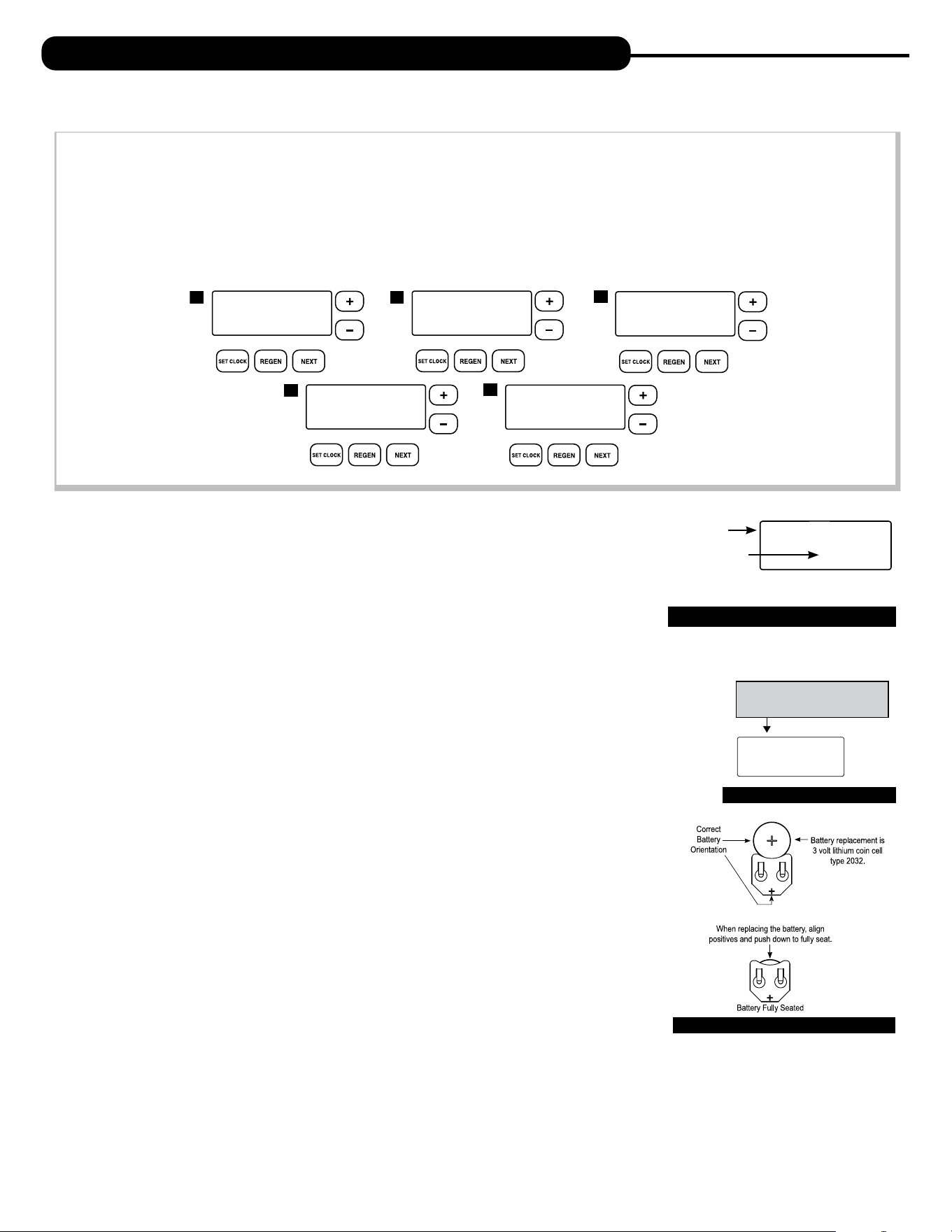
4. POWER LOSS AND BATTERY REPLACEMENT: If an extended power outage occurs, the control
valve will retain the time of day settings until the board’s battery is depleted. Once the battery is
depleted, the display will appear dark and absent of any information. If this occurs, following these steps
will determine if the problem is a low battery or a board failure.
To determine if the battery is depleted:
1. Remove valve cover. Disconnect power from PC Board at the four pin connector at the bottom
of the board.
2. Wait five minutes for board to de-energize. Remove battery with a non-conductive/non-metallic
material. Reference the Parts Breakdown section of this manual for location.
3. Wait five minutes for board to de-energize.
4. With the battery out, re-connect the power supply to the board. The board’s display should
begin to show information.
This indicates that the board is operating correctly. If the display does not work, call installing dealer for service.
5. To replace with new battery, unplug transformer from outlet. Install a 3 volt Lithium Coin Cell type 2032 battery, available at most stores.
Plug unit back into outlet.
It is important to replace the battery with the valve unplugged to avoid causing a short and potentially ruining the board.
6. Reset the time of day (see programming procedures) and initiate regeneration (see operating displays and maintenance).
If these procedures do not remedy the problem, please consult the installing dealer for service.
REGENERATION MODE
BACKWASH
8:22
Current Regen
Cycle Stage
Time Remaining
in Stage
MANUAL REGEN
REGEN TODAY MON
GPM
2:408
PM
REGEN TODAY and TIME OF DAY
will ash alternately if a regeneration
is expected tonight.
TIME OF DAY MON
GPM
2:40A
PM
1
FLOW RATE
GPM
8.0
A
CAPACITY REMAINING
GPM GAL
1600
A
DAYS TO A REGEN
GPM
3
A
555 5555555
DEALER NA
4
2
5
3
BATTERY REPLACEMENT

10
OPERATING DISPLAYS AND MAINTENANCE:
5. ERROR MESSAGE: If the word “ERROR” appears and flashes alternately with the dealer name and phone
number, record the ERROR number and contact your servicing dealer promptly. This indicates that the control
valve was not able to function properly.
6. BRINE TANK MAINTENANCE AND SALT: Refill the brine tank as necessary, making sure at least 1/3 of the
brine tank is full at all times. Without proper salt levels, the water softener may not operate properly.
Because “typical” settings of this water softener include a dry salt storage feature (a small amount of water in brine tank between regeneration),
the manufacturer recommends the use of solar salt for best results. The brine tank is manufactured for the use of solar, pellets or rock salt. Do
not use block salt. If pellet or rock salt is used, a cleaning of the brine tank every six months is recommended. If the dry salt storage feature is not
being utilized, block salt may be used.
CAUTION: With some models the manufacturer does NOT recommend the use of any resin cleaners, nor placing any resin cleaners
into the brine tank. Furthermore, do not use any salt that indicates it is an iron cleaning salt or that contains any cleaning
additives. This may be harmful to the water softener and for human consumption. Consult dealer for proper cleaning
instructions.
ERROR SCREEN
ERROR
106
CALL FOR SERVICE
10 11
PROBLEM CAUSE CORRECTION
1. No display on
PC board.
A. Depleted battery. A. See Operating Display and Maintenance section.
B. Control valve power adapter not plugged into outlet
or power cord end not connected to PC board
connection.
B. Plug power adapter into outlet or connect
power cord end to PC board connection.
C. Improper power supply.
C. Verify proper voltage is being delivered to
PC board.
D. Defective power adapter. D. Replace power adapter.
E. Defective PC board. E. Replace PC board.
F. No power at electric outlet.
F. Repair outlet or use working outlet.
2. PC board does not
display correct time
of day.
A. Power adapter plugged into electric outlet controlled
by light switch.
A. Use uninterrupted outlet.
B. Tripped breaker switch and/or tripped GFI. B. Reset breaker switch and/or GFI switch.
C. Power outage.
C. Reset time of day. If PC board has battery
back up present the battery may be depleted. See
front cover and drive assembly drawing
for instructions.
D. Defective PC board. D. Replace PC board.
3. Display does not
indicate that water is
flowing. Refer to user
instructions for how
the display indicates
water is flowing.
A. Bypass valve in bypass position.
A. Turn bypass handles to place bypass in
service position.
B. Meter is not connected to meter connection on PC
board.
B. Connect meter to three pin connection labeled
METER on PC board.
C. Restricted/stalled meter turbine.
C. Remove meter and check for rotation or
foreign material.
D. Meter wire not installed securely into three
pin connector.
D. Verify meter cable wires are installed securely into
three pin connector labeled METER.
E. Defective meter. E. Replace meter.
F. Defective PC board. F. Replace PC board.
4. Control valve
regenerates at wrong
time of day.
A. Power outage.
A. Reset time of day. If PC board has battery
back up present the battery may be depleted. See
front cover and drive assembly drawing
for instructions.
B. Time of day not set correctly. B. Reset to correct time of day.
C. Time of regeneration set incorrectly. C. Reset regeneration time.
D. Control valve set at immediate regeneration.
D. Check programming setting and reset to DELAYED
(for a delayed regen time).
5. Time of day flashes on
and off.
A. Power outage.
A. Reset time of day. If PC board has battery
back up present the battery may be depleted. See
front cover and drive assembly drawing
for instructions.
6. Control valve does
not regenerate
automatically when
the correct button(s) is
pressed and held.
For timeclock valves
the buttons are
+ or –.
For all other valves the
button is REGEN.
A. Broken drive gear or drive cap assembly. A. Replace drive gear or drive cap assembly.
B. Broken piston rod. B. Replace piston rod.
C. Defective PC board. C. Defective PC board.
D. Cover installed incorrectly. D. Reinstall cover.
TROUBLESHOOTING GUIDE
12
7. Control valve does
not regenerate
automatically but
does when the correct
button(s) is depressed
and held. For
timeclock valves the
buttons are
+ or –.
For all other valves the
button is REGEN.
A. Bypass valve in bypass position.
A. Turn bypass handles to place bypass in
service position.
B. Meter is not connected to meter connection on PC
board.
B. Connect meter to three pin connection labeled
METER on PC board.
C. Restricted/stalled meter turbine.
C. Remove meter and check for rotation or
foreign material.
D. Incorrect programming. D. Check for programming error.
E. Meter wire not installed securely into three
pin connector.
E. Verify meter cable wires are installed securely into
three pin connector labeled METER.
F. Defective meter. F. Replace meter.
G. Defective PC board. G. Replace PC board.
8. Hard or untreated
water is being
delivered.
A. Bypass valve is open or faulty. A. Fully close bypass valve or replace.
B. Media is exhausted due to high water usage.
B. Check program settings or diagnostics for abnormal
water usage.
C. Meter not registering.
C. Remove meter and check for rotation or
foreign material.
D. Water quality fluctuation.
D. Test water and adjust program
values accordingly.
E. No regenerant or low level of regenerant in
regenerant tank.
E. Add proper regenerant to tank.
F. Control fails to draw in regenerant. F. Refer to Troubleshooting Guide number 12.
G. Insufficient regenerant level in regenerant tank.
G. Check refill setting in programming. Check refill
flow control for restrictions or debris and, if
necessary, replace.
H. Damaged seal/stack assembly/piston. H. Replace seal/stack assembly and/or piston.
I. Control valve body type and piston type
mix matched.
I. Verify proper control valve body type and
piston type match.
J. Fouled media bed. J. Replace media bed.
9. Control valve uses
too much regenerant.
A. Improper refill setting. A. Check refill setting.
B. Improper program settings.
B. Check program setting to make sure
they are specific to the water quality and
application needs.
C. Control valve regenerates frequently.
C. Check for leaking fixtures that may be exhausting
capacity or system is undersized.
10. Residual regenerant
being delivered to
service.
A. Low water pressure.
A. Check incoming water pressure – water pressure
must remain at minimum of 25 psi.
B. Incorrect, damaged, or restricted injector.
B. Replace injector with correct size for
the application.
C. Restricted drain line.
C. Check drain line for restrictions or debris
and remove any obstructions.
11. Excessive water in
regenerant tank.
A. Improper program settings. A. Check refill setting.
B. Plugged injector. B. Remove injector and replace.
C. Drive cap assembly not tightened in properly. C. Re-tighten the drive cap assembly.
D. Damaged seal/stack assembly/piston. D. Replace seal/stack assembly and/or piston.
E. Restricted or kinked drain line.
E. Check drain line for restrictions or debris and or
unkink drain line.
F. Plugged backwash flow controller.
F. Remove backwash flow controller and replace, if
necessary.
G. Missing refill flow controller. G. Install refill flow controller.
H. Brine tube not inserted properly into brine elbow in
brine tank.
H. Install tube all the way into elbow.
PROBLEM CAUSE CORRECTION
TROUBLESHOOTING GUIDE
12 13
TROUBLESHOOTING GUIDE
12. Control valve fails to
draw in regenerant.
A. Injector is plugged. A. Remove injector and replace.
B. Faulty regenerant piston. B. Replace regenerant piston.
C. Regenerant line connection leak. C. Inspect regenerant line for air leak.
D. Drain line restriction or debris cause excess back
pressure.
D. Inspect drain line and remove to
correct restriction.
E. Drain line too long or too high. E. Shorten length and or height.
F. Low water pressure.
F. Check incoming water pressure – water
pressure must remain at minimum of 25 psi.
13. Water running to
drain.
A. Power outage during regeneration.
A. Upon power being restored control will finish
the remaining regeneration time. Reset time of
day. If PC board has battery back up present the
battery may be depleted. See front cover and drive
assembly drawing for instructions.
B. Damaged seal/stack assembly. B. Replace seal/stack assembly.
C. Piston assembly failure. C. Replace piston assembly.
D. Drive cap assembly not tightened in properly. D. Re-tighten the drive cap assembly.
14. E1, Err – 1001,
Err – 101 =
Control unable
to sense motor
movement.
A. Motor not inserted full to engage pinion, motor
wires broken or disconnected.
A. Disconnect power, make sure motor is fully engaged,
check for broken wires, make sure
two pin connector on motor is connected to the two
pin connection on the PC board labeled MOTOR.
Press NEXT and REGEN buttons for
3 seconds to resynchronize software with piston
position or disconnect power supply from PC board
for 5 seconds and then reconnect.
B. PC board not properly snapped into drive bracket.
B. Properly snap PC board into drive bracket and
then Press NEXT and REGEN buttons for 3 seconds
to resynchronize software with piston position
or disconnect power supply from PC board for 5
seconds and then reconnect.
C. Missing drive gears. C. Replace missing gears.
D. Motor does not drive/run. D. Replace motor.
E. Viewing eye or encoder is blocked or damaged.
E. clear viewing eye on board, on drive bracket, or
replace PC board if no debris is found.
15. E2, Err – 1002,
Err – 102 = Excessive
Motor Draw.
A. Foreign material is lodged in control valve.
A. Open up control valve and pull out piston assembly
and seal/stack assembly for inspection. Press NEXT
and REGEN buttons for
3 seconds to resynchronize software with piston
position or disconnect power supply from PC board
for 5 seconds and then reconnect.
B. Mechanical binding.
B. Check piston and seal/stack assembly, check
reduction gears, check drive bracket and main drive
gear interface. Press NEXT and REGEN buttons for
3 seconds to resynchronize software with piston
position or disconnect power supply from PC board
for 5 seconds and then reconnect.
C. Drive cap too loose. C. Completely tighten drive cap assembly.
D. Drive cap not “clicked” into backplate.
D. Verify that backplate is properly “clicked” into
place.
PROBLEM CAUSE CORRECTION
14
16. E3, Err – 1003,
Err – 103 = Control
valve motor ran
too long and was
unable to find the
next cycle position.
A. Drive bracket not snapped in properly and out
enough that reduction gears and drive gear do not
interface.
A. Snap drive bracket in properly then Press
NEXT and REGEN buttons for 3 seconds to
resynchronize software with piston position
or disconnect power supply from PC board
for 5 seconds and then reconnect.
17. E4, Err – 1004,
Err – 104 = Control
valve motor ran too
long and timed out
trying to reach home
position.
A. Drive bracket not snapped in properly and out enough
that reduction gears and drive gear do
not interface.
A. Snap drive bracket in properly then Press
NEXT and REGEN buttons for 3 seconds to
resynchronize software with piston position
or disconnect power supply from PC board
for 5 seconds and then reconnect.
B. Piston not connected to drive cap. B. Connect or replace (if damaged) piston/drive cap.
18. Err – 1006, Err – 106,
Err – 116 = MAV/
SEPS/ NHBP/ AUX
MAV valve motor
ran too long and
unable to find
the proper park
position.
●Motorized Alternating Valve = MAV
●Separate Source = SEPS
●No Hard Water Bypass = NHBP
●Auxiliary MAV = AUX MAV
A. Control valve programmed for ALT A or B,
nHbP, SEPS, or AUX MAV with out having
a MAV or NHBP valve attached to operate
that function.
A. Press NEXT and REGEN buttons for 3 seconds
to resynchronize software with piston position
or disconnect power supply from PC board for
5 seconds and then reconnect. Then reprogram valve
to proper setting.
B. MAV/NHBP motor wire not connected to
PC board.
B. Connect MAV/NHBP motor to PC board two pin
connection labeled DRIVE. Press NEXT and REGEN
buttons for 3 seconds to resynchronize software
with piston position or disconnect power supply
from PC board for 5 seconds
and then reconnect.
C. MAV/NHBP motor not fully engaged with reduction
gears.
C. Properly insert motor into casing, do not force into
casing Press NEXT and REGEN buttons for
3 seconds to resynchronize software with piston
position or disconnect power supply from PC board
for 5 seconds and then reconnect.
D. Foreign matter built up on piston and stack
assemblies creating friction and drag enough
to time out motor.
D. Replace piston and stack assemblies. Press NEXT
and REGEN buttons for 3 seconds to resynchronize
software with piston position
or disconnect power supply from PC board
for 5 seconds and then reconnect.
19. Err – 1007, Err –
107, Err – 117 =
MAV/ SEPS/NHBP/
AUX MAV valve
motor ran too short
(stalled) while
looking for proper
park position.
●Motorized Alternating Valve = MAV
●Separate Source = SEPS
●No Hard Water Bypass = NHBP
●Auxiliary MAV = AUX MAV
A. Foreign material is lodged in
MAV/NHBP valve.
A. Open up MAV/NHBP valve and check piston and
seal/ stack assembly for foreign material. Press NEXT
and REGEN buttons for 3 seconds
to resynchronize software with piston position
or disconnect power supply from PC board for
5 seconds and then reconnect.
B. Mechanical binding.
B. Check piston and seal/stack assembly, check
reduction gears, drive gear interface, and check
MAV/NHBP black drive pinion on
motor for being jammed into motor body.
Press NEXT and REGEN buttons for 3 seconds to
resynchronize software with piston position or
disconnect power supply from PC board for 5
seconds and then reconnect.
PROBLEM CAUSE CORRECTION
TROUBLESHOOTING GUIDE

14 15
PROBLEM CAUSE CORRECTION
20. Err – 201
200 errors are only
viewable in history
screens. These do not
flash when error occurs.
A. Invalid regeneration cycle step detected. A. Replace PC board.
21. Err – 202
200 errors are only
viewable in history
screens. These do not
flash when error occurs.
A. Short power disruption. A. Check transformer voltage and verify power source.
B. Foreign material dislodged. B. Check piston and stack for damage.
22. Err – 204 = Leak
detected
200 errors are only
viewable in history
screens. These do not
flash when error occurs.
A. Occurs when dP input is active for “ALARM” and the
input is closed. The alarm buzzer will activate and the
screen will display the error.
A. Check for low flow leak. Press NEXT and REGEN
buttons for 3 seconds to resynchronize software
with piston position or disconnect power supply
from PC Board for 5 seconds
and then reconnect to clear error.
23. Err – 400
*
Memory Errors
*All 400 errors pertain to
memory related errors.
400 and 200 errors are
only viewable in history
screens. These do not
flash when error occurs.
A. Depleted Battery. A. See Operating Display and Maintenance section.
B. Defective PC Board. B. Replace PC board.
TROUBLESHOOTING GUIDE

16
This page intentionally left blank.

16 17
This page intentionally left blank.
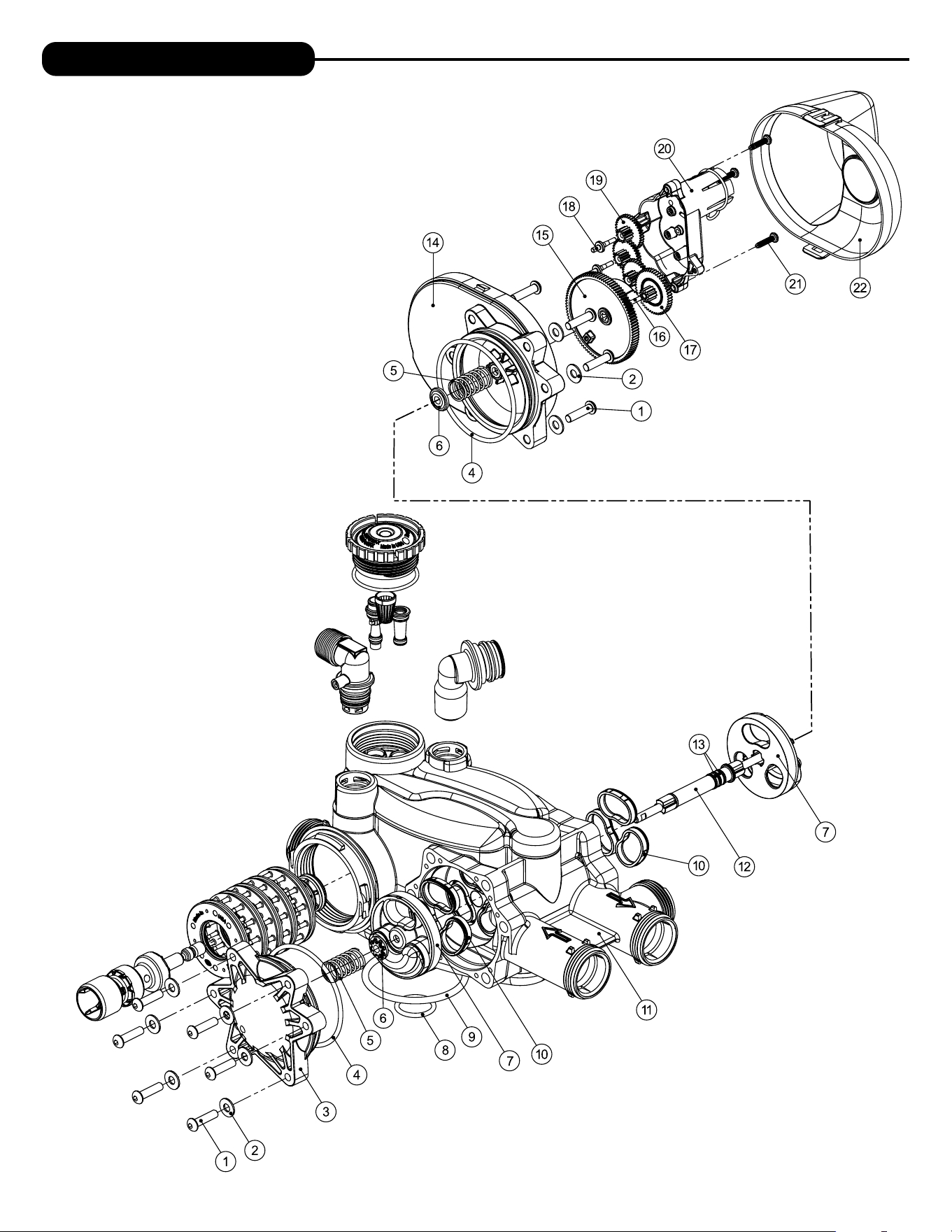
18
REPLACEMENT PARTS
NOTE: Battery Location
1
2
3
5
6
4
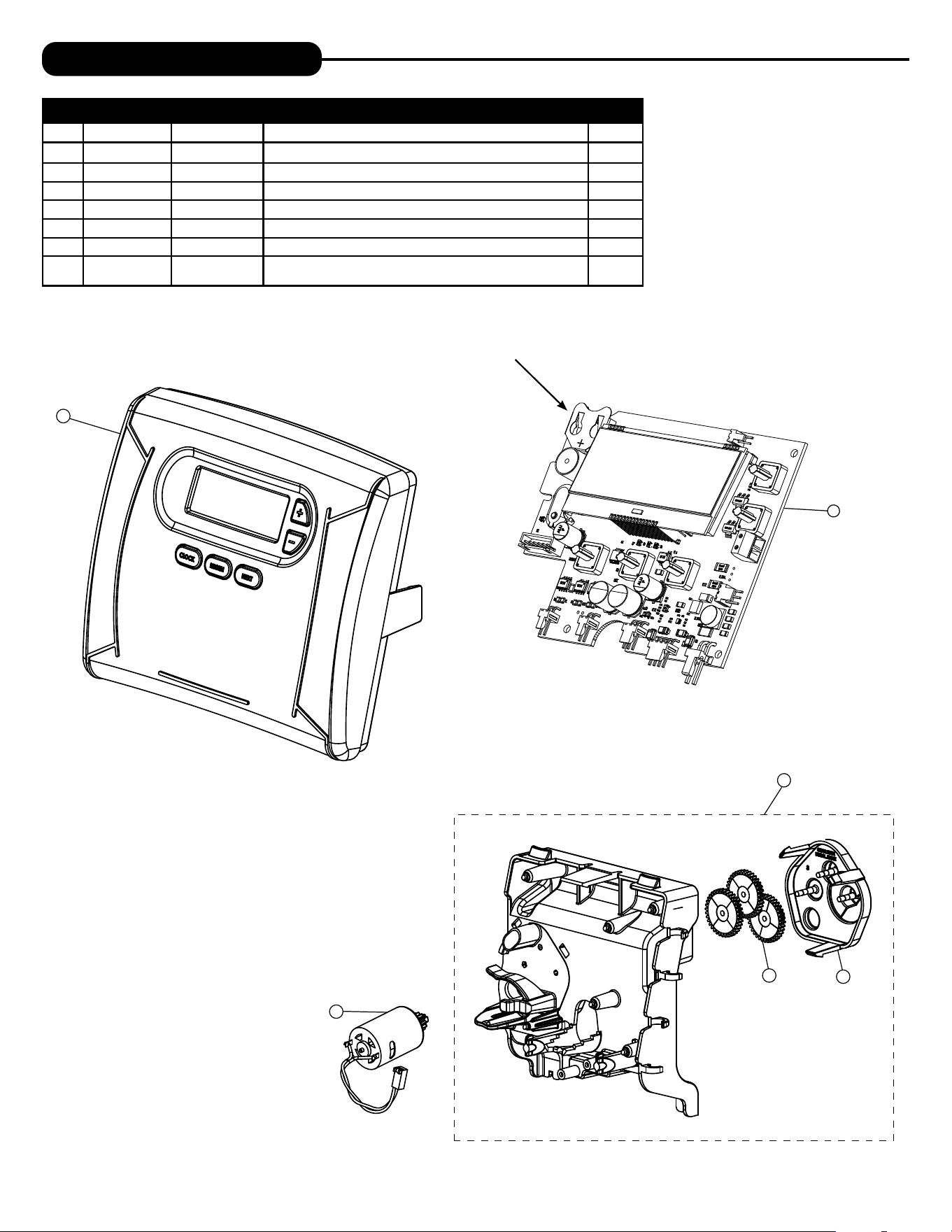
FRONT COVER AND DRIVE ASSEMBLY
Item # Legacy Part # Current Part # Description Qty.
1 CV4637-01 100379001 Valve cover 1
2 CV3107-1 100246273 Motor Assembly 1
3 CV3002-A 100246193 Drive assembly (includes #5 and #6) —
4 CV4229XP-03 100243791 PC board 1
5 CV3110 100246279 Drive gear, 12 x 36 3
6 CV3109 100246278 Drive gear cover 1
not
shown
CV3186-06 100249863 Transformer, 110V-12V, AC (standard) 1
18 19
1
2
3
4
5
6
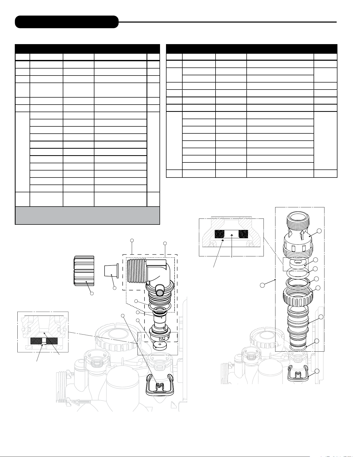
REPLACEMENT PARTS
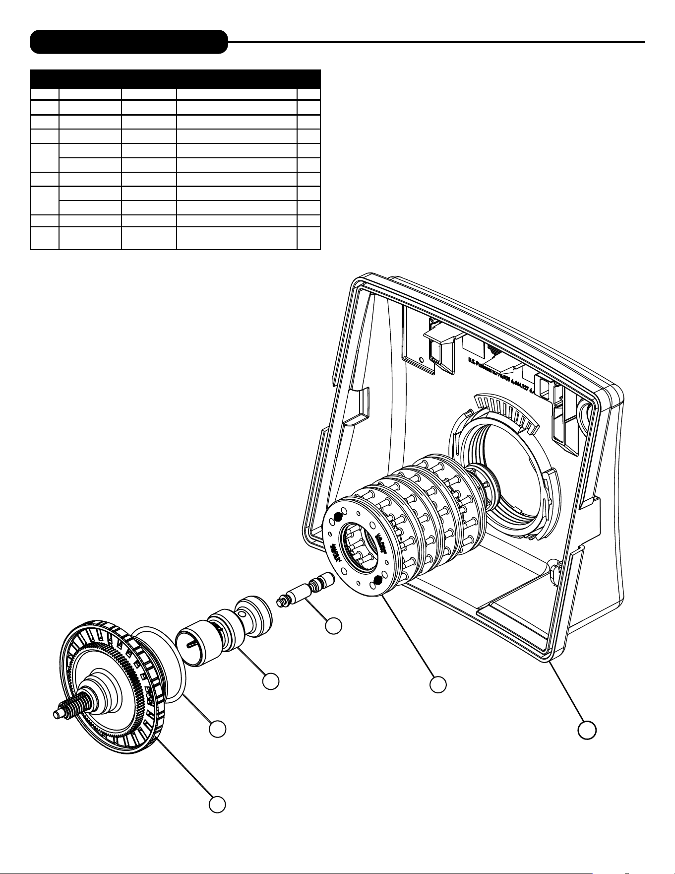
PISTON ASSEMBLY
Item # Legacy Part # Current Part # Description Qty.
1 CV3005-02 100249844 1” spacer stack assembly 1
2 CV3004 100246196 Drive cap assembly 1
3 CV3135 100246281 O-ring 228 (drive cap o-ring) 1
4
CV3011 100246232 1” piston assembly downflow 1
CV3011-01 100246233 1” piston assembly upflow 1
5 CV3174 100246296 Regenerant piston 1
Not
shown
CV3001-04 100244557 1” body assembly downflow 1
CV3001-04UP 100243827 1” body assembly upflow 1
6 CV3541 100249867 Drive backplate 1
Not
Shown
CD1225-05 100249834 Top basket softener (optional)
20
REPLACEMENT PARTS
20 21
REPLACEMENT PARTS
TWIN TRANSFER
Item #. Legacy Part # Current Part # Description Qty.
1 CV3470 100343288 Screw, BHC 1/4-20 x 1 SS 12
2 CV3724 100173781 Washer, flat SS 1/4 12
3 CV4005-01 100358458 T1 transfer cap assembly 1
4 CV4029 100246440 O-ring 236 2
5 CV4015 100343287 T1 transfer spring 2
6 CV4014 100246434 T1 transfer spring support 2
7 CV4036 100246441 T1 rotor disk assembly 2
8 CV3105 100246272 O-ring 215 (distributor tube) 1
9 CV3180 100246307 O-ring 337 1
10 CV4016 100246435 T1 transfer seal 6
11 CV3031 100358457 T1 body sft wtr regen 1
12 CV4023 100246439 T1 transfer drive shaft assembly 1
13 CV3287 100246338 O-ring 110 2
14 CV4006-01 100358456 T1 transfer drive cap assembly 1
15 CV4011-01 100343285 T1 transfer drive gear assembly 1
16 CV4012 100358455 T1 transfer drive gear axle 1
17 CV4013 100246433 T1 transfer reduction gear 1
18 CV3264 100244912 WS2H bypass reduction gear axle 3
19 CV3110 100246279 WS1 drive reducing gear 12 x 36 3
20 CV3262-01 100244508 WS1.5 & 2 ALT/2BY reduction gear cover assembly 1
21 CV3592 100246388 Screw, #8-1 PHPN T-25 SS 3
22 CV4049 100358178 T1 cover assembly 1
not shown CV4043 100246443 T1 transfer motor assembly 1
not shown CV3151 100246287 WS1 nut 1 QC 1
not shown CV4055* 100246446 Twin tank meter assembly 1
not shown CV4017-01 100246436 T1 interconnect fitting assembly 1
not shown CD1400 100245769 1191 In/Out head 1
not shown CD1225-05 100249834 Top basket softener (optional) 1
*This water meter should not be used as the primary monitoring device
for critical or health effect applications.
22
REPLACEMENT PARTS
4
2
31
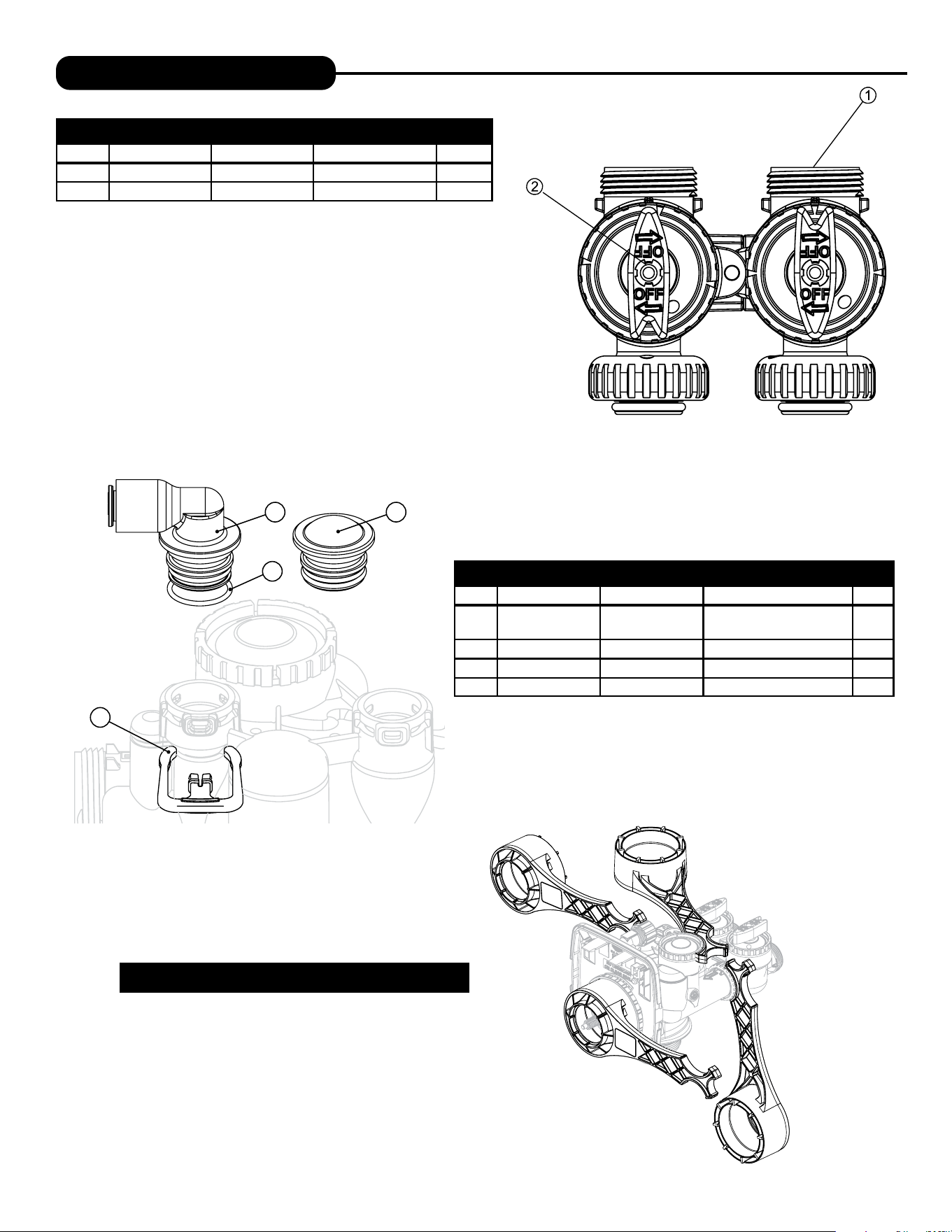
REFILL PORT ASSEMBLY
Item # Legacy Part # Current Part # Description Qty.
1 CV4144 100245015
3/8” Elbow, Parker fitting with
O-ring 019
1
2 CV3163 100246291 O-ring 019 1
3 CV3195-01 100246323 Refill port plug assembly 1
4 CH4615 100245862 Elbow locking clip 1
BYPASS VALVE
Item #. Legacy Part # Current Part # Description Qty.
1 CV3006 100249845 Bypass assembly 1
2 CV3147 100246284 Bypass handles 2
Loosens Injector And
Bypass Caps
Loosens Drive Cap
Although no tools are necessary to assemble or disassemble the
valve, the Service Wrench, (shown in various positions on the valve)
is available to aid in assembly or disassembly.
SERVICE WRENCH - 100249864 (CV3193-02)
22 23
INJECTOR ASSEMBLIES
Item # Legacy Part # Current Part # Description Qty.
1 CV3176 100246304 Injector cap 1
2 CV3152 100244507 O-ring 135 1
3 CV3177-01 100246305 Injector screen 1
4 CV3010-1Z 100246221 Injector assembly plug 1
5
CV3010-1A 100246211 A injector assembly, �����
1
CV3010-1B 100246212 B injector assembly, �����
CV3010-1C 100246213 C injector assembly, ������
CV3010-1D 100249849 D injector assembly, ���
CV3010-1E 100246214 E injector assembly, �����
CV3010-1F 100246215 F injector assembly, ����
CV3010-1G 100246216 G injector assembly, ������
CV3010-1H 100246217 H injector assembly, �����
CV3010-1I 100246218 I injector assembly, ������
CV3010-1J 100246219 J injector assembly, ����� ����
CV3010-1K 100246220 K injector assembly, ����� �����
*The injector plug and the injector each use one lower and one upper o-ring
REPLACEMENT PARTS
3
1
2
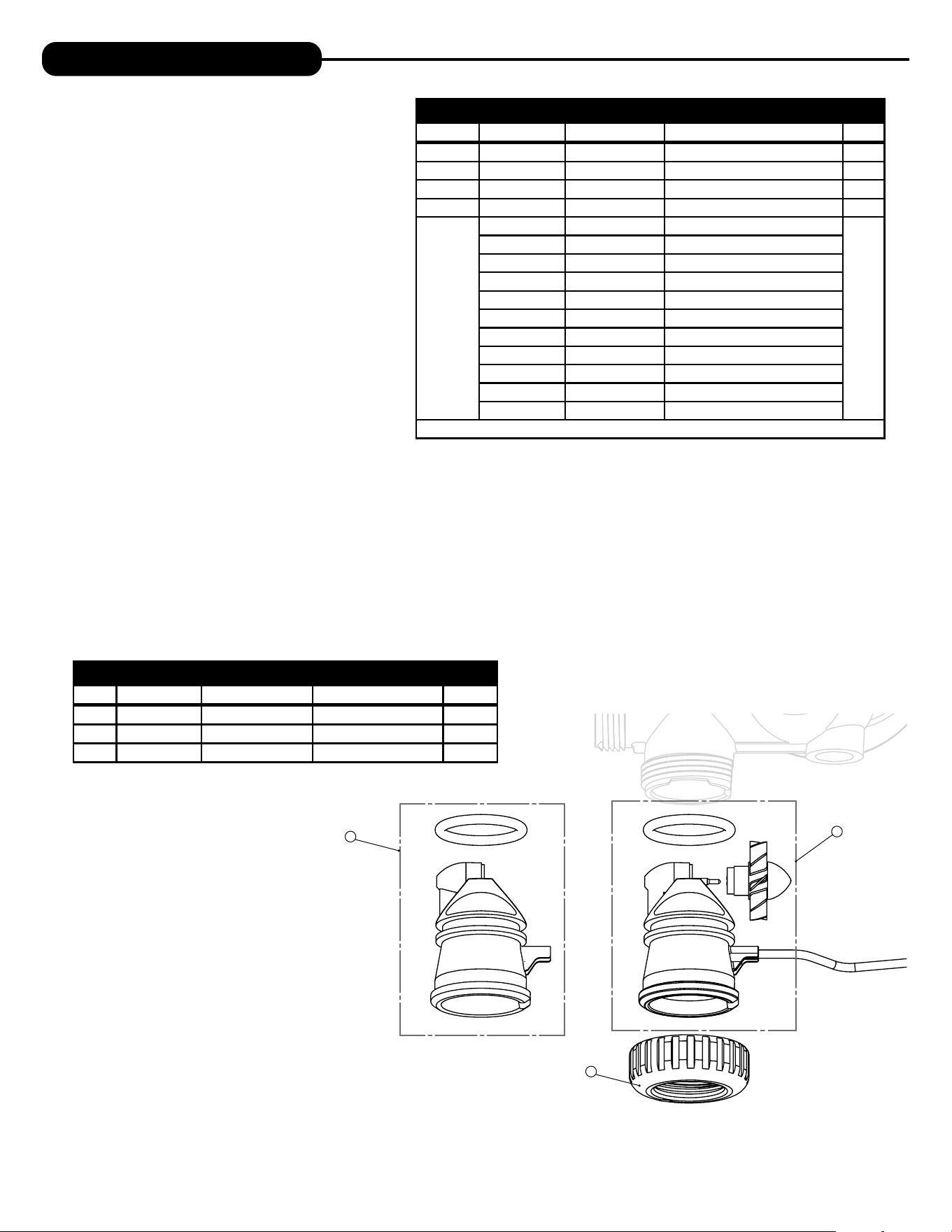
WATER METER AND METER PLUG
Item # Legacy Part # Current Part # Description Qty.
1 CV3151 100246287 Nut, 1” Quick Connect 1
2 CV3003 100253284 Meter assembly 1
3 CV3003-01 100246195 Meter plug assembly 1
24
REPLACEMENT PARTS
Water
Flow
5
8
Drain
Line
1”
4
6
7
Proper DLFC orientation
directs water flow towards
the washer face with
rounded edge.
3
1
2
2
DRAIN LINE ASSEMBLY 1”
Item # Legacy Part # Current Part # Description Qty.
1 CH4615 100245862 Elbow locking clip 1
2
CV3166 100246292 Drain FTG body 1
1
CV3166-01 100246293 FTG flow control body 1
3 CV3163 100246291 O-ring 019 1
4 CV3150 100246286 Split ring 1
5 CV3151 100246287 Nut 1" QC 1
6 CV3105 100246272 O-ring 215
7
CV3190-090 100246313 9.0 gpm DLFC for 1” elbow
One DLFC
must be used
if 1" fitting is
used
CV3190-100 100246314 10.0 gpm DLFC for 1” elbow
CV3190-110 100246315 11.0 gpm DLFC for 1” elbow
CV3190-130 100246316 13.0 gpm DLFC for 1” elbow
CV3190-150 100246317 15.0 gpm DLFC for 1” elbow
CV3190-170 100246318 17.0 gpm DLFC for 1” elbow
CV3190-200 100246319 20.0 gpm DLFC for 1” elbow
CV3190-250 100246320 25.0 gpm DLFC for 1” elbow
8 CV3008-04 100243824 FTG Drain 1" Strt No/Silencer 1
Water flow
Proper DLFC orientation
directs water flow towards
the washer face with
rounded edge.
2
3
8
5
7
6
1
4
DRAIN LINE ASSEMBLY 3/4”
Item # Legacy Part # Current Part # Description Qty.
1 CH4615 100245862 Elbow locking clip 1
2 CPKP10TS8-BULK 100245919 Optional insert, 5/8” tube 1
3 CV3192 100246322 Optional nut, 3/4” drain elbow 1
4 CV3158-02 100249851
Drain elbow, 3/4” NPT with
O-ring
1
5 CV3163 100246291 O-ring 019 1
6 CV3159-01 100246290 DLFC retainer assembly 1
7
CV3162-007 100244908 0.7 DLFC for 3/4” elbow
1
CV3162-010 100244909 1.0 DLFC for 3/4” elbow
CV3162-013 100244910 1.3 DLFC for 3/4” elbow
CV3162-017 100244911 1.7 DLFC for 3/4” elbow
CV3162-022 100249852 2.2 DLFC for 3/4” elbow
CV3162-027 100249853 2.7 DLFC for 3/4” elbow
CV3162-032 100249854 3.2 DLFC for 3/4” elbow
CV3162-042 100249855 4.2 DLFC for 3/4” elbow
CV3162-053 100249856 5.3 DLFC for 3/4” elbow
CV3162-065 100249857 6.5 DLFC for3/4” elbow
CV3162-075 100249858 7.5 DLFC for 3/4” elbow
8 CV3331A 100245051
Drain elbow and retainer
assembly
Items 2 and 3, nut and insert are only used with 1/2” I.D. by 5/8” O.D. polytubing.
For other piping material, the 3/4” NPT is used.
24 25
REPLACEMENT PARTS
1
2
3
4
5
6
7
9
2
3
4
1
8
10
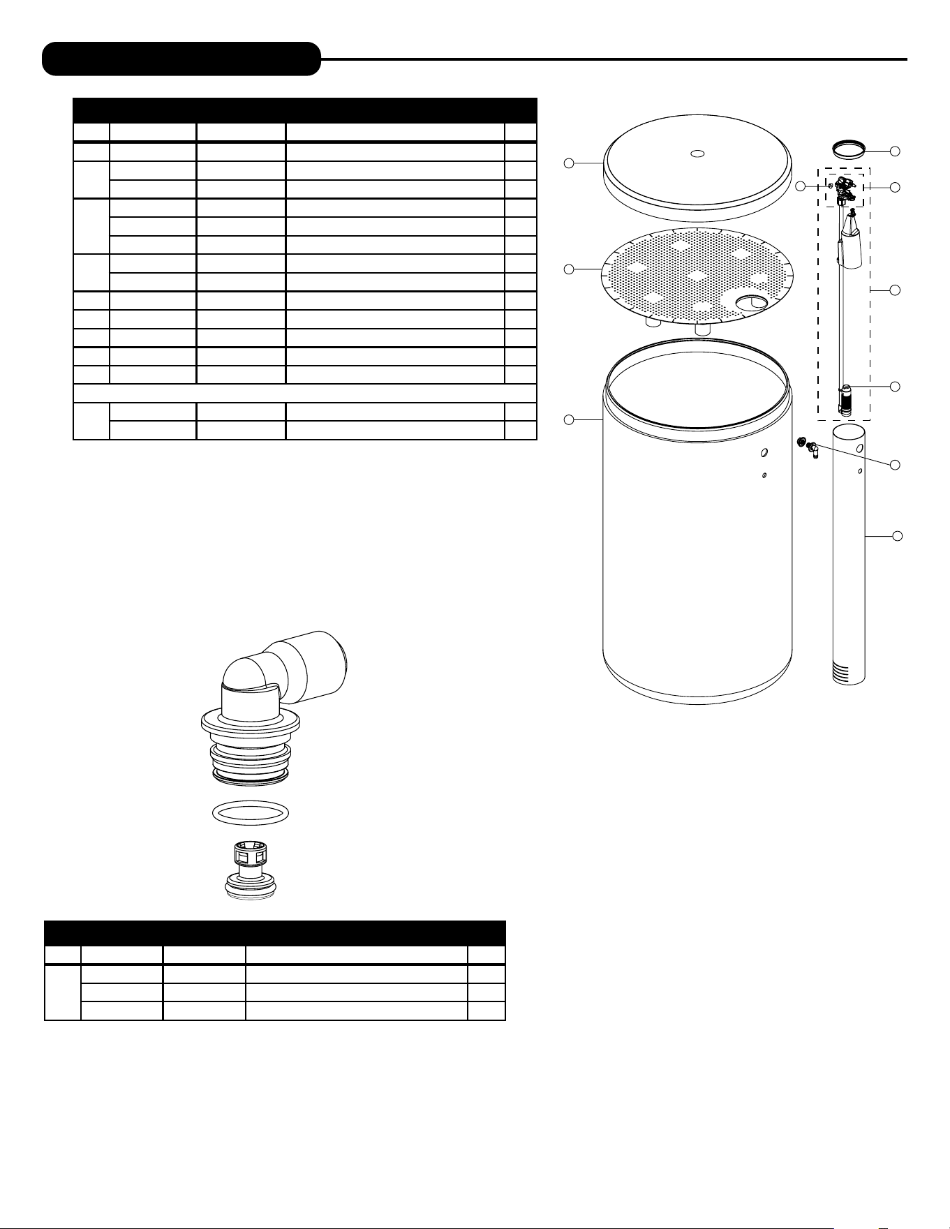
BRINE TANK ASSEMBLY (AO)
Item # Legacy Part # Current Part # Description Qty.
1 CG2191-112 100253161 Brine tank cover, injection molded AO 1
2
CH1095-01 100245856 Optional 18” diameter salt grid 1
CH1080 100245853 Optional 24” diameter salt grid 1
3
BT1833-1A 100245568 18” x 33” brine tank assembly 1
BT1840-1A 100245574 18 ”
x 40” brine tank
assembly 1
BT2441-1A 100245576 24” x 41” brine tank assembly 1
4
CH1030-29S 100245837 4” x 29” slotted brine well (18 x 33 BT) 1
CH1030-36S 100245841 4” x 36” slotted brine well (18 x 40, 24 x 40 BTs) 1
5 CH1018 100245836 2 piece overflow set 1
6 CH4500-48 100245857 474 air check assembly, 1/2” x 48” 1
7 CH4600-50 100245860 474 safety brine valve w/ .5 gpm flow control 1
8 CH7016 100245880 Cap 4” brine well 1
9 CH4626 100245864 Nut safety brine valve stand off 1
Assemblies
10
CH4700-29WR-1 100244899 .5 gpm safety float assembly, 18” x 33”
CH4700-36.5WR-1 100245872 .5 gpm safety float assembly, 18” x 40”
SAFETY FLOAT BRINE ELBOW
Item # Legacy Part # Current Part # Description Qty.
CV4144 100245015 3/8” elbow cap, Parker fitting (no flow control) 1
CV4144-03 100242646 3/8” elbow cap, Parker fitting (w/flow control) 1
CH4612 100245861 1/2” elbow cap 1
26
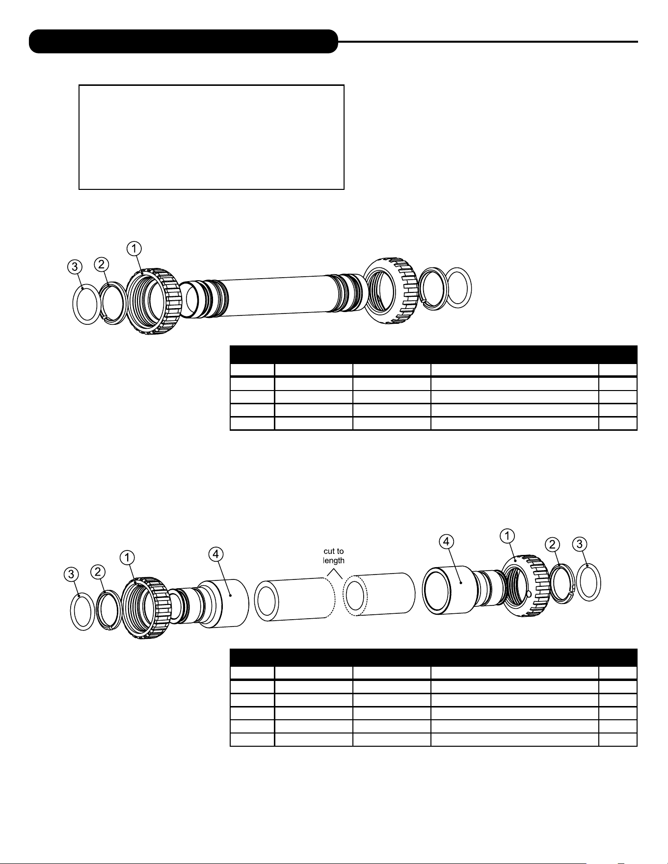
INSTALLATION FITTING ASSEMBLIES
INTERCONNECT FITTING ASSEMBLY (UP TO 10” TANKS)
Item # Legacy Part # Current Part # Description Qty.
CV4017-01 100246436 Interconnect kit for tanks up to 10” 1
1 CV3151 100246287 Nut, 1” QC 4
2 CV3150 100246286 Split ring 4
3 CV3105 100246272 O-ring 215 4
INTERCONNECT FITTING ASSEMBLY (12” & LARGER TANKS)
Item # Legacy Part # Current Part # Description Qty.
CV4052-01 100246445 Interconnect kit for tanks 12” and larger 1
1 CV3151 100246287 Nut, 1” QC 4
2 CV3150 100246286 Split ring 4
3 CV3105 100246272 O-ring 215 4
4 CV3352 100244126 1-1/4” & 1-1/2” PVC solvent fitting 4
Fitting Installation Instructions
• Installation fittings are designed to accommodate minor plumbing
misalignments, but are not designed to support the weight of a
system or the plumbing.
• Slide nut on first, then the split ring and O-ring.
• Hand tighten the nut only.
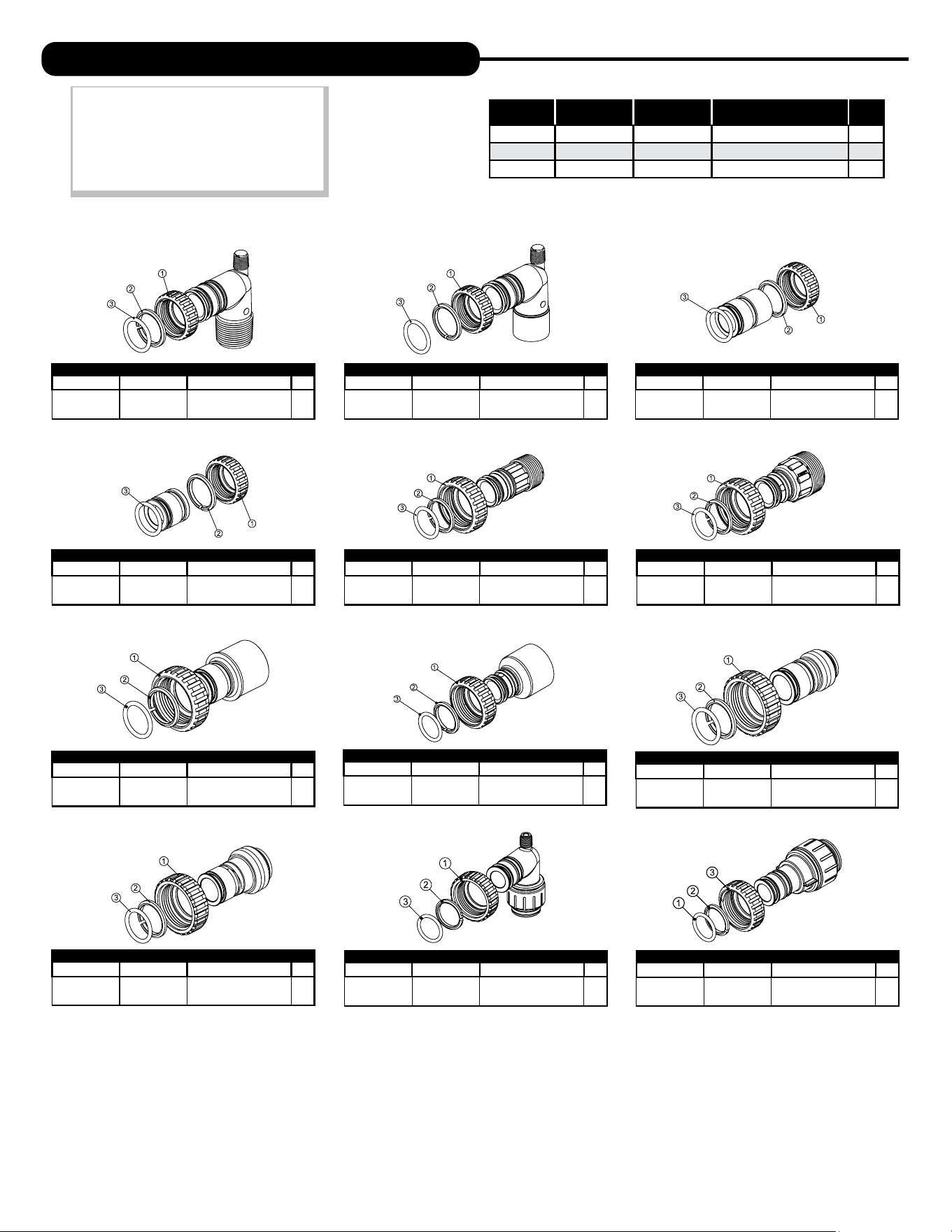
26 27
Legacy Part # Current Part # Description Qty.
CV3007 100246197
1” PVC male NPT
elbow assembly
2
Legacy Part # Current Part # Description Qty.
CV3007-01 100246198
3/4” & 1” PVC solvent
elbow assembly
2
Legacy Part # Current Part # Description Qty.
CV3007-02 100246199
1” brass sweat
assembly
2
Legacy Part # Current Part # Description Qty.
CV3007-03 100249846
3/4” brass
sweat assembly
2
Legacy Part # Current Part # Description Qty.
CV3007-12 100249847
3/4” brass shark
bite assembly
2
Legacy Part # Current Part # Description Qty.
CV3007-13 100249848
1” brass shark
bite assembly
2
Legacy Part # Current Part # Description Qty.
CV3007-15 100246200
3/4” john guest
elbow assembly
2
Legacy Part # Current Part # Description Qty.
CV3007-17 100245045
1” john guest
assembly
2
Legacy Part # Current Part # Description Qty.
CV3007-09 100243922
1-1/4” & 1-1/2” brass
sweat assembly
2
Legacy Part # Current Part # Description Qty.
CV3007-07 100243375
1-1/4” & 1-1/2” PVC
solvent assembly
2
Legacy Part # Current Part # Description Qty.
CV3007-04 100244506
1” plastic male NPT
assembly
2
Legacy Part # Current Part # Description Qty.
CV3007-05 100243921
1-1/4” plastic male
assembly
2
Item # Legacy Part # Current Part # Description Qty.
1 CV3151 100246287 Nut, 1” quick connect 2
2 CV3150 100246286 Split ring 2
3 CV3105 100246272 O-ring 215 2
NOTE: Not all available ttings are
displayed below. Contact
manufacturer for optional
ttings.
For All Assemblies
INSTALLATION FITTING ASSEMBLIES

28
This page intentionally left blank.
28 29
TWIN SOFTENER SPECIFICATIONS
Cycle Times and Salt Usage
Twin Series Softeners
Specifications
MODEL
APR-1054TW
1
Capacity:*
(Grains/Lbs. NaCl)
Minimum
35,400 @ 9.0
Medium
44,400 @ 15.0
Maximum
48,800 @ 21.0
Amount of Resin Media (Cu. Ft.) 1.5
Maximum Water Hardness (GPG) 100
2
Minimum pH Required 7.0
3
Peak Flow Rate (GPM @ P-PSI) 14.3 @ 15.0
Continuous Flow Rate (GPM @ P-PSI) 5.0 @ 3.8
Water Pressure Range (PSI) 30-100
Water Temperature (ºF) 33-100
Electrical Requirements (volts-hertz) 110-50/60
Pipe Size 1”
Total Dimensions:
Media Tank and Valve 29”W x 62”H
Brine Tank 18”W x 33”H
1
All water softeners are factory preset at medium salting.
MODEL APR-1054TW
Backwash
8
Brine & Rinse
90
Rinse
4
Brine Refi ll
10
Regenerant (lbs.)
15
Total (min.) 112
Twin Softener Specifications
Width
Height
Manufactured by A. O. Smith Water Treatment • 1900 Prospect Court • Appleton, WI, 54914 • aosmith.com/watertreatment
AOS-AOP TW SOFT SPEC - 100377751 - 2000809238 - Rev1024

30
Water Softener Limited Warranty
Congratulations. You have purchased one of the nest water treatment systems available. In the unlikely
event of a problem due to defects in material and workmanship, we proudly warrant our water softeners to
the original owner, when installed in accordance with A. O. Smith
®
speci cations. This warranty is effective
from the date of original installation for:
A period of TEN YEARS: Fiberglass mineral tanks 13” and smaller; except for damages
due to freezing, high pressure (120 PSI and above), extreme
temperature (100°F and above) or a vacuum on the system.
A period of FIVE YEARS: Valve Body and PC Board.
Fiberglass mineral tanks 14” and larger.
The salt storage container.
A period of ONE YEAR: All other softener components.
Any part found defective within the terms of this warranty will be repaired or replaced by the dealer. You pay
only freight from our factory and local dealer charges. To obtain local warranty service, contact original dealer
or an authorized service dealer. If no authorized dealer is located in your area, please ship defective part or
component freight prepaid to A. O. Smith, 1900 Prospect Ct., Appleton, Wisconsin 54914. A. O. Smith, at its
discretion, will repair or replace the part or component at its expense and return part freight collect.
The above provisions of the warranty are valid as long as the unit is connected in compliance with local
plumbing codes and in an equivalent manner and condition of the original installation and is owned by the
original owner.
This warranty does not cover damages due to accident, re, ood, freezing, or any other Act of God.
We are not responsible for damages due to change in water conditions, misapplication, misuse, neglect,
vacuum, oxidizing agents, alteration, or lack of maintenance. No responsibility is assumed for loss of use
of the unit, inconvenience, loss or damage to real or personal property or any incidental or consequential
damages. Furthermore, we assume no liability and extend no warranties, express or implied, for the use
of this product with a non-potable water source. To the extent permitted by law, A. O. Smith disclaims
all implied warranties, including without limitation warranties of merchantability and tness for
particular purpose; to the extent required by law, any such implied warranties are limited in duration
to the aforementioned period speci ed above.
Some states do not allow the exclusion of implied warranties or limitations on how long an implied warranty
lasts. Consequently, the above limitation may not apply to you.
This warranty gives you speci c legal rights, and you may also have other rights which vary from state
to state.
30 31
MANUAL REGENERATION
NOTE: For softeners, if brine tank does
not contain salt, fill with salt and wait at
least two hours before regeneration. If
you need to initiate a manual regeneration
immediately, press and hold ����� until
valve motor starts (typically 3 seconds).
ERROR
If the display toggles between “Error” and
an error code (i.e. a number), call a service
technician and report the error code.
BYPASS VALVE OPERATION
To shut off water to the system, position arrow handles as shown in the bypass
operation diagram below. If your valve doesn’t look like the diagram below, contact
your service technician for instructions on how to shut off water.
REGEN TODAY MON
GPM
2:408
PM
REGEN TODAY and TIME OF DAY
will ash alternately if a regeneration
is expected tonight.
ERROR
106
CALL FOR SERVICE
QUICK REFERENCE GUIDE
GENERAL OPERATION
When the system is operating, one of five displays will be shown:
1. Time of day/gpm 4. Days to a regen
2. Flow rate 5. Dealer name and phone number
3. Capacity remaining
Pressing ���� will toggle between the five choices.
TO SET TIME OF DAY
In the event of a prolonged power outage, time of day flashes, indicating
that this needs to be reset. All other information will be stored in memory
no matter how long the power outage.
1. Accessed by pressing �����
2. Adjust hours with + and — buttons, AM/PM toggles at 12
3. Press ����
4. Adjust minutes with + and — buttons
5. Press ����
6. Adjust current day with + and — buttons
7. Press ���� to complete and return to normal operation
DAYS TO A REGEN
GPM
3
A
FLOW RATE
GPM
8.0
TIME OF DAY MON
GPM
2:40A
PM
PHONE NUMBER
DEALER NA
A
CAPACITY REMAINING
GAL
1600
A
CURRENT DAY
SET
MON
TIME MINUTES
SET
TIME HOUR
SET
2:00
AM
2:00
AM
ADJUST HARDNESS, DAYS BETWEEN REGENERATION,
TIME OF REGENERATION AND ALARM BUZZER
For initial set-up or to make adjustments, please complete the following steps.
1. Accessed by pressing ���� and
+
button
simultaneously
2. Adjust hardness using
+
and
—
buttons
3. Press ����
4. Adjust days between regenerations
or number of times per day using
+
and
—
buttons
5. Press ����
6. Manufacturer has set
regeneration to occur when
zero gallons remain.
7. Press ����
8. Turn service alarm by gallons
ON with
+
and
—
buttons.
Default is OFF.
9. Press ����
10. Turn service alarm by time ON
with
+
and
—
buttons. Default
is OFF.
11. Press ���� three times
12. Turn alarm buzzer ON
or OFF with
+
and
—
buttons.
13. Press ����
14. Adjust alarm buzzer start time
with
+
and
—
buttons.
15. Press ����
16. Adjust alarm buzzer end time
with
+
and
—
buttons.
17. Press ����
18. Turn display backlight ON or OFF
with
+
and
—
buttons. Default is ON.
19. Press ���� to complete and
return to normal operation.
“TREATED”
WATER EXITS
SUPPLY
WATER ENTERS
SUPPLY
WATER EXITS
SUPPLY
WATER ENTERS
NORMAL OPERATION BYPASS OPERATION
ALARM BUZZER START
SET
6:00
AM
ALARM BUZZER END
SET
10:00
PM
SERVICE ALARM
SET
OFF
DAYS BETWEEN REGEN
SET
OFF
WATER HARDNESS
SET
20
GR
LIGHT NORMALLY
SET
ON
SERVICE ALARM
SET
OFF
REGEN IMMEDIATE
ON ZERO
GAL
GAL
YR
ALARM BUZZER
SET
ON
Return to
General Display

© 2023 A. O. Smith Corporation. All rights reserved. AOS-AOP TW SOFT MAN - 100377727 - 2000809234 - REV1024
1900 Prospect Court, Appleton, WI, 54914
aosmith.com/watertreatment