Installation Instructions
& Owner's Manual
Commercial
Water Soeners
C40 Series 1” Twin Soener
aosmith.com/commercialwatertreatment

2
Preinstallation Instructions for Dealers ..................................3
Bypass Valve .......................................................4
Installation
.........................................................5
Programming Procedures
............................................8
Operating Displays and Instructions ...................................10
Start-up Instructions ................................................12
Troubleshooting Guide ..............................................14
Service Instructions for Transfer Assemblies .............................18
Replacement Parts ..................................................20
Specifications ......................................................35
Warranty .........................................................37
Quick Reference Guide ..............................................38
YOUR WATER TEST
Hardness _____________________ gpg
Iron __________________________ ppm
pH ___________________________ number
*Nitrates ______________________ ppm
Manganese ___________________ ppm
Sulphur _______________________ yes/no
Total Dissolved Solids ___________
*Over 10 ppm may be harmful for human consumption.
Water softeners do not remove nitrates or coliform bacteria,
this requires specialized equipment.
Your A. O. Smith commercial water softeners are precision built, high quality products. These units will deliver
conditioned water for many years to come, when installed and operated properly. Please study this manual carefully
and understand the cautions and notes before installing. This manual should be kept for future reference. If you have
any questions regarding your water softener, contact your local dealer or the manufacturer at the following:
1900 Prospect Court • Appleton, WI 54914
Phone: 920-739-9401 • Fax: 920-739-9406
Table of Contents

3
The manufacturer has preset the water treatment unit’s sequence of cycles, cycle times, salt dose, exchange capacity and
salt dose refill time.
The dealer should read this page and guide the installer regarding hardness, day override, time of regeneration,
service alarm and buzzer alarm settings before installation.
For the installer, the following must be used:
• Program Installer Settings: Time of Day and Hardness (manufacturer has set system to Immediate Regeneration;
see Operating Displays and Instructions for more details), Service Alarms (preset to “OFF”) and Buzzer Alarm
(preset to start at 6 a.m. and end at 10 p.m.)
• Read Normal Operating Displays
• Set Time of Day
• Read Power Loss & Error Display
• Be sure system and installation are in compliance with all state and local laws and regulations.
For the homeowner, please read Programming Procedures and Operating Displays and Instructions.
During operation, the normal user display is time of day and gallons per minute.
Flow Rate, Vacation Mode, Capacity Remaining and Days to a Regeneration are optional displays but are not normally
used. (Vacation Mode is used only when there will be no water usage for an extended period of time. Once 50 gallons
of water is used, the unit will automatically regenerate that night and resume normal operation.) Each of these can be
viewed by pressing next to scroll through them. When stepping through any programming, if no buttons are pressed
within 5 minutes, the display returns to a normal user display. Any changes made prior to the 5 minute time out are
incorporated. To quickly exit any Programming, Installer Settings, etc., press set clock. Any changes made prior to the
exit are incorporated.
Table of Contents
Pre-Installation
4
The bypass valve is typically used to isolate the control valve from the plumbing system’s water pressure in order to perform control
valve repairs or maintenance. The 1” full flow bypass valve incorporates four positions, including a diagnostic position that allows
a service technician to have pressure to test a system while providing untreated bypass water to the building. Be sure to install
bypass valve onto main control valve, before beginning plumbing. Or, make provisions in the plumbing system for a bypass. The
bypass body and rotors are glass-filled Noryl
®
and the nuts and caps are glass-filled polypropylene. All seals are self-lubricating
EPDM to help prevent valve seizing after long periods of non-use. Internal “O” Rings can easily be replaced if service is required.
The bypass consists of two interchangeable plug valves that are operated independently by red arrow shaped handles. The
handles identify the direction of flow. The plug valves enable the bypass valve to operate in four positions.
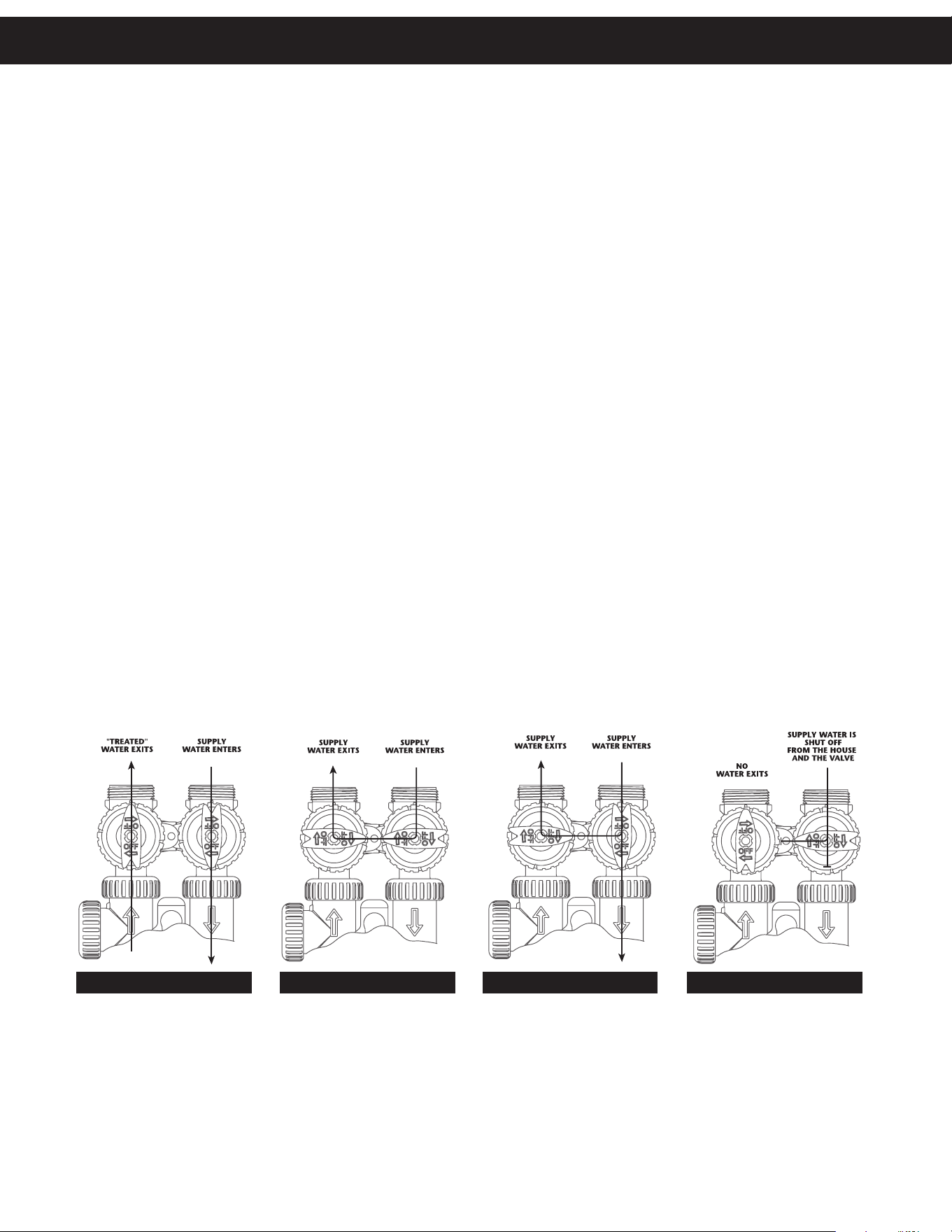
1. NORMAL OPERATION POSITION: The inlet and outlet handles point in the direction of flow indicated by the engraved
arrows on the control valve. Water flows through the control valve for normal operation of a water softener. During
the regeneration cycle this position provides regeneration water to the unit, while also providing untreated water to the
distribution system (Fig. 1).
2. BYPASS POSITION: The inlet and outlet handles point to the center of the bypass. The system is isolated from the water
pressure in the plumbing system. Untreated water is supplied to the building (Fig. 2).
3. DIAGNOSTIC POSITION: The inlet handle points toward the control valve and the outlet handle points to the center of
bypass valve. Untreated supply water is allowed to flow to the system and to the building, while not allowing water to exit
from the system to the building (Fig. 3). This allows the service technician to draw brine and perform other tests without the
test water going to the building.
NOTE: The system must be rinsed before returning the bypass valve to the normal position.
4. SHUT OFF POSITION: The inlet handle points to the center of the bypass valve and the outlet handle points away from
the control valve. The water is shut off to the building. The water treatment system will depressurize upon opening a tap in
the building. A negative pressure in the building combined with the softener being in regeneration could cause a siphoning
of brine into the building. If water is available on the outlet side of the softener, it is an indication of water bypassing the
system (Fig. 4) (i.e. a plumbing cross-connection somewhere in the building).
NORMAL
OPERATION
POSITION
BYPASS POSITION
DIAGNOSTIC
POSITION
SHUT OFF
POSITION
FIGURE 1 FIGURE 3FIGURE 2 FIGURE 4
Bypass Valve
5
Installation
GENERAL INSTALLATION & SERVICE WARNINGS
The control valve, fittings and/or bypass are designed to accommodate minor plumbing misalignments. There is a small
amount of “give” to properly connect the piping, but the water softener is not designed to support the weight of the plumbing.
Do not use Vaseline, oils, other hydrocarbon lubricants or spray silicone anywhere. A silicone lubricant may be used on black
“O” Rings, but is not necessary. Avoid any type of lubricants, including silicone, on red or clear lip seals.
Do not use pipe dope or other sealants on threads. Teflon
®
tape must be used on the threads of the 1” NPT inlet and outlet, the
brine line connection at the control valve, and on the threads for the drain line connection. Teflon
®
tape is not used on the nut
connections or caps because “O” Ring seals are used. The nuts and caps are designed to be unscrewed or tightened by hand
or with the special plastic Service Wrench, #CV3193-02. If necessary pliers can be used to unscrew the nut or cap. Do not
use a pipe wrench to tighten nuts or caps. Do not place screwdriver in slots on caps and/or tap with a hammer.
SITE REQUIREMENTS
• water pressure – 25-100 psi • current draw is 0.5 amperes
• water temperature – 33-100°F (0.5-37.7°C) • the plug-in transformer is for dry locations only
• electrical – 115/120V, 60Hz uninterrupted outlet
• the tank should be on a firm level surface
1. The distance between the drain and the water softener should be as short as possible.
2. Since salt must be periodically added to the brine tank, it should be located where it is easily accessible.
3. Do not install any water softener with less than 10 feet of piping between its outlet and the inlet of a water heater.
4. Do not locate unit where it or its connections (including the drain and overflow lines) will ever be subjected to room
temperatures under 33°F.
5. Do not subject the tank to any vacuum, as this may cause an “implosion” and could result in leaking. If there is a possibility
a vacuum could occur, please make provision for a vacuum breaker in the installation.
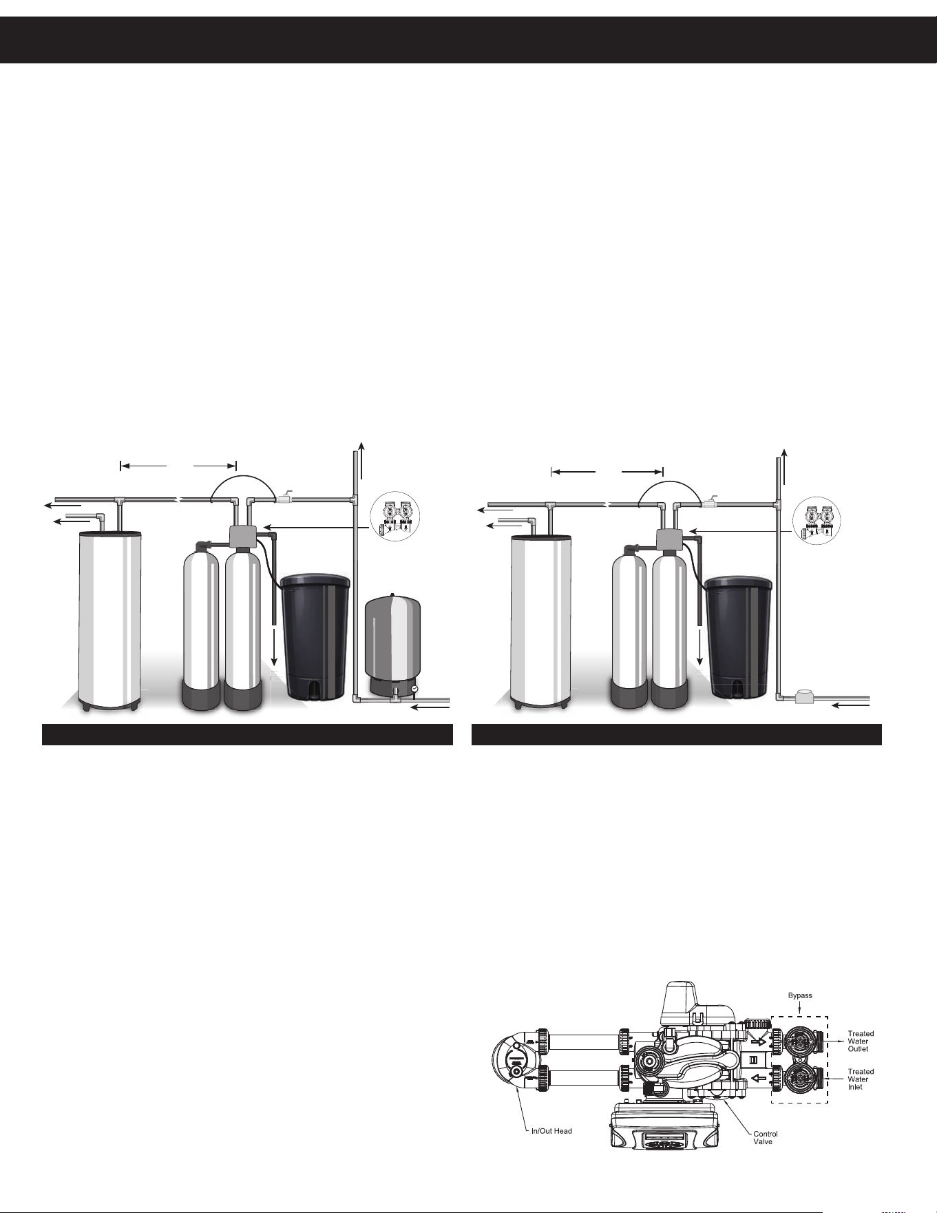
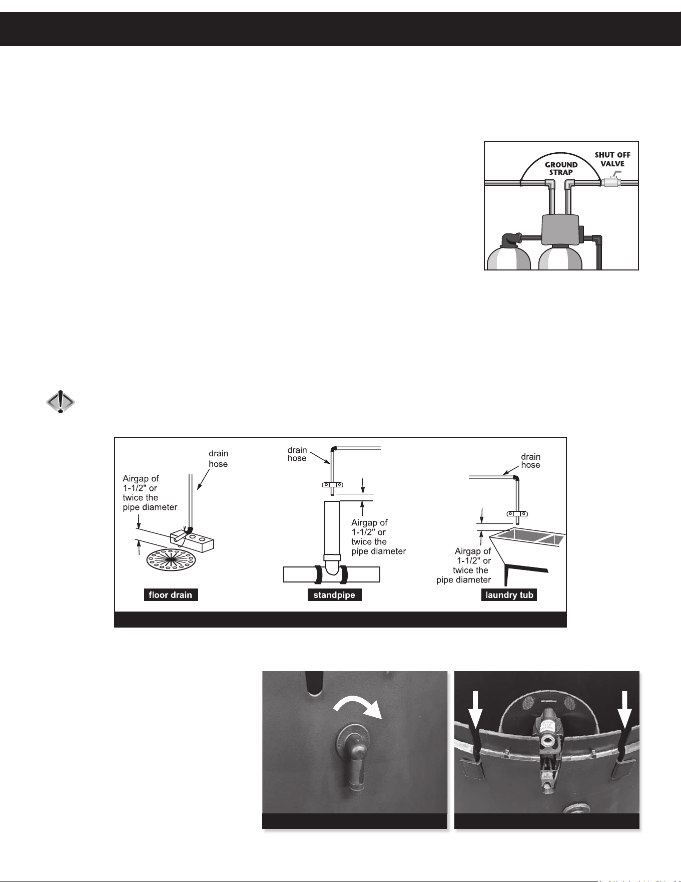
6. INLET/OUTLET PLUMBING: Be sure to install Bypass Valve onto main control
valve before beginning plumbing. (See installation picture to right.
Be sure bypass is connected to treated water inlet
and outlet.) Make provisions to bypass outside hydrant and
cold hard water lines at this time. Install an inlet shutoff valve
and plumb to the unit’s bypass valve inlet located at the right
rear as you face the unit. There are a variety of installation
fittings available. They are listed under Installation Fitting
Assemblies, page 28-30. When assembling the installation
fitting package (inlet and outlet), connect the fitting to the
COLD
HOT
SHUTOFF
VA LV E
GROUND
STRAP
10 FEET
WATER SUPPLY
TO
DRAIN
WATER
HEATER
PRESSURE
TANK
OUTSIDE TA P
O
V
E
R
H
E
A
D
V
I
E
W
O
F
B
Y
P
A
S
S
V
A
L
V
E
OUT
IN
TO
TO
IN
RAIN
R
D
WELL WATER INSTALLATION
COLD
HOT
SHUTOFF
VA LV E
GROUND
STRAP
10 FEET
WATER SUPPLY
TO
DRAIN
WATER
HEATER
WATER
METER
OUTSIDE TA P
O
V
E
R
H
E
A
D
V
I
E
W
O
F
B
Y
P
A
S
S
V
A
L
V
E
OUT
IN
TO
TO
I
N
RAI
N
R
D
MUNICIPAL INSTALLATION
6
Installation
plumbing system first and then attach the nut, split ring and “O” Ring. Heat from soldering or solvent cements may damage the nut,
split ring or “O” Ring. Solder joints should be cool and solvent cements should be set before installing the nut, split ring and “O”
Ring. Avoid getting solder flux, primer, and solvent cement on any part of the “O” Rings, split rings, bypass valve or control valve.
If the building’s electrical system is grounded to the plumbing, install a copper grounding strap from the inlet to the outlet pipe.
Plumbing must be done in accordance with all applicable local codes.
7. INSTALLING GROUND: To maintain an electrical ground in metal plumbing of a home’s
cold water piping (such as a copper plumbing system), install a ground clamp or jumper
wiring. NOTE: If replacing an existing softener, also replace the ground clamps/wire. If
removing a softener, replace the piping with the same type of piping as the original to
assure plumbing integrity and grounding.
8. DRAIN LINE: First, be sure that the drain can handle the backwash rate of the system.
Solder joints near the drain must be done prior to connecting the drain line flow control
fitting. Leave at least 6” between the drain line flow control fitting and solder joints. Failure
to do this could cause interior damage to the flow control. Install a 1/2” I.D. flexible plastic
tube to the Drain Line Assembly or discard the tubing nut and use the 3/4” NPT fitting
for rigid pipe (recommended). If the backwash rate is greater than 7 gpm, use a 3/4” rigid drain line. Where
the drain line is elevated but empties into a drain below the level of the control valve, form a 7” loop at the discharge end
of the line so that the bottom of the loop is level with the drain connection on the control valve. This will provide an adequate
anti-siphon trap. Piping the drain line overhead <10 ft is normally not a problem. Be sure adequate pressure is available (40-
60 psi is recommended). Where the drain empties into an overhead sewer line, a sink-type trap must be used. Run drain tube
to its discharge point in accordance with plumbing codes. Pay special attention to codes for air gaps and anti-siphon devices.
NOTE: Drain line nut will not be supplied for units having a backwash rate greater than 7 gpm.
CAUTION: Never insert a drain line into a drain, sewer line, or trap. Always allow an air gap of 1-1/2” or twice the
pipe diameter, whichever is greater, between the drain line and the wastewater to prevent the possibility of
sewage being back-siphoned into the softener.
bottom drain line
TYPICAL DRAIN LINE INSTALLATIONS
9. BRINE TANK ASSEMBLY: Brine tank components for 19x37” tanks need to be assembled in the field. Follow the steps below:
a. OVERFLOW ELBOW — Screw the
overflow elbow clockwise into the
hole below the brine well slots. The
elbow is self-tapping and does
not require a nut to be secured. Push
against the inside of the tank while
installing the elbow for leverage if
needed (Fig. 5).
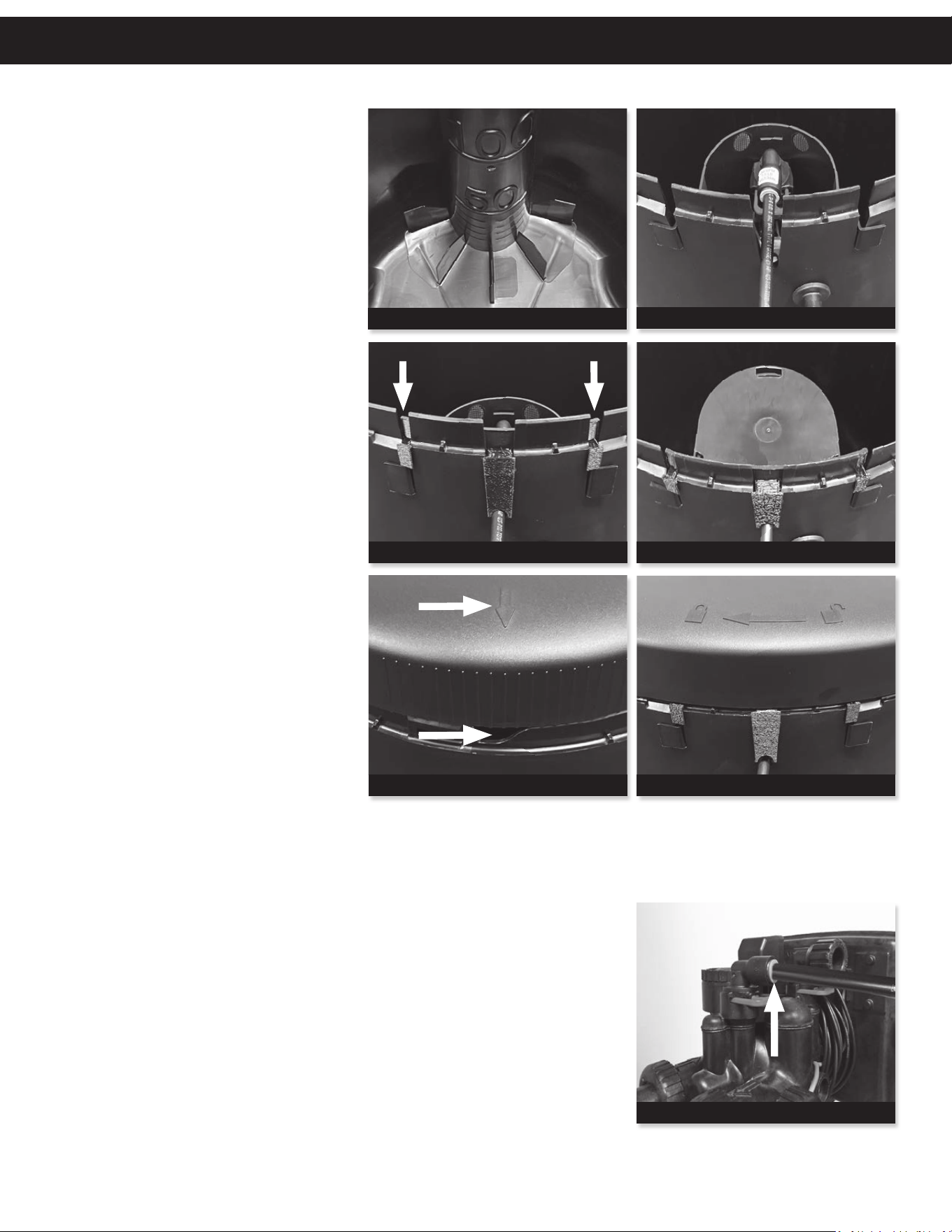
b. BRINE WELL — Install the brine
well by aligning the arms into the
slots on the side of the tank with the
tabs facing outward (Fig. 6).
Continued on next page.
Self-tapping elbow does not require nut.
FIGURE 5
Brine well arms should line up with tank slots.
FIGURE 6
7
Installation Installation
10. OVERFLOW LINE CONNECTION: An
overflow drain line is recommended where a
brine overflow could damage furnishings or
the building structure. Your unit is equipped
with a brine tank safety float which greatly
reduces the chance of an accidental brine
overflow. In the event of a malfunction,
however, an overflow line connection will
direct the “overflow” to the drain instead
of spilling on the floor where it could cause
considerable damage. This fitting is an elbow
on the side of the brine tank, which was
installed in Step 10-a. Finish the setup by attaching a length of 1/2” I.D. tubing to fitting and run to drain. Do not elevate overflow line
higher than 3” below bottom of overflow fitting. Do not connect this tube into the drain line of the control valve. Overflow line must be
a direct, separate line from overflow fitting to drain, sewer, or tub. The overflow line is a gravity drain and cannot run higher than the
initial drain point. Allow an air gap as per the drain line instructions.
11. SAFETY BRINE TANK CONNECTION: Install the 3/8” O.D. polyethylene tube
from the Brine Safety Float valve in the tank to the Refill Elbow on the control valve
(Fig. 13).
12. OVERFLOW LINE CONNECTION: An overflow drain line is recommended where a
brine overflow could damage furnishings or the building structure. Your unit is equipped
with a brine tank safety float which greatly reduces the chance of an accidental brine
overflow. In the event of a malfunction, however, an overflow line connection will
direct the “overflow” to the drain instead of spilling on the floor where it could cause
considerable damage. This fitting is an elbow on the side of the brine tank, which
was installed in Step 10-a. Finish the setup by attaching a length of 1/2” I.D. tubing
to fitting and run to drain. Do not elevate overflow line higher than 3” below bottom
of overflow fitting. Do not connect this tube into the drain line of the control valve.
Overflow line must be a direct, separate line from overflow fitting to drain, sewer, or
tub. The overflow line is a gravity drain and cannot run higher than the initial drain
point. Allow an air gap as per the drain line instructions.
c. BRINE WELL — Ensure the brine well
is properly secured on the bottom of
the tank (Fig. 7).
d. BRINE LINE — Push the brine line
into the flow control elbow of the
safety float assembly until it locks it
into place (Fig. 8).
e. BRINE WELL RETAINER — Install
the brine well retainer above the
brine well by pushing the retainer
down with the tabs facing outward.
Ensure the retainer is flush with the
tank and pushed all the way down
(Fig. 9).
f. BRINE WELL COVER — Snap the
cover over the brine well (Fig. 10).
g. BRINE TANK COVER — Install the
tank cover by aligning the arrows on
the outer edge of the cover with the
indents on the lip of the brine tank
(Fig. 11). Rotate the cover clockwise
1.5” to lock it into place (Fig. 12).
NOTE: The brine tank cover is found
inside the top of the box in the unit
packaging.
Push retainer all the way down onto tank.
FIGURE 9
Push cover onto well to snap into place.
FIGURE 10
Line up arrows on lid with slot on tank.
FIGURE 11
Turn cover clockwise to close securely.
FIGURE 12
Connection at Refill Elbow on the control valve.
FIGURE 13
Bottom of well should be flush against tank.
FIGURE 7
Push brine line all the way in to secure it.
FIGURE 8
8
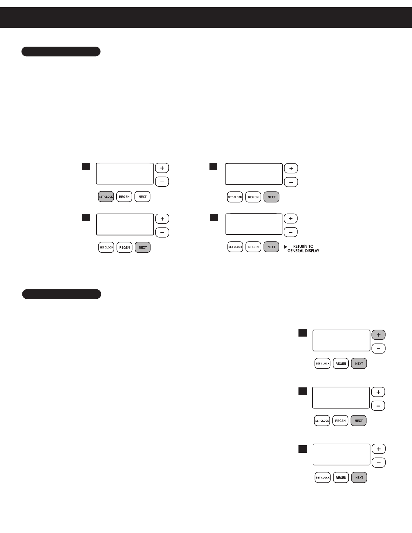
1. Set time of day:
NOTE: The manufacturer has preset the unit so that the gallons between regenerations will be automatically calculated
after the hardness is entered.
STEP 1 – Press next and + simultaneously for 3 seconds.
STEP 2 – HARDNESS: Set the amount of hardness in grains per gallon (default 20)
using the + or — buttons. The allowable range is from 1 to 150 in 1 grain
increments.
NOTE: If a resin media is used in the softener, increase the grains per
gallon if soluble iron is present (1 ppm = 4 gpg). This display will show
“–nA– (not available)” if “FILTER” is selected or if “AUTO” is not factory set.
Press next to go to step 3.
Press regen if you want to exit.
STEP 3 – DAYS BETWEEN REGENERATION (DAY OVERRIDE): The manufacturer
has factory set OFF as the default. When set to “OFF”, regeneration initiation
is based solely on gallons used. If any number is set (allowable range from
1 to 28), a regeneration initiation will be called for on that day even if a
sufficient number of gallons were not used to call for a regeneration.
Set Day Override using + or — buttons (6 is recommended):
• set number of days between regeneration (1 to 28); or
• set to “OFF”
Press next to go to step 4. Press regen to return to the previous step.
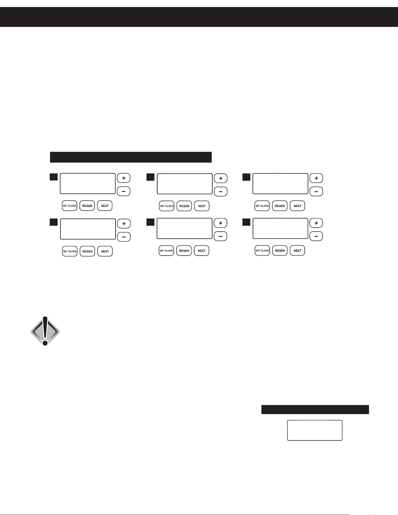
2. Programming:
Time of day should only need to be set after extended power outages or when daylight saving time begins or ends. If an
extended power outage occurs, the time of day will flash on and off indicating that the time should be reset.
STEP 1 – Press set clock.
STEP 2 – CURRENT TIME (HOUR): Set the hour of the day using + or — buttons. AM/PM toggles after 12.
Press next to go to step 3.
STEP 3 – CURRENT TIME (MINUTES): Set the minutes using + or — buttons. If it is desired to back up to the
previous step press regen button once. Press next to go to step 4.
STEP 4 – CURRENT DAY: Set the day of the week using + or — buttons. Pressing next will exit set clock and
return to the general operating display (page 9).
2
3 4
1
1
2
3
TIME HOUR
SET
2:00
AM
TIME MINUTES
SET
2:10
AM
CURRENT DAY
SET
MON
WATER HARDNESS
SET
20
GR
DAYS BETWEEN REGEN
SET
6
Programming Procedures
9
Programming Procedures Programming Procedures
NOTE: The manufacturer has preset the unit so that the gallons between regenerations will be
automatically calculated after the hardness is entered.
STEP 1 – Press next and + simultaneously for 3 seconds.
STEP 2 – HARDNESS: Set the amount of hardness in grains per gallon (default 20)
using the + or — buttons. The allowable range is from 1 to 150 in 1 grain
increments.
NOTE: If a resin media is used in the softener, increase the grains per gallon
if soluble iron is present (1 ppm = 4 gpg). This display will show
“–nA– (not available)” if “FILTER” is selected or if “AUTO” is not factory set.
Press next to go to step 3.
Press regen if you want to exit.
STEP 3 – DAYS BETWEEN REGENERATION (DAY OVERRIDE): The manufacturer
has factory set OFF
as the default. When set to “OFF”, regeneration initiation is
based solely on gallons used. If any number is set (allowable range from 1 to
28), a regeneration initiation will be called for on that day even if a sufficient
number of gallons were not used to call for a regeneration.
Set Day Override using + or — buttons (6 is recommended):
• set number of days between regeneration (1 to 28); or
• set to “OFF”
Press next to go to step 4. Press regen to return to the previous step.
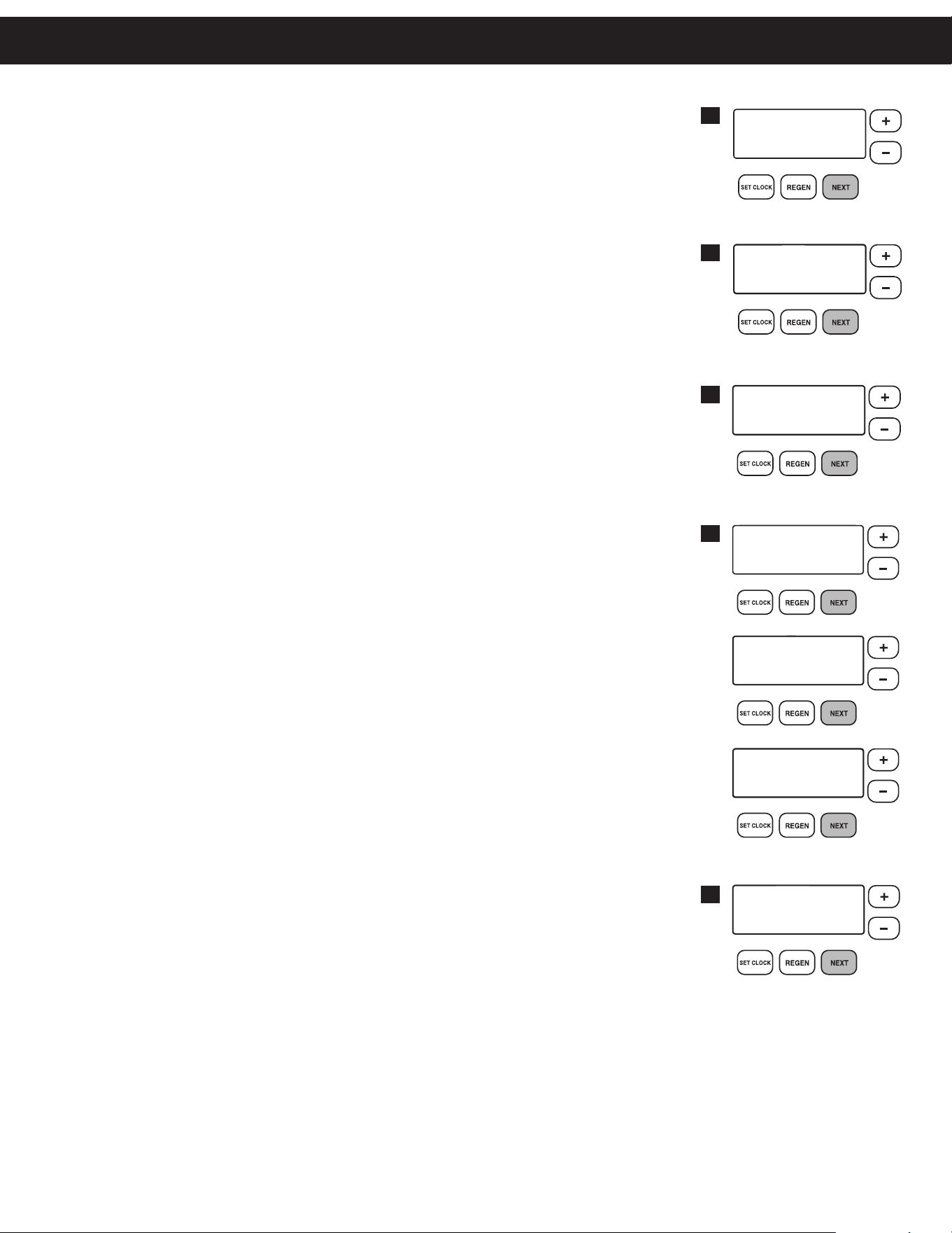
STEP 4 – IMMEDIATE REGENERATION: The manufacturer has set the regeneration to
occur when zero gallons remain. When this occurs, the standby tank will switch
into service and provide treated water while the tank requiring regeneration will
start this process.
Press next to go to step 5. Press regen to return to the previous step.
STEP 5 – SERVICE ALARM GALLONS: The manufacturer has factory set “OFF”
as the default. This feature is used to signal service into the future. This is
typically set by the installing dealer to warn homeowner that service is
required after a preset number of gallons have been consumed. If the
feature is active, a specific gallon amount will appear.
Press next three times to advance past this screen.
STEP 6 – SERVICE ALARM TIME: The manufacturer has factory set “OFF” as the
default. This feature is used to signal service into the future. This is typically
set by the installing dealer to warn homeowner that service is required after a
period of time has passed. If the feature is active, a specific number of days
4
5
ALARM BUZZER START
SET
ALARM BUZZER END
SET
6:00
AM
ALARM BUZZER
SET
ON
10:00
PM
7
8
6
SERVICE ALARM
SET
OFF
SERVICE ALARM GAL
SET
100
GAL
GAL
REGEN IMMEDIATE
ON ZERO
SERVICE ALARM
SET
OFF
SERVICE ALARM TIME
SET
1.25
YR
LIGHT NORMALLY
SET
ON
10
1. GENERAL OPERATION: When the system is operating, one of five displays may be shown and will alternate with the
installing dealer’s name and phone number (if set) for future service. Pressing next will alternate between the displays.
1. CURRENT TIME OF DAY and GPM. Letter indicates which tank is in service. GPM alternates with current flow rate.
2. FLOW RATE which is the current treated water flow rate through either tank A or B in Gallons Per Minute.
3. VACATION MODE allows the system to be “shut down” when there will be no water usage for an extended
period of time.
4. CAPACITY REMAINING for the tank in service (A or B) and the gallons that will be treated before the system
signals a regeneration cycle and switches to the other tank. GPM alternates with current flow rate.
5. DAYS TO A REGEN is the number of days left before the system goes through a regeneration cycle, based on the
days override value. Letter indicates which tank is in service. GPM alternates with current flow rate.
6. DEALER NAME AND PHONE NUMBER is the dealer information to call when service is needed (this screen will
only appear if set by dealer).
The user can scroll between the displays as desired.
2. VACATION MODE: This feature may be used to “shut down” the system while on vacation. The manufacturer has
factory set “OFF” as the default. Turn feature “OFF” or “ON” using the + or — buttons. When turned “ON”, the
unit will not regenerate while there is no water usage. Once water usage is observed (minimum of 50 gallons), the
unit will automatically regenerate that night and resume normal operation.
CAUTION: Depending on the severity of water conditions and the length of no water
usage, it may not be recommended to use this feature. Please contact
dealer or manufacturer for more information.
3. MANUAL REGENERATION: Sometimes there is a need to regenerate before the control valve calls for it. This
may be needed if the system has been operated without salt for an extended period of time. To initiate a manual
regeneration immediately, press and hold the regen button for three seconds. The system will begin to regenerate
immediately. This command cannot be cancelled.
Once a manual regeneration is initiated, the unit will transfer to the second tank in order to supply conditioned
water. Upon transfer, the depleted tank will begin its regeneration.
4. REGENERATION MODE: Typically a twin system regenerates when the capacity
of the tank providing treated water reaches zero remaining gallons. At this time, the
online tank will transfer and put the standby tank online so there is no disruption
of treated water. Once this transfer is complete, the depleted tank will regenerate
and return to standby mode ready to enter service upon depletion of capacity of
other tank. This two tank configuration provides for a continuous, uninterrupted
supply of conditioned water at all times. When the system begins to regenerate, the display will change to include
information about the step of the regeneration process and the time remaining for that step to be completed.
The system will run through all remaining steps automatically and will reset to provide treated water when the
regeneration process has been completed.
BACKWASH
8:22
REGENERATION MODE
1
TIME OF DAY MON
GPM
2:40A
PM
2
FLOW RATE
GPM
8.0A
5
DAYS TO A REGEN
GPM
3
A
6
PHONE NUMBER
DEALER NA
3
ON VACATION
NO
4
CAPACITY REMAINING
GPM GAL
1600
A
Operating Displays & Maintenance
11
Operating Displays & Maintenance
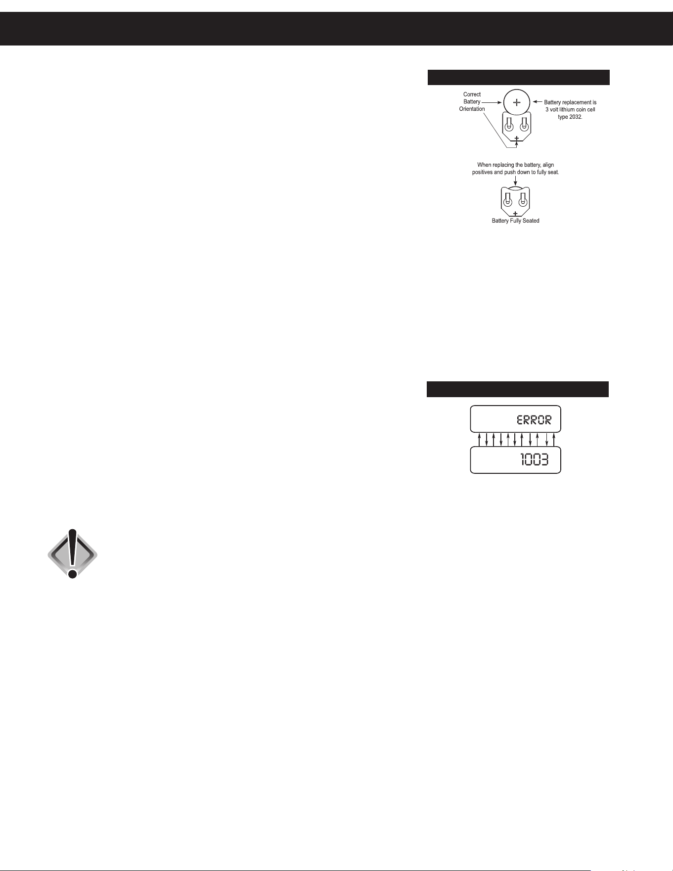
5. POWER LOSS AND BATTERY REPLACEMENT: The transformer comes with a
15 foot power cord and is designed for use with the control valve; the transformer
should only be used in a dry location.
In the event of a power outage, the control valve will remember all settings and
time of day. If an extended power outage occurs, the control valve will keep time
of day until the battery is depleted. When the battery becomes depleted, the only
item that needs to be reset is the time of day and will be indicated by the time of
day flashing. All other settings are permanently stored in the nonvolatile memory.
If a power loss occurs and the time of day flashes, this indicates that the battery
is depleted. The time of day should be reset and the non-rechargeable battery
should be replaced. The battery is a 3 Volt Lithium Coin Cell type 2032 and is
readily available at most stores. To access battery location, remove front cover
(see diagram on page 18 for battery location).
6. CHECK SALT INDICATOR AND AUDIBLE ALARM (OPTIONAL): This control valve may be equipped with a Low
Salt Warning to alert homeowners that the system is operating in a low salt condition. This usually indicates that the salt
level in the brine tank is too low to operate properly. If “CHECK SALT” appears, there will usually be an audible alarm
that sounds also (if turned on), alerting you to these conditions.
To turn off alarm: If the audible alarm sounds due to a low salt condition, press any button on the face of the
control valve to turn off. If salt is not added to the brine tank before the next regeneration,
the CHECK SALT indicator will alarm again.
IMPORTANT: If you feel that the salt level is adequate (at least 1/3 full) in the brine tank, please contact the dealer
that installed your system for service.
7. ERROR MESSAGE: If the word “ERROR” appears and flashes alternately with
the dealer name and phone number, record the ERROR number and your contact
servicing dealer promptly. This indicates that the control valve was not able to
function properly.
8. BRINE TANK MAINTENANCE AND SALT: Refill the brine tank as necessary,
making sure at least 1/3 of the brine tank is full at all times. Without proper salt
levels, the water softener may not operate properly.
The manufacturer recommends the use of solar salt for best results. The brine tank is manufactured for the use of
solar, pellets or rock salt. If pellet or rock salt is used, a cleaning of the brine tank every six months is recommended.
CAUTION: With some models the manufacturer does NOT recommend the use of
any resin cleaners, nor placing any resin cleaners into the brine tank.
Furthermore, do not use any salt that indicates it is an iron cleaning salt
or that contains any cleaning additives. This may be harmful to the water
softener and for human consumption. Consult dealer for proper cleaning
instructions and agents.
BATTERY REPLACEMENT
ERROR

12
FLUSHING OF SYSTEM:
To flush the system of any debris and air after installation is complete, please perform the following steps:
1. Rotate bypass handles to the bypass mode (see Fig. 2 of page 4).
2. Turn on inlet water and check for leaks in the newly installed plumbing.
3. Fully open a cold water faucet, preferable at a laundry sink or bathtub without an aerator.
4. Allow water to run until clear to rid pipes of debris which may have occurred during installation.
System regeneration sequence is in the following order. (If it is desired to change this sequence, please refer to the Dealer
Master Programming Guide or contact the manufacturer.)
1) BACKWASH 4) BRINE TANK FILL
2) BRINE and RINSE DOWN 5) END (returns to Standby)
3) RAPID RINSE The system is now ready for filling with water and for testing.
1. With the softener in the bypass mode (Fig. 2 on page 4) and the control valve in normal operation where the display
shows either the time of day or the gallons remaining, manually add 8” of water to the regenerant tank.
NOTE: If too much water is put into the brine tank during softener start up, it could result in a “salty water” complaint after
the first regeneration.
During the first regeneration the unit will draw out the initial volume of brine/regenerant and refill it with the correct preset amount.
2. With the softener in bypass mode, press and hold the regen button until the motor starts. Release button. The display will read
“Pend 0” for about three seconds while the system transfers from one tank to another. After the transfer is complete, the valve will
automatically advance to the “Backwash” position. Once the valve has stopped in this position, unplug the transformer so that
the valve will not cycle to the next position. Open the inlet handle of the bypass valve very slightly, allowing water to fill the tank
slowly in order to expel air from the tank.
CAUTION: If water flows too rapidly, there will be a loss of media to the drain.
3. When the water is flowing steadily to the drain, clear and without the presence of air, slowly open the inlet valve. Restore
power and momentarily press the regen button to advance the control to the “BRINE” position.
4. With the bypass now in diagnostic mode (Fig. 3 on page 4), check to verify that water is being drawn from regenerant tank
with no air leaks or bubbles in the brine line. There should be a slow flow to the drain. Disconnect brine line from the safety float
valve in the brine tank and check for a vacuum. After proper confirmation, reconnect brine line, making sure to tighten securely.
5. Momentarily press regen again until the display reads “RINSE.” There should be a rapid flow to the drain. Unplug transformer
to keep the valve in the “RINSE” position. Allow to run until steady, clear and without air. While the unit is rinsing, load the
brine tank with water softener salt (refer to page 10, Brine Tank Maintenance and Salt). Restore power.
6. Push regen again and the unit will advance to the “Brine Refill” position. Check to make sure the brine tank is refilling.
The flow rate is usually .5 gpm for all residential and light commercial applications.
7. Push next and the unit will return to normal operation.
8. Place unit into bypass mode again (see Fig. 2 on page 4) and press and hold the regen button to allow control valve to
transfer to the second tank. Follow steps 2-7 to now expel air from this tank.
9. When finished expelling air from second tank, return bypass handles to normal operating position (see Fig. 1 on page 4).
The unit is now online and soft water is available for use.
10. CONDITIONING OF MEDIA (To flush any remaining debris and air from the system):
1. Fully open a cold water faucet, preferably at a laundry sink or bathtub without an aerator.
2. Wait two to three minutes or until water runs clear, then turn water off.
3. Turn on hot water and check for air, then turn water off after air is discharged.
11. SANITIZING OF UNIT UPON INSTALLATION AND AFTER SERVICE (At this time, it is advised to sanitize the softener):
1. Open brine tank and remove brine well cover.
2. Pour 1 oz. of household bleach into the softener brine well.
3. Replace brine well cover.
NOTE: Avoid pouring bleach directly onto the safety float components in the brine well.
Unit sanitizing will be complete when the first cycle is run and the bleach is flushed from the softener.
12. Check time of day. Start-up is now complete.
Start-Up Instructions

13
This page intentionally left blank.
14
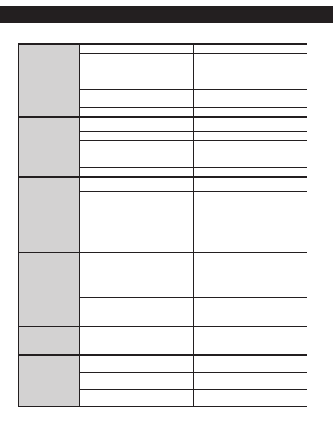
PROBLEM CAUSE CORRECTION
1. No display on
PC board
A. No power at electric outlet A. Repair outlet or use working outlet
B. Control valve power adapter not plugged into
outlet or power cord end not connected to PC
board connection
B. Plug power adapter into outlet or connect
power cord end to PC board connection
C. Improper power supply
C. Verify proper voltage is being delivered to
PC board
D. Defective power adapter D. Replace power adapter
E. Defective PC board E. Replace PC board
F. Dead battery F. Replace battery
2. PC board does not
display correct time
of day
A. Power adapter plugged into electric outlet
controlled by light switch
A. Use uninterrupted outlet
B. Tripped breaker switch and/or tripped GFI B. Reset breaker switch and/or GFI switch
C. Power outage
C. Reset time of day. If PC board has battery
back up present the battery may be depleted.
See front cover and drive assembly drawing
for instructions.
D. Defective PC board D. Replace PC board
3. Display does not
indicate that water is
flowing. Refer to user
instructions for how the
display indicates water
is flowing.
A. Bypass valve in bypass position
A. Turn bypass handles to place bypass in
service position
B. Meter is not connected to meter connection on
PC board
B. Connect meter to three pin connection labeled
METER on PC board
C. Restricted/stalled meter turbine
C. Remove meter and check for rotation or
foreign material
D. Meter wire not installed securely into three
pin connector
D. Verify meter cable wires are installed securely
into three pin connector labeled METER
E. Defective meter E. Replace meter
F. Defective PC board F. Replace PC board
4. Control valve
regenerates at wrong
time of day
A. Power outage
A. Reset time of day. If PC board has battery
back up present the battery may be depleted.
See front cover and drive assembly drawing
for instructions.
B. Time of day not set correctly B. Reset to correct time of day
C. Time of regeneration set incorrectly C. Reset regeneration time
D. Control valve set at “on 0” (immediate
regeneration)
D. Check programming setting and reset to
NORMAL (for a delayed regen time)
E. Control valve set at “NORMAL + on 0”
(delayed and/or immediate)
E. Check programming setting and reset to
NORMAL (for a delayed regen time)
5. Time of day flashes on
and off
A. Power outage
A. Reset time of day. If PC board has battery
back up present the battery may be depleted.
See diagram on page 18 for battery location.
6. Control valve does not
regenerate automatically
when the correct button(s)
is depressed and held.
A. Broken drive gear or drive cap assembly A. Replace drive gear or drive cap assembly
B. Broken piston rod B. Replace piston rod
C. Defective PC board C. Defective PC board
Troubleshooting Guide
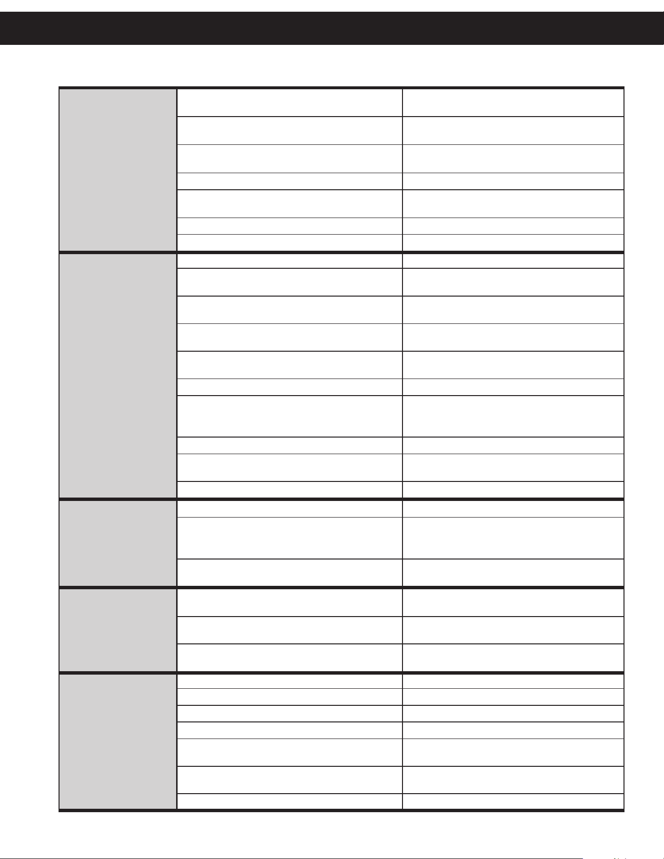
15
7. Control valve does not
regenerate automatically
but does when the
correct button(s) is
depressed and held.
A. Bypass valve in bypass position
A. Turn bypass handles to place bypass in
service position
B. Meter is not connected to meter connection on
PC board
B. Connect meter to three pin connection labeled
METER on PC board
C. Restricted/stalled meter turbine
C. Remove meter and check for rotation or
foreign material
D. Incorrect programming D. Check for programming error
E. Meter wire not installed securely into three
pin connector
E. Verify meter cable wires are installed securely
into three pin connector labeled METER
F. Defective meter F. Replace meter
G. Defective PC board G. Replace PC board
8. Hard or untreated
water is being
delivered
A. Bypass valve is open or faulty A. Fully close bypass valve or replace
B. Media is exhausted due to high water usage
B. Check program settings or diagnostics for
abnormal water usage
C. Meter not registering
C. Remove meter and check for rotation or
foreign material
D. Water quality fluctuation
D. Test water and adjust program
values accordingly
E. No regenerant or low level of regenerant in
regenerant tank
E. Add proper regenerant to tank
F. Control fails to draw in regenerant F. Refer to Troubleshooting Guide number 12
G. Insufficient regenerant level in regenerant tank
G. Check refill setting in programming. Check
refill flow control for restrictions or debris and
clean or replace
H. Damaged seal/stack assembly H. Replace seal/stack assembly
I. Control valve body type and piston type
mix matched
I. Verify proper control valve body type and
piston type match
J. Fouled media bed J. Replace media bed
9. Control valve uses too
much regenerant
A. Improper refill setting A. Check refill setting
B. Improper program settings
B. Check program setting to make sure
they are specific to the water quality and
application needs
C. Control valve regenerates frequently
C. Check for leaking fixtures that may be
exhausting capacity or system is undersized
10. Residual regenerant
being delivered to
service
A. Low water pressure
A. Check incoming water pressure – water
pressure must remain at minimum of 25 psi
B. Incorrect injector size
B. Replace injector with correct size for
the application
C. Restricted drain line
C. Check drain line for restrictions or debris
and clean
11. Excessive water in
regenerant tank
A. Improper program settings A. Check refill setting
B. Plugged injector B. Remove injector and clean or replace
C. Drive cap assembly not tightened in properly C. Retighten the drive cap assembly
D. Damaged seal/stack assembly D. Replace seal/stack
E. Restricted or kinked drain line
E. Check drain line for restrictions or debris and
or unkink drain line
F. Plugged backwash flow controller
F. Remove backwash flow controller and clean
or replace
G. Missing refill flow controller G. Replace refill flow controller
PROBLEM CAUSE CORRECTION
Troubleshooting Guide
16
12. Control valve fails to
draw in regenerant
A. Injector is plugged A. Remove injector and clean or replace
B. Faulty regenerant piston B. Replace regenerant piston
C. Regenerant line connection leak C. Inspect regenerant line for air leak
D. Drain line restriction or debris cause excess
back pressure
D. Inspect drain line and clean to
correct restriction
E. Drain line too long or too high E. Shorten length and or height
F. Low water pressure
F. Check incoming water pressure – water
pressure must remain at minimum of 25 psi
13. Water running to
drain
A. Power outage during regeneration
A. Upon power being restored control will finish
the remaining regeneration time. Reset time of
day. If PC board has battery back up present
the battery may be depleted. See front cover
and drive assembly drawing for instructions.
B. Damaged seal/stack assembly B. Replace seal/stack assembly
C. Piston assembly failure C. Replace piston assembly
D. Drive cap assembly not tightened in properly D. Retighten the drive cap assembly
14. E1, Err – 1001,
Err – 101 =
Control unable
to sense motor
movement
A. Motor not inserted fully to engage pinion,
motor wires broken or disconnected
A. Disconnect power, make sure motor is fully
engaged, check for broken wires, make sure
two pin connector on motor is connected to the
two pin connection on the PC board labeled
MOTOR. Press NEXT and REGEN buttons for
3 seconds to resynchronize software with piston
position or disconnect power supply from PC
board for 5 seconds and then reconnect.
B. PC board not properly snapped into drive bracket
B. Properly snap PC board into drive bracket and
then Press NEXT and REGEN buttons for 3
seconds to resynchronize software with piston
position or disconnect power supply from PC
board for 5 seconds and then reconnect.
C. Missing reduction gears C. Replace missing gears
15. E2, Err – 1002, Err –
102 = Control valve
motor ran too short
and was unable to
find the next cycle
position and stalled
A. Foreign material is lodged in control valve
A. Open up control valve and pull out piston
assembly and seal/stack assembly for
inspection. Press NEXT and REGEN buttons for
3 seconds to resynchronize software with piston
position or disconnect power supply from PC
board for 5 seconds and then reconnect.
B. Mechanical binding
B. Check piston and seal/stack assembly, check
reduction gears, check drive bracket and main
drive gear interface. Press NEXT and REGEN
buttons for 3 seconds to resynchronize software
with piston position or disconnect power supply
from PC board for 5 seconds and then reconnect.
C. Main drive gear too tight
C. Loosen main drive gear. Press NEXT and
REGEN buttons for 3 seconds to resynchronize
software with piston position or disconnect
power supply from PC board for 5 seconds
and then reconnect.
D. Improper voltage being delivered to PC board
D. Verify that proper voltage is being supplied.
Press NEXT and REGEN buttons for 3 seconds
to resynchronize software with piston position
or disconnect power supply from PC board for
5 seconds and then reconnect.
PROBLEM CAUSE CORRECTION
Troubleshooting Guide

17
PROBLEM CAUSE CORRECTION
16. E3, Err – 1003, Err –
103 = Control valve
motor ran too long
and was unable to find
the next cycle position
A. Motor failure during a regeneration
A. Check motor connections then Press NEXT and
REGEN buttons for 3 seconds to resynchronize
software with piston position or disconnect
power supply from PC board for 5 seconds
and then reconnect.
B. Foreign matter built up on piston and stack
assemblies creating friction and drag enough
to time out motor
B. Replace piston and stack assemblies. Press
NEXT and REGEN buttons for 3 seconds to
resynchronize software with piston position
or disconnect power supply from PC board
for 5 seconds and then reconnect.
C. Drive bracket not snapped in properly and out
enough that reduction gears and drive gear do
not interface
C. Snap drive bracket in properly then Press
NEXT and REGEN buttons for 3 seconds to
resynchronize software with piston position
or disconnect power supply from PC board
for 5 seconds and then reconnect.
17. E4, Err – 1004, Err –
104 = Control valve
motor ran too long
and timed out trying
to reach home position
A. Drive bracket not snapped in properly and out
enough that reduction gears and drive gear do
not interface
A. Snap drive bracket in properly then Press
NEXT and REGEN buttons for 3 seconds to
resynchronize software with piston position
or disconnect power supply from PC board
for 5 seconds and then reconnect.
18. Err -1006, Err – 106,
Err - 116 = MAV/
SEPS/ NHBP/ AUX
MAV valve motor ran
too long and unable
to find the proper
park position
Motorized Alternating
Valve = MAV
Separate Source = SEPS
No Hard Water Bypass
= NHBP
Auxiliary MAV = AUX
MAV
A. Control valve programmed for ALT A or B,
nHbP, SEPS, or AUX MAV with out having
a MAV or NHBP valve attached to operate
that function
A. Press NEXT and REGEN buttons for 3 seconds
to resynchronize software with piston position
or disconnect power supply from PC board for
5 seconds and then reconnect. Then reprogram
valve to proper setting
B. MAV/NHBP motor wire not connected to
PC board
B. Connect MAV/NHBP motor to PC board two
pin connection labeled DRIVE. Press NEXT and
REGEN buttons for 3 seconds to resynchronize
software with piston position or disconnect
power supply from PC board for 5 seconds
and then reconnect.
C. MAV/NHBP motor not fully engaged with
reduction gears
C. Properly insert motor into casing, do not force
into casing Press NEXT and REGEN buttons for
3 seconds to resynchronize software with piston
position or disconnect power supply from PC
board for 5 seconds and then reconnect.
D. Foreign matter built up on piston and stack
assemblies creating friction and drag enough
to time out motor
D. Replace piston and stack assemblies. Press
NEXT and REGEN buttons for 3 seconds to
resynchronize software with piston position
or disconnect power supply from PC board
for 5 seconds and then reconnect.
19. Err – 1007, Err – 107,
Err - 117 = MAV/
SEPS/NHBP/AUX
MAV valve motor
ran too short (stalled)
while looking for
proper park position
Motorized Alternating
Valve = MAV
Separate Source = SEPS
No Hard Water Bypass
= NHBP
Auxiliary MAV = AUX
MAV
A. Foreign material is lodged in
MAV/NHBP valve
A. Open up MAV/NHBP valve and check piston
and seal/ stack assembly for foreign material.
Press NEXT and REGEN buttons for 3 seconds
to resynchronize software with piston position
or disconnect power supply from PC board for
5 seconds and then reconnect.
B. Mechanical binding
B. Check piston and seal/stack assembly, check
reduction gears, drive gear interface, and c
heck MAV/NHBP black drive pinion on motor
for being jammed into motor body. Press
NEXT and REGEN buttons for 3 seconds to
resynchronize software with piston position or
disconnect power supply from PC board for 5
seconds and then reconnect.
Troubleshooting Guide
18
Release locking tabs
from each side to
remove back plate.
TRANSFER CAP ASSEMBLIES SERVICE INSTRUCTIONS
1. The backplate of the control valve must
first be removed to allow access to the
transfer cap assembly.
2. Hold slight downward pressure on the
top left corner of the backplate while
using a thin flat screwdriver or knife
blade to push in on the locking tabs.
This will release the backplate and it
will twist to the left of the valve body.
3. For removal of the drive motor side
(Fig. 3), remove the drive cover
assembly to access the motorized drive.
The drive motor can be removed by
pressing the spring clip loop to the right
then rotating the motor a quarter turn.
Pull outward to remove the motor from
the reducing gear cover assembly.
4. Remove the three Phillips head stainless
steel screws that retain the reducing
gear cover to the drive cap.
5. Once the cover is removed, there will be access to the reducing drive gears. Simply slide them off of the gear axles, then
inspect and check them (there are three small black gears with foil decals and one larger black reducing gear).
6. Remove the large white drive gear from the stainless steel drive shaft. To remove the large white transfer drive gear, firmly
grab the outside edge of the gear and pull it outward away from the control valve assembly.
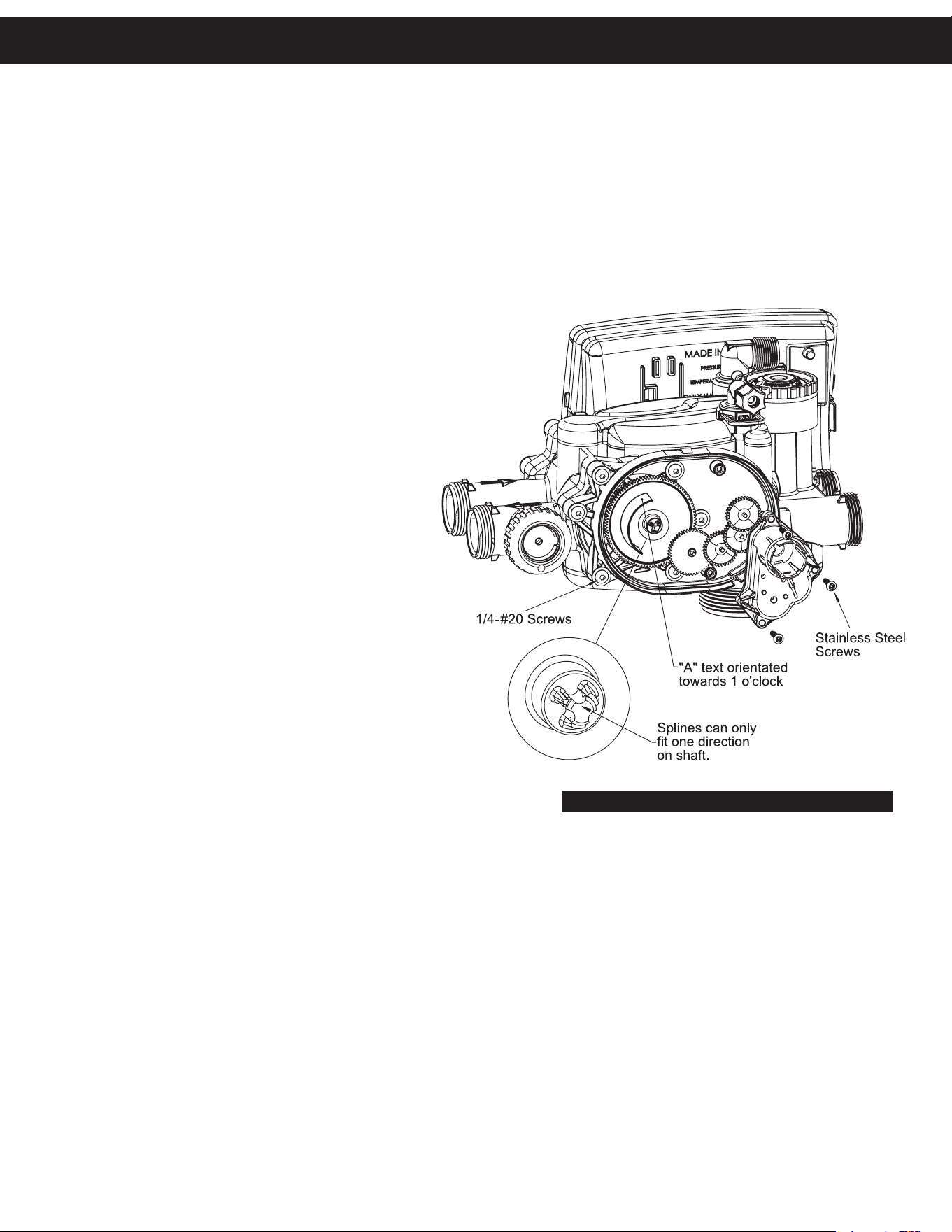
7. Use a 5/32" or 4mm allen wrench to remove the ¼-#20 screws (six screws on each side) that retain the transfer drive cap
assemblies on both sides of the valve.
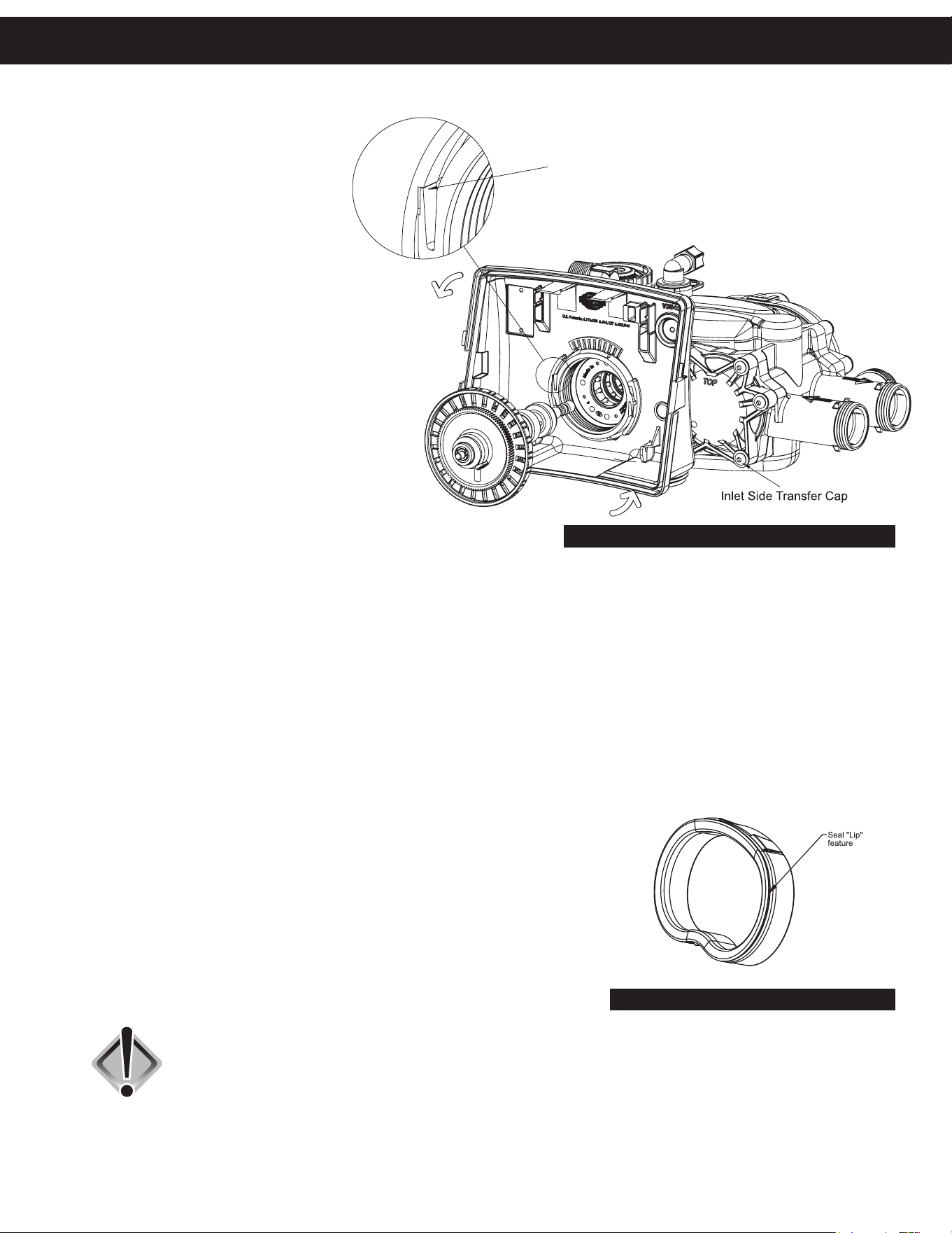
8. Once the screws are removed from retaining the inlet side transfer valve cap and the outlet drive motor transfer cap from the
control valve, the cap will spring out away from the valve body. At this point the transfer discs may be removed by pulling
the discs outward off of the shaft away from the valve body. With the disc out, inspect the flat surface area to be sure it is
clean, smooth and free of any debris or scratches. Note that the disc is keyed to the drive shaft so that it will only assemble
in one orientation. (See parts diagram on page 20.)
9. The transfer discs may be chemically cleaned with a dilute sodium bisulfate
solution (Iron Out), vinegar or just wiped with a soft clean cloth.
10. To remove seals, gently pull out on the outer lip of the seal to lift the seal out from
its cavity being careful not to damage the face surface of the seal.
11. To reassemble, reseat seals into the seal cavity of the control valve body being
sure that the lip of the seal is facing outward. See Fig. 2.
12. With seals in place, put a thin film of Dow #7 silicone grease on the tops of
the seals and the flat surface of the discs.
CAUTION: Do not use Vaseline, petroleum jelly or any other hydrocarbon lubricants on
plastic components or O-rings as they will cause damage to the material and
can potentially cause leaks in the system.
13. Prior to reinstalling the discs, the drive shaft should be removed and the O-rings cleaned, inspected and lubricated with
Dow #7 silicone grease. The shaft can now be installed into the disc prior to installation.
FIGURE 1
FIGURE 2
Transfer Cap Assembly Service
19
14. With the outlet disc assembled to the shaft, the orientation of the shaft to inlet disc can be assured by installing the set
with the through hole on the outlet disc at the 6 o’clock position. The easiest way to reassemble is to remove both disc
drives and assemble the outlet side first. Then each disc can be fitted on the shaft individually. At this point the transfer
valve cap assemblies can be reinstalled.
NOTE: Both transfer caps only mount in one orientation. Prior to installation of cap assembly, be sure to check that the
stainless steel spring and the plastic spring support is in place and attached to the inside of the assembly.
15. Wipe the outside edge of the O-ring on the cap and the inside mating area of the valve with a clean cloth and reapply
a thin layer of Dow #7 silicone grease.
16. Noting the one possible orientation of the transfer drive cap, use
one hand to press in and support the transfer drive cap while
using the opposing hand to start two screws in, one on the top
and one opposing it on the bottom. Tighten the screws evenly
so that the cap seats the O-ring without getting pinched or
damaged. Screws should only be hand tightened with a 5/32”
or 4mm allen wrench. DO NOT OVER TIGHTEN SCREWS.
NOTE: Take care to be certain the meter cable doesn’t
get under the drive cap while tightening as it will result in
damaging the cable.
17. Position the large white drive gear with the “A”
pointing toward the one o’clock position and
then press it onto the stainless steel drive shaft,
making sure it snaps and locks into position.
NOTE: The white drive gear is splined to the drive
shaft and will only assemble in one orientation.
Because of this, it is not necessary that the discs and
gear be exactly positioned. The positioning needs to
be approximate but they have to fit on the shaft.
18. Install the larger black reducing gear onto the stainless
steel shaft, then install the remaining smaller reducing
gears from left to right.
19. Reinstall the grey reducing gear cover over the gears and
affix with the three stainless steel screws.
20. Reinstall the drive motor by pressing the spring clip loop to the
right, then rotate the motor as you are inserting it so the gear
of the motor meshes properly with the reducing gears.
21. Release the spring clip loop and rotate the motor until the motor housing engages with the plastic nub inside the housing
that holds the motor in place, making sure that the top of the motor is flush with the top of the grey gear housing.
22. Press the drive motor wires down into the strain relief of the drive cap.
23. Reinstall the cover assembly.
After completing any valve maintenance involving the valve drive assembly or the transfer drive assembly, press and hold
the next and regen buttons simultaneously for three to five seconds to perform a soft reset which will synchronize the control
valves positions.
FIGURE 3
Transfer Cap Assembly Service
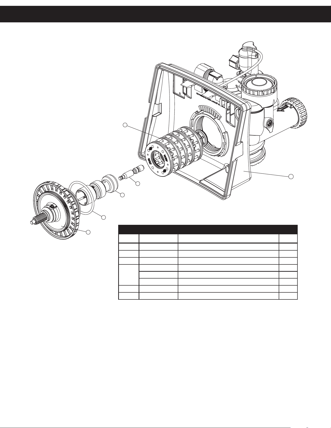
20
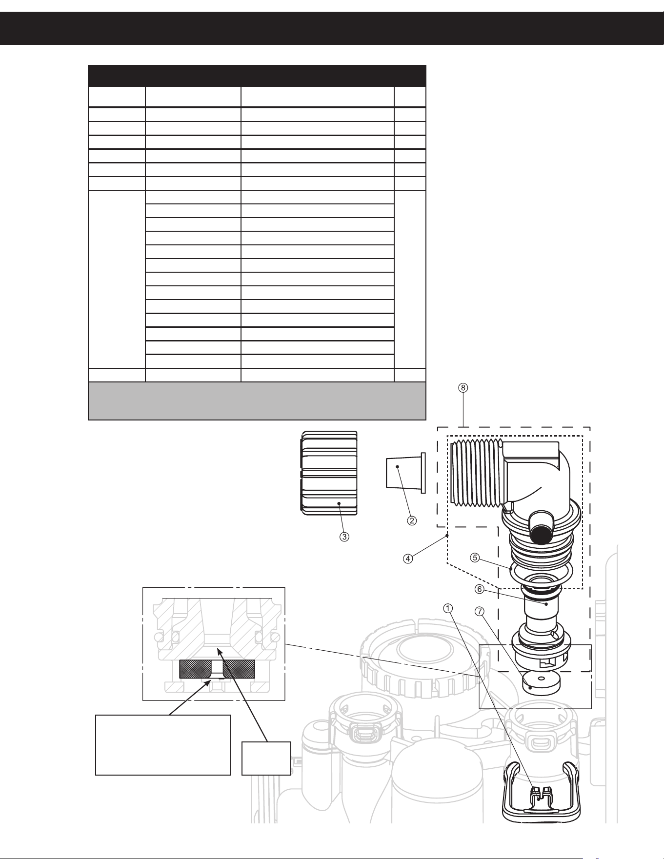
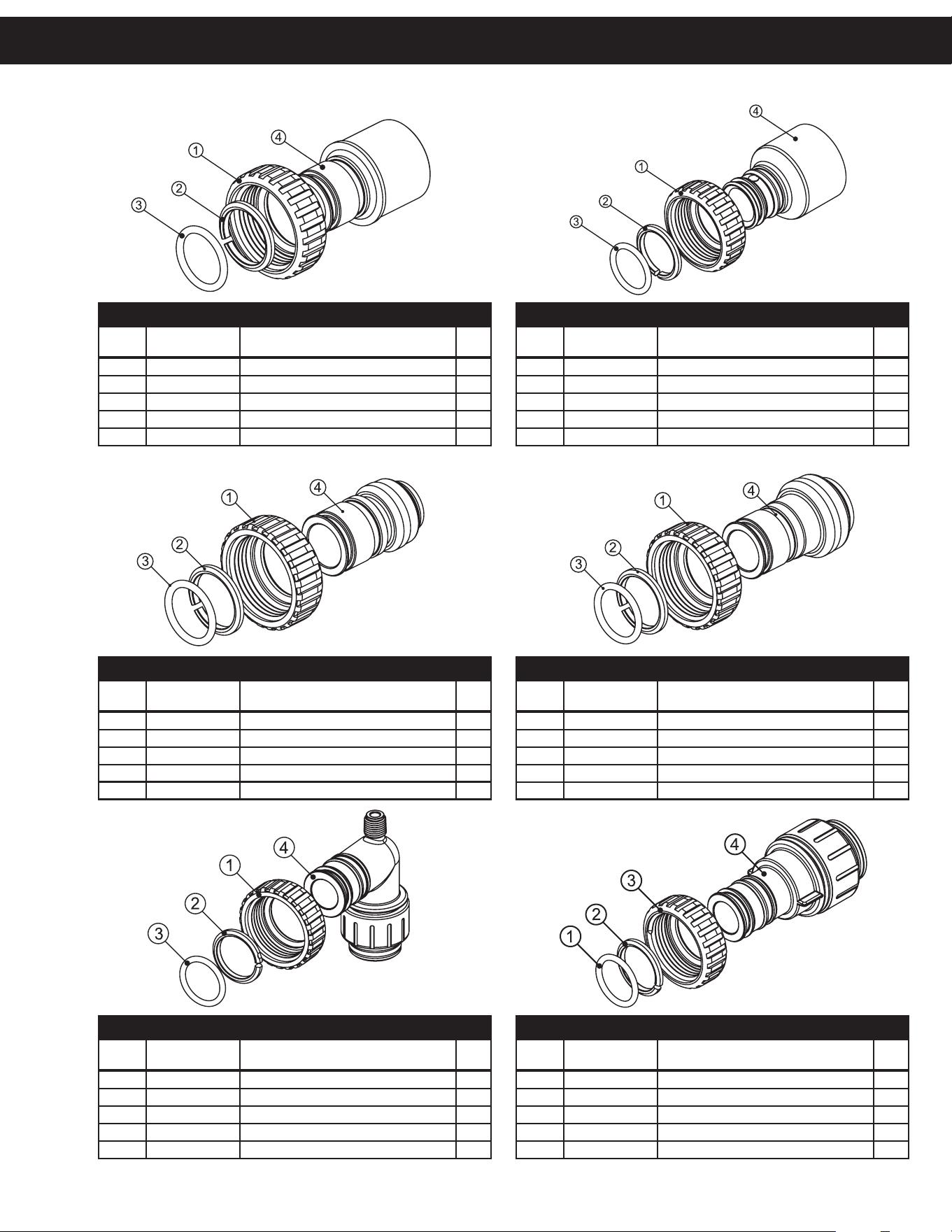
4
2
3
5
6
7
1
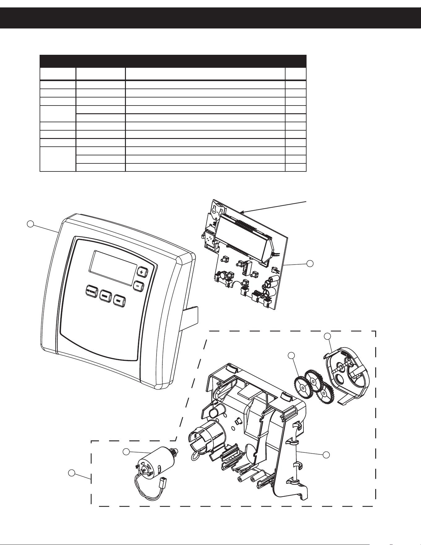
FRONT COVER AND DRIVE ASSEMBLY
Item No. Part No. Description Qty.
1 CV3540-NOLAB Black cover 1
2 CV3107-1 Motor 1
3 CV3106-1 Drive bracket & spring clip 1
4
CV3502WE PC board (used on chlorine generator models) 1
CV4022WU
PC board (standard) 1
5 CV3110 Drive gear, 12 x 36 3
6 CV3109 Drive gear cover 1
7 CV3002CC Drive assembly, CC -
not shown
CV3526 Transformer, 110V-15V, DC (used on chlorine generator models) 1
CV3186 Transformer, 110V-12V, AC (standard) 1
CV3543 Optional weather cover 1
NOTE: Battery Location
Replacement Parts
21
4
2
3
5
1
14
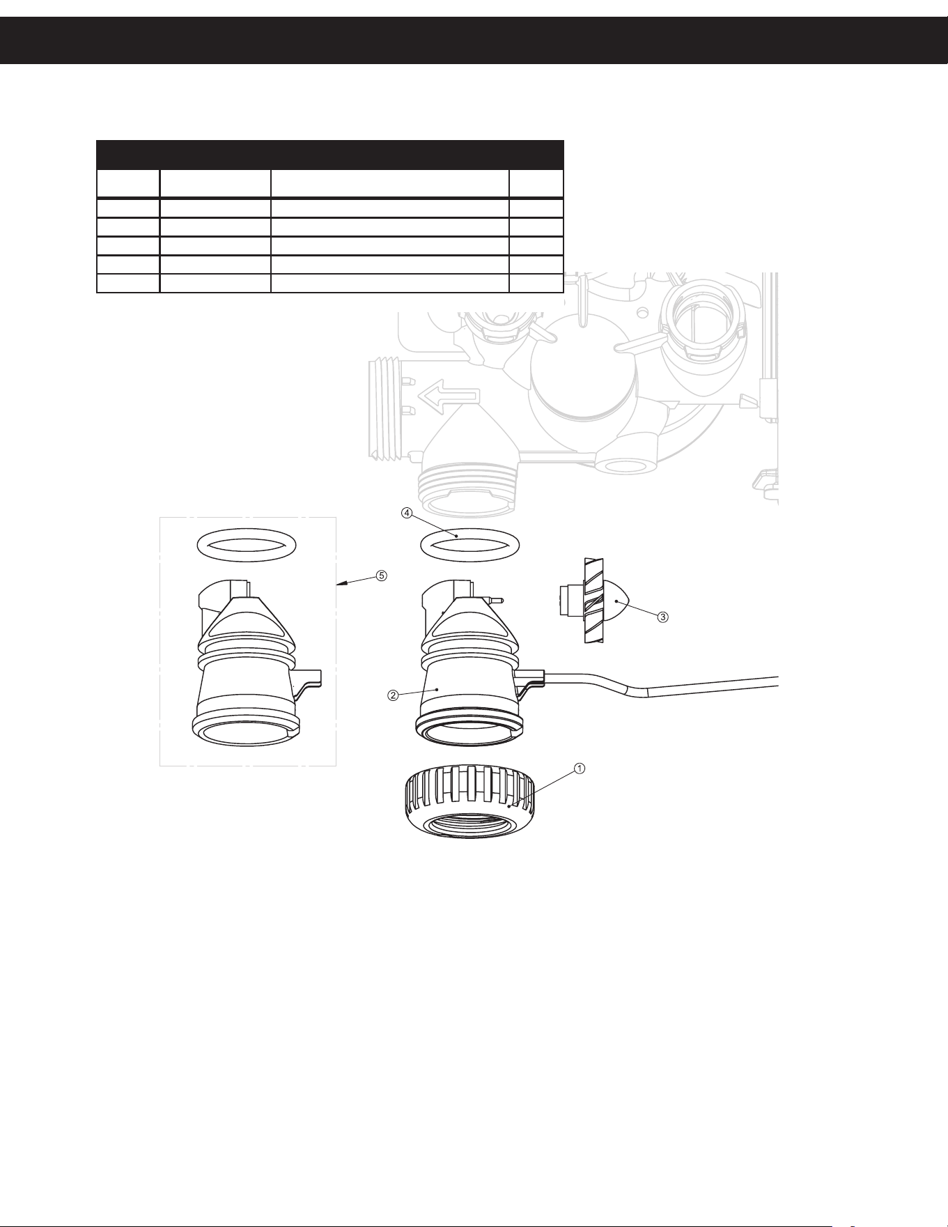
PISTON ASSEMBLY
Item No. Part No. Description Qty.
1 CV3005 1” spacer stack assembly 1
2 CV3004 Drive cap assembly 1
3 CV3135 O-ring 228 1
4
CV3011 1” piston assembly downflow 1
CV3011-01 1” piston assembly upflow 1
CV3407 1
.25” piston assembly downflow 1
5 CV3174 Regenerant piston 1
14 CV3541 Drive backplate 1
Replacement Parts
22
See pages
22-23
Replacement Parts
23
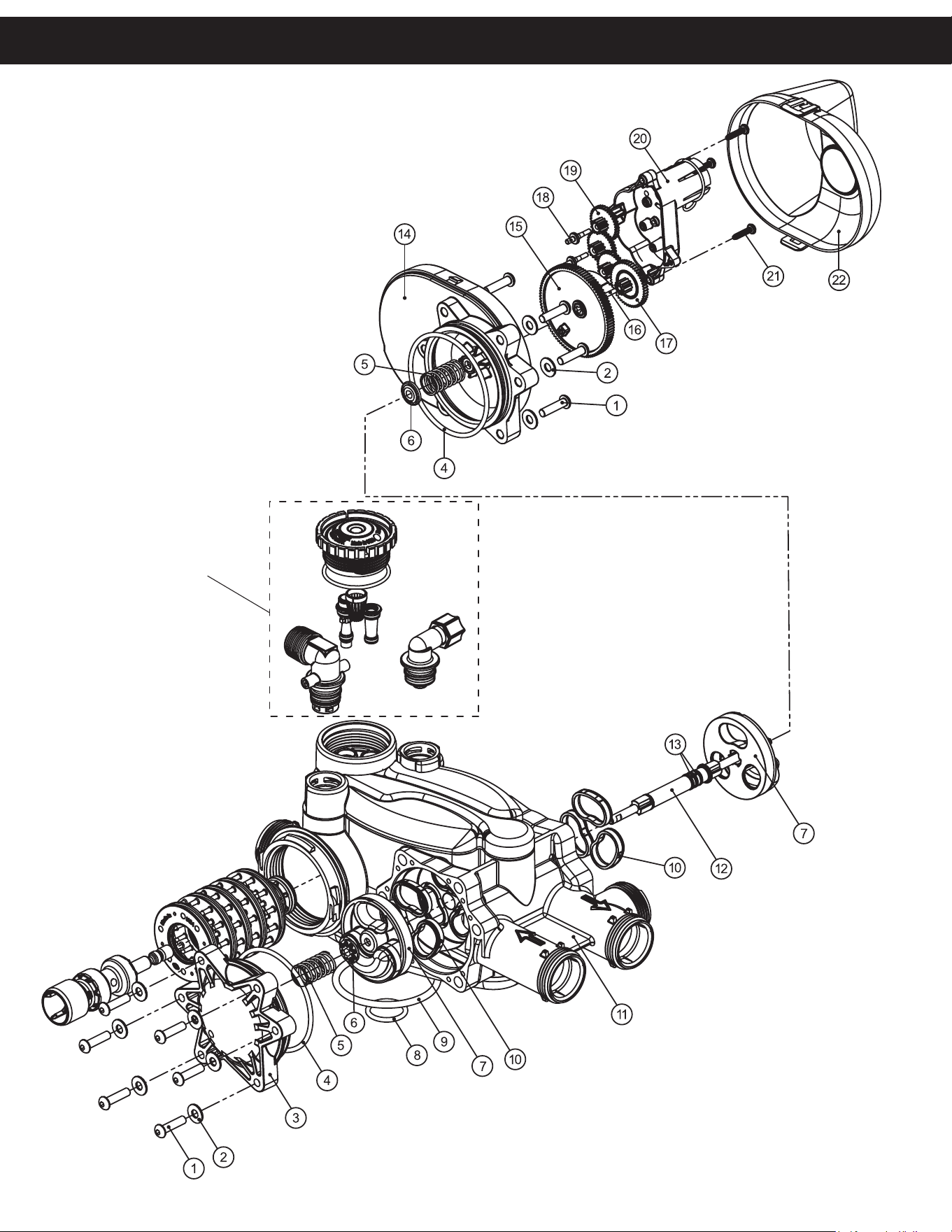
TWIN TRANSFER
Item No. Part No. Description Qty.
1 CV3470 Screw, BHC 1/4-20 x 1 SS 12
2 CV3724 Washer, flat SS 1/4 12
3 CV4005-01 T1 transfer cap assembly 1
4 CV4029 O-ring 236 2
5 CV4015 T1 transfer spring 2
6 CV4014 T1 transfer spring support 2
7 CV4036 T1 rotor disk assembly 2
8 CV3105 O-ring 215 (distributor tube) 1
9 CV3180 O-ring 337 1
10 CV4016 T1 transfer seal 6
11 CV3031 T1 body sft wtr regen 1
12 CV4023 T1 transfer drive shaft assembly 1
13 CV3287 O-ring 110 2
14 CV4006-01 T1 transfer drive cap assembly 1
15 CV4011-01 T1 transfer drive gear assembly 1
16 CV4012 T1 transfer drive gear axle 1
17 CV4013 T1 transfer reduction gear 1
18 CV3264 WS2H bypass reduction gear axle 3
19 CV3110 WS1 drive reducing gear 12 x 36 3
20 CV3262-01 WS1
.5 & 2 ALT/2BY reduction gear cover assembly 1
21 CV3592 Screw, #8-1 PHPN T-25 SS 3
22 CV4049 T1 cover assembly 1
not shown CV4043 T1 transfer motor assembly 1
not shown CV3151 WS1 nut 1 QC 1
not shown CV4055* Twin tank meter assembly 1
not shown CV4017-01 T1 interconnect fitting assembly 1
not shown D1400 1191 In/Out head 1
* This water meter should not be used as the primary monitoring device for
critical or health effect applications.
Replacement Parts
24
1
2
3
6
4
5
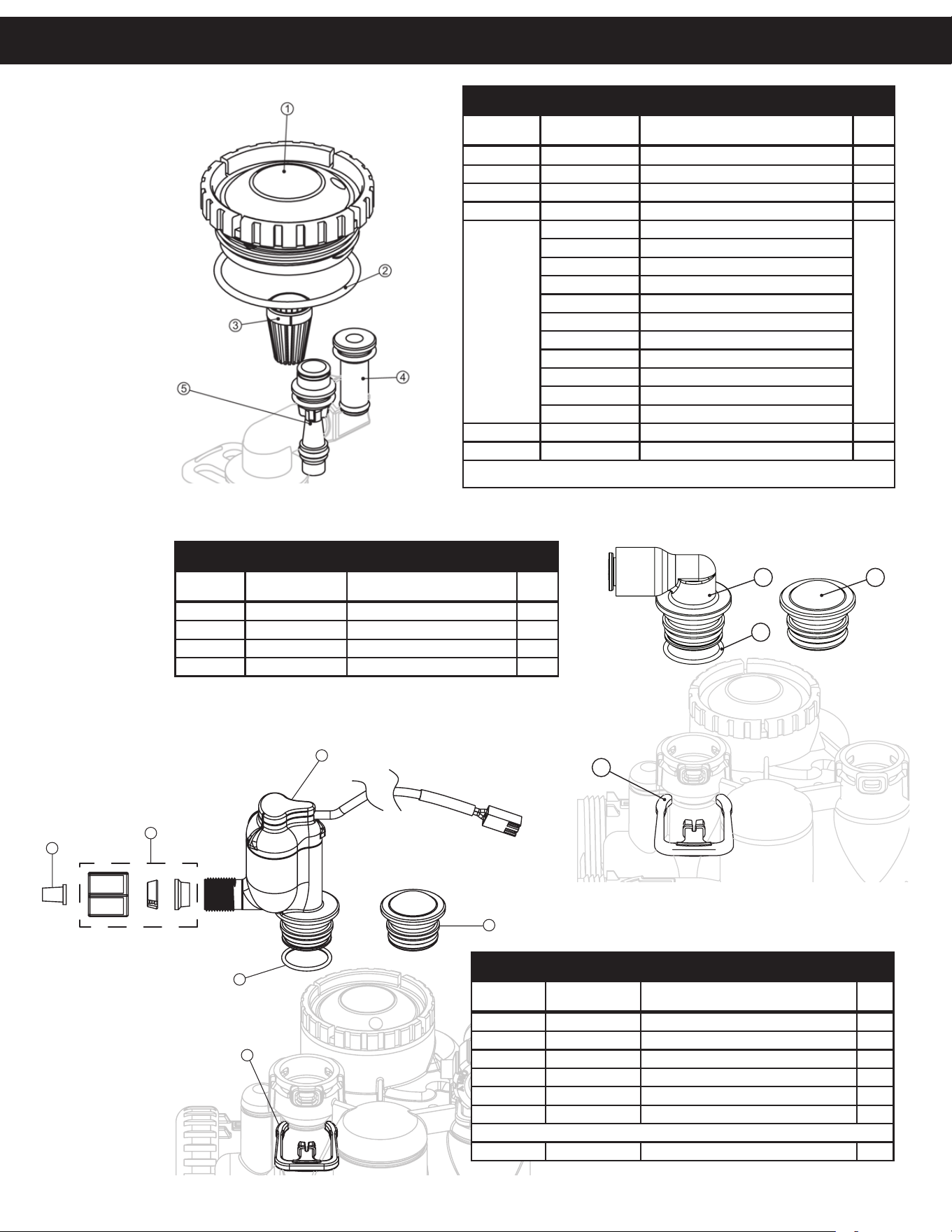
INJECTOR ASSEMBLIES
Item No. Part No. Description Qty.
1 CV3176 Injector cap 1
2 CV3152 O-ring 135 1
3 CV3177-01 Injector screen 1
4 CV3010-1Z Injector assembly plug 1
5
CV3010-1A A injector assembly,
black
1
CV3010-1B B injector assembly, brown
CV3010-1C C injector assembly, violet
CV3010-1D D injector assembly, red
CV3010-1E E injector assembly, white
CV3010-1F F injector assembly, blue
CV3010-1G G injector assembly, yellow
CV3010-1H H injector assembly, green
CV3010-1I I injector assembly, orange
CV3010-1J J injector assembly, light blue
CV3010-1K K injector assembly, light green
not shown CV3170 O-ring 011, lower *
not shown CV3171 O-ring 013, upper *
* The injector plug and the injector each use one lower and one upper o-ring
OPTIONAL CHLORINE GENERATOR ASSEMBLY
Item No. Part No. Description Qty.
1 CS1197 Polytube 3/8
” insert
1
2 JCPG-6PBLK Nut compression, 3/8” black 1
3 CV3395 Chlorinator, NPT WR body assembly 1
4 CV3163 O-ring 019 1
5 CH4615 Locking clip 1
6 CV3195-01 Refill port plug assembly 1
ASSEMBLIES
CV3395-A Complete chlorinator assembly 1
2
4
13
BRINE ELBOW ASSEMBLY
Item No. Part No. Description Qty.
1 CV3195-01 Refill port plug assembly 1
2 CH4615 Elbow locking clip 1
3 CV4144 3/8” Elbow, Parker fitting 1
4 CV3163 O-ring 019 1
Replacement Parts
25
DRAIN LINE ASSEMBLY 3/4”
Item No. Part No. Description Qty.
1 CH4615 Elbow locking clip 1
2 CPKP10TS8-BULK Optional insert, 5/8” tube 1
3 CV3192 Optional nut, 3/4” drain elbow 1
4 CV3158-02 Drain elbow, 3/4” NPT with O-ring 1
5 CV3163 O-ring 019 1
6 CV3159-01 DLFC retainer assembly 1
7
CV3162-007 0.7 DLFC for 3/4” elbow
1
CV3162-010
1.0 DLFC for 3/4” elbow
CV3162-013
1.3 DLFC for 3/4” elbow
CV3162-017
1.7 DLFC for 3/4” elbow
CV3162-022
2.2 DLFC for 3/4” elbow
CV3162-027
2.7 DLFC for 3/4” elbow
CV3162-032
3.2 DLFC for 3/4” elbow
CV3162-042
4.2 DLFC for 3/4” elbow
CV3162-053
5.3 DLFC for 3/4” elbow
CV3162-065
6.5 DLFC for 3/4” elbow
CV3162-075 7.5 DLFC for 3/4” elbow
CV3162-090 9.0 DLFC for 3/4” elbow
CV3162-100 10.0 DLFC for 3/4” elbow
8 CV3331 Drain elbow and retainer assembly
Items 2 and 3, nut and insert are only used with 1/2” I.D.
by 5/8” O.D. polytubing. For other piping material, the
3/4” NPT is used.
Proper DLFC orientation
directs water flow towards
the washer face with
rounded edge and lettering.
Water
Flow
3/4”
NPT
Replacement Parts
26
WATER METER & METER PLUG
Item No. Part No. Description Qty.
1 CV3151 Nut, 1” QC 1
2 CV3003 Meter assembly, includes items 3 & 4 1
3 CV3118-01 Turbine assembly 1
4 CV3105 O-ring 215 1
5 CV3003-01 Meter plug assembly 1
Replacement Parts
27
SAFETY FLOAT BRINE ELBOW
Item # Legacy Part # Current Part # Description Qty.
CV4144 100245015 3/8” elbow cap, Parker fitting (no flow control) 1
CV4144-03 100242646 3/8” elbow cap, Parker fitting (w/flow control) 1
CH4612 100245861 1/2” elbow cap 1
1
2
7
8
6
3
5
4
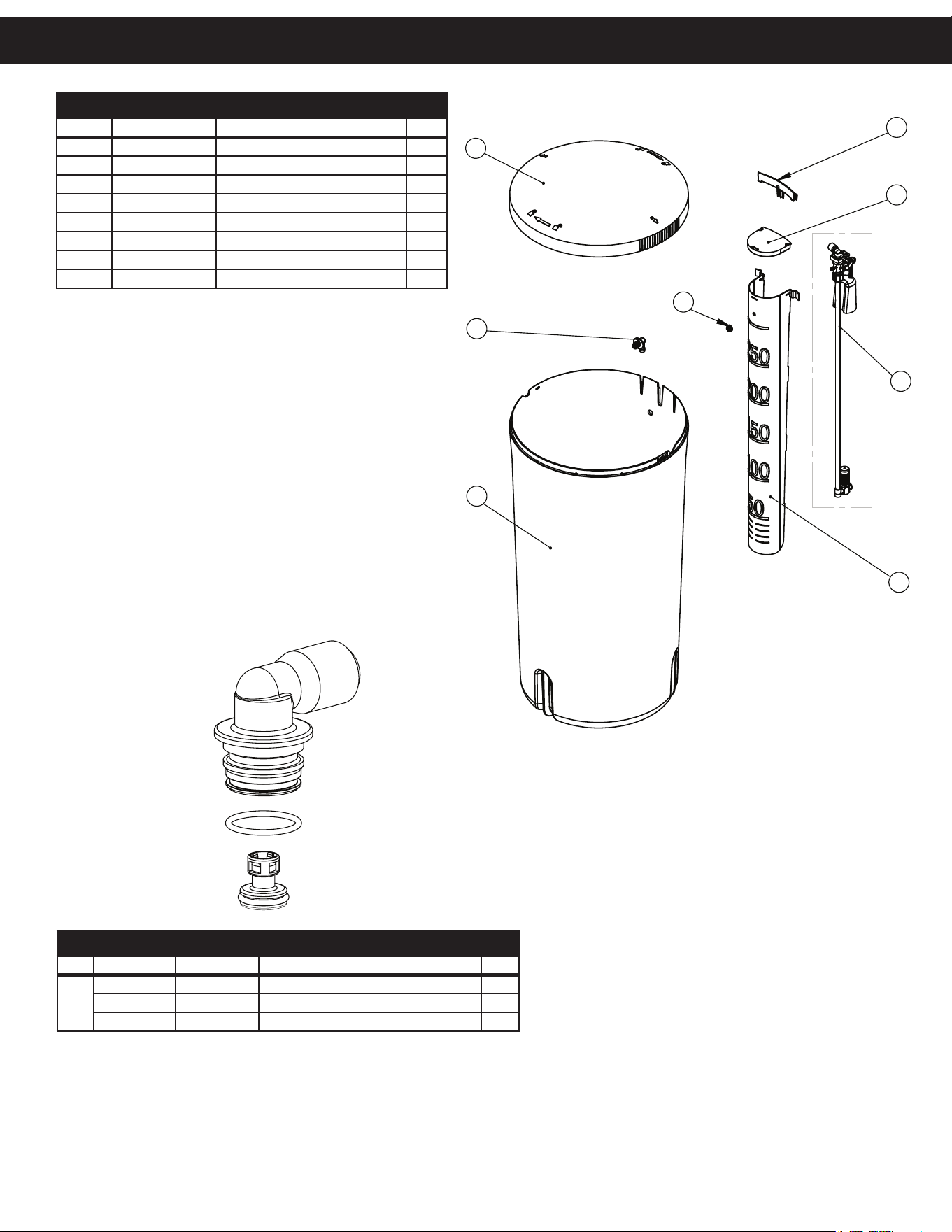
ITEM #
PART #
DESCRIPTION
QTY.
1 100379336
18" x 36" BRINE TANK
1
2 100379337
BRINE TANK LID
1
3 100379338
BRINE WELL
1
4 100399465
SAFETY SHUTOFF ASSEMBLY,
0.5 GPM
1
5 100245864
SAFETY SHUTOFF NUT
1
6 100379339
BRINE WELL COVER
1
7 100397461
BRINE TANK GROMMET
1
8 100238195
CABINET OVERFLOW ELBOW
1
BRINE TANK ASSEMBLY
Item # Current Part # Description Qty.
1 100379336 19” x 37” Brine tank 1
2 100379337 Brine tank lid 1
3 100379338 Brine well 1
4 100399465 Safety shutoff assembly, 0.5 gpm 1
5 100245864 Safety shutoff nut 1
6 100379339 Brine well cover 1
7 100397461 Brine well retainer 1
8 100238195 Cabinet overflow elbow 1
Replacement Parts
28
2
3
4
5
6
7
8
10
1
9
11
1
2
3
4
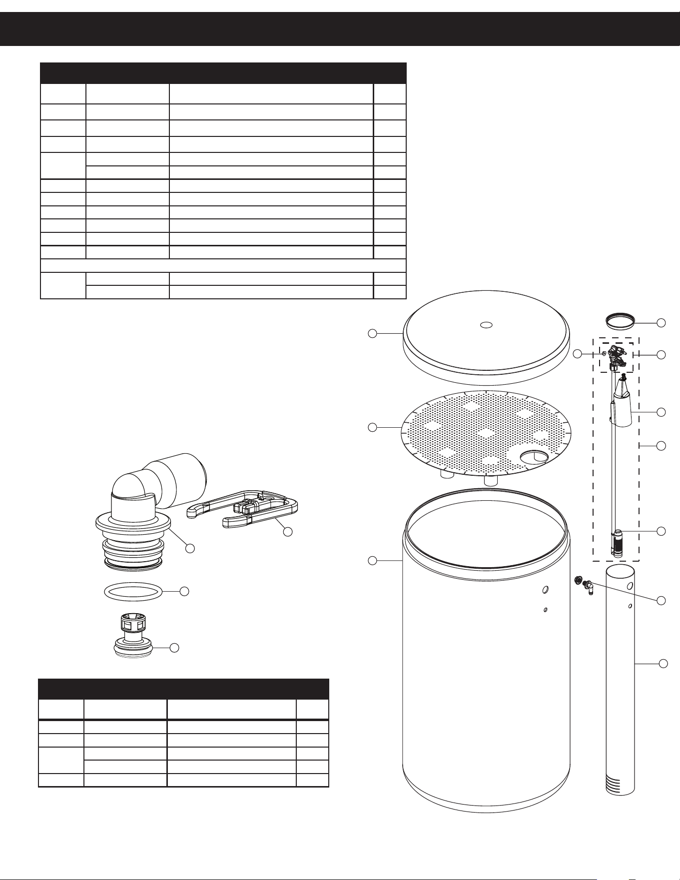
BRINE TANK ASSEMBLY
Item No. Part No. Description Qty.
CG2180 Brine tank cover, standard 1
CH1080 Optional 24” diameter salt grid 1
CG22441CB1C00 24” x 41” brine tank, black 1
4
CH1030-29S 4” x 29” slotted brine well (18 x 33 BT) 1
CH1030-36S 4” x 36” slotted brine well (18 x 40, 24 x 40 BT’s) 1
5 CH1018 2 piece overflow set 1
6 CH4500-48 474 air check assembly, 1/2” x 48” 1
7 CH4640-32 474 float assembly, 32” w/ 2 grommets 1
8 CH4600-50 474 safety brine valve w/
.5 gpm glow control 1
9 CH7016 Cap 4” brine well 1
10 CH4626 Nut safety brine valve stand off 1
ASSEMBLIES
11
CH4700-29WR-1
.5 gpm safety float assembly, 18” x 33”
CH47
00-36.5WR-1 .5 gpm safety float assembly, 18” x 40”
2
3
4
5
6
7
8
10
1
9
11
1
2
3
4
SAFETY FLOAT BRINE ELBOW
Item No. Part No. Description Qty.
1 CH4655 474 .5 gpm flow control 1
2 CV3163 O-Ring 019 1
3
CV4144 3/8” elbow cap, Parker fitting 1
CH4612 1/2” elbow cap 1
4 CH4615 Elbow locking clip 1
Replacement Parts
29
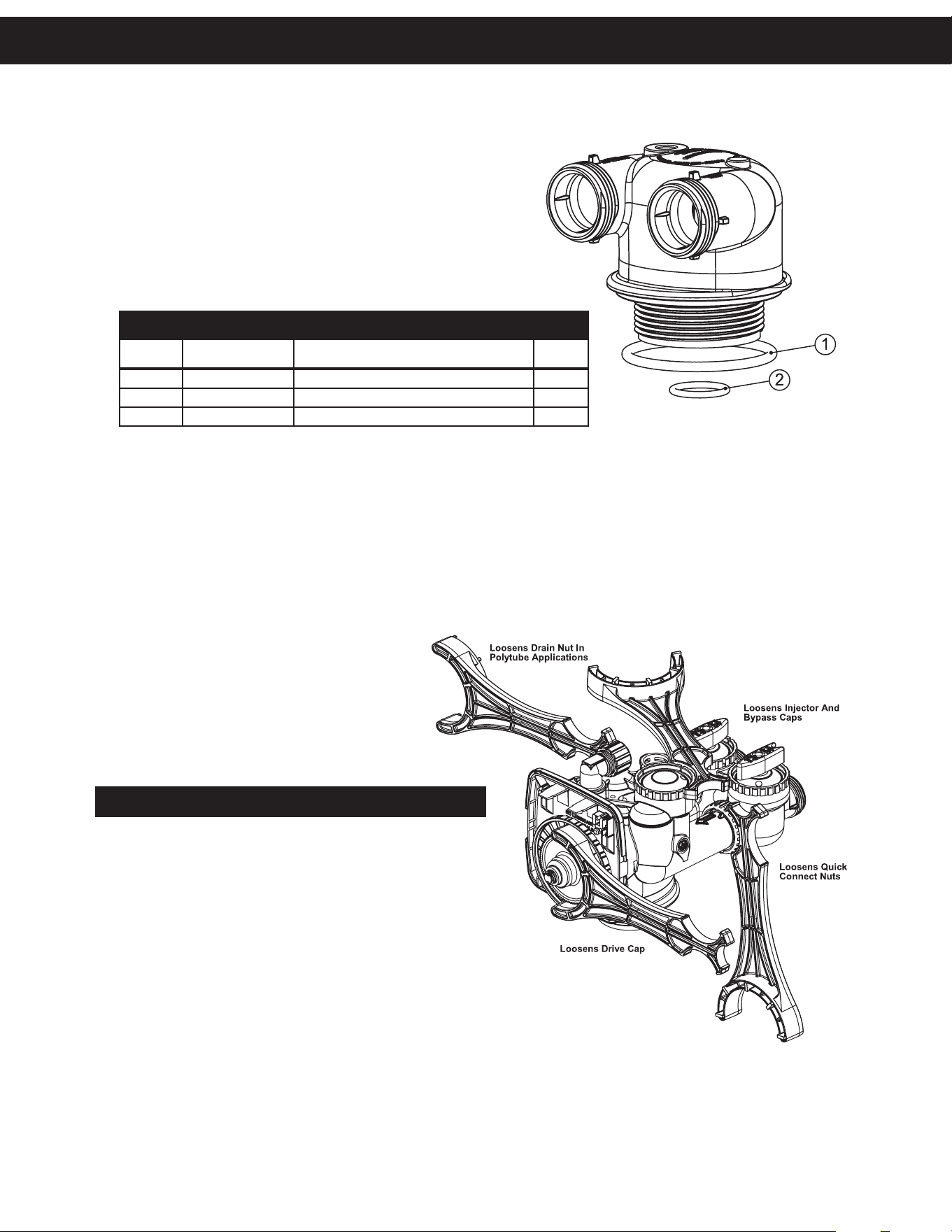
Although no tools are necessary to assemble
or disassemble the valve, the Service Wrench,
(shown in various positions on the valve) is
available to aid in assembly or disassembly.
SERVICE WRENCH - CV3193-02
IN/OUT HEAD (FOR TANK B)
Item No. Part No. Description Qty.
CD1400 1191 In/Out head (includes O-rings) 1
1 CV3180 O-ring 337 1
2 CV3105 O-ring 215 1
Replacement Parts
2
3
4
5
6
7
8
10
1
9
11
1
2
3
4
Replacement Parts
30
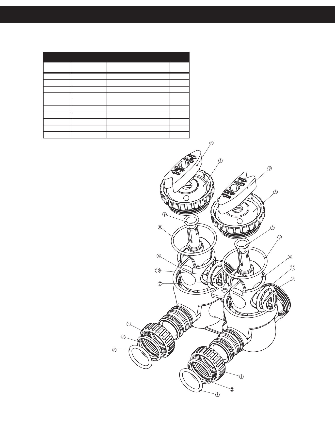
BYPASS VALVE
Item No. Part No. Description Qty.
1 CV3151 Nut, 1” quick connect 2
2 CV3150 Split ring 2
3 CV3105 O-ring 215 2
4 CV3145 Bypass rotor, 1” 2
5 CV3146 Bypass cap 2
6 CV3147 Bypass handle 2
7 CV3148 Bypass rotor seal retainer 2
8 CV3152 O-ring 135 2
9 CV3155 O-ring 112 2
10 CV3156 O-ring 214 2
Replacement Parts
31
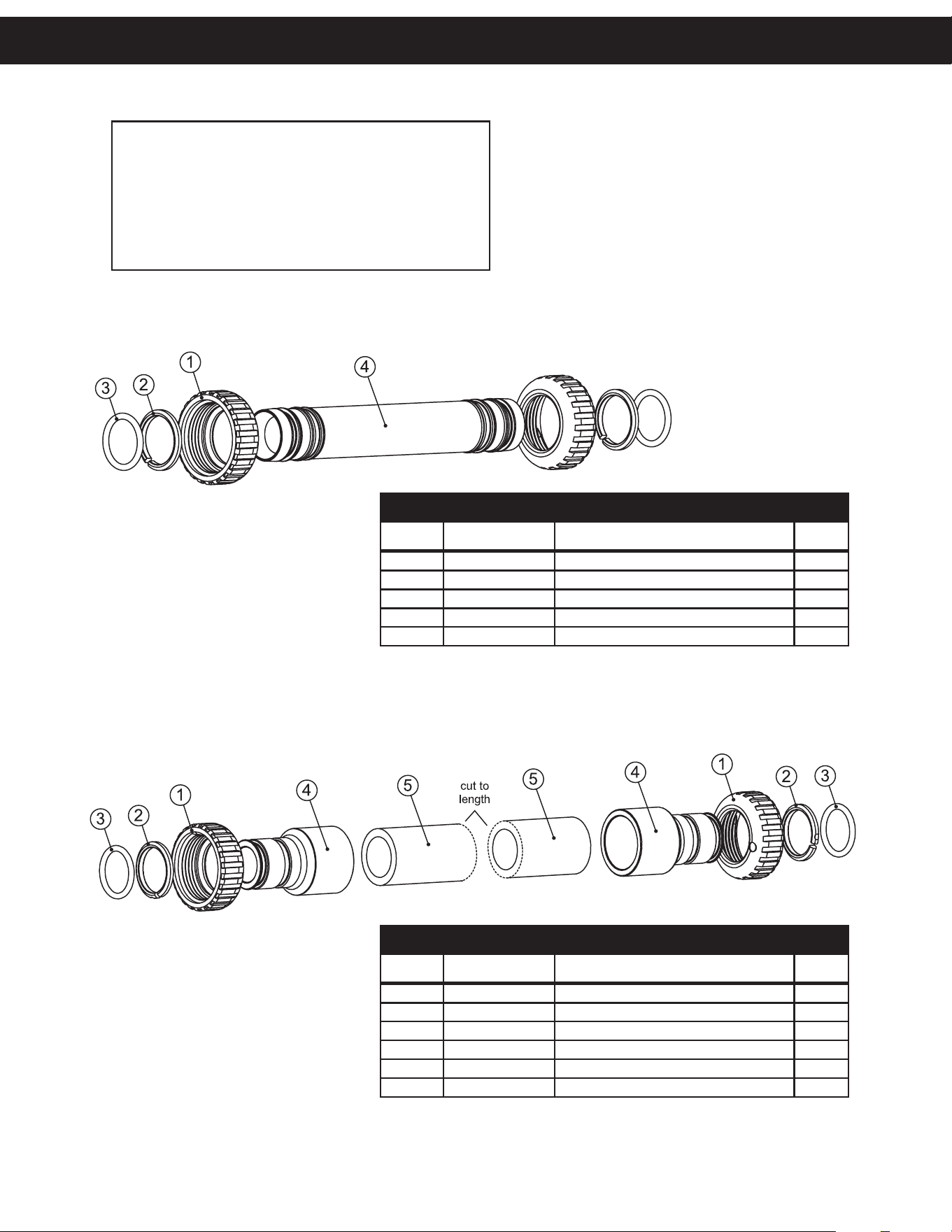
INTERCONNECT FITTING ASSEMBLY (UP TO 10” TANKS)
Item No. Part No. Description Qty.
CV4017-01 Interconnect kit for tanks up to 10” 1
1 CV3151 Nut, 1” QC 4
2 CV3150 Split ring 4
3 CV3105 O-ring 215 4
4 CV4017 Interconnect fitting 2
INTERCONNECT FITTING ASSEMBLY (12” & LARGER TANKS)
Item No. Part No. Description Qty.
CV4052-01 Interconnect kit for tanks 12” and larger 1
1 CV3151 Nut, 1” QC 4
2 CV3150 Split ring 4
3 CV3105 O-ring 215 4
4 CV3352 1-1/4” & 1-1/2” PVC solvent fitting 4
5 CV4052 Pipe, PVC SCH 80 1-1/4” x 20” 2
Fitting Installation Instructions
• Installation fittings are designed to accommodate
minor plumbing misalignments, but are not designed
to support the weight of a system or the plumbing.
• Slide nut on first, then the split ring and O-ring.
• Hand tighten the nut only.
Installation Fiing AssembliesReplacement Parts
32
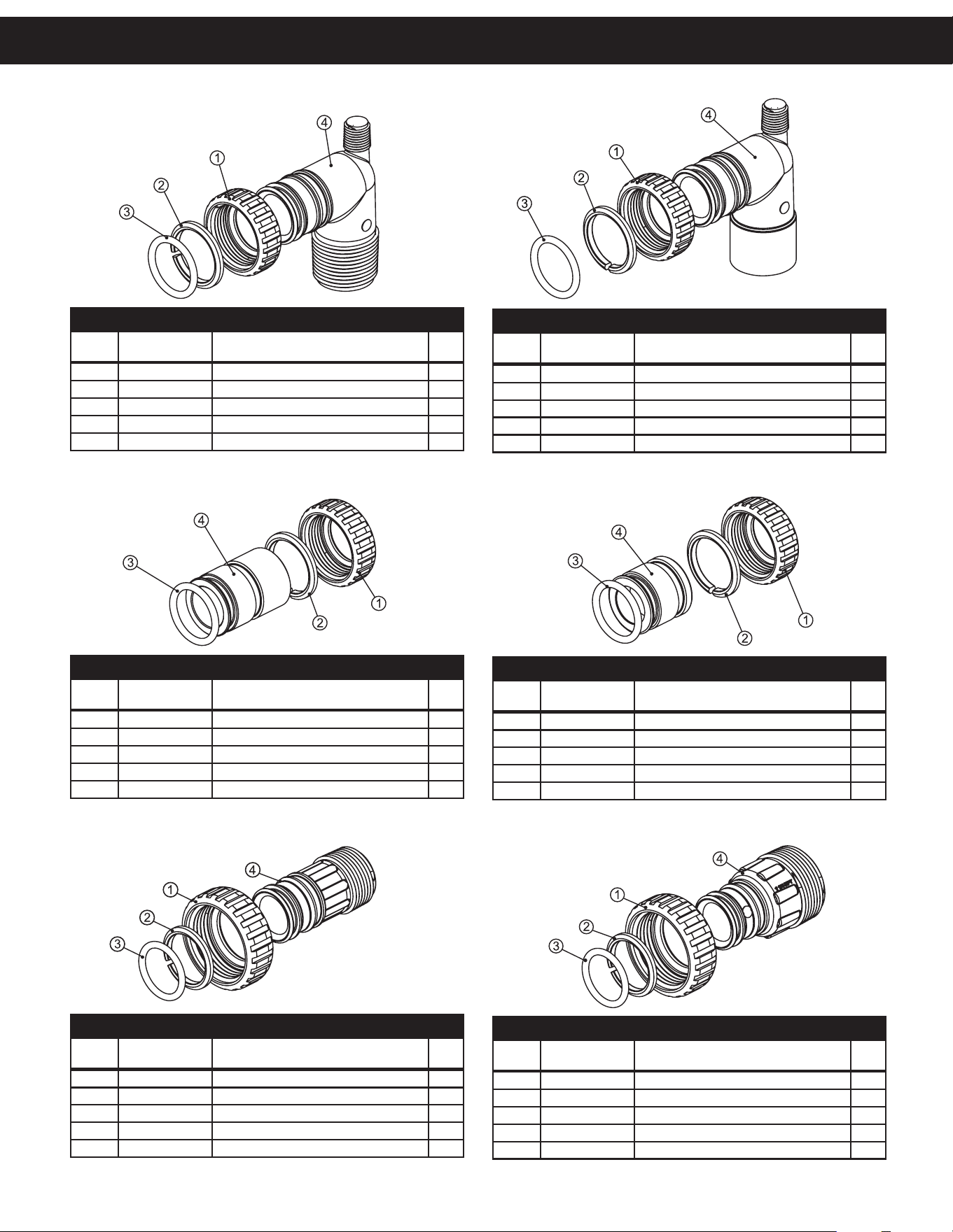
1” PVC MALE NPT ELBOW
Item
No.
Part No. Description Qty.
CV3007 1” PVC male NPT elbow assembly 2
1 CV3151 Nut, 1” quick connect 2
2 CV3150 Split ring 2
3 CV3105 O-ring 215 2
4 CV3149 Fitting 2
3/4” & 1” PVC SOLVENT ELBOW
Item
No.
Part No. Description Qty.
CV3007-01 3/4” & 1” PVC solvent elbow assembly 2
1 CV3151 Nut, 1” quick connect 2
2 CV3150 Split ring 2
3 CV3105 O-ring 215 2
4 CV3189 Fitting 2
1” BRASS SWEAT
Item
No.
Part No. Description Qty.
CV3007-02 1” brass sweat assembly 2
1 CV3151 Nut, 1” quick connect 2
2 CV3150 Split ring 2
3 CV3105 O-ring 215 2
4 CV3188 Fitting 2
3/4” BRASS SWEAT
Item
No.
Part No. Description Qty.
CV3007-03 3/4” brass sweat assembly 2
1 CV3151 Nut, 1” quick connect 2
2 CV3150 Split ring 2
3 CV3105 O-ring 215 2
4 CV3188-01 Fitting 2
1” PLASTIC MALE NPT
Item
No.
Part No. Description Qty.
CV3007-04 1” plastic male NPT assembly 2
1 CV3151 Nut, 1” quick connect 2
2 CV3150 Split ring 2
3 CV3105 O-ring 215 2
4 CV3164 Fitting 2
1-1/4” PLASTIC MALE
Item
No.
Part No. Description Qty.
CV3007-05 1-1/4” plastic male assembly 2
1 CV3151 Nut, 1” quick connect 2
2 CV3150 Split ring 2
3 CV3105 O-ring 215 2
4 CV3317 Fitting 2
Installation Fiing Assemblies
33
1-1/4” & 1-1/2” PVC SOLVENT
Item
No.
Part No. Description Qty.
CV3007-07 1-1/4” & 1-1/2” PVC solvent assembly 2
1 CV3151 Nut, 1” quick connect 2
2 CV3150 Split ring 2
3 CV3105 O-ring 215 2
4 CV3352 Fitting 2
1-1/4” & 1-1/2” BRASS SWEAT
Item
No.
Part No. Description Qty.
CV3007-09 1-1/4 & 1-1/2” brass sweat assembly 2
1 CV3151 Nut, 1” quick connect 2
2 CV3150 Split ring 2
3 CV3105 O-ring 215 2
4 CV3375 Fitting 2
1” BRASS SHARK BITE
Item
No.
Part No. Description Qty.
CV3007-13 1” brass Shark Bite assembly 2
1 CV3151 Nut, 1” quick connect 2
2 CV3150 Split ring 2
3 CV3105 O-ring 215 2
4 CV3629 Fitting 2
3/4” BRASS SHARK BITE
Item
No.
Part No. Description Qty.
CV3007-12 3/4” brass Shark Bite assembly 2
1 CV3151 Nut, 1” quick connect 2
2 CV3150 Split ring 2
3 CV3105 O-ring 215 2
4 CV3628 Fitting 2
3/4” JOHN GUEST ELBOW
Item
No.
Part No. Description Qty.
CV3007-15 3/4” John Guest elbow assembly 2
1 CV3151 Nut, 1” quick connect 2
2 CV3150 Split ring 2
3 CV3105 O-ring 215 2
4 CV3790 Fitting 2
1” JOHN GUEST
Item
No.
Part No. Description Qty.
CV3007-17 1” John Guest elbow assembly 2
1 CV3151 Nut, 1” quick connect 2
2 CV3150 Split ring 2
3 CV3105 O-ring 215 2
4 CV4045 Fitting 2
Installation Fiing AssembliesInstallation Fiing Assemblies

34
This page intentionally left blank.
35
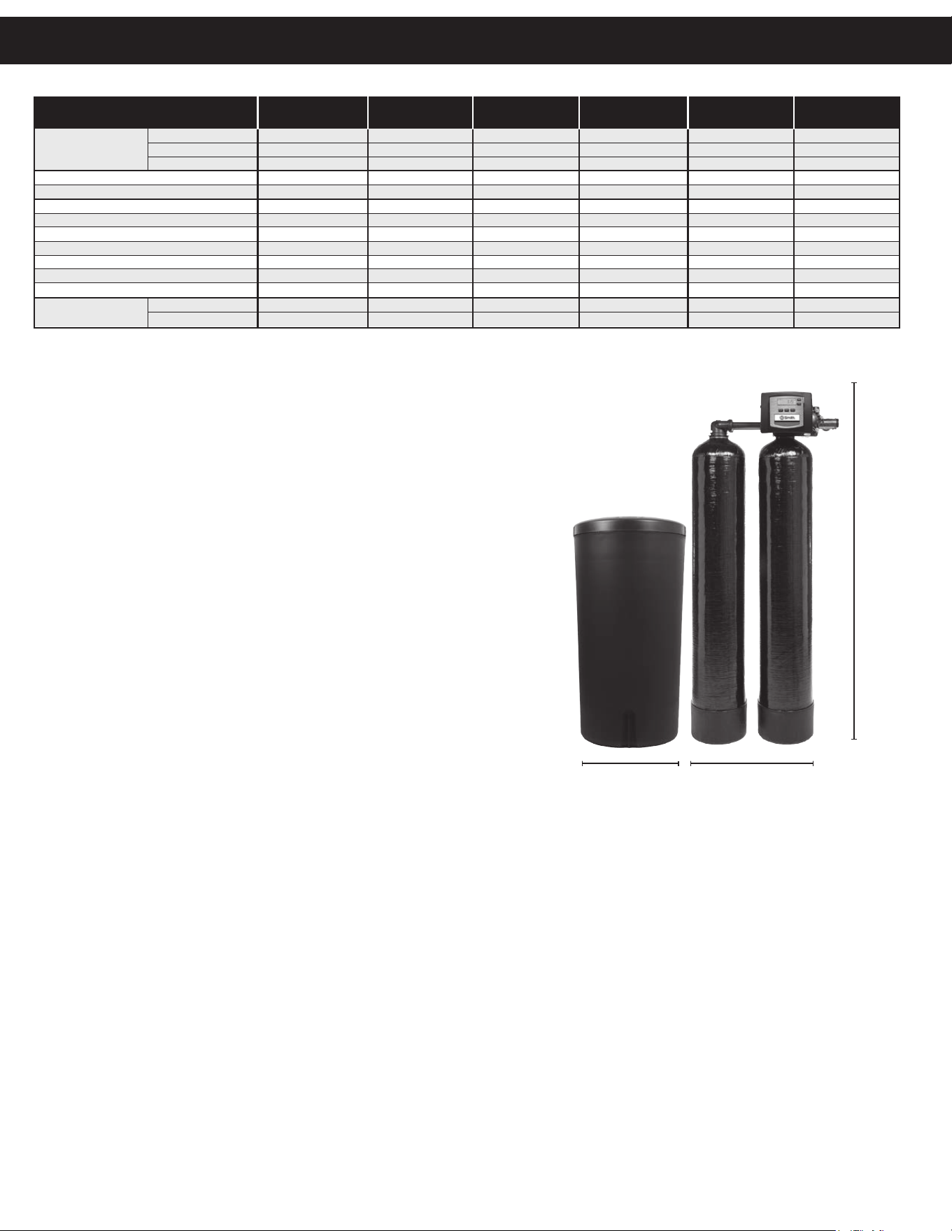
1
All water softeners are factory preset at medium salting.
Note: Influent waters must be at least 3 GPG hardness and 80 TDS. A calcite or corosex unit may be
needed for correct operation. Capacity will be reduced by the gallons used during regeneration.
2
The pH listed is the minimum for the influent water.
3
Unit not tested for capacity at these peak flow rates. Water quality may vary.
MODEL 0024-10 0030-10 0045-10 0075-10 0090-10 0120-10
Maximum
25,600 @ 9.0 32,000 @ 15.0 48,800 @ 21.0 72,800 @ 24.0 90,000 @ 45.0 120,000 @ 60.0
Medium
21,600 @ 6.0 28,400 @ 9.0 44,400 @ 15.0 64,200 @ 18.0 75,000 @ 30.0 100,000 @ 40.0
Minimum
15,600 @ 3.0 23,600 @ 6.0 35,400 @ 9.0 53,000 @ 12.0 60,000 @ 18.0 80,000 @ 24.0
Amount of Resin Media (Cu. Ft.)
.85 1.0 1.5 2.5 3 4
Maximum Water Hardness (GPG) 50 75 100 100 100 100
2
Minimum pH Required 7.0 7.0 7.0 7.0 7.0 7.0
3
Peak Flow Rate (GPM @ P-PSI) 11.4 @ 15.0 17.1 @ 15.0 14.3 @ 15.0 18.5 @ 15.0 27.0 @ 25.0 29.0 @ 25.0
Continuous Flow Rate (GPM @ P-PSI) 5.0 @ 5.4 5.0 @ 2.8 5.0 @ 3.8 5.0 @ 2.4 20.0 @ 15.0 22.0 @ 15.0
Water Pressure Range (PSI)
30-100 30-100 30-100 30-100 30-100 30-100
Water Temperature (ºF) 33-100 33-100 33-100 33-100 33-100 33-100
Electrical Requirements (volts-hertz) 110-50/60 110-50/60 110-50/60 110-50/60 110-50/60 110-50/60
Pipe Size 1” 1” 1” 1” 1” 1”
Total Dimensions:
Media Tank a nd Valve
27”W x 52”H 29”W x 52”H 29”W x 62”H 31”W x 62”H 32”W x 74”H 34”W x 74”H
Brine Tank
19”W x 37”H 19”W x 37”H 19”W x 37”H 19”W x 37”H 19”W x 37”H 24”W x 41”H
1
Capacity:
(Grains/Lbs. NaCI)
Only the 0030-10 through the 0075-10 sizes are approved in the state of Wisconsin.
Height
Width
C40 Twin Specifications

36
This page intentionally left blank.

37
A. O. Smith Commercial Limited Warranty
WHO IS COVERED
This limited warranty is provided by A. O. Smith and applies only to the original owner who purchased and installed the A. O. Smith product for
use at the original installa on site. This warranty is non-transferable.
WHAT IS COVERED
This warranty covers defects in materials or workmanship in your A. O. Smith product when properly installed, used under normal opera ng
condi ons, and maintained according to A. O. Smith guidelines and local plumbing codes.
WARRANTY COVERAGE PERIODS
All warranty coverage periods run from the date of purchase, or 60 days a er the date of manufacture if the purchase date cannot be verifi ed.
For a period of FIVE YEARS: Complete valve.
Brine tank.
Media tank – except for damages due to freezing, high pressure (120 PSI and above), extreme temperature
(100° F and above) or a vacuum on the system.
For a period of ONE YEAR: All other parts and components.
This warranty does not cover any equipment purchased for use in applica ons in which the product is not suited. It is the responsibility of the
buyer to determine if a product is suitable for a par cular applica on.
WHAT A. O. SMITH WILL DO
If a component is found defec ve during its warranty period, A. O. Smith will repair or replace the defec ve part at its discre on with an iden cal
part or a comparable part if an iden cal replacement is not available. The owner is responsible for freight charges from the factory and local
dealer service or labor fees. The warranty period for any replacement will run for the balance of the original warranty period.
WHAT A. O. SMITH WILL NOT DO
A. O. Smith will not pay for labor to remove or reinstall parts, shipping damage, water damage resul ng from system failure, dealer trip charges,
unauthorized service, damage caused by failure to follow installa on instruc ons, or replacement fi lters, media, or rou ne maintenance.
WHAT IS NOT COVERED
1. This warranty does not cover: damage caused by accident, misuse, neglect, fi re, fl ood, freezing, or other acts of God, improper
installa on, altera on, vacuum damage, chemicals, opera on outside specifi ca ons, cosme c issues, non-A. O. Smith parts,
installa on costs, improper plumbing connec ons, lack of maintenance, use with water that is microbiologically unsafe, loss of use,
property damage, incidental or consequen al damages, freight, or water damage. A. O. Smith disclaims all implied warran es to the
fullest extent permi ed by law.
2. Except when specifi cally prohibited by the applicable state law, the Owner, and not the Manufacturer, shall be liable for and shall pay
for all charges for labor or other expenses incurred in the removal, repair or replacement of any component part(s) claimed to be
defec ve or any expense incurred to remedy any defect in the product. Such charges may include, but are not necessarily limited to:
a. All freight, shipping, handling and delivery costs of forwarding a new component or replacement part(s) to the owner.
b. All costs necessary or incidental in removing the defec ve component part(s) and installing a new component part(s).
c. Any material required to complete, and/or permits required for, installa on of a new component or replacement part(s).
d. All costs necessary or incidental in returning the defec ve component part(s) to a loca on designated by the Manufacturer.
e. This warranty provides specifi c legal rights and limita ons, but you may have other rights under applicable state law.
OWNER RESPONSIBILITIES
Owners must install and operate the system per A. O. Smith specifi ca ons, comply with local codes, prevent freezing or vacuum damage,
operate within pressure/temperature limits, replace media/fi lters as required, use only approved components, and retain proof of purchase and
installa on date. Either proof of purchase from an authorized dealer or proof of serial number, along with proof of proper installa on, will be
required to obtain warranty coverage.
HOW TO OBTAIN SERVICE
If service is required, contact your installa on dealer or an authorized A. O. Smith dealer. If unavailable, ship the defec ve component (freight
prepaid) to: A. O. Smith, 1000 Prospect Ct., Appleton, WI 54914. A. O. Smith will return repaired or replaced parts freight collect. Registra on is
not required to be covered by this warranty.
LIMITATION OF REMEDIES
The owner’s sole remedy is repair or replacement of defec ve parts. A. O. Smith is not liable for incidental, consequen al, water, or property
damages. Some states do not allow such limita ons; in such states, these may not apply.
STATE LAW RIGHTS
This warranty provides specifi c legal rights; addi onal rights may vary by state.
© 2026 A. O. Smith, Inc. All rights reserved.
A. O. Smith Commercial
Limited Warranty
38
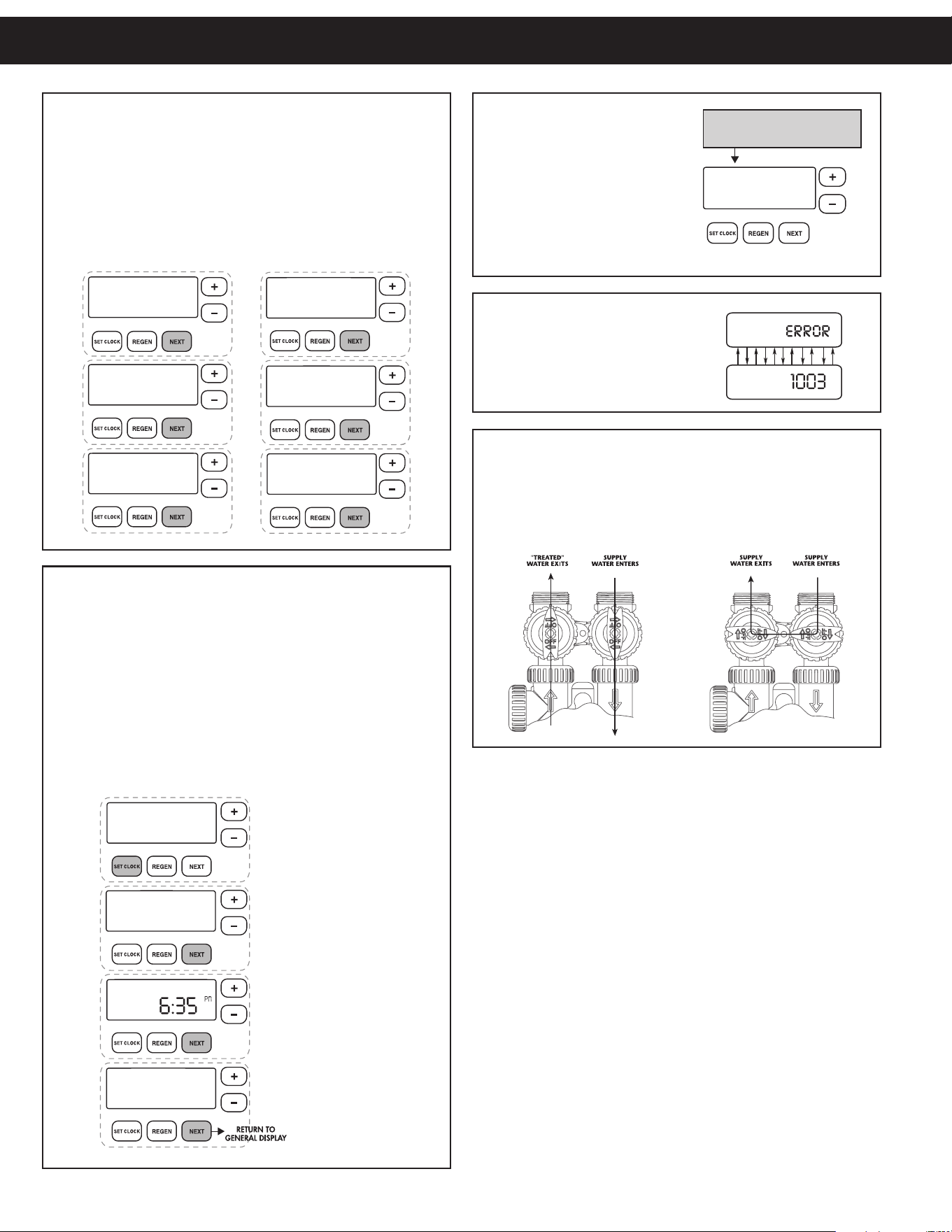
MANUAL REGENERATION
NOTE: For softeners, if brine tank
does not contain salt, fill with salt
and wait at least two hours before
regeneration. If you need to initiate
a manual regeneration immediately,
press and hold regen until valve
motor starts (typically 3 seconds).
ERROR
If the display toggles between “Error”
and an error code (i.e. a number), call
a service technician and report the
error code.
BYPASS VALVE OPERATION
To shut off water to the system, position arrow handles as shown in
the bypass operation diagram below. If your valve doesn’t look like
the diagram below, contact your service technician for instructions
on how to shut off water.
NORMAL OPERATION BYPASS OPERATION
GENERAL OPERATION
When the system is operating, one of six displays will be shown:
1. time of day/gpm
2. flow rate
3. vacation mode
4. capacity remaining
5. days to a regen
6. dealer name and phone number (optional screen)
Pressing next will toggle between the six choices.
TO SET TIME OF DAY
In the event of a prolonged power outage, time of day flashes,
indicating that this needs to be reset. All other information will be
stored in memory no matter how long the power outage.
1. Accessed by pressing set clock
2. Adjust hours with + and — buttons, AM/PM toggles at 12
3. Press next
4. Adjust minutes with + and — buttons
5. Press next
6. Adjust current day with + and — buttons
7. Press next to complete and return to normal operation
ON VACATION
NO
DAYS TO A REGEN
GPM
3
A
CAPACITY REMAINING
GPM GAL
1600
A
FLOW RATE
GPM
8.0
TIME OF DAY MON
GPM
2:40A
A
PM
PHONE NUMBER
DEALER NA
ON VACATION
NO
DAYS TO A REGEN
GPM
3
A
CAPACITY REMAINING
GPM GAL
1600
A
FLOW RATE
GPM
8.0
TIME OF DAY MON
GPM
2:40A
A
PM
PHONE NUMBER
DEALER NA
CURRENT DAY
SET
MON
TIME MINUTES
SET
TIME HOUR
SET
2:00
AM
REGEN TODAY MON
GPM
2:408
PM
REGEN TODAY and TIME OF DAY
will flash alternately if a regeneration
is expected tonight.
Quick Reference Guide
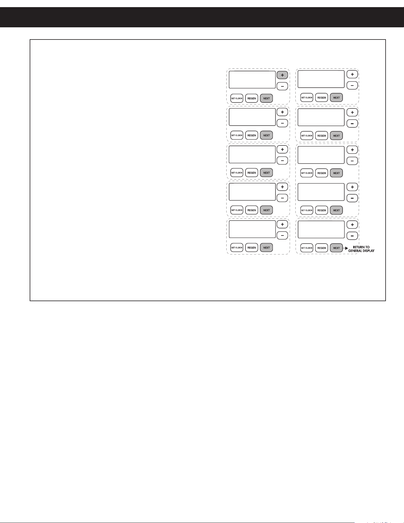
39
ADJUST HARDNESS, DAYS BETWEEN REGENERATION, TIME OF REGENERATION AND ALARM BUZZER
For initial set-up or to make adjustments, please complete the following steps.
1. Accessed by pressing next and + button simultaneously
2. Adjust hardness using + and — buttons
3. Press next
4. Adjust days between regenerations or number of times per
day using + and — buttons
5. Press next
6. Manufacturer has set regeneration to occur when zero
gallons remain.
7. Press next
8. Turn service alarm by gallons ON with + and — buttons.
Default is OFF.
9. Press next
10. Turn service alarm by time ON with + and — buttons.
Default is OFF.
11. Press next three times
12. Turn alarm buzzer ON or OFF with + and — buttons.
13. Press next
14. Adjust alarm buzzer start time with + and — buttons.
15. Press next
16. Adjust alarm buzzer end time with + and — buttons.
17. Press next
18. Turn display backlight ON or OFF with + and — buttons.
Default is ON.
19. Press next to complete and return to normal operation.
ALARM BUZZER START
SET
6:00
AM
ALARM BUZZER END
SET
10:00
PM
ALARM BUZZER
SET
ON
SERVICE ALARM
SET
OFF
GAL
REGEN IMMEDIATE
ON ZERO
GAL
DAYS BETWEEN REGEN
SET
OFF
WATER HARDNESS
SET
20
GR
YR
LIGHT NORMALLY
SET
ON
SERVICE ALARM
SET
OFF
Quick Reference Guide

1900 Prospect Court • Appleton, WI 54914
Phone: 920-739-9401 • Fax: 920-739-9406
© 2015 A. O. Smith, Inc. All rights reserved.
REV0326 - 100253199 - 2000606425