01 02
03 04
Dual Band Digital Two Way Radio
User’s Manual
FOREWORD
Thank you for choosing the dual band digital radio . This
product is designed to meet the requirements of a radio that is easy to
operate and give excellent performance.
MAIN FUNCTIONS & FEATURES
Support channel mode &
frequency mode
250 Zones, max 64 channels
can be added in each Zone
Scan / Priority Channel Scanning
Talk around
Hi/Low power
selection
Squelch levels
Chinese/English Surface Selection
VOX
Power saving
Time-out Timer (TOT)
Programmable Side Key
Software password
Battery Capacity Indicator
Power On Password
Date and time display
General
Single Call / Group Call / All Calls
Emergency Alert
Radio checking
Remote monitoring
Contact list
Calls record
Messages (SMS)
Encryption (16 keys)
Calling prompt
DTMF
Remote killed / activating
Work alone
2-Slots
Digital
Narrow band /width band
CTCSS/DCS
Tail tone elimination
Analog
Items QTY
Radio Body 1
Antenna 1
Battery Pack 1
Charger Pod 1
Power Adaptor 1
Belt Clip 1
Belt Clip Screws 2
User Manual 1
Hand Strap 1
Radio Body Antenna Battery Pack
Power Adaptor
Charger Pod
Belt Clip
Belt Clip
Screws
User Manual
Hand Strap
UNPACKING
Carefully unpack the radio and its accessories to identify them as
illustrated below. If you find any missing or damaged parts, please
contact your dealer immediately.
Note: Pictures are for illustration purposes only. The actual accessories
supplied may vary.
BASIC OPERATION INSTRUCTION
Power On/Off / Volume
Turn the Power / Volume Knob (Fig.1) clockwise to
switch ON the radio, a beep will be heard. Turn the
knob clockwise / anti-clockwise to adjust the volume.
Turning the knob fully anti-clockwise will switch off the
radio.
Transmit/Receive
Select A Channel
Turn
the channel knob to select the channel number.
The radio has 250 zones and each zone has 64
channels. Each channel can set Analog mode or digital
mode. You can select the zones from LCD menu. When
you switch to Analog mode, some functions can’t be
used; the icon of referring to digital function will be grey.
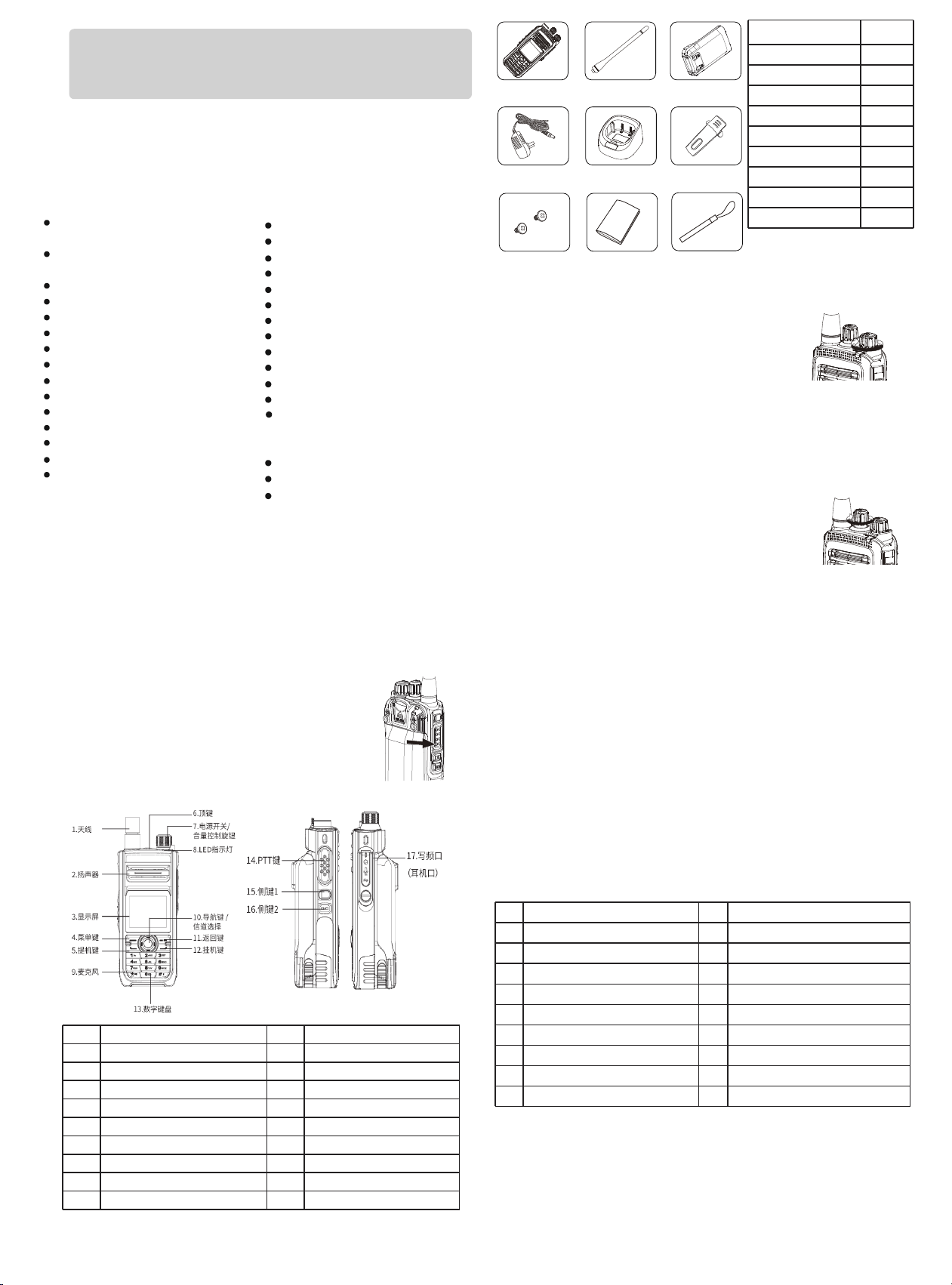
OVERVIEW
No. Items
1 Antenna
2 Speaker
3 MIC
4 LCD Display
5 MENU Key
6 Programming Key 1 (P1)
7 Channel Knob
8 Power / Volume Knob
9 LED Indicator
Notes: Users need to understand well the functions which definite in Keypad /
Side Buttons / LCD Display Icon / LED Indicator, then can maximize the
capabilities of this DMR radio .
KEYPAD
◆
Users can check the menu function by pressing [Navigation key],
after choose the f
unction, press [MENU] key to confirm or press
[Return] key back to last menu.
◆
Users can use the 3 X 4 alphabet and digital keypad to view the
function, also can input the alias, ID and message. Some character
needs to press more times.
PROGRAMMABLE BUTTONS P1 / P2 / SK1 / SK2 / SK3
These side buttons PF1/PF2 can be allocated for certain functionalities
by software. The functions and features that c
an be programmed are
listed below, you can active / deactivate the function by short press or
long press once your definite the k
ey in advanced.
Short Press – Pressing and releasing rapidly.
Long Press – Pressing and holding for the programmed duration.
Hold the radio about 2.5cm to 5cm from your mouth. It
is important that the antenna is 2.5 cm away from your
face. Press the PTT button, the red LED w
ill be
illuminated and whilst keeping it pressed, speak into
the microphone in your normal voice. And release the
PTT key to rece
ive, the green LED will illuminate.
No. Feature No. Feature
1 None 10 Squelch
2 All Alert Tones On/Off 11 Private On/Off
3 Emergency On 12 VOX On/Off
4 Emergency Off 13 Zones Selective
5 High/Low Power 14 Battery Checking
6 Monitor 15 Lone Work On/Off
7 One key Connected “1-6” 16 1750 Tone
8 Repeater/Talk Around 17 Right Key
9 Scan On/Off 18 Left Key
FUNCTIONS OPERATION INSTRUCTION
Making and Receiving Calls
Each channel can be set as Analog or Digital
mode. Press PTT to
transmit, release PTT to receive.
1. PTT Button
VFO Mode
In the main interface, the radio can switch to VFO mode by pressing [back]
key in the frequency display mode. Users can setup the frequency by
rotating the channel knob or numeric keypad.
2. Select a Zone
Zone is a channels group, the radio supports max.250 zones and each
zone support 64 channels.
07 08
05 06
Press [MENU] key enter menu page, then press [Up]/[Down] key to
access menu and select the ‘Zone’, then press MENU] key to confirm.
Turn the channel knob to select a channel under this zone.
A Private Call is a call from an individual radio to another individual
radio.
4. Receive and Respond to a Private Call
An All Call is a call from an individual radio to every radio on the
channel. It
is used to make important announcements requiring the
user’s full attention.
5. Receive an All Call
After selecting your channel, you can select a subscriber alias or ID, or
group alias or ID by using:
• The Channel Knob
• A programmed One Touch Access button
• The Contacts list
• Manually dial (by contact lists)
Making a Radio Call
1. Making a Group Call
To make a call to a group of users, your radi
o must be configured as part of
that group.
2. Making an All Call
This function allows you to transmit to all users on the channel. Your radio
must be programmed to allow you to use it.
3. Making a Group or Private Call with the One Touch Access Button
The One Touch Access feature allows you to make a Group or Private Call to
a predefined alias or ID easily. This feature can be assigned to a shor
t or long
programmable button press, or to a long numeric button press. You can
ONLY have one alias or ID assigned to a One Touch Access button. Your radio
can have multiple One Touch Access buttons programmed.
TECHNICAL SPECIFICATION
Receiver
Sensitivity (Analog)
0.35uV/-116dBm (20 dB SINAD),
0.22uV/-120dBm (typical)
Sensitivity (Digital)
0.3uV/-117.4dBm (BER 5%),
0.7uV/-110dBm (BER 1%)
Intermodulation TIA603C: 55dB ETSI: 55dB
Adjacent Channel Selectivity
TIA603C: [email protected]KHz
ETSl: 55dB@12.5KHz
Common Channel Suppression [email protected]z
Spurious Response Rejection TIA603C: 60dB ETSI: 60dB
Spurious Radiation - 57dBm@<1GHz,- 47dBm @>1GHz
Block 80dB
Rated Audio Power 1W
Audio Response +1~-3dB
Rated Audio Distortion ≤3%
Transmitter
Power Output 4W/5W/1W
FM Hum & Noise 40dB @ 12.5 kHz
Spurious Emission -36dBm<1GHz; -30dBm>1GHz
Adjacent Channel Power 60dB @ 12.5 kHz
FM Modulation 11KΦF3E @ 12.5 kHz; 16KΦF3E @ 25 kHz
4FSK Digital Modulation
12.5kHz (Data only): 7K60FXD
12.5kHz Data & Voice: 7K60FXE
Modulation Limiting
±2.5kHz @ 12.5 kHz
Idle Slot Power -57dBm
Audio Response +1~-3dB
Rated Audio Distortion ≤3%
Digital Protocol ETSI TS 102 361-1,-2,-3
Digital Vocoder AMBE+2
TM
General
Frequency Range 136-174MHz and 400-470MHz
Channels 3000
Working Voltage 7.4V Rated
Battery Capacity 2200mAh
Dimension (H*W*D) 120 x 55 x 37mm
Weight About 319g (with battery and antenna)
Display Screen 1.77 inch
Working Temperature
-25°C~+60°C
Storage Temperature
-40°C~+85°C
Frequency Spacing 12.5kHz/25KHz (Analog) 12.5kHz (Digital)
Frequency Stability
±1.0 ppm
TECHNICAL SPECIFICATION
Note: The above specifications are tested in accordance with applicable standards and
subject to change without prior notice due to the continuous development of
technology.
Emergency Alert
An emergency alert is used to indicate an emergency situation, and you can
initiate an emergency call at any time or on any page when users operate
radio, even if there is activity on the
current channel. Your radio must be
programmed for the button before use.
There are three emergency alert modes as below.
- Emergency Alert
- Emergency Alert & Calling
- Emergency Alert & Voice
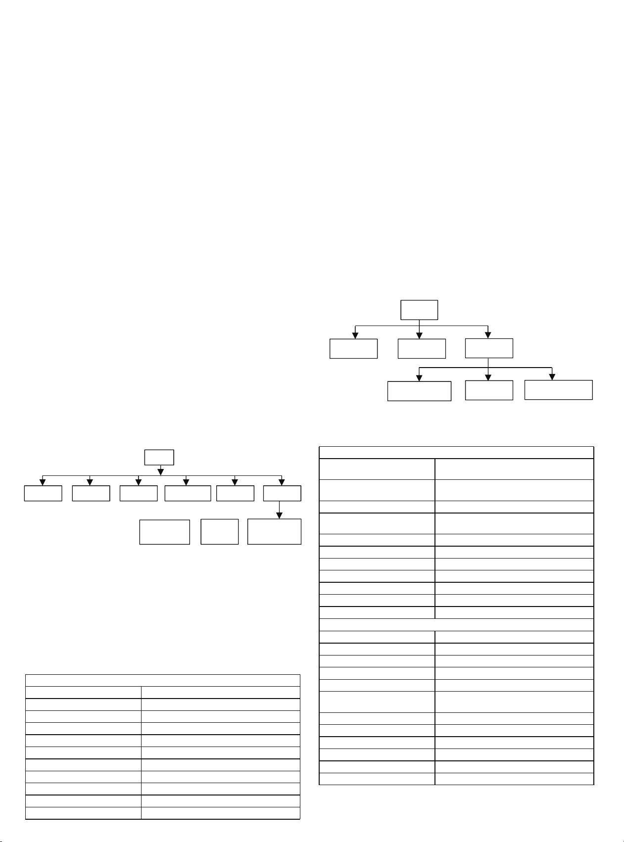
OPERATION OF MENU
Most functions of the radio can be realized through the menu. The steps of
Menu operation as below.
- Press [MENU] key enter menu page, press [Up]/[Down] key to
check items in Menu.
- Press [MENU] key
to confirm a selection or entry next page.
- Press [Back] key return to last page.
Note: After a period of inactivity, the radio will automatically exit the
menu and return to main screen (the hang time is set by the
programming software).
Menu of Analog Mode
MENU
Scan
Zone
Utilities
Radio Info
Radio Setting
Program Radio
Menu of Digital Mode
MENU
Contacts Scan Zone Messages Call log Utilities
Radio
Info
Radio
Setting
Program
Radio
To receive a call made to a group of users, your radio must be
configured as part of that group.
3. Receive and Reply a Group Call
Under this menu, users can setup the functions include “Password Lock
Features”, “Turning the Radio Tones/Alerts On or Off”, “Set Squelch Level”,
“Set Power Level”, “Turn On/Off Display Backlight”, “Turn the Introduction
Screen On or Off”, “Turn On/Off th
e VOX”, “Language”, “Turn On/Off VOX”,
“Turning the Password”, Lock On or Off”, “Changing the Password”,
“Accessing General Radio Information”, “Checking the Radio Alias and ID”,
“Checking the Firmware Version”…… and so on.
But there are some functions that can only be used on radio after they are
set in the software.
Security
You can enable or disable any radio in the system. Users can choose
the
function by MENU operation, to active “Radio Disable" or “Radio
Enable”.

FCC STATEMENT:
Any Changes or modifications not expressly approved by the party responsible for
compliance could void the user's authority to operate the equipment.
This device complies with part 15 of the FCC Rules. Operation is subject to the following
two conditions: (1) This device may not cause harmful interference, and (2) This device
must accept any interference received, including interference that may cause undesired
operation.
RF Exposure Statement:
SAR tests are conducted using standard operating positions accepted by FCC with the
device transmitting at its highest certified power level in all tested frequency bands,
although the SAR is determined at the highest certified power level, the actual SAR level of
the device while operating can be well below the maximum value. Before a new model is
an available for sale to the public, it must be tested and certified to the FCC that is does not
exceed the exposure limit established by the FCC. Tests for each product are performed in
positions and locations as required by the FCC. For body worn operation, this device has
been tested and meets the FCC RF exposure guidelines when used with and accessory
designated for this product or when used with and accessory that contains no metal. To
maintain compliance with FCC RF exposure guidelines, hold the transmitter and antenna at
least 1 inch (2.5 centimeters) from your face and speak in a normal voice, with the antenna
pointed up and away from the face.
Note: This equipment has been tested and found to comply with the limits for a Class B
digital device, pursuant to part 15 of the FCC Rules. These limits are designed to provide
reasonable protection against harmful interference in a residential installation. This
equipment generates, uses and can radiate radio frequency energy and, if not installed and
used in accordance with the instructions, may cause harmful interference to radio
communications. However, there is no guarantee that interference will not occur in a
particular installation. If this equipment does cause harmful interference to radio or
television reception, which can be determined by turning the equipment off and on, the
user is encouraged to try to correct the interference by one or more of the following
measures:
-Reorient or relocate the receiving antenna
-Increase the separation between the equipment and receiver.
-Connect the equipment into an outlet on a circuit different from that to which the receiver is
connected.
-Consult the dealer or an experienced radio/TV technician for help.
WARNING: MODIFICATION OF THIS DEVICE TO RECEIVE CELLULAR
RADIOTELEPHONE SERVICE SIGNALS IS PROHIBITED UNDER FCC RULES AND
FEDERAL LAW.