DP01
USER
MANUAL
·
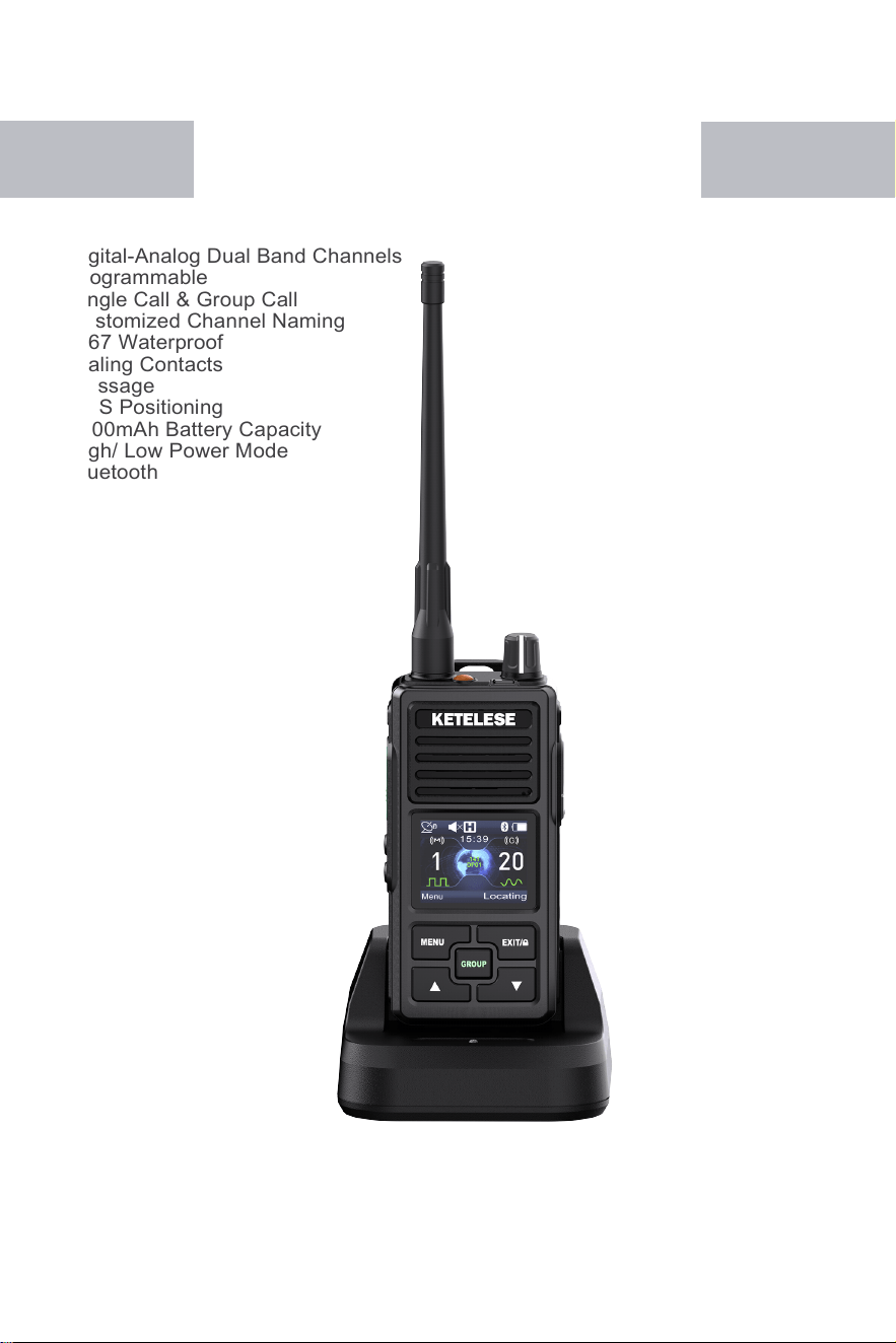
Digital-Analog Dual Band Channels
·
Programmable
·
Single Call & Group Call
·
Customized Channel Naming
·
IP67 Waterproof
·
Dialing Contacts
·
Message
·
GPS Positioning
·
2000mAh Battery Capacity
·
High/ Low Power Mode
·
Bluetooth


DP01 USER MANUAL
1.
Product
Layout
···························································
1
2.
Annotation of The Radio Home Page Icon
···················
3
3.
Accessories
List
··························································
4
4.
General Operation
·······················································
5
5.
Battery Removal/Installation ············································· 6
6.
Headset Installation ························································ 7
7.
Charging Method ···························································· 8
8.
DP01 Function and Operation Manual ································· 9
A.
Contacts Function ······················································ 9
B.
Message Function ·····················································11
C.
Call Log Function ·······················································12
D.
Scan Function ··························································13
E.
GROUP Function ······················································13
F.
Settings Function ·······················································14
G.
Positioning Function ···················································15
H.
Bluetooth Function ·····················································16
9.
Product Default Parameter Settings ···································17
10.
Extension of Battery Life ················································18
11.
User Security Information ··············································19
Catalogue
DP01 USER MANUAL
1. Product Layout
01
02
DP01 USER MANUAL
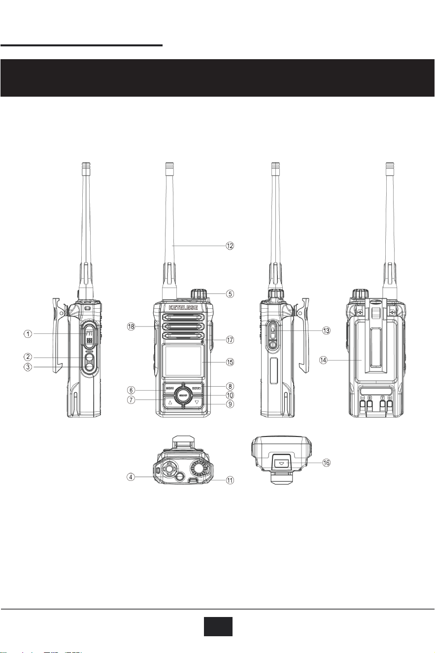
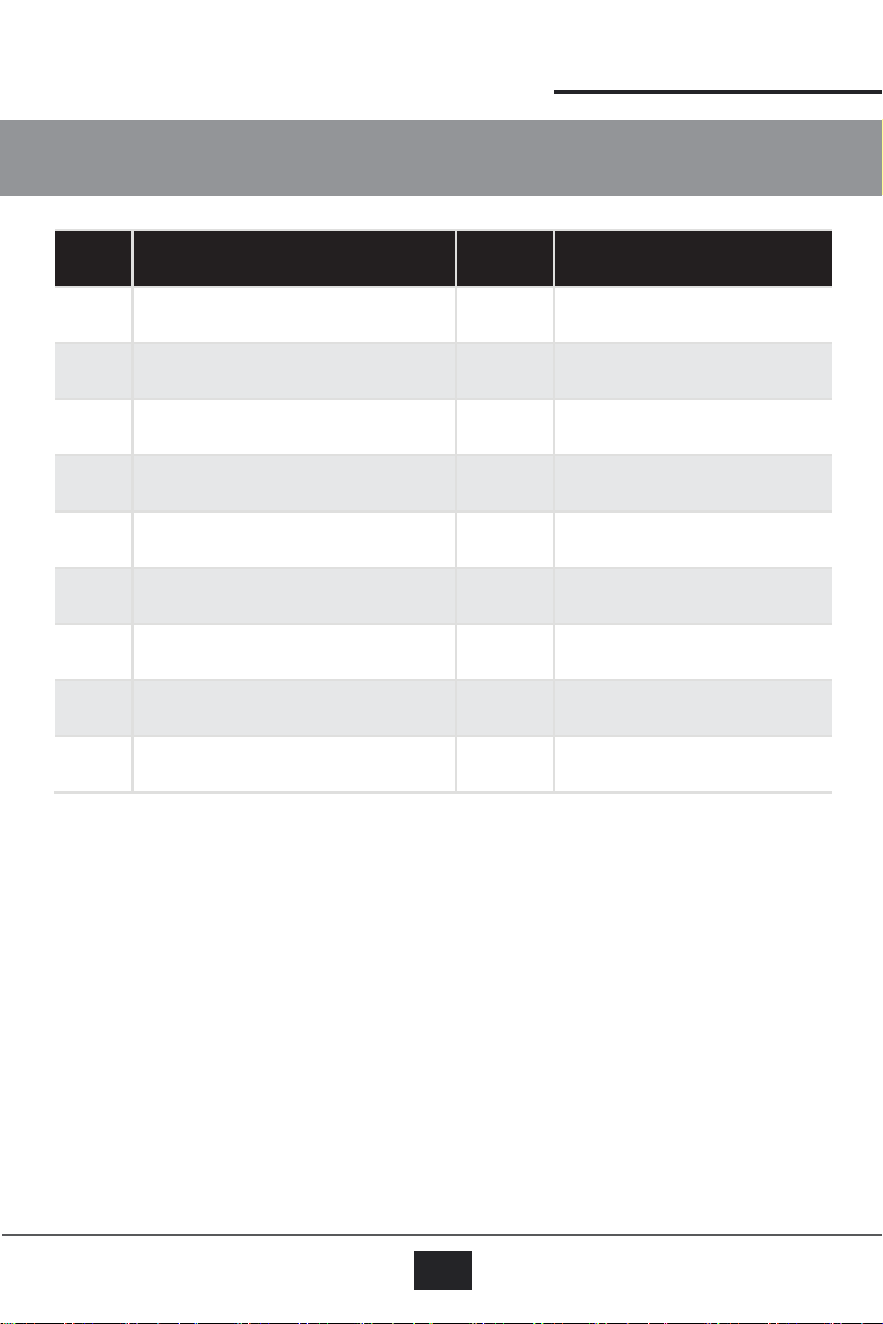
NO. Part Name NO. Part Name
1
Push-to-Talk (PTT) key
10
GROUP Key
2
Side Key 1 (SK1)
11
LED Indicator
3
Side Key 2 (SK2)
12
Antenna
4
Emergency Alarm Key
13
USB-C Jack
5
On-Off/Volume Control Knob
14
Battery
6
Menu Key
15
LCD Display
7
Up Key
16
Battery Latch
8
Back/Keyboard Lock Key
17
Microphone
9
Down Key
18
Speaker
Notes
:
·
The SK1 and the SK2 are programmable keys. Their functions can be modified through the
programming software.
·
By default, the SK1 is for monitoring function, and short press is for switching between high and
low power.
·
Long press of the SK2 is for scanning function, and short press is for turning on/off the prompt
tone.
DP01 USER MANUAL
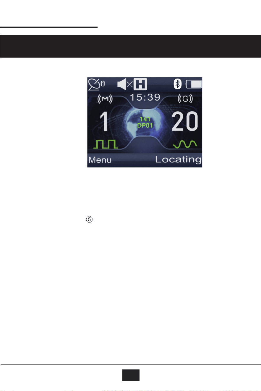
2. Annotation of The Radio Home Page Icon
03
Volume level
The current number of
satellites used by
GPS
Main channel
High model /
Low model
Battery power
Group channel
Radio ID
User Name
Digital Channel
Analog channel
Notes
:
Regarding the display of the icon, the display HIGH/LOW icons will be based on the
corresponding power selection within the radio.
04
DP01 USER MANUAL
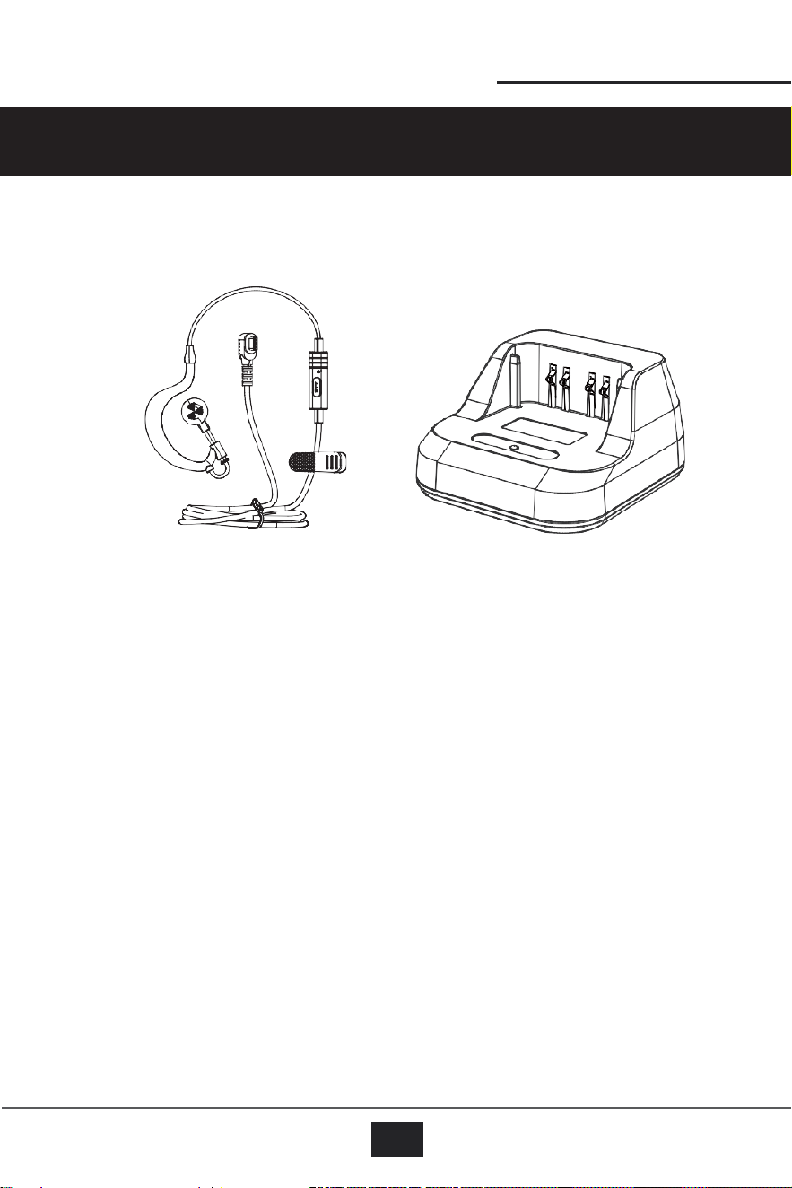
Earphone Charging base
Notes
:
To avoid risk of fire or shock, use only original DP01 power supply inside the package.
3.
Accessories List
DP01 USER MANUAL
4. General Operation
05
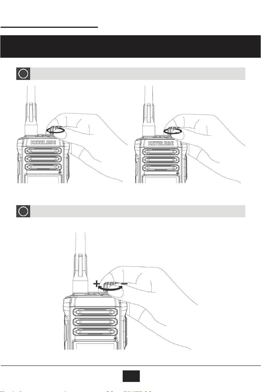
Volume Adjustment Operation
2
Turn on/off operating
1
Power on
Power off
DP01 USER MANUAL
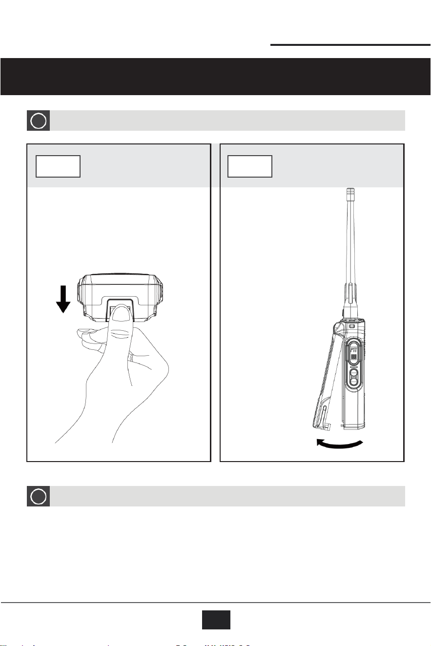
5. Battery Removal/Installation
06
Battery Installation
2
To install the battery, align it with the slot in the same direction as removal and press it back in
until you hear a "click" sound, indicating successful installation.
STEP 1
STEP 2
Locate the battery
Hold the latch
latch at the bottom of
and pull it
the device and place
outward in the
your hand on the
direction shown
latch.
in the diagram
to remove the
battery.
Battery Removal
1
DP01 USER MANUAL
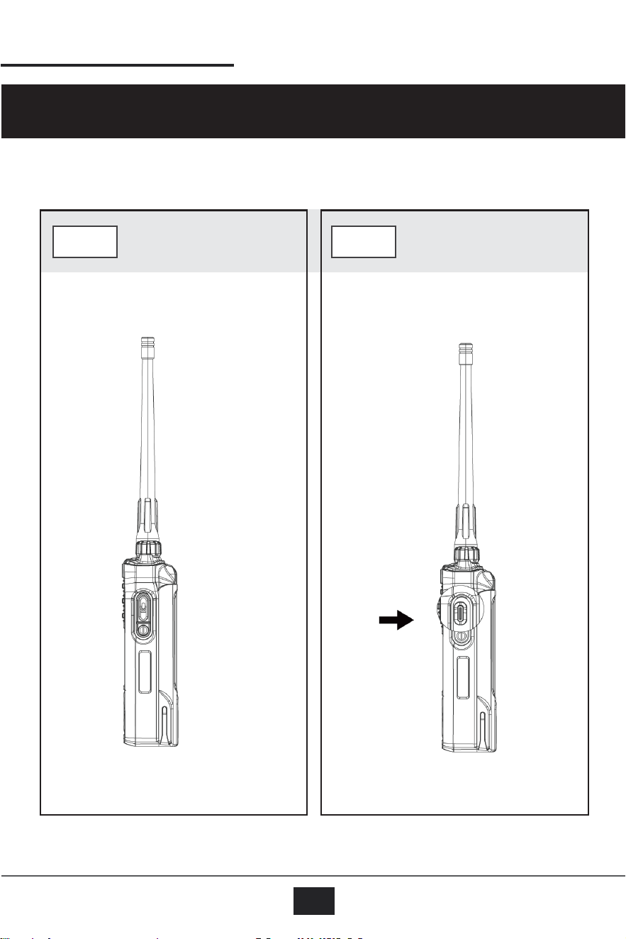
6. Headset Installation
07
STEP 1
STEP 2
Locate the silicone cover on the side of
the radio with a microphone icon.
Open the silicone cover and insert the
Type-C headset cable into the port to
complete the headset installation.
08
DP01 USER MANUAL
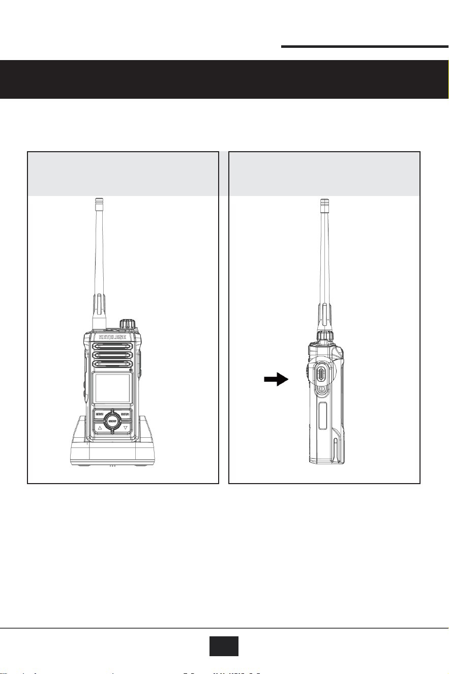
Charging with a Dock Charger
Charging with a Type-C Cable
7. Charging Method
DP01 USER MANUAL
09
A. Contacts Function Operation Instructions
The menu lists differ between Digital Mode and Simulation Mode, with certain menu items
omitted in Simulation Mode.
Nevertheless, the functionalities available in Simulation Mode remain consistent in content
and definition with those in Digital Mode, ensuring a uniform user experience.
1. Contacts (Menu → Contacts)
1.1
Default Contacts 4/200:
At the factory, four contacts are preset by default. These include the All-
Call contact, contact 1, Contact 2 and Emer-contact.
1.2
All-Call Contact:
The All-Call contact is the default transmitting contact. You can enter the All-
Call contact to view its name (“All-Call”), along with your own radio number
and its category, which is “All-Call.”
1.3
Modifying the Tx Contact:
You may change the Tx contact to a specifically designated Contact. In this
case, PTT communication will be limited to a two-party conversation, and no
one else will be able to listen or participate.
1.4
Deleting Unused Contacts:
You may also delete any specific contacts that are no longer needed.
1.5
Emer-contact:
1.5.1
The emergency alarm contact ID is preset at the factory to 999999
(compatible with radios of the same model).
Notes
: If changes are required, the ID must be modified using the
programming software.
8. DP01 Function and Operation Manual
10
DP01 USER MANUAL
1.5.2
Emergency Alarm Operation
• Press the orange emergency alarm key (short press) on the top of the
radio to trigger the digital emergency alarm system when operating on a
digital channel.
•By default, the radio will transmit an emergency alarm signal and sound an
alert tone. Once the pop-up confirms successful transmission, the radio
automatically transmits the emergency signal for 10 seconds, then stops for
10 seconds in standby mode. This cycle repeats up to 5 times.
•After 5 automatic transmissions, the radio remains in Emergency Standby
Mode with a “Emergency Call” pop-up notification.
•The emergency alarm state will not exit automatically. To exit, press and
hold the orange emergency alarm key.
2. Manual Dialing
2.1
Direct Calling:
Enter Manual Dialing mode to input a contact's extension number for a direct
call.
2.2
Extension Number Format:
The maximum length of the radio ID is to 8 digits, but it should not exceed
16777215.
2.3
Editing the Number:
A cursor appears beneath the digits. Use the
▲
and▼ arrow keys to move the
"-" cursor to the digit you wish to modify. When the "-" cursor is positioned
under the desired digit, press the MENU key. The “-"cursor will start blinking,
indicating that the digit is in edit mode.
Each press of the adjustment key will cycle the digit sequentially from 0 to 9.
Once you have selected the desired digit, press the MENU key again. The "-"
cursor will stop blinking, confirming that the digit has been set.
Finally, just press the PTT button to call out.
3. Creating a New Contact
3.1
Editing the Number
3.1.1 You can set an 8-digit extension number.
3.1.2 A“-"cursor appears beneath the digits. Use the ▲and
▼
arrow keys to
move the cursor to the digit you want to modify. When the“-”is positioned under
the desired digit, press the MENU key. The cursor will start blinking, and each
press of the adjustment key will cycle the digit sequentially from 0 to 9. Once
you have selected the correct digit, press the MENU key again; the “ - ”will stop
blinking, indicating that the digit is set. Then, press the Return key to go back to
the Contacts menu.
DP01 USER MANUAL
11
B. Message Function Operation Instructions
Notes
: The first digit can only be “0”or”1”.
3.2
Editing the Name
3.2.1 When you see the“-”cursor, press the MENU key. The cursor will begin
blinking, and each press of the adjustment key will cycle through the letters A,
B, C, … up to Z. Once you have chosen the desired letter, press the MENU key
to confirm; the cursor will stop blinking, indicating that the letter is set.
3.2.2 Press the and key again to move the cursor to the next letter position.
Repeat the process: press MENU, cycle through the letters until you find the
one you want, then press MENU to lock it in. Continue until you have entered
the full name.
3.3
Saving the Contact
Once you have finished setting up the new contact, press the Save key. A
“Save Successful” message will be displayed, and the contact’s name and
number will be added to the Contact list.
4. Deleting a Contact
4.1
In the Contacts list, select the contact you want to delete.
4.2
Once selected, you will see the option “Delete Contact” in the list. Select this option
to delete the contact.
1. Message (Menu → Message)
All messages can only receive and send preset content from the quick file. To
customize SMS content, you must preset it using the configuration software.
1.1 Inbox
1.
1.1 Inbox List (0/60):
A maximum of 60 messages can be stored. Older messages will be overwritten
by the latest ones. Press the MENU button once to view a message; messages
are displayed from the most recent to the oldest.
1.1.2 Viewing or Deleting Messages:
Press the Return key, then use the Up/Down keys to choose whether to view
the SMS content or delete it.
1.1.3 Delete All Messages:
You can also delete all messages in the Inbox.

DP01 USER MANUAL
12
C. Call Log Function Operation Instructions
1. Dialed Calls (Menu → Call Log)
1.2 Quick Text
1.2.1 Viewing Quick Text
Press the MENU button to view all preset quick text messages.
1.2.2 Sending Quick Text
Use the Up/Down keys to select the content you wish to send, then press the
MENU button to choose the recipient. After selecting the recipient, press the
MENU button again to send the message successfully.
1.1 Dialed Call Log (0/60):
The Dialed Call List and the Received Call List share a total capacity of 60
records. The factory default display is 0/60.
Older entries will be overwritten by newer records. Press the MENU key to view
the contact's name, number, and time of call.
Notes
: Only calls from contacts in the call list will be recorded.
1.2 Delete All Records:
You can also delete all dialed call records.
2. Received Calls
2.1 Received Call Log (0/60):
The Dialed Call List and the Received Call List share a total capacity of 60
records. The factory default display is 0/60.
Older entries will be overwritten by newer records. Press the MENU key to view
the contact's name, number, and time of call.
Notes
: Only calls from contacts in the call list will be recorded.
2.2 Delete All Records:
You can also delete all received call records.
DP01 USER MANUAL
13
D. Scan Function Operation Instructions
E. GROUP Function Operation Instructions
(Menu → Scan)
1. Scan Switch:
Select to enable or disable the scanning function.
2. Scan List:
Choose a scan list to specify the channel range for scanning.
Further Explanation: Custom SCAN Frequency Range
If you have modified the scan list using the programming software, select the
desired scan range from the scan list.
The frequency range supported by the radio is UHF 406.1MHz-470MHz.
Notes
: The default factory setting scans all channels, with 10 analog channels
and 10 digital channels preset.
You can download our programming software through the website:
www.DP01-radios.com.
Please don't hesitate to reach out to DP01 Team:
sanconmarketing2@outlook.com if you need any tech supports.
(Menu → GROUP)
1. Dual-Channel Monitoring:
This function enables the radio to monitor two channels simultaneously. One
channel is used for PTT (Push-To-Talk) communications, and the other is
accessed via the "GROUP" button. These channels are referred to as the PTT
channel and the Group channel.
2. Emergency Communications:
When the GROUP channel is set to the same frequency as the PTT channel, it
can be used for emergency communications. In this configuration, even if the
primary channel is on a different frequency, the GROUP channel remains
available for emergency use.
3. Simultaneous Dual-Channel Operation:
When the GROUP channel is set to a different frequency, the radio can quickly
operate on two channels simultaneously, enhancing communication flexibility.

DP01 USER MANUAL
14
F. Settings Function Operation Instructions
4. Disabling the GROUP Function:
When the GROUP channel is set to "None," this function is disabled. In this state,
pressing the GROUP button will neither transmit nor receive any calls.
(Menu → Settings → Radio Settings)
1. Radio Settings
1.1 Transmission(Tx) Power Level:
Switch between high power and low power transmission modes.
1.2 Backlight:
Choose the backlight duration: options include 15, 30, 45, or 60 seconds.
1.3 Brightness:
Adjust the backlight brightness across 9 levels by press
▲
and
▼
key.
1.4 Prompt Tone:
Enable or disable audio cues for receiving, transmitting, and key presses.
1.5 Squelch Level:
Adjust the level of noise suppression. The higher the level, the better the noise
suppression effect.
1.6 Language:
Switch the device language. Currently, the available options are Chinese and
English.
1.7 Voice Operated Transmitter(VOX):
Adjust the IVOX sensitivity across 5 levels, or disable the IVOX function entirely.
1.8 T
ime Zone:
Select the correct UTC time based on your country or region.
1.9 Date&Time:
Modify date and time.
Notes
: The date and time can only be modified when GPS is turned off. If GPS is
enabled, the current date and time will automatically be set according to the GPS
location.
DP01 USER MANUAL
15
G. Positioning Function Operation Instructions
1.10 Lone Worker:
This feature is designed to prevent a person from losing contact when working
alone.
Once activated, if the radio is not operated (such as pressing a button or
transmitting) within the set time(The default time is 10 minutes and can be
modified through the programming software), it will first emit a prompt tone to
alert the user.
If no operation is performed after the prompt tone ends, the walkie-talkie will
automatically trigger the emergency alarm function and send out an emergency
alarm signal to Emer-contact.
2. Device Information (Menu → Settings → Device Information)
View relevant details about your device, including:
Notes
ID
:
Extension Number
Name: User Name
Freq
:
Frequency
DMR
:
DMR Version
HW
:
Hardware Version
SW
:
Software Version
D
:
Programming Date
(Menu → Positioning)
1. Location Share
This radio is equipped with a GPS positioning chip and antenna, allowing it to send
GPS location data during communication.
DP01 USER MANUAL
16
H. Bluetooth Function Operation Instructions
1.1 Follow TX Operation:
Each time a transmission is made, the current location information will be shared
with the designated contact.
1.2 Periodically:
You can set the radio to automatically send the current location to the designated
contact every 30 minutes..
1.3 Distance Exceeded:
You can set the radio to automatically send the current location to the designated
contact each time the distance from the contact increases by 1,000 meters.
Notes
: The transmit contact can be set under the “Contacts” menu. By default, the unit
is configured to send to all contacts.
2. Location Display
Displays the device's current time, longitude, latitude, altitude, and heading
angle.
Notes: Ensure that the correct UTC time zone is set in the radio settings; otherwise,
the displayed time may be inaccurate.
3. Azimuth Map Display
This feature provides a visual representation of the device’s orientation relative to
the North and South Poles, functioning as a compass.
4. Azimuth Calibration
To calibrate the position coordinates, slowly rotate the device horizontally twice.
The system will automatically adjust the positioning.
(Menu → Bluetooth)
This feature allows the radio to connect wirelessly to compatible Bluetooth audio
devices, such as headsets or earpieces, for hands-free communication. Before use,
please ensure your Bluetooth device is set to pairing mode.
1. On/Off
Select this option to enable or disable the radio's Bluetooth functionality. When
enabled, a Bluetooth icon will typically appear on the display, and the radio can
DP01 USER MANUAL
17
connect to other devices. To conserve battery, it is recommended to turn Bluetooth
off when not in use.
2. Saved Device
This menu displays a list of Bluetooth devices that have been previously paired with
the radio.
Connecting: Use the Up/Down keys to navigate the list and highlight a saved device.
Press the MENU key to initiate a connection.
Managing: Within this menu, you may also have an option to delete a device you no
longer wish to connect to automatically.
3. Seach
This option scans for new, discoverable Bluetooth devices nearby.
Select "Search" to begin scanning. A list of available devices will appear on the
screen.
Use the Up/Down keys to select the device you wish to connect to from the list.
Press the MENU key to start the pairing process. You may need to confirm a
prompt on both the radio and your Bluetooth device to complete the pairing. Once
paired, the device will be added to your "Saved Devices" list for future connections.
4. Bluetooth PTT
This setting enables the Push-to-Talk function through a connected Bluetooth
accessory.
On: W
hen this feature is turned On, you can press the designated PTT button on
your connected Bluetooth device to transmit audio from the radio.
Off: When turned Off, the PTT button on the accessory will be disabled, and you
must use the PTT button on the side of the radio to transmit.
Note
: The Bluetooth PTT feature requires a compatible accessory that supports this
specific function. Not all Bluetooth audio devices have a PTT button or the required
profile.
ON: When the setting is turned on, to have the radio start or stop the transmitting operation, besides pressing
the buttons on the radio, you also can touch or press the designated button on the connected Bluetooth device.
This setting enables the Push-to-Talk function of the radio DP01 through a connected Bluetooth
accessory such as Bluetooth buds
OFF: When the setting is turned off, to have the radio start or stop the transmitting operation, only can you
press the buttons on the radio.
DP01 USER MANUAL
18
CH.
No.
Frequency
/MHz
Mode
Sub
-
Cod
e
or
CC
Channel
Spacing
/KHz
CH.
No.
Frequency
/MHz
Mode
Sub-
Code
or
CC
Chann
el
Spaci
ng
/KHz
1
464
.
5000
Digital
1
12
.
5
11
464
.
5000
Analog
67Hz
12
.
5
2
464
.
5500
Digital
1
12
.
5
12
464
.
5500
Analog
67Hz
12
.
5
3
467
.
9250
Digital
1
12
.
5
13
467
.
9250
Analog
67Hz
12
.
5
4
461
.
0375
Digital
1
12
.
5
14
461
.
0375
Analog
67Hz
12
.
5
5
461
.
3625
Digital
1
12
.
5
15
461
.
3625
Analog
67Hz
12
.
5
6
466
.
0375
Digital
1
12
.
5
16
466
.
0375
Analog
67Hz
12
.
5
7
451
.
1875
Digital
1
12
.
5
17
451
.
1875
Analog
67Hz
12
.
5
8
452
.
3125
Digital
1
12
.
5
18
452
.
3125
Analog
67Hz
12
.
5
9
456
.
1875
Digital
1
12
.
5
19
456
.
1875
Analog
67Hz
12
.
5
10
457
.
3125
Digital
1
12
.
5
20
457
.
3125
Analog
67Hz
12
.
5
In the factory default settings, 20 channels are preconfigured.
The first 10 channels are digital channels, and the remaining 10 channels
are analog channels.
9. Product Default Parameter Settings
DP01 USER MANUAL
19
The performance of the battery will be reduced when the temperature drops below 0
℃
.
In cold weather, it is advised to spare another battery for emergency. Please do not
dispose the cold batteries that can not work at low temperature but may be usable at
room temperature
lt may affect the normal use or charge of the battery, if it is covered with dust. Please
clean the battery with dry cloth before loading or charging it
Knowledge about Battery Storage
Since the battery will self-discharge, please do charge it fully before putting it aside so
as to prevent damages caused by over discharge.
Please take out the battery after storage for some time to fill it, in order to avoid the
reduction of the battery capacity resulting from over discharge. lt is proposed for
lithiumion /lithium-polymer batteries to be filed in every 6 months of storage.
Please pay attention to the humidity of the battery storage environment. Batteries are
supposed to be stored in the environment of room tempera- ture, cool and dry air, to
reduce the self-discharge.
10. Extension of Battery Life
DP01 USER MANUAL
11. User Security Information
19
Handheld Transceiver Safety Guidelines and Instruction
Warning:
Please read the manual carefully before using. lt contains the important safety using
operation instruction, and RF energy and control information contributing to meet the
RF radiation limitation requirement of national and international standards.
information provided in this manual may replace the general safety information of the
editions before.
To control the transceiver radiation, ensure to meet the general or non-con- trolled
environment radiation limitation standard please operate following below procedures.
Press PTT key when talking: and release PTT key when receiving.
Because measured RF energy radiation will be generated when transmitting, so
transmitting time should not exceed 50% of the using time.
Place the transceiver vertically on the front, make sure the microphone (and other
parts including the antenna) is no less than 1 to 2inches (i.e. 2.5 to 5cm) away from
your lips when transmitting signals. It is very important to keep the correct distance
from the transceiver, since the farther away the less radiation.
If you carry the portable transceiver around your body, please put into DP01 specially
designed fixture, leather, box or other annex. Only use the certified and provision
antenna, battery and accessories or other alternatives by DP01. If not, the body by
radiation will be out of range of general or non-controlled environment RF radiation
limitation that required by Radio Authority. Ministry of Information industry.
If you do not use any accessories, not place the transceiver on the front specified
location, please make sure that it is no less than.
1 inch (about 2.5cm) away from your body when transmitting signals. It is very
important to keep the correct distance from the transceiver, since the farther the less
radiation.
Handheld transceiver product safety and RF radiation

DP01 USER MANUAL
20
Attention:
This radio complies with IEEE and ICNIRP exposure limits for Occupational /
Controlled RF exposure environment at operating duty factors of up to 50% and is
authorized by the FCC for Occupational / Controlled use only. An appropriate warning
label is affixed to all units. In order to comply with RF exposure requirements, a
minimum distance of 2.5 cm must be maintained when held-to-face, and body-worn
operations are restricted to the approved original accessories (belt clip), a minimum
distance of 0 cm. Do not use this device when antenna shows obvious damages.
This product is compliance to FCC RF Exposure requirements and refers to FCC
website https://apps.fcc.gov/oetcf/eas/reports/GenericSearch.cfm search for FCC ID:
2A4CJ-DP01 to gain further information include SAR Values.
Notes: This equipment has been tested and found to comply with the limits for a
Class B digital device, pursuant to part 15 of the FCC Rules. These limits are
designed to provide reasonable protection against harmful interference in a
residential installation. This equipment generates, uses and can radiate radio
frequency energy and, if not installed and used in accordance with the instructions,
may cause harmful interference to radio communications. How- ever, there is no
guarantee that interference will not occur in a particular installation. If this equipment
does cause harmful interference to radio or television reception, which can be
determined by turning the equipment off and on, the user is encouraged to try to
correct the interference by one or more of the following measures:
Reorient or relocate the receiving antenna.
Increase the separation between the equipment and receiver.
-Connect the equipment into an outlet on a circuit different from that to which the
receiver is connected.
-Consult the dealer or an experienced radio/TV technician for help.
Changes or modifications not expressly approved by the party responsible for
compliance could void the user's authority to operate the equipment.
This device complies with part 15 of the FCC Rules. Operation is subject to the
condition that this device does not cause harmful interference.