W A T E R C O NDI T I O N E R
ELECTRONIC
DEMAND
ELECTRONIC CONTROL BOARD (PWA) REPLACEMENT
7328108 (Rev. A 1/24/11)
10. Press the UP (
) or DOWN (–) buttons to set the present time.
Up moves the display ahead; down sets the time back. Be sure
AM or PM is correct.
NOTE: Press buttons and quickly release to slowly advance the
display. Hold the buttons down for fast advance.
11. Press the SELECT button a few times, until the time appears on
the display, but is not flashing.
12. For information about programming additional features of the
softener, consult your owner’s manual.
13. If the valve is not in Service position, press the RECHARGE button
and hold for 3 seconds to start a recharge cycle. The display will
flash “RECHARGE NOW.” In about 2 hours the recharge cycle will
be complete and the valve and electronic control board will be
properly oriented together.
NOTE: To save time, use the manual advance procedures to properly
time and check operation. See service information in the
manual.
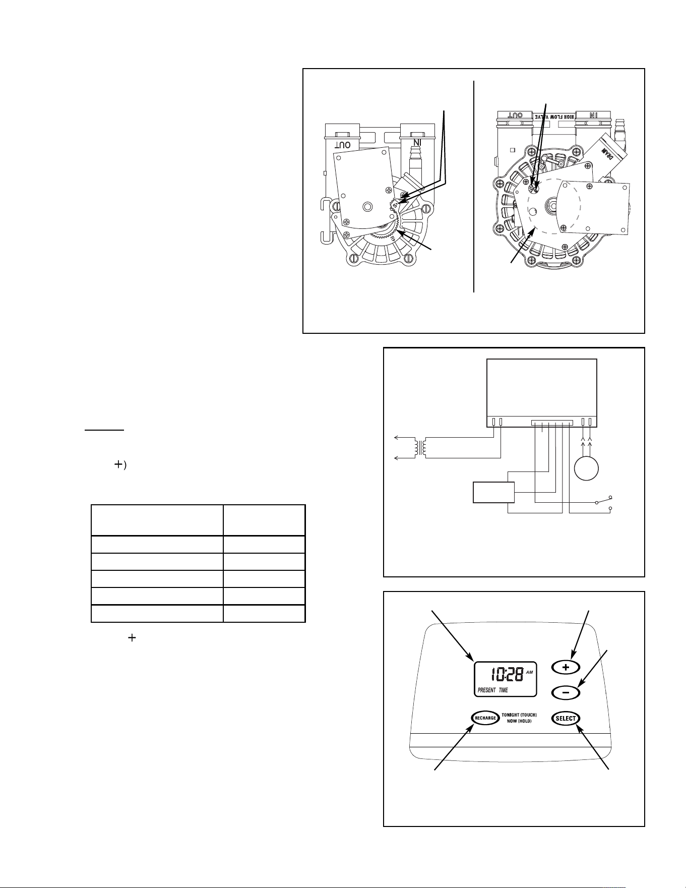
Figure 2
Trans-
former
Back of Electronic
Control Board
Valve
Motor
Turbine
Sensor
Valve Position
Switch
Model Number
Model Code
to select
GS 6130 or EP 6130 E6130
GS 6225 or EP 6225 E6225
GS 6245 or EP 6245 E6245
GS 6260 or EP 6260 E6260
EP 6230 E6230
Figure 3
RECHARGE
button
SELECT
button
Display
DOWN
button
UP button
6. Reconnect the wiring to the new board (See Figure 2).
7. Plug the transformer into the electrical outlet. A model code and a
test number shows in the display for a few seconds.
8. If the correct model code for your softener did not display when the
transformer was first plugged in, set the model code as follows:
Press and hold the SELECT button until “000 - -” shows. Then
press the SELECT button again until a model code (example:
“E6130”) shows.
9. Use the UP (
) or DOWN (–) buttons to set the correct model code
for your softener (see table below). Then press the SELECT button
to set, and change to the flashing “PRESENT TIME” display.
Figure 1
IMPORTANT: BE SURE THE VALVE CAM INDI-
CATES “SERVICE” POSITION (See Figure 1)
WHEN REPLACING THE ELECTRONIC
CONTROL BOARD (PWA), TO ASSURE BOTH
VALVE AND PWA ARE ORIENTED, OR TIMED,
TO THE SAME CYCLE. If the valve is not in
Service position, see step 13 below.
NOTE: When installing the electronic control board
(PWA) on the faceplate, use care not to twist the
circuit board, or force it onto the mounting pegs.
Twisting could damage the printed circuits, or break
the display glass.
1. Unplug the water softener’s transformer from elec-
trical power
2. Remove the faceplate cover to expose the valve.
3. Unplug the wiring connections from the back of
the old Electronic Control Board (See Figure 2).
4. Carefully remove the old board by unsnapping it
from its retainer tabs.
5. Carefully snap the new Electronic Control Board
into the retainer tabs.
1” Valve
MOTOR
CAM
Position markers
(valve in service)
Position markers
(valve in service)
CAM
MOTOR
3/4” Valve