Lightning and ESD Protection
Before mounting the AP, consider Lightning and ESD Protection to ensure
safety.
Proper grounding is extremely important for outdoor devices. By using a
shielded CAT5e (or above) cable for connection, you can reduce the
damage of ESD attacks.
Hardware Installation
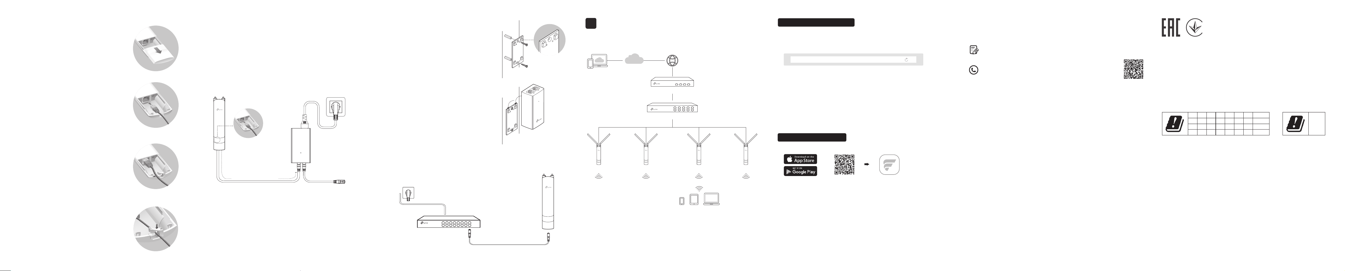
Mount the AP
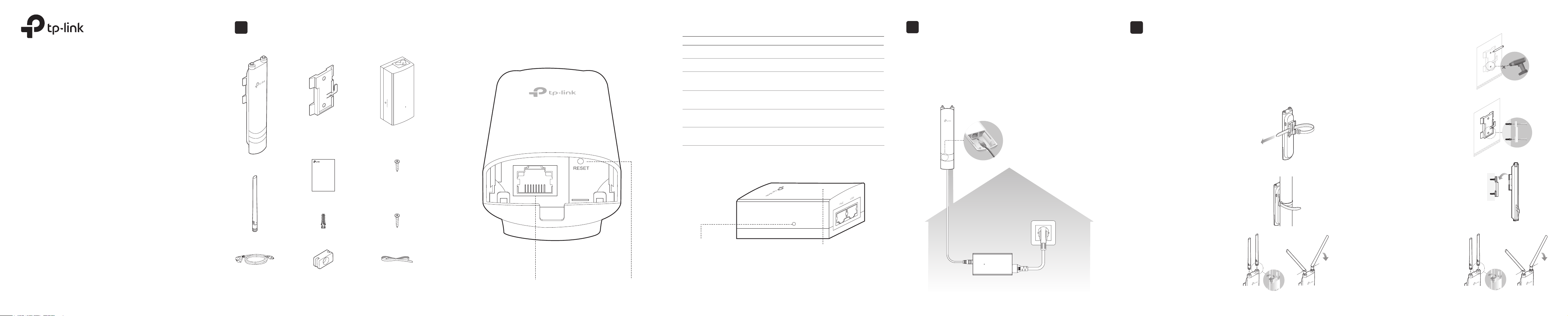
The AP can be pole-mounted or wall-mounted. Follow the steps below for
the appropriate installation.
Option 1: Pole Mounting
Option 2: Wall Mounting
Step 1:
Place the mounting bracket (for AP) in
the right position. Mark two positions
for the screw holes.
Drill two holes for the screws at the
marked positions.
Step 2:
Insert the plastic wall anchors into the
holes.
Align the bracket (for AP) to the plastic
wall anchors and drive the self-tapping
screws into the anchors through the
bracket (for AP).
Step 3:
Align the mounting tabs on the back of
the AP with the slot of the mounting
bracket (for AP).
Push and slide the AP downward until
it locks into place.
Φ 7.6 mm (19/64 in)
Lead the end of the pole mounting strap
through the back of the AP.
Step 1:
Position the AP and wrap the pole
mounting strap around the pole.
Feed the end through the screw-block
and tighten the strap until the AP is
secure.
Step 2:
3
AP
Grounded PoE Adapter
Shielded CAT5e (or above)
Cable
Grounded 3-wire
Power Outlet
45°
45°
Connect the antennas to the AP. For
optimal Wi-Fi performance, adjust the
direction of the antennas.
It is recommended to position the
antennas at 45-degree angles.
Step 3:
45°
Step 4:
Connect the antennas to the AP. For
optimal Wi-Fi performance, adjust the
direction of the antennas.
It is recommended to position the
antennas at 45-degree angles.
2
45°
Indoor/Outdoor Access Point
Note: Festa F52-Outdoor is used as an example throughout the Guide. Images
may dier from your actual product.
©2024 TP-Link 7106511102 REV1.0.0
Quick Installation Guide
Overview
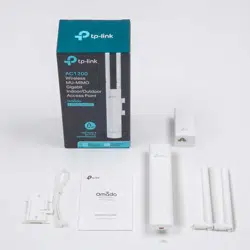
Package Contents
Panel Layout
Power LED:
On: Power on
Off: Power off
Note: Festa F52-Outdoor does not support the Remote Reset feature.
Passive PoE Adapter
Remote Reset:
Press and hold for about 8 seconds until the LED
is quickly flashing yellow then green. The AP will
restore to factory default settings.
LED Status
Indication
Solid green
The device is initializing or working properly.
Flashing yellow
System errors. RAM, Flash, Ethernet, WLAN or
rmware may be malfunctioning.
Flashing yellow, green
Firmware update is in progress. Do not disconnect
or power o the device.
Quickly ashing yellow, green
The device is being reset to its factory default
settings.
Flashes green twice
Initialization is completed.
SYS LED Explanation
Flashing green slowly
(Only for Festa F52-Outdoor)
The device is in an isolated state.
1
RESETShielded Ethernet
Port LAN
Passive PoE Adapter
(Mounting Bracket Included)
Power Cord
Plastic Wall Anchors Self-tapping Screws
AP
Antennas
Mounting Bracket
(for AP)
Installation Guide
Pole Mounting StrapWaterproof Rubber
Insert
Self-tapping Screws
(for Passive PoE Adapter)
Indoor/Outdoor Access Point
Note: Festa F52-Outdoor is used as an example throughout the Guide. Images may
dier from your actual product.
©2024 TP-Link 7106511102 REV1.0.0
Quick Installation Guide
Note: Accessories may vary by product.
Connect Cables
Firmly grasp the rear of the interface
cover and pull it downward.
Step 1:
Use an adequate Ethernet cable to
connect the LAN port. The length of
cable is up to 100 m for steady power
supply. Shielded CAT5e (or above) cable
is recommended.
Step 2:
Step 3:
Attach the waterproof rubber insert to the
groove at the underside of the device for
waterproong. Move the Ethernet cable to
the hole of the waterproof rubber insert.
Flatten the waterproof rubber insert until
it gets parallel to the device. Replace the
cover until it rmly locks into place.
Step 4:
Option 2: Via PoE Switch
PoE Switch
Note: Festa F41-Outdoor does not support this power option.
Connect an Ethernet cable from the PoE switch to the Ethernet port.
Power On
The AP can be powered via the passive PoE adapter or a PSE device (such
as a PoE switch) which complies with Power Source Class 2 (PS2) or Limited
Power Source (LPS) of IEC 62368-1.
Connect the AP to a Power over Ethernet (PoE) adapter as follows:
Option 1: Via Passive PoE Adapter
Connecting the PoE Adapter
PoE LAN
Ethernet cable
length up to 100 m
Mounting the PoE Adapter (Optional)
Note: To ensure the passive PoE adapter is attached most securely, it is
recommended to install the adapter with the Ethernet port facing upward.
Step 1:
Remove the mounting bracket from the
passive PoE Adapter.
Drill two holes on the wall and insert the
plastic wall anchors into the holes.
Secure the mounting bracket to the wall.
Make sure the shoulders at the corners
of the mounting bracket are on the
outside and pointing upward.
Step 2:
Attach the passive PoE adapter to the
mounting bracket (for PoE Adapter)
by sliding the adapter in the direction
of the arrows until it locks into place.
You can congure and manage Festa APs via the Festa Cloud-Based
Controller.
Option 1: Via Web Browser
Switch
Router / Gateway
Festa Cloud
Clients
AP AP AP AP
Option 2: Via Festa App
1. Make sure that your management device can access the internet.
2. Launch a web browser and enter https://festa.tplinkcloud.com in the
address bar. Log in with your TP-Link ID.
3. Click + Add Controller, then you will see you have successfully registered
for a Cloud-Based Controller and the controller has been added to the
controller list.
4. Click Set Up Now, click Config New Setup, and follow the step-by-step
instructions to complete the configuration wizard of the controller.
5. On the controller’s management page, go to Devices, click + Add
Devices, and follow the step-by-step instructions to adopt Festa devices.
Now you can configure and manage Festa devices on the controller.
https://festa.tplinkcloud.com
1. Download and install the Festa App from App Store or Google Play.
2. Launch the Festa App and log in with your TP-Link ID.
3. Tap + on the upper right corner, then you will see you have successfully
registered for a Cloud-Based Controller and the controller has been added
to the controller list.
4. Tap Confirm, tap Let’s Get Started, and follow the step-by-step
instructions to complete the conguration wizard of the controller.
5. On the controller’s management page, go to Devices, click + on the upper
right corner, and follow the step-by-step instructions to adopt Festa
devices.
Now you can configure and manage Festa devices via the Festa App.
Scan for Festa App Festa App
or
For technical support, the user guide and other information,
please visit https://www.tp-link.com/support/?type=smb, or simply
scan the QR code.
To ask questions, find answers, and communicate with TP-Link users
or engineers, please visit https://community.tp-link.com/business to
join TP-Link Community.
For detailed configurations, refer to the User Guide of the controller. The
guide can be found on the download center of our official website:
https://www.tp-link.com/support/download/?type=smb.
AT
EE
IS
NO PL PT RO SE SI SK UK(NI)
IT LI LT LU LV MT NL
EL ES FI FR HR HU IE
BE BG CH CY CZ DE DK
UK
Attention: In EU member states, EFTA countries and Northern Ireland,
the operation in the frequency range 5150MHz-5350MHz is only
permitted indoors.
Attention: In Great Britain, the operation in the frequency range
5150MHz - 5350MHz is only permitted indoors.
For Festa Controller, go to the Devices page and select the desired AP
to specify the channel.
For web browser, go to Wireless > Wireless Settings to specify the
channel.
Software Conguration
4
Safety Information
• Keep the device away from re or hot environments. DO NOT immerse in
water or any other liquid.
• Do not attempt to disassemble, repair, or modify the device. If you need
service, please contact us.
• Do not use the device where wireless devices are not allowed.
• Do not use any other chargers than those recommended.
• Adapter shall be installed near the equipment and shall be easily
accessible.
• Use only power supplies which are provided by manufacturer and in the
original packing of this product. If you have any questions, please don't
hesitate to contact us.
• Adapter should be used indoors where the ambient temperature is lower
than or equal to 40℃.
• The plug on the power supply cord is used as the disconnect device, the
socket-outlet shall be easily accessible.
TP-Link hereby declares that the device is in compliance with the essential
requirements and other relevant provisions of directives 2014/53/EU, 2009/125/EC,
2011/65/EU and (EU)2015/863.
The original EU Declaration of Conformity may be found at
https://www.tp-link.com/en/support/ce/
TP-Link hereby declares that the device is in compliance with the essential
requirements and other relevant provisions of the Radio Equipment Regulations 2017.
The original UK Declaration of Conformity may be found at
https://www.tp-link.com/support/ukca/