User Manual
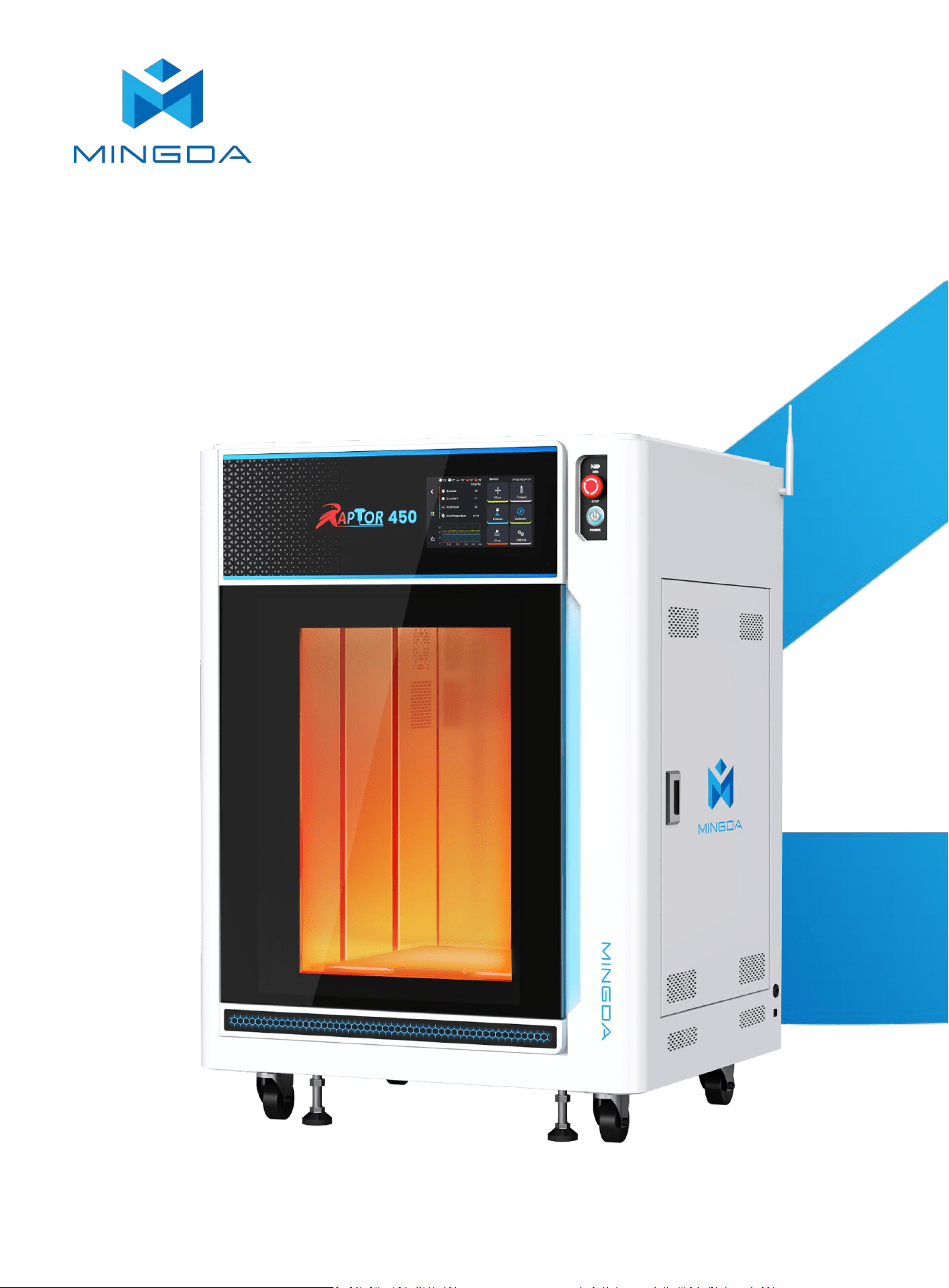
[Raptor 450 3D Printer]
Shenzhen MINGDA Technology Co.,Ltd
V2.0
*Please read this guide carefully before using this printer

Thank you for choosing MINGDA Technology's products!
For the best experience, please read this user manual carefully and follow the
instructions to operate the printer. If you encounter any issues with the printer,
please contact us using the contact information provided at the end of this user
manual. Our team is always ready to provide you with high-quality service.
1. Please do not place the printer in environments with significant vibrations or instability,
as machine shaking can affect the print quality.
2. Avoid touching the nozzle and heated bed while the printer is in operation to prevent
potential burns from high temperatures, resulting in personal injury.
3. Refrain from moving the device during the printing process to prevent accidents and
injuries.
4. Do not dismantle the equipment or alter circuit settings without authorization.
5. Avoid using the device in high-temperature or humid environments to prevent
compromising device performance or creating safety hazards.
6. In case of an emergency, immediately cease using the device and power it off.
Cautionary Notes

Contents
1 Overview …………………………………………………………………………………………………………………..........
2 Device Introduction ……………………………………………………………………………….............................
Device Parameters ……………………………………………………………………………………………...…..........................................
Packing List ……………………………………………………………………………………………………………...........................................
Machine Components Overview ……………………………………………………………………………............................................
3 Operational Steps ……………………………………………………………………………………...........................
Power on ………………………………………………………………………………..............…….........................................................
Power on ………………………………………………………………………………..............…….........................................................
Indicator light ………………………………………………………………………………......................................................................
Startup Configuration ……………………………………………………………………………………….................................................
Power off ………………………………………………………………………………..............…….........................................................
4 Operating interface introduction ………………………………………………………..................................
5 Insert filament .….........………………………………….………......…..........……….....………....…......….......
6 Printer Calibration ….......……………………………….………......…..........……….....………....…......….......
Z Endstop ………………………………………….……………………………….....……....................................……………………………..
Z Calibrate ………………………………………….……………………………….....……....................................……………………………..
Auto Bed Leveling ………………………………………………………………..............……............................................................
XY Axis Offset Calibration ……………………………….………..........................................................................................
Adjust Z probe Pos …........………………………………………………….....…….......................................................................
Z Height Diff Calibration …………………………………………………….....…….......................................................................
Input Shaper …………………………………………………………………….....…….......................................................................
7 Printing .........……………………............……....………......…........………......…........…………......………...
8 Resume Printing …………............……....………......…........………......…........……….……......…........…..
9 Slicing Software Installation and Usage …....………......…........………......…..................……….....
Usage ……………………………………………………………………..............…….........................................................................
Printing method ………………………………………………………………..................................................................................
LAN Printing ……………………………………………………………….........................................................................................
Device Connection……………………………………………………………………………….....……....................................................
Copy Mode ………………………………………………………………….................................................................................
Mirror Mode ……………………………………………………………………………….....…….....................................................
Print two colors ………………………………….……………………….………...….........................................................................
Printing Support ……………………………………………………………………..............……...........................................................
10 Maintenance and Care …...…...…...……...……...……...…...…...…...…..……...…...…....…...…............
11 Printing Tips for different filaments …..…...…...…...…...…...…...……...…...…......……...…..……....
02
02
02
03
04
05
05
05
06
06
07
08
14
16
17
17
18
19
20
20
20
21
22
23
24
25
26
27
28
29
30
32
33
34
Precautions ……………………………………………………………………………………………………………………………………………………… 01
1. Overview
This manual provides instructions on the usage of the 3D printer, covering aspects such as an overall introduction
to the device, operational procedures, maintenance, and care. The aim of this manual is to assist you in correctly using
and maintaining the 3D printer, ensuring device performance and safety, extending the lifespan of the equipment,
and enhancing print quality. We hope that you follow the requirements and recommendations outlined in this manual
during usage, and maintain attention to and care for the equipment. Thank you for choosing our product, and we wish
you a pleasant experience!
2. Device Introduction
Device Parameters
2
Basic Parameters
Product Model
Raptor 450
Machine Dimensions
877*799*125 mm
Printing size
450*450*500mm
Print Technology
Fused Deposition Modeling (FDM)
Rated Voltage
220 V
Rated Power
3200 W
Extruder Type
Independent Dual Extruders (IDEX)
Nozzle Temperature
Max 500 °C
Hot Bed Temperature
Max 150 °C
Constant Chamber Temperature
Max 120 °C
Spool Box Drying
Max 60 °C
Print Speed
Max 600 mm/s
Spool Size
1 kg x 2
Auxiliary Feed
Yes
Thermal Insulation
Bellows Cover
Firmware
Klipper
Build Plate Movement
Z-axis (Vertical)
Extruder/Heat Break Cooling
Water Cooling
Screen
10-inch
Support Filaments
PEEK, ABS, ASA, PETG, ABS-CF, PC, PA, PC-CF, PET-CF,
PET-GF, etc
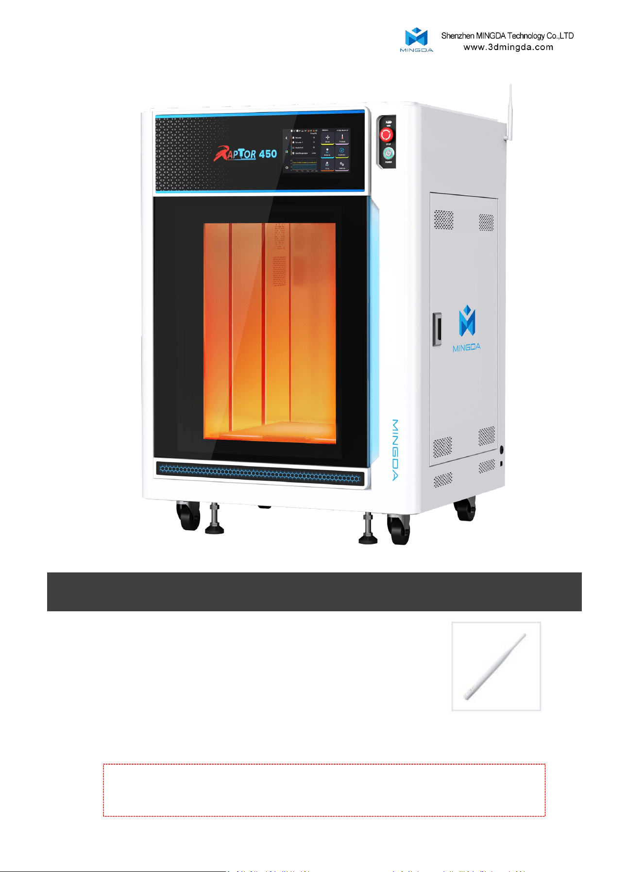
Packing List
Tool List
Note: The picture is for reference only. When the real thing is inconsistent with
the picture, the actual object shall prevail.
U-disk
Allen wrench Antenna
3
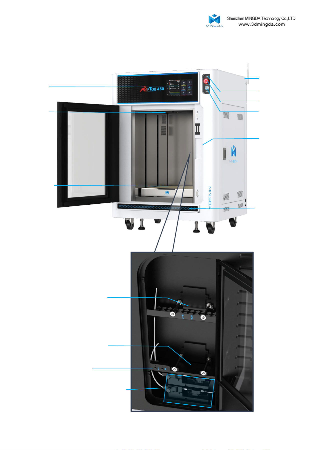
Machine Components Overview
2. Toolhead
1. Display
7. Power on button
6. Emergency button
5. USB port
8. Indicator Light
3. Build plate
9. Ambient Lighting
4
4. Antenna
12. Extusion board
10. Filament Holder Left
11. Filament Holder Right
13. Filament Feeding Assembly
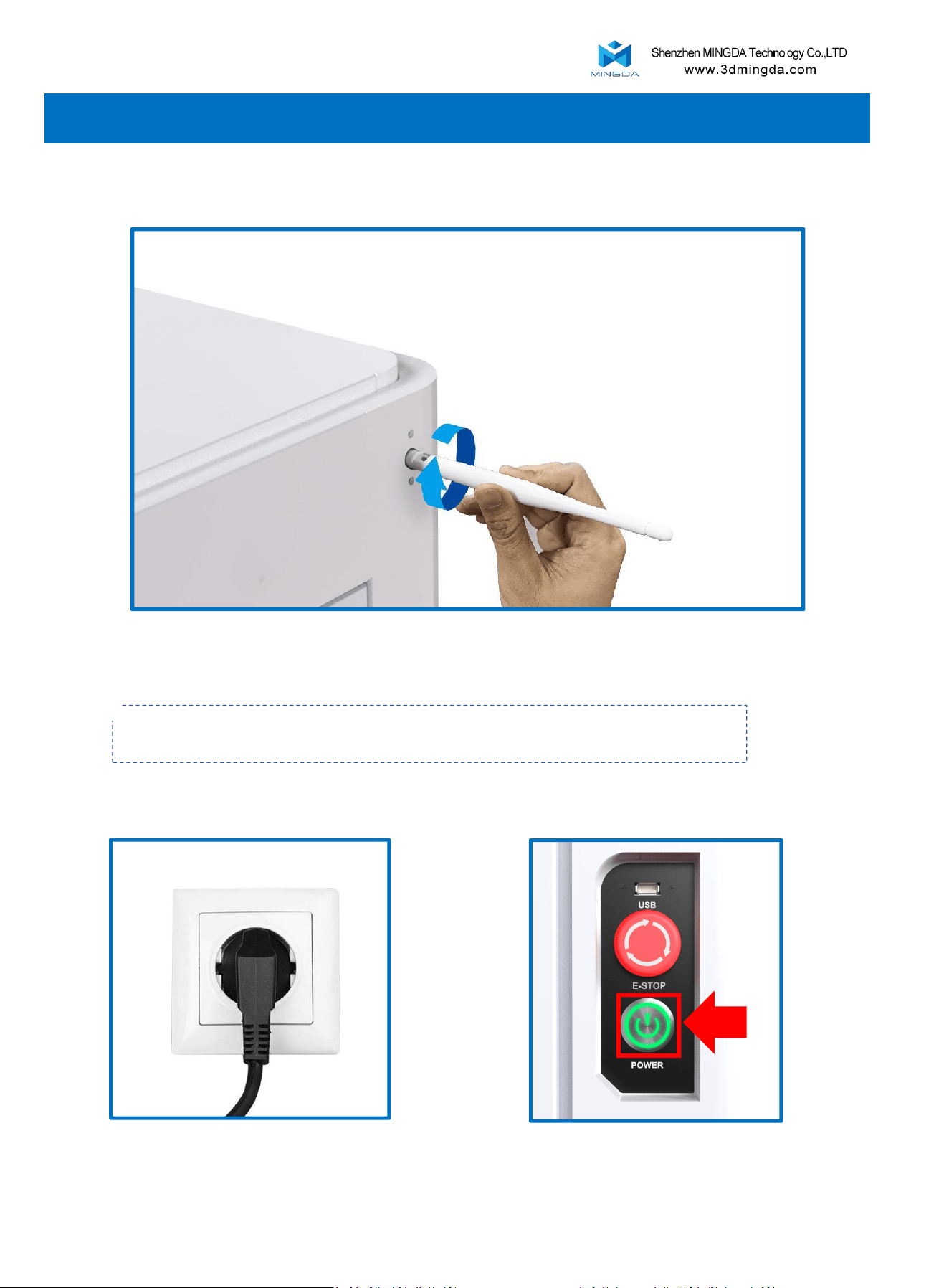
3. Operational Steps
2. Power on
Press the power button to turn on the printer
5
1. Install the Antenna
Please make sure the voltage is correct before plugging in.
Insert a power socket, Press the switch
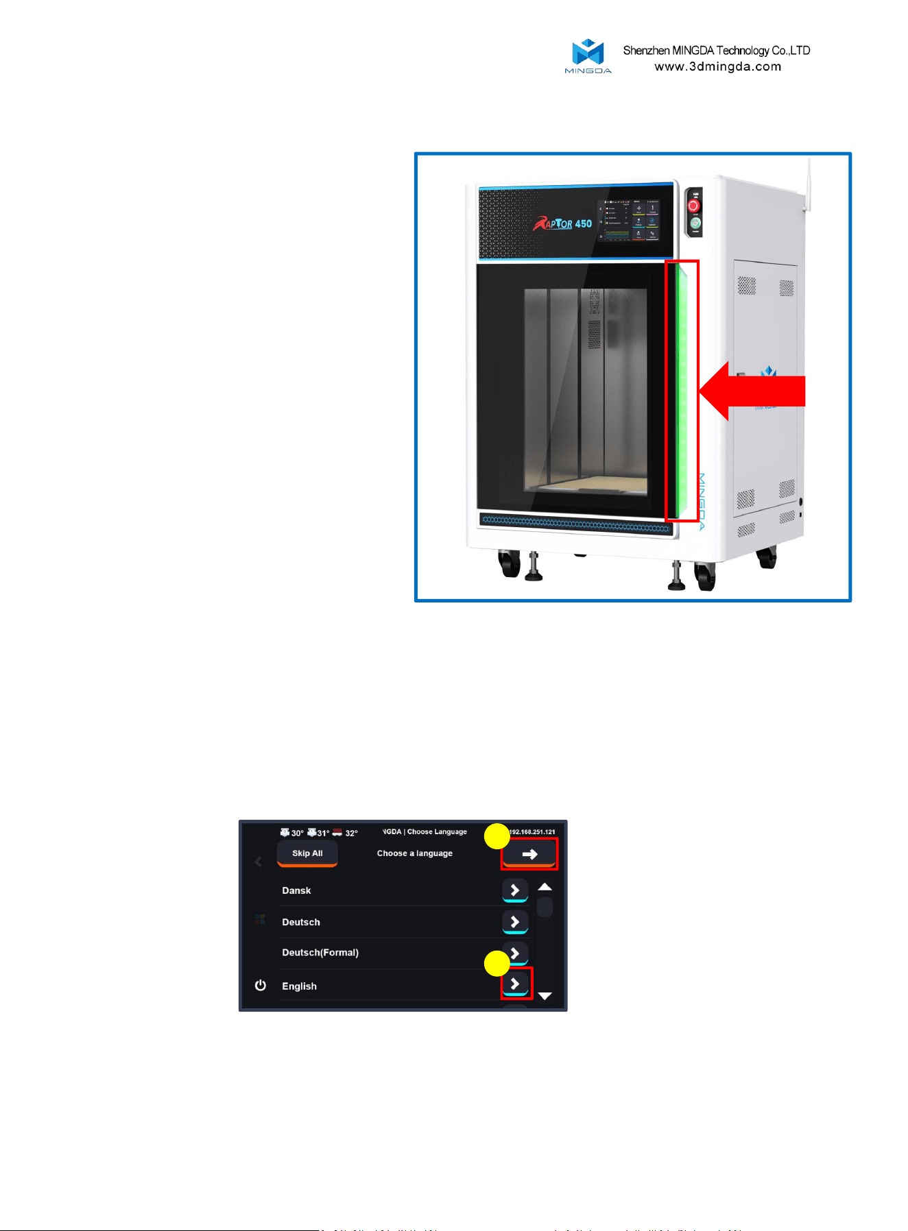
Click to choose the language, and click to proceed to the next step.
1
2
3. Select Language
Startup Configuration
6
2. Indicator light
Standby Mode: Acts as a general status
indicator.
Green light: Indicates that the printer is
working properly.
Red light: Indicates that the printer is in an
emergency stop or fault state, requiring
immediate attention or repair by the user.
For example, overload, short circuit, or
error message on the screen.
Yellow light: Indicates that the printer is in
a warning or abnormal state, requiring
user attention or intervention. For
example, insufficient filament or paused
printing.
Printing Mode: Transforms into a dynamic
progress bar, Green LEDs indicate the
completed portion, while yellow LEDs
indicate the remaining portion.
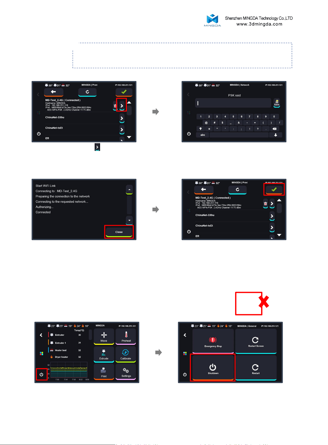
4. Wi-Fi
Note: If you find that the printer cannot detect your WiFi signal, you can click to skip
this step for now. After completing the startup wizard, move the printer to a location closer to a
stronger signal source, and then reconnect to WiFi.
Enter the WiFi password and click
Select the WiFi and click
(If your WiFi network does not appear within 20
seconds, click the refresh button to
search again.)
Upon successful connection, click the in the
upper right corner to enter the main interface of the
machine. If you do not need to connect to the network,
you can also click the to skip this step.
Once the connection is successful, click
3. Power off
When you turn off the printer, please don't press the power directly!
Click " Shutdown " to turn off the printer
Click the "Shutdown"
7
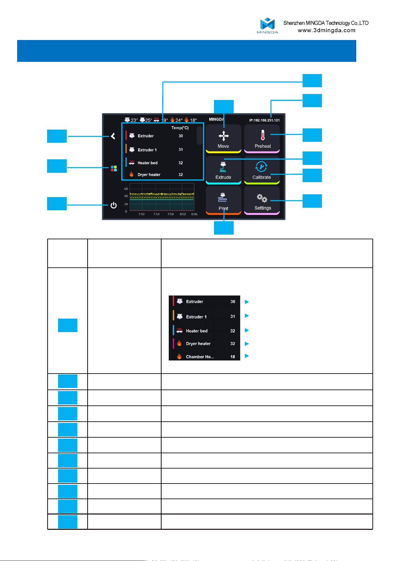
Primary interface
Explain
Temperature
Temperature display area
IP
Network IP address
Move
Move or home XYZ axis
Preheat
Pre-set nozzle & hotbed’s temperature
Extrude
Load/Unload filament.
Calibrate
Printer Calibration
Settings
Printer settings, hardware controls, and system tools.
Print
Start printing
Shutdown
Shutdown, restart, and emergency stop.
Homepage
Return to the main page
Return
Return to the previous page
Main interface
11
10
09
01
02
04
05
06
08
07
03
01
02
03
04
05
06
07
08
09
10
11
4. Operating interface introduction
Right extruder
Left extruder
Hotbed
Dryer heater
Temperature-controlled chamber
8
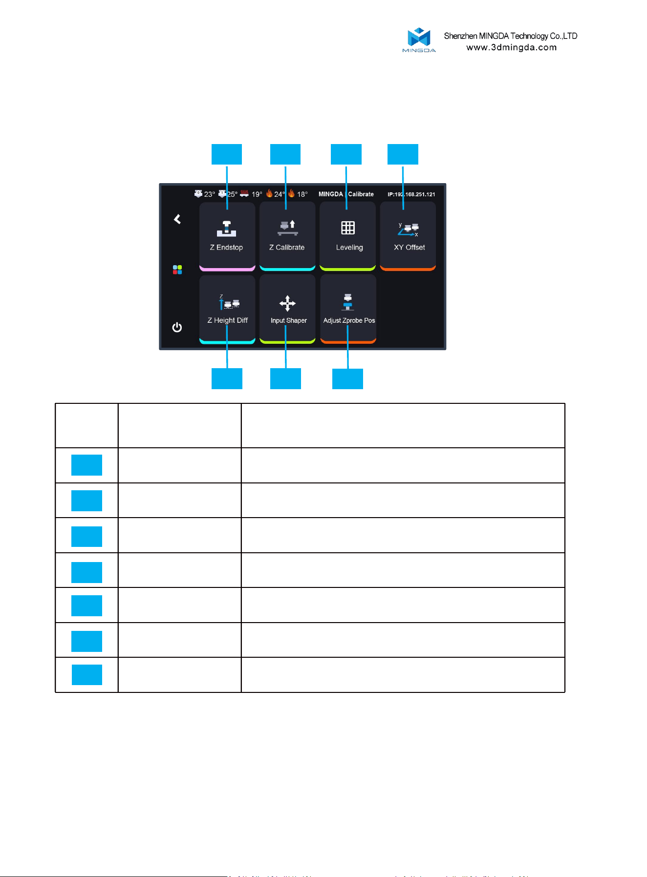
Calibrate:
Secondary interface
Explain
Z Endstop
Adjust the position of the photoelectric switch.
Z Calibrate
Leveling sensor calibration
Leveling
Auto-leveling
XY Offset
Calibrate X/Y offsets to align left and right nozzles
Z Height Diff
Calibrate Z offsets to align left and right nozzles.
Input Shaper
Test the resonance compensation value.
Adjust Zprobe Pos
Confirm the position of the Z-height difference calibration
probe.
01
02
03
04
05
06
01 02
03
04
05 06
07
07
9
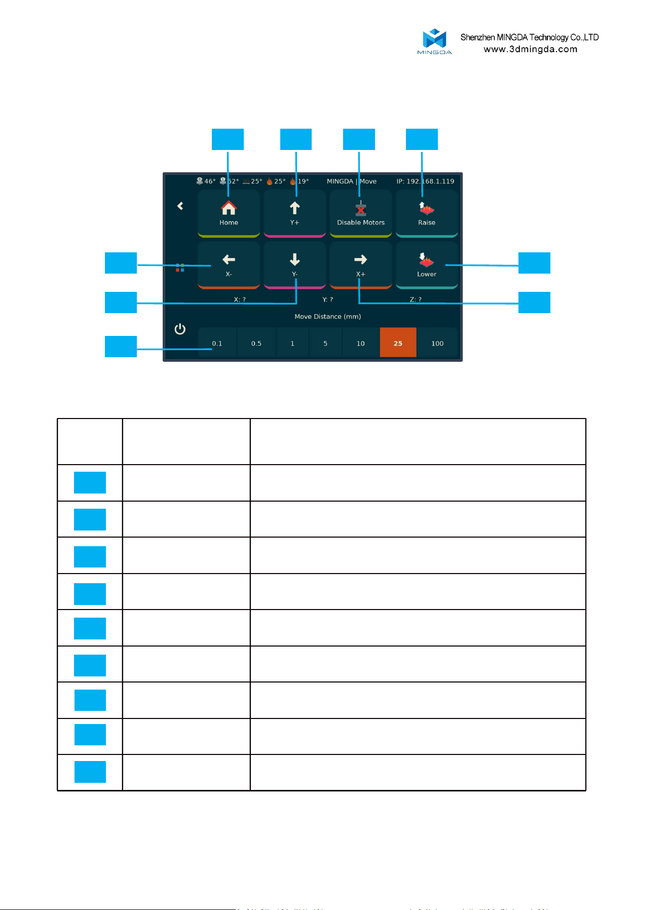
Secondary interface
Explain
Home
Restore XYZ axis positions
Y+
Adjust Y-axis position
Disable Motors
Unlock motor restriction
Raise
Raise platform
Lower
Lower platform
X+
Adjust X-axis position
X-
Adjust X-axis position
Y-
Adjust Y-axis position
Move Distance
Select the distance to move
01
02
03
04
05
06
01 02
03
04
09
06
07
08
05
Move:
08
07
09
10
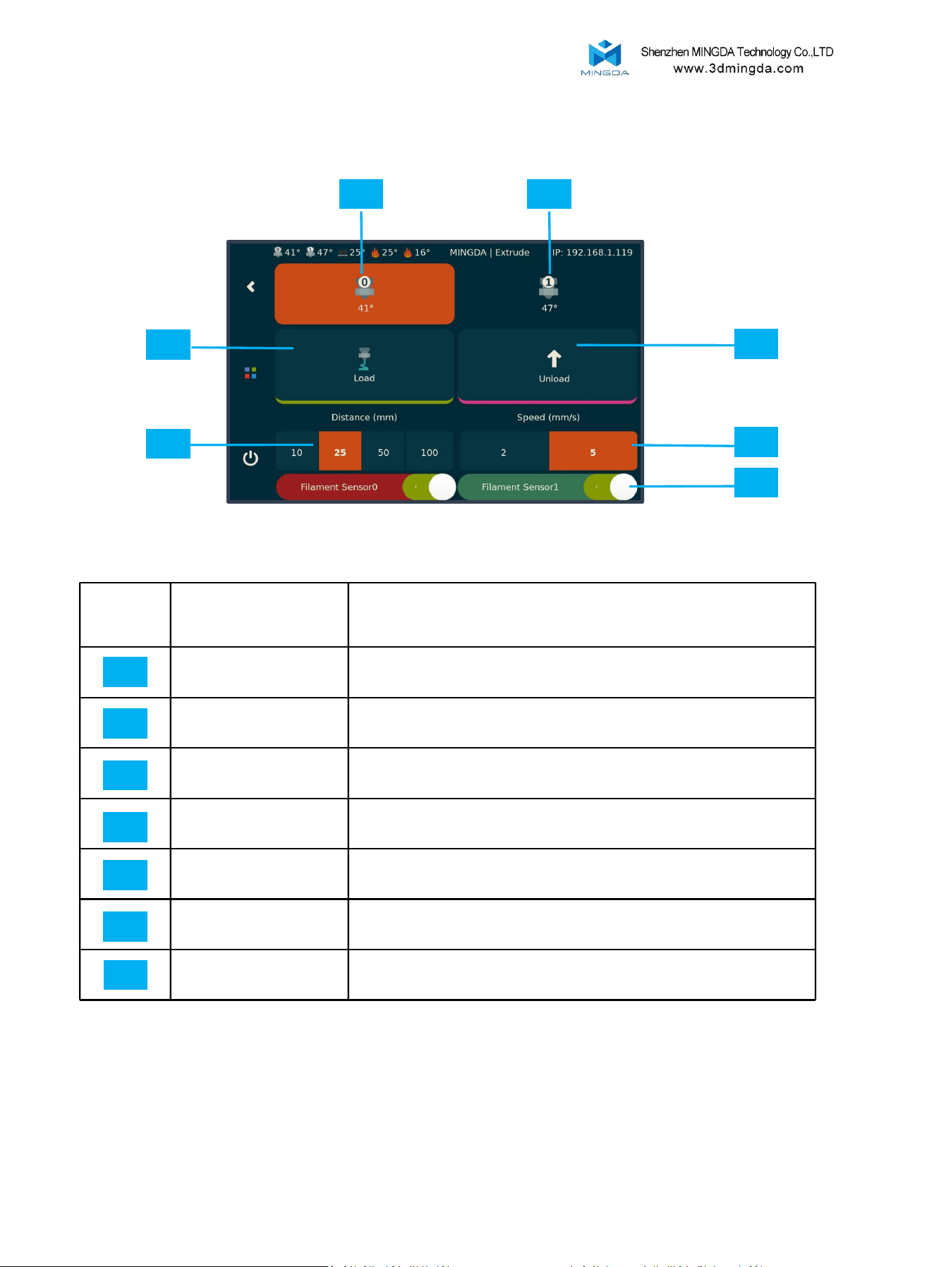
11
Secondary interface
Explain
Extruder
Switch to left extruder
Extruder1
Switch to right extruder
Load
Extrude filament
Unload
Unload filament
Distance
Distance(mm) settings
Speed
Speed(mm/s) settings
Filament Sensor
Check for filament presence
01
02
03
04
05
06
01 02
07
04
07
Extrude:
05
03
06
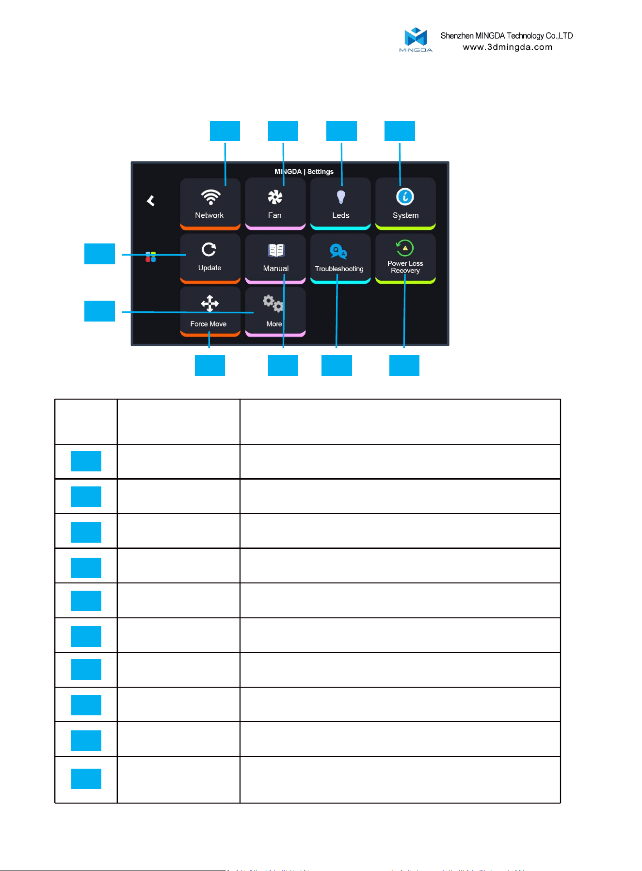
Settings:
Secondary interface
Explain
Network
To connect Wi-Fi
Fan
Cooling fan adjustment
Leds
Turn on/off Light
System
Machine shutdown, restart, reset function
Update
Update Klipper and Klipperscreen
Manual
Manual
Troubleshooting
Troubleshooting
Power Loss Recovery
Resume the print after a power failure or system error
Force move
Move the toolhead if necessary before resuming the print
More
Includes some basic settings such as language, screen
timeout, notification sound toggle, and automatic
shutdown after printing completion.
01
02
03
04
05
06
07
08
09
10
05
06 07
01 02
03
04
0809
10
12
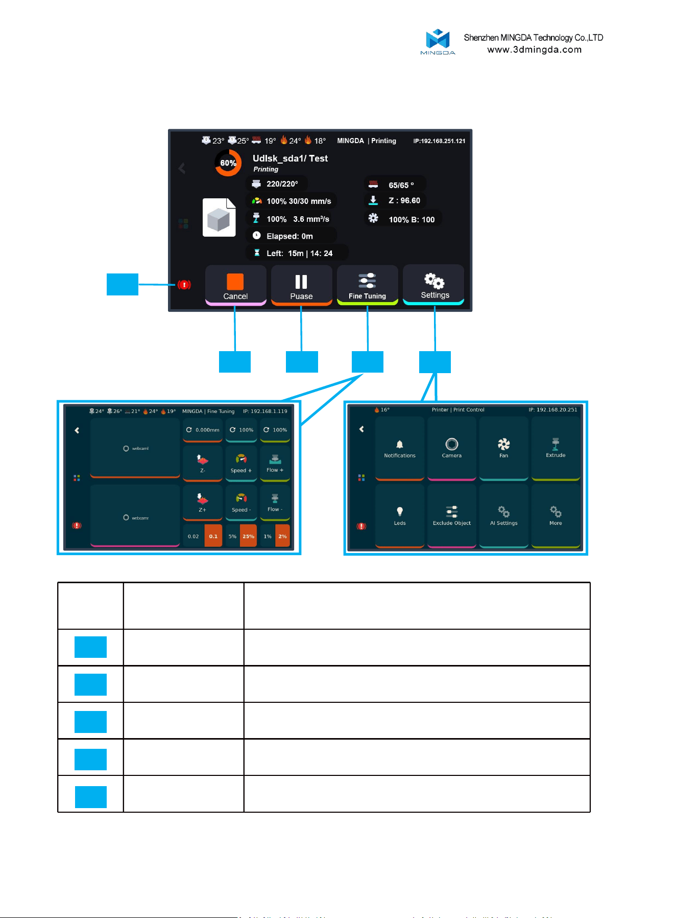
Secondary
interface
Explain
Cancel
Stop printing
Pause
Pause printing
Fine Tuning
Adjust Z-offset, Printing Speed, Printing Flow
[Please refer to Figure 1.]
Settings
Basic setting, browse camera, adjust cooling fan, light ,
Extrude and Exclude object. [Please refer to Figure 2.]
Stop
Emergency stop .
Printing Interface:
01
02
03
04
01 02
03
04
Figure 2
Figure 1
05
05
13
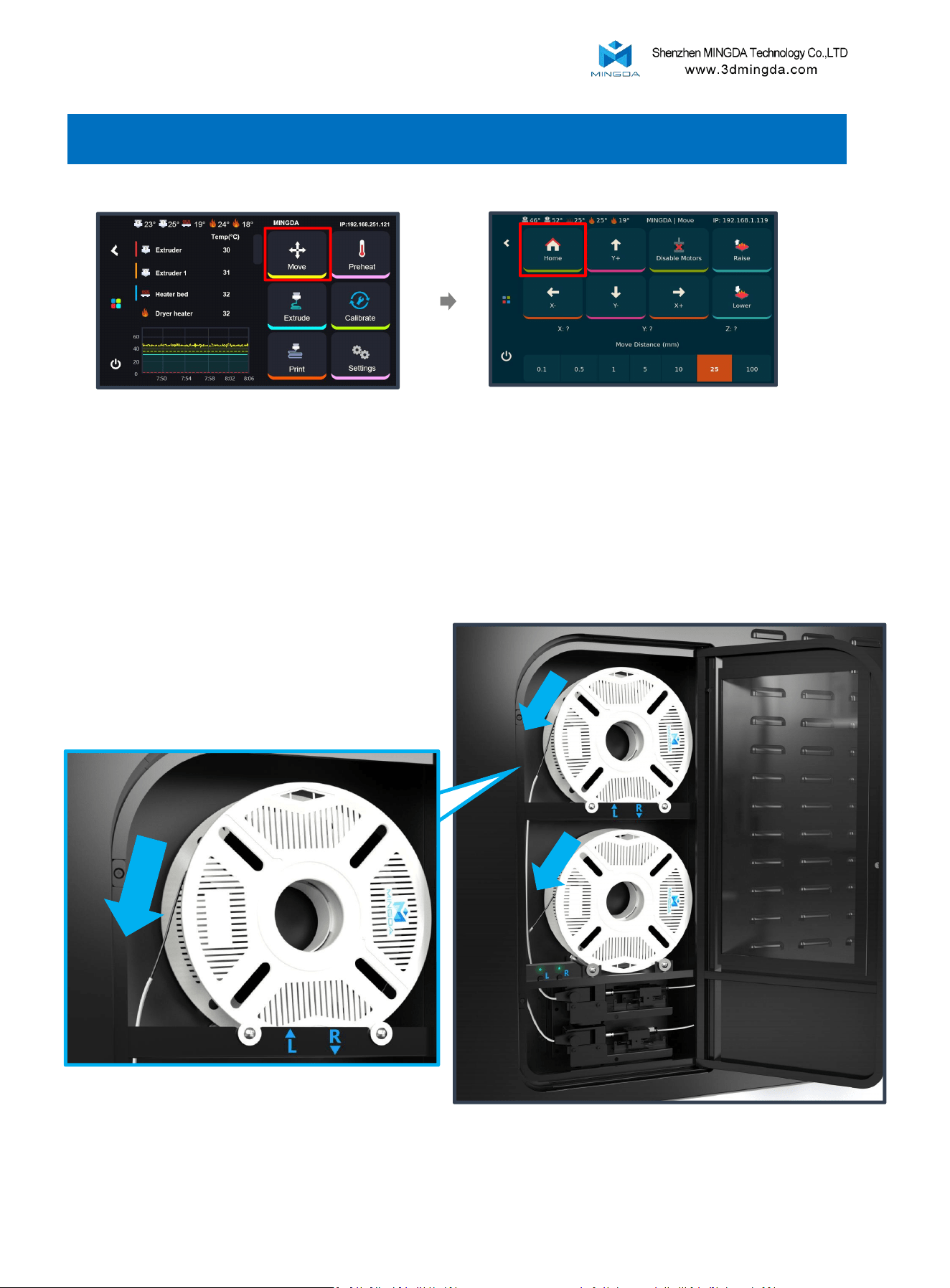
5. Insert filament
3.Hang the filament onto the filament holder as shown in the picture, and insert the filament into the
corresponding tube and push it until it cannot be pushed anymore. The internal gears will automatically
pull the filament in.
1. Click the "Move"
2. Click the "Home" - "Home All"
14
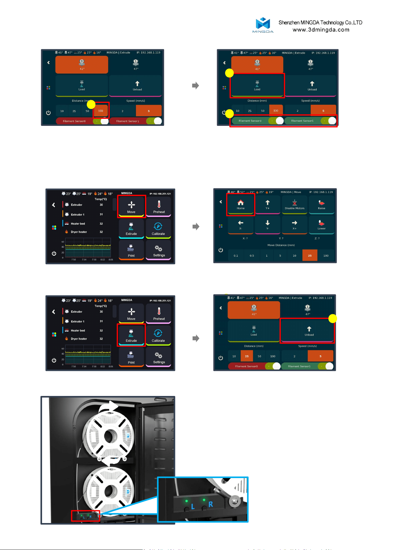
6. Select a length of 100mm, 7. Click the "Load" button until the filament
sensor indicator changes from red to green.
1
1
2
Unload Filament
1
3. Click the "Extrude"
1. Click the "Move"
2. Click the "Home" - "Home All"
1
4. Select the extrude for unload; Click the
"Unload" button; Wait for retraction to
complete.
5. Press the button corresponding to the print head
on the auxiliary feeding plate until the consumables
are completely removed
15
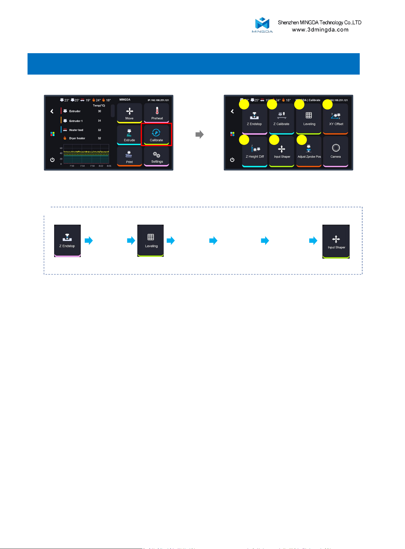
6. Printer Calibration
Tip: Please follow the sequence shown in the diagram to calibrate step by step.
1
2
3
4
6
Z Endstop → Z Calibrate → Leveling → XY Offset → Adjust Zprobe Pos → Z Height Diff → Input Shaper
Click "Calibrate "
7
5
Note:
1. Z-Endstop,Z-calibrate, Auto-leveling, XY offset and Z height diff must be performed
after replacing the nozzle, hotend, or removing/reinstalling the extruder.
2. Before starting the Z-Endstop,Z-calibrate, Auto-leveling process, heat the bed to
the target printing temperature, and wait for 20 minutes. This allows for thermal
expansion of the PEI to stabilize, ensuring accurate leveling.
Printing Tips:
If the bed calibration temperature is set to 60°C. Before printing, keep the bed
temperature at 60°C and wait for 20 minutes to ensure optimal first layer adhesion
and print quality.
16
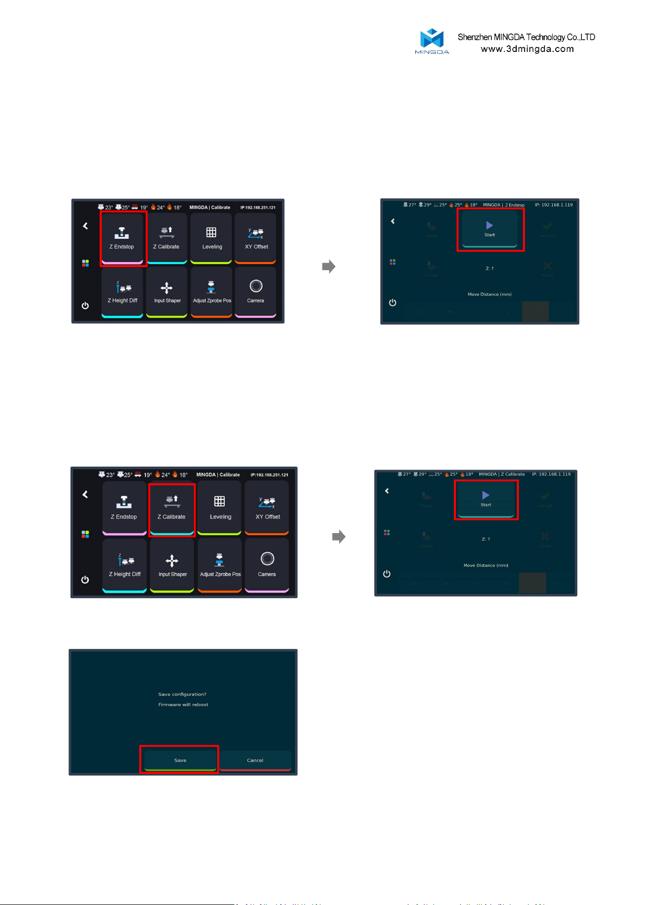
2. Z Calibrate
1. Click "Z Calibrate"
2. Click "Start" , waiting for
automatic calibration to complete.
3. Click "Save" and confirm
1. Z Endstop
Adjust the position of the photoelectric switch.
Click "Z Endstop"
Click "Start" , waiting for
automatic calibration to complete.
Note: Clean the nozzle thoroughly before calibration.
17
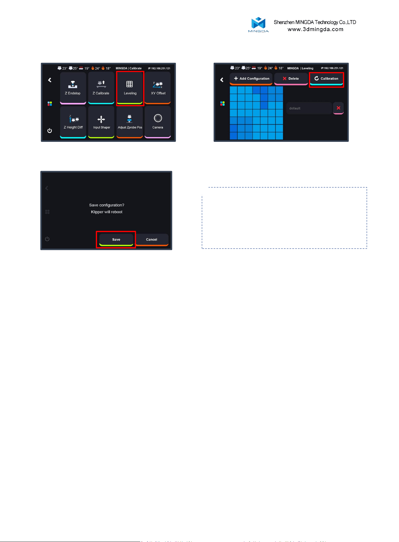
3. Auto Bed Leveling
Click to save the value,
the printer will reboot automatically.
Click to start auto-leveling,
which will take approximately 3 minutes
Click "Leveling"
Printing Tips:
1. Bed Leveling Frequency:
It is recommended to perform bed leveling every 20–25 print jobs. The Frequent
removal and repositioning of the heated bed can gradually lead to positional
deviation. Timely leveling ensures consistent print quality.
2. How to Determine if Leveling is Needed during printing:
Carefully observe the first layer when starting a new print. If there is a large gap
between the nozzle and the heated bed, poor adhesion, warping, curling, or uneven
extrusion (e.g., some areas too thick, others too thin, or broken lines), it indicates
that bed leveling is required.
Tips: It is better to heat up the bed to
the target degrees and keep it warm up
for 5-10 minutes before leveling.
18

2
1
2
1
Connect the calibration device’s wiring. Click
"XY Offset"
Click the "Calibration"
After the camera Led light up, Click "Start" ,
and the left extruder will move to the
calibration camera's position.
Click the "Save"
Adjust the left extruder nozzle to align with
the crosshairs of the screen and click
"Confirm Pos"
Adjust the right extruder nozzle to align with the
crosshairs of the screen click
4. XY Offset Calibration
Tips: Wipe the nozzle clean before calibration to avoid any interference during the process.
1
Wait for the left extruder will move to the
calibration camera's position.
19
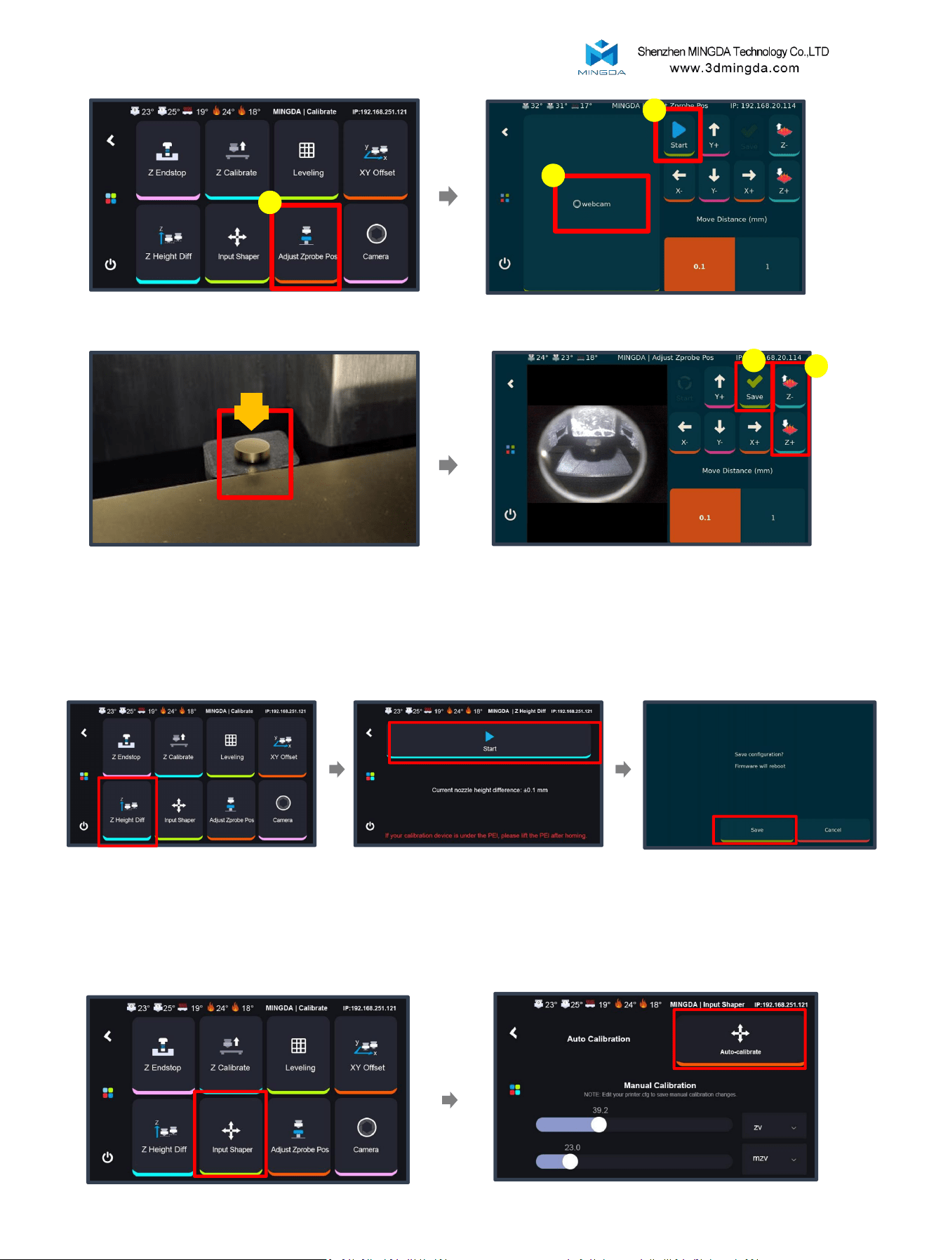
6. Z Height Diff Calibration
5. Adjust Z probe Pos
1
2
2
1
Click the "Adjust Z probe Pos"
Wait for the printhead to move to the
calibration position.
Open the " camera" button; Click the "Start" button;
1
Click the button to raise or lower the hotbed
while observing whether the nozzle contacts the probe; If
contact is not made, manually adjust the position of the
calibration device; After calibration is complete, click
"Save" , then proceed to the "Z Height Diff" page.
Wait for calibration to complete,
then click the "Save".
Click "Z Height Diff"
Click “Start” to start Z offset
automatically.
7. Input Shaper
Click "Input Shaper"
Click "Auto-calibrate",After calibration is
complete, click the save button.
20
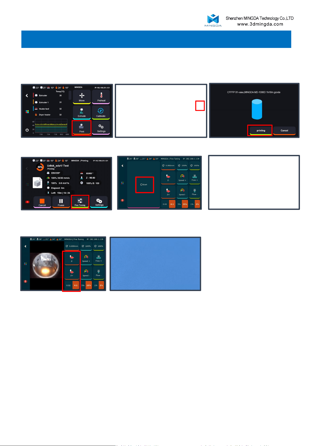
Test Printing
Before printing, please test the gcode which shipped from the printer first
Click “Print”
Click Print icon
7. Printing
Observe the first layer during
printing
Click Fine-tuning
Select the distance at 0.02
and increase the Z-offset
until the line is smooth
The final result after adjusting
The first layer very important
1. There are gaps between each lines,
that means the Z-offset need to be
lower.
2. There are waves on the printing
surface, that means the Z-offset need
to be higher
Explain:
Click “Printing”
Open the “camera”
Printing Tips:
During printing, if the model is too close to or too far from the build plate, you can use
the fine-tuning function to adjust the nozzle height:
1. Tap "Fine Tune".
2. Select a tuning step of 0.02, then use Z+ (raise the nozzle) or Z− (lower the nozzle) to
adjust the height until the extrusion lines are evenly laid and properly aligned.
Proper fine-tuning helps achieve optimal first-layer adhesion and print quality.
21
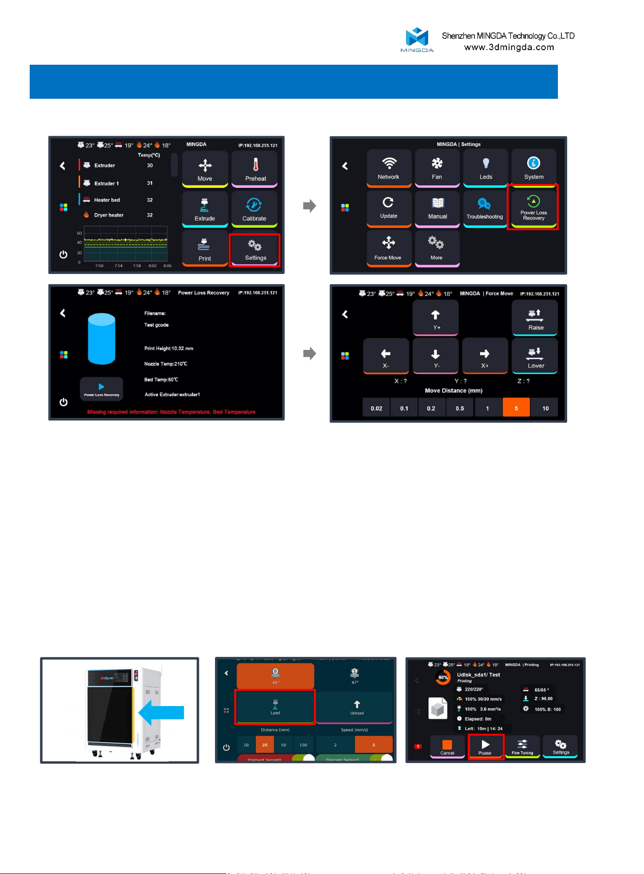
1. Resume printing after power off
2. Resume printing after filament run out
The printer will pause, and the
yellow indicator light will turn on
Replace new filament into the
extruder, click load till the filament
was feed out.
Click “Resume” , continue to
print from the point of interruption.
8. Resume Printing
Note:
1. If the printed height is less than 1 mm, resume printing is not supported.
2. Prior to resuming the print, verify whether the nozzle has dropped. If so, use the "Force Move" function to position it
approximately 0.1 mm above the model surface.
3. After resuming the print, closely monitor the printing process and adjust the Z-offset via fine-tuning if necessary.
Once power is restored, turn on the printer. It will perform a self-check automatically.
Then go to Settings > Power Loss Recovery to resume printing.
22
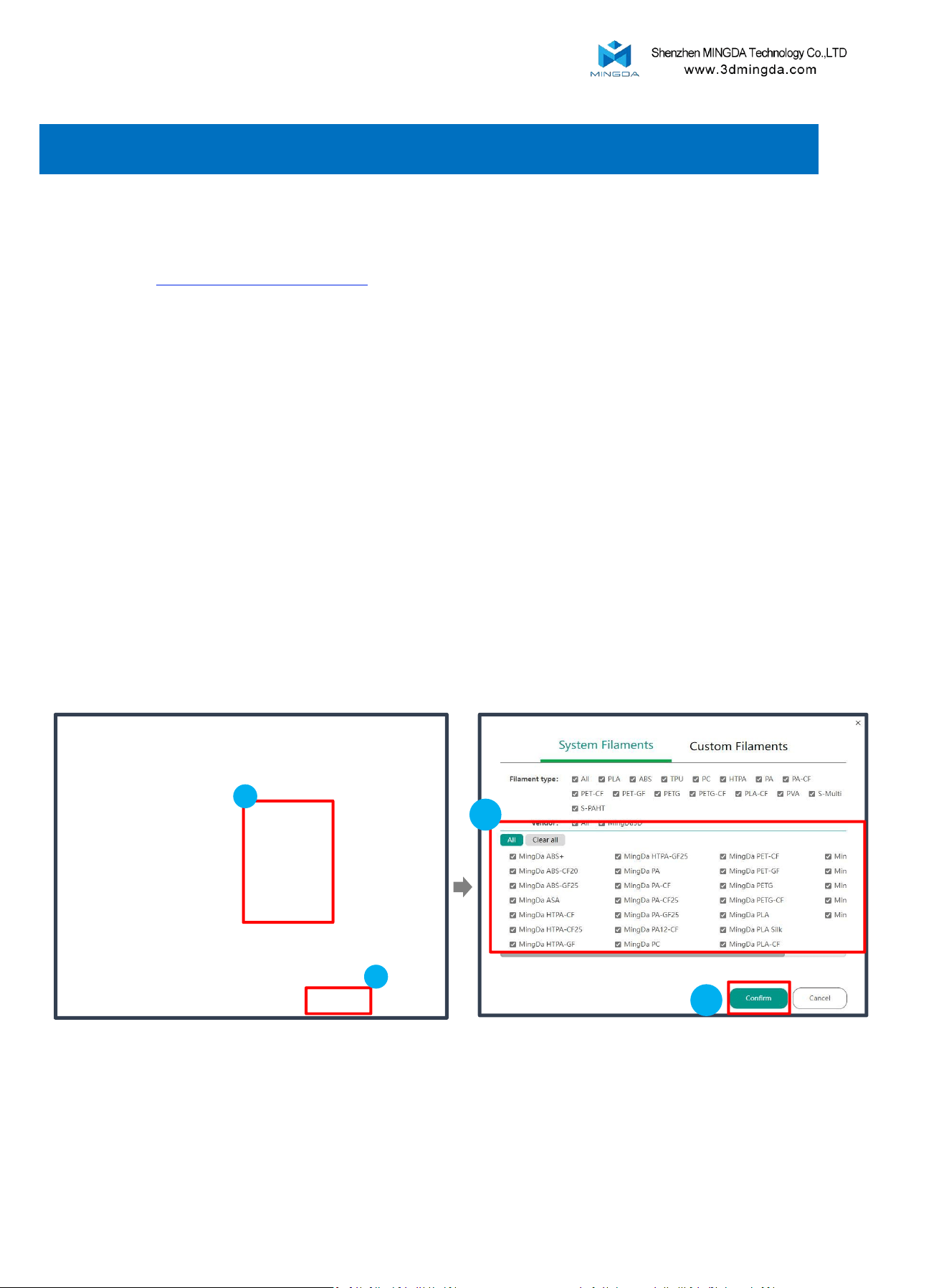
Upon the first run of Mingda OrcaSlicer, you will enter the configuration wizard.
Choose the Raptor 450 model and click "Confirm."
Select the desired filament type.
Installation:
Configuration:
1
2
2
1
Search "www.3dmingda.com/download" in any browser.
Download "MINGDA OrcaSlicer"
9. Slicing Software Installation and Usage
23
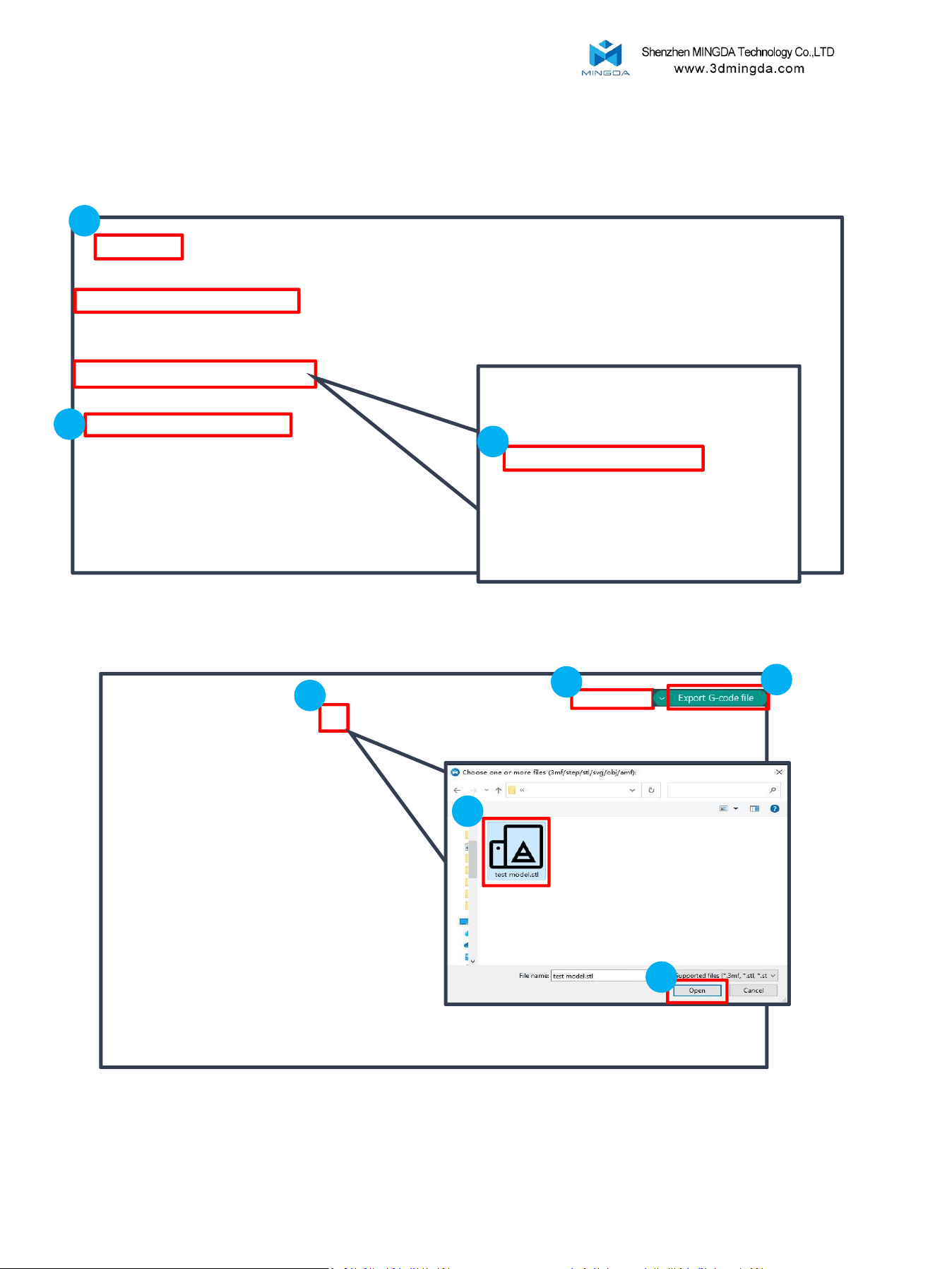
Select the printer model, filament type and printing parameter.
Usage
Click the "Prepare"
1
3
1
2
2
3
4
Click , upload your STL in the slicer, adjust your model parameter, after finishing, click “Slice plate” to
create the Gcode file.
2
24
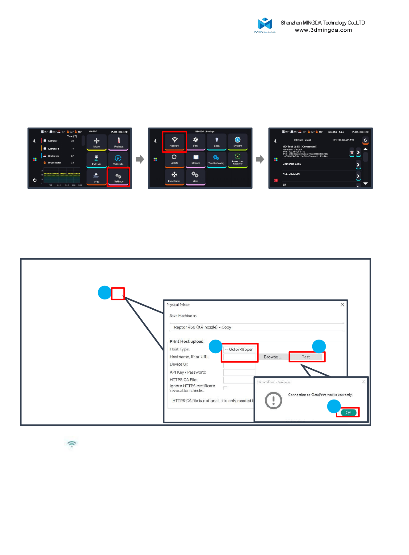
Printing method
1
Click WIFI , select Host type as Octo/Klipper, enter the printer’s IP address, and click “Test” and “OK”
LAN Printing (Recommend)
Ensure that the printer and the computer host are on the same local network.
Click "Settings" to enter the
settings page.
Click "Network" to enter
the network page.
Check the printer's IP address.
25
2 3
4
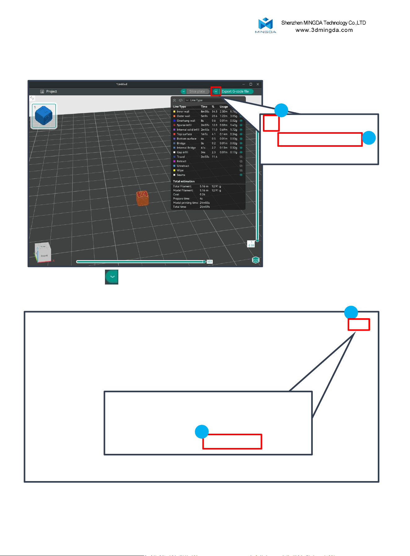
Click the dropdown icon in the top right corner , select "Print."
Click "Print" and choose "Upload and Print".
File Transfer:
1
2
1
2
LAN Printing
26
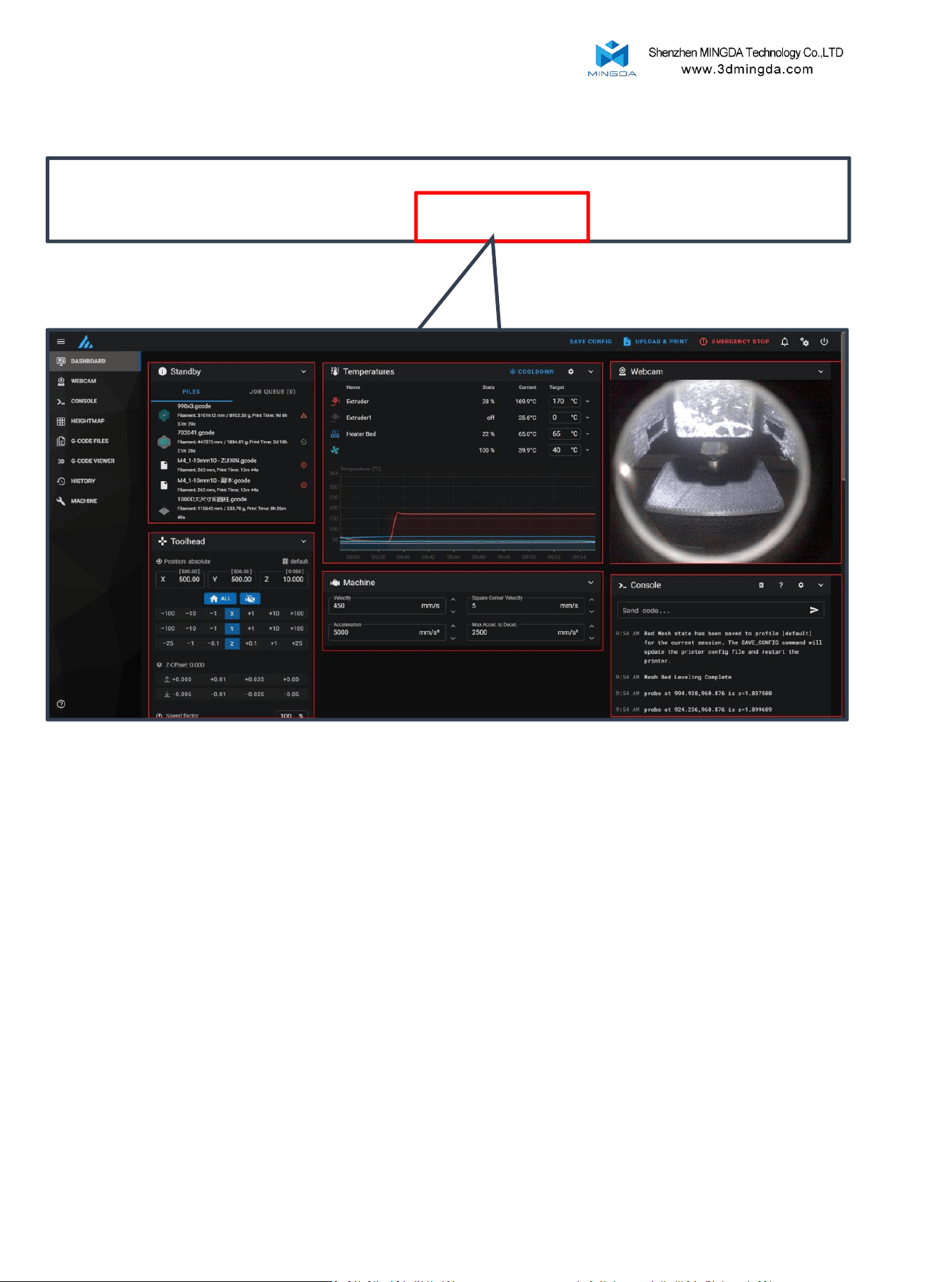
After successful connection, click on "Device"
Device Connection
1.Task List
4.Movement
Control
2.Temperature Control
5.Printer Limits
6.Console
3.Camera
Enter the control interface below the diagram
1. Task List: Drag G-code files to this task list for printing.
2. Temperature Control: Displays machine temperature changes and allows pre-setting
nozzle and bed temperatures.
3. Camera: Monitors the printing status.
4. Movement Control: Controls the movement of each axis and allows compensation
settings after leveling.
5. Printer Limits: Controls the maximum acceleration of the printer, usually doesn't need
to be changed.
6. Console: Sends G-code commands to run the machine and displays error output.
27
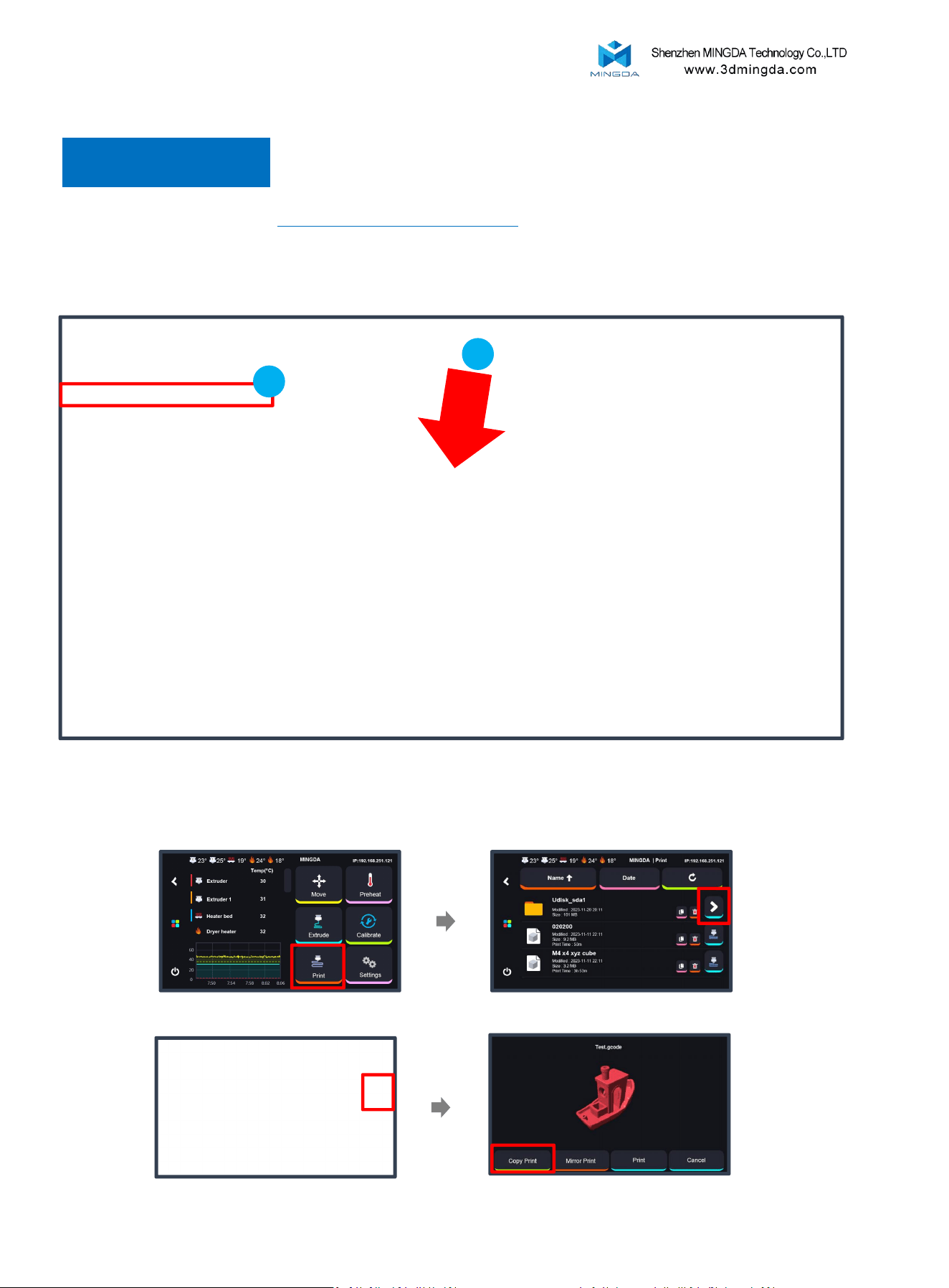
Copy Mode
Print Size: X * Y * Z: (2*225) * 450 * 450mm
Print Mode
In duplication mode, select the Raptor 450 COPY MODE (0.4 nozzle) for slicing. Place the models on the left side of
the build platform, ensuring they do not cross the blue line, as shown in the image. Then make a slicing directly and
save the gcode inside Udisk.
Insert the U-disk.
In the printer interface:
Choose the print file for printing.
Select "Print."
28
Choose “Copy Print”.
Insert the U-disk on the printer, and follow the bellow operation to make a copy printing.
Note:The model must be placed on the left side and sliced by T0 extruder.
1
2
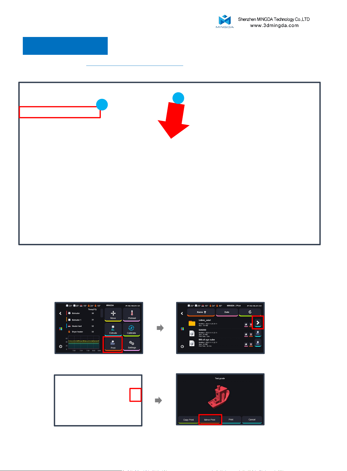
Mirror Mode
Print Size: X * Y * Z: (2*195) * 450 * 450 mm
In mirror mode, select the Raptor 450 MIRROR MODE (0.4 nozzle) for slicing. Place the models on the left side,
ensuring they do not exceed the red area on the platform in the image to prevent nozzle collisions.
In the printer interface:
29
Choose the print file for printing.
Choose “Mirror Print”.
Note:The model must be placed on the left side and sliced by T0 extruder.
Insert the U-disk on the printer, and follow the bellow operation to make a mirror printing.
Insert the U-disk.Select "Print."
1
2
Print Mode
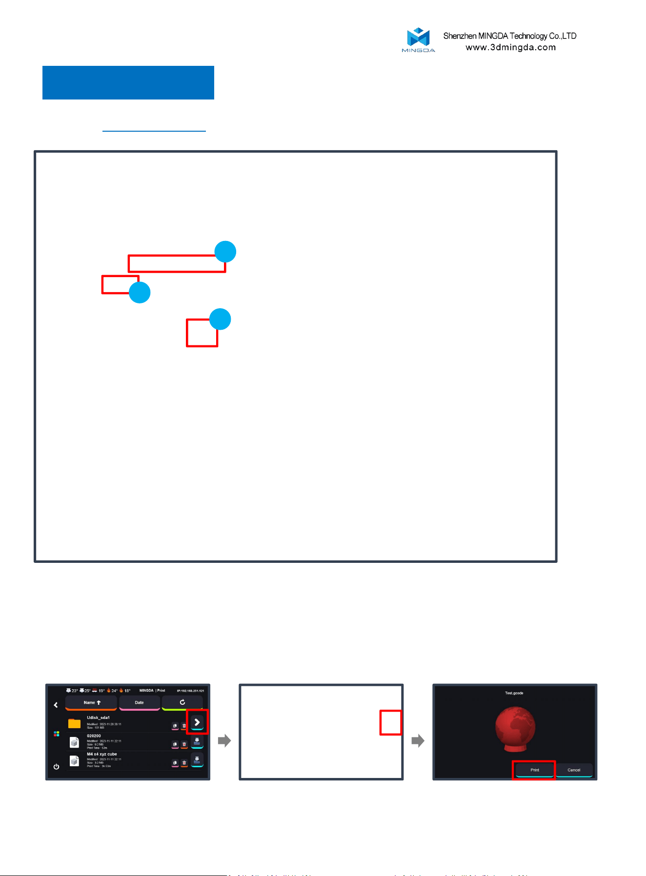
Print Mode
Print Two Colors
Printing size: 450 * 450 * 450mm
Selecting the Raptor 450 (0.4 nozzle)
2
1. Choose and modify the filament information.
2. In the Process section, click to switch to the "Objects" option.
3. Click on the color box next to the STL file to select the desired filament.
3
1
In the printer interface:
Select "Print", Insert the U-disk. Choose the print file for printing.
Choose “ Print”.
30
Double extrusion: Start the Prime tower
Because there is always one printer in standby mode during the printing process, it is easy to
cause defects such as wire drawing and material leakage. Prime tower can solve this problem,
the extruder will print a prime tower before each layer printing. Any material leakage will be
printed on the tower, effectively avoiding the phenomenon of material leakage when replacing
the extruder.
If you want to print the following two modes, we recommend adding this option to your Gcode.
1. Select the "Global" section.
2. Select the "Multimaterial" section.
3. Check the "Enable" option in the "Prime tower" settings.
1
3
2
Cautions:
1. Avoid setting the wipe tower size too small, as insufficient purging may lead to
filament mixing.
2. Ensure the prime tower is positioned away from the model to prevent overlap.
31
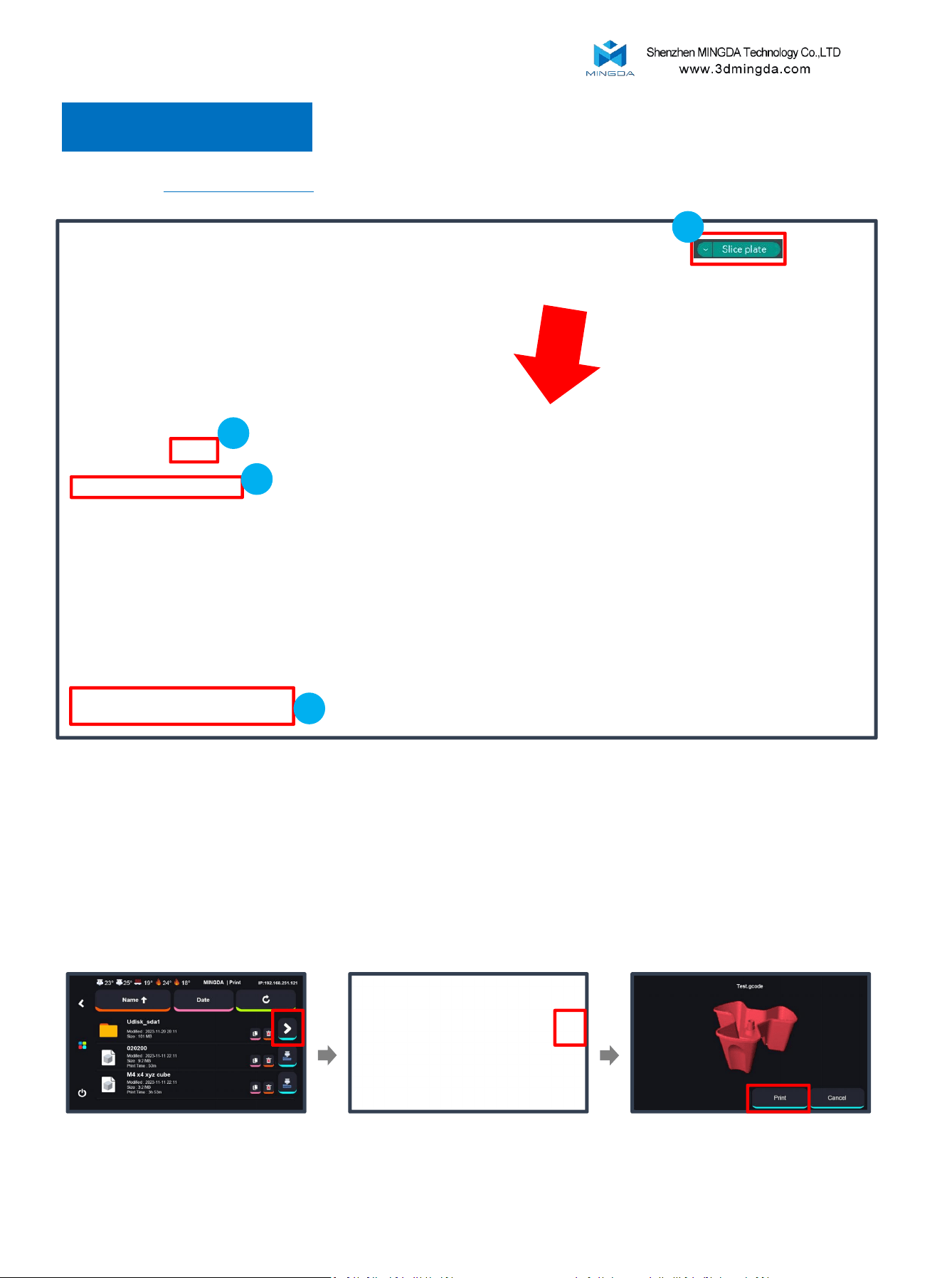
Printing Support
Printing size: 450 * 450 * 450mm
Selecting the Raptor 450 (0.4 nozzle)
4
2
3
5
1. Choose and modify the filament information.
2. Then, select the "Support" section.
3. Check the "Enable support" option.
4. In the "Filament for Supports" option, choose the filament needed for supports.
5. Click "Slice plate" to preview.
In the printer interface:
Select "Print", Insert the U-disk. Choose the print file for printing.
Choose “ Print”.
32
Print Mode

10. Maintenance and Care
Hotend:
If you print high-temperature materials or engineering materials for a long time, the inner wall of the hot end will
gradually carbonize, which will ultimately affect the extruder out of the material is not smooth, if you find that the
model has a fault or spitting material is not uniform, it may be this reason.
Replacing Filaments:
Timely replace filaments based on the type and actual usage. It is recommended to use filaments recommended by the
manufacturer. Seal filament not in use for an extended period, as excessive exposure to moisture in the air can make the
filament brittle.
PEI plate:
Please avoid touch the PEI bed by hand. It can be cleaned by dish soap with warm water and dry it by a clean cloth.
Regular Lubrication:
Once every 3 months. Home the printer first and grease it and move the Z+ to the top, then home the printer and grease
again until the screw rods full with the grease, after that clean the excess grease. If there are noise during moving. You
can grease the oil on the idler wheels when there are noise.
Software Updates:
Regularly update the printing software to improve print quality and efficiency.
33
1. Do not allow PET-GF, PET-CF, PA12-CF, HTPA-GF, HTPA-CF or S-Multi to absorb moisture.
1. Dry the filament before printing as long as you are not sure if the filament is damp.
2. After drying the filament, please store it in filament cabinet with driers
3. If the printer will not be used for an extended period, please store the filament in a sealed container, preferably in a dry
cabinet.
2. Avoid PLA-HF/PETG-HF clogged during printing
1.When printing PLA with a bed temperature above 45 °C, open the front door to prevent heat buildup and extrusion issues.
2.When printing PETG with a bed temperature around 70 °C, open the front door to prevent overheating that may cause
extrusion issues or nozzle clogging.
3. To prevent warping, take caution when printing with ABS-HF, PA12-CF, HTPA-GF, HTPA-CF, ABS-
GF25, ABS-CF20, HtPA-GF25, and HtPA-CF25.
If the model size is large and the fill rate is set high, such as 60% (the default value is 15%), warping occurs and it can be
adjusted down appropriately. In addition, change the fill pattern to a spiral to reduce the risk of shrinkage. For some
structural parts with high strength requirements, you can set 5 layers of walls and a fill rate of about 25%, and try to avoid
using a fill rate of more than 50% to reduce the shrinkage tendency; for most non-structural parts with low strength
requirements, you can directly select the default 2 layers of walls and a fill rate of 15%.
1. Set the nozzle temperature to 250–300 °C.
2. Manually unload the remaining high-temperature filament.
3. Load the new low-temperature filament and manually extrude it.
4. Continue extrusion until all residual high-temp material is flushed out and the new filament flows smoothly.
5. Lower the nozzle temperature to 220–240 °C, and continue extruding while the nozzle cools down to ensure smooth flow
of the new filament.
If extrusion fails during the flushing process, increase the nozzle temperature and consider using a cleaning needle to clear
the nozzle
11. Printing Tips for different filaments
4. After printing with high-temperature materials such as PA-CF, PET-CF, or PET-GF, and before
switching to low-temperature, lower-hardness materials like PLA or PETG, it is recommended
to follow these steps:

This device complies with part 15 of the FCC Rules. Operation is subject to the
following two conditions: (1) This device may not cause harmful interference, and (2)
this device must accept any interference received, including interference that may cause
undesired operation.
Any Changes or modifications not expressly approved by the party responsible for
compliance could void the user's authority to operate the equipment.
Note: This equipment has been tested and found to comply with the limits for a Class B
digital device, pursuant to part 15 of the FCC Rules. These limits are designed to
provide reasonable protection against harmful interference in a residential installation.
This equipment generates uses and can radiate radio frequency energy and, if not
installed and used in accordance with the instructions, may cause harmful interference
to radio communications. However, there is no guarantee that interference will not
occur in a particular installation. If this equipment does cause harmful interference to
radio or television reception, which can be determined by turning the equipment off and
on, the user is encouraged to try to correct the interference by one or more of the
following measures:
-Reorient or relocate the receiving antenna.
-Increase the separation between the equipment and receiver.
-Connect the equipment into an outlet on a circuit different from that to which the
receiver is connected.
-Consult the dealer or an experienced radio/TV technician for help.
-This equipment complies with FCC radiation exposure limits set forth for an
uncontrolled environment. This equipment should be installed and operated with
minimum distance 20cm between the radiator & your body.
Shenzhen MINGDA Technology Co., Ltd
Email: support@3dmingda.com
www.3dmingda.com
Address: No. 19, Dahe Industrial Zone, Longhua District,
Shenzhen, 518110, Guangdong Province, China.
Customer SupportOfficial Website