
3D Printer User Manual
FUNMAT PRO 310 APOLLO
Engineering Materials | Desktop Industrial
Grade

II
Contents
1 SERVICE AND SUPPORT ........................................................................................................ 1
1.1
SERVICE................................................................................................................................... 1
1.2
SAFETY INSTRUCTIONS ............................................................................................................ 1
1.2.1 Hazard Type .................................................................................................................... 1
1.2.2 Areas with Potential Safety Hazard ................................................................................. 2
1.2.3 Safety Door Lock ............................................................................................................. 4
1.2.4 Environmental Requirements........................................................................................... 5
2 SETTING AND INSTALLATION ............................................................................................. 6
2.1
GENERAL INFORMATION .......................................................................................................... 6
2.1.1 Tools that come with the Printer ..................................................................................... 6
2.1.2 Prepare Relevant Equipment for Installation .................................................................. 6
2.1.3 Check the Printer Nameplate .......................................................................................... 5
2.2
PRINTER PREPARATION ............................................................................................................ 5
2.2.1 Unpacking ....................................................................................................................... 5
2.2.2 Remove Accessories ........................................................................................................ 5
2.2.3 Unbuckle X-axis and Y-axis ............................................................................................. 6
2.2.4 Startup ............................................................................................................................. 8
2.2.5 Install the Printing Builplate ........................................................................................... 8
3 SYSTEM COMPONENTS ....................................................................................................... 11
3.1
PRINTER OVERVIEW .............................................................................................................. 11
3.2
TOP DOOR AND USER OPERATION INTERFACE ....................................................................... 12
3.3
PRINTING CHAMBER COMPONENTS ....................................................................................... 13
3.4
PRINT HEAD ASSEMBLY ........................................................................................................ 14
3.5
X-AXIS AND Y-AXIS COMPONENTS ........................................................................................ 14
3.6
Z-AXIS COMPONENTS ............................................................................................................ 17
3.7
HOTBED COMPONENTS .......................................................................................................... 18
3.8
INDEPENDENT FILAMENT BOX .............................................................................................. 19
4 USER INTERFACE .................................................................................................................. 20
4.1
OVERVIEW ............................................................................................................................. 20
4.1.1 Status Bar ...................................................................................................................... 20
4.1.2 Navigation Bar .............................................................................................................. 21
4.1.3 Display Area .................................................................................................................. 21
4.2
MAIN INTERFACE................................................................................................................... 22
4.2.1 Load Print Files ............................................................................................................ 23
4.2.2 Main Status Area ........................................................................................................... 24
4.2.3 Auxiliary Status Area ..................................................................................................... 24
4.2.4 Control Area .................................................................................................................. 25
4.3
QUEUE ................................................................................................................................... 26

III
4.4 MATERIAL ............................................................................................................................. 27
4.4.1 Material Selection ......................................................................................................... 28
4.4.2 Material Loading .......................................................................................................... 29
4.4.3 Material Unloading ....................................................................................................... 30
4.4.4 Supply Material after Out-of-material Alarm ............................................................... 32
4.4.5 Material Database Management ................................................................................... 32
4.5
TOOLS ................................................................................................................................... 36
4.5.1 Axis ................................................................................................................................ 36
4.5.2 Calibration .................................................................................................................... 37
4.5.3 Tune ............................................................................................................................... 50
4.6
SETTINGS............................................................................................................................... 52
4.6.1 Device Information ........................................................................................................ 53
4.6.2 Remote Print.................................................................................................................. 54
4.6.3 Camera Settings ............................................................................................................ 55
4.6.4 Motor Enabling ............................................................................................................. 55
4.6.5 Automatic Screensaver Settings ..................................................................................... 56
4.6.6 Manual Calibration of Printing Platform Leveling ....................................................... 38
4.6.7 Manual L&R Nozzle Z Offset ........................................................................................ 48
4.6.8 Wi-Fi Settings ................................................................................................................ 56
4.6.9 Wired Network Settings ................................................................................................. 57
4.7
OTHER INTERFACES ............................................................................................................... 58
4.7.1 Warning Prompt ............................................................................................................ 58
4.7.2 Resuming Print
.............................................................................................................. 59
4.
7.3 Command Line .............................................................................................................. 59
5 OPERATING THE PRINTER ................................................................................................. 60
5.1
STARTUP AND SHUTDOWN OF DEVICE ................................................................................... 60
5.1.1 Power on the Printer ..................................................................................................... 60
5.1.2 Power off the Printer ..................................................................................................... 61
5.2
PREPARATION OF PRINT MATERIALS ...................................................................................... 61
5.3
NOZZLE REPLACEMENT OR MATERIAL CHANGE ................................................................... 64
5.3.1 Replace the Nozzle ........................................................................................................ 65
5.3.2 Change Material before Printing .................................................................................. 66
5.3.3 Pause to Change Material ............................................................................................. 67
5
.4
BASIC PRINTING AND PROTOTYPING OPERATIONS................................................................. 68
5.4.1 Prepare the Printer ........................................................................................................ 68
5.4.2 File Slicing .................................................................................................................... 69
5.4.3 Import the Print File to the Printer ............................................................................... 73
5.4.4 Printing and Prototyping Process ................................................................................. 80
5.4.5 Duplicate/Mirror Print .................................................................................................. 81
5.4.6 Continue Printing .......................................................................................................... 83
5.4.7 Pause Printing ............................................................................................................... 85
5.4.8 Stop Prototyping ............................................................................................................ 85
5.4.9 Prototyping Alarm ......................................................................................................... 86
5.4.10 After Prototyping is Completed ................................
................................................... 86

IV
5.4.11 Locking of Front Door and Top Door .......................................................................... 87
5.5
PRINTER STATUS .................................................................................................................... 88
5.5.1 Temperature Status ........................................................................................................ 88
5.6
SOFTWARE/FIRMWARE UPDATE ............................................................................................. 89
5.6.1 Update through LAN ..................................................................................................... 89
5.6.2 Update through U-disk .................................................................................................. 93
6 MAINTENANCE ...................................................................................................................... 94
6.1
INSPECTION BEFORE EACH PRINTING .................................................................................... 94
6.1.1 Inspect the Printing Platform ........................................................................................ 94
6.1.2 Clean the Printing Chamber ......................................................................................... 94
6.1.3 Inspect the Nozzle .......................................................................................................... 94
6.1.4 Check the Humidity of the Material Chamber .............................................................. 95
6.2
MAINTENANCE AFTER EACH PRINTING ................................................................................. 96
6.2.1 Clean the Printing Buildplate........................................................................................ 96
6.2.2 Clean the Nozzle ............................................................................................................ 96
6.2.3 Clean the Chamber........................................................................................................ 96
6.3
REGULAR MAINTENANCE ...................................................................................................... 96
6.3.1 Replace the Nozzle ........................................................................................................ 96
6.3.2 Clean Feeding Gears of the Extruder ........................................................................... 97
6.3.3 Clean the Fans .............................................................................................................. 97
6.3.4 Maintenance of Moving Parts ....................................................................................... 97
6.3.5 Maintenance of Chamber Filter
.................................................................................... 99
6.
3.6 Maintenance and Replacement of Feeding Pipe ........................................................... 99
6.4
OTHERS ............................................................................................................................... 101
7 TROUBLE SHOOTING ......................................................................................................... 102

V
Record of Modification and Version Description
Version Time Description
E01 Dec 2025 First version of the Manual
1
1 Service and Support
This chapter provides information on the service and support of FUNMAT PRO 310
APOLLO desktop industrial grade 3D printers (hereinafter referred to as "FUNMAT PRO
310 APOLLO", the "printer", the "machine" or the "device"), as well as safety information
and location of safety labels.
1.1 Service
If you have any questions not covered in this manual during the use of the printer, please
contact INTAMSYS Customer Support:
Region Email
Asia-Pacific Support_APAC@intamsys.com
Europe, Middle East and Africa Support_EMEA@intamsys.com
America Support_America@intamsys.com
1.2 Safety Instructions
The following basic security tips are intended to ensure safe installation, operation, and
maintenance of INTAMSYS device, and shall not be considered as comprehensive safety
issues. The machine is a safe and reliable industrial grade 3D printer. Make sure to inspect
for and eliminate potential hazards, if any, in the printer area before using this printer.
1.2.1 Hazard Type
INTAMSYS recommends that all services be provided by qualified personnel. All personnel
who operate this printer or are near it shall understand the meaning of the following hazard
classification signs used in this manual.
[High Voltage Warning]: It indicates that high voltage exists. Keep away
from exposed circuits, and it is recommended to remove all ornaments.
[High Temperature Warning]: It indicates a high printer temperature. Be
cautious when working near components that are exposed to heat.
Always wear the safety gloves that come with the printer.
The temperature of the print head in the printer can reach up to 350℃.
The temperature of the printing platform in the printer can reach up to
160°C.

2
The temperature in the chamber of the printer can reach up to 100°C.
[Pinching Warning]: It indicates that your hands might be pinched
between two objects. One or more objects are moving in your working
area.
Please take attention that changes or modification not expressly approved by the party
responsible for compliance could void the user’s authority to operate the equipment.
This device complies with Part 15 of the FCC Rules. Operation is subject to the
following two conditions:
(1) This device may not cause harmful interference, and
(2) This device must accept any interference received, including interference that may
cause undesired operation.
This equipment complies with FCC radiation exposure limits set forth for an
uncontrolled environment. This equipment should be installed and operated with minimum
distance 20cm between the radiator & your body.
This device contains licence-exempt transmitter(s)/receiver(s) that comply with
Innovation, Science and Economic Development Canada’s licence-exempt RSS(s).
Operation is subject to the following two conditions:
(1) This device may not cause interference.
(2) This device must accept any interference, including interference that may cause
undesired operation of the device.
l'appareil contient des émetteurs/récepteurs exempts de licence qui sont conformes
aux CNR exempts de licence d’Innovation, Sciences et Développement économique
Canada. L’exploitation est soumise aux deux conditions suivantes :
(1) l'appareil ne doit pas produire de brouillage,
(2) l'utilisateur de l'appareil doit accepter tout brouillage radioélectrique subi, même si
le brouillage est susceptible d'en compromettre le fonctionnement.
This equipment complies with IC RSS-102 radiation exposure limits set forth for an
uncontrolled environment. This equipment should be installed and operated with minimum
distance 20cm between the radiator & your body.
ce matériel est conforme aux limites de dose d'exposition aux rayonnements, CNR-
102 énoncée dans un autre environnement.cette eqipment devrait être installé et exploité
avec distance minimale de 20 entre le radiateur et votre corps.
1.2.2Areas with Potential Safety Hazard
The following components and areas have been highlighted as with potential hazards.
Failure to follow the safety regulations might cause system faults or reliability issues.

3
Extruder
[High Temperature Warning]:
Make sure to wear safety
gloves if it is necessary to
maintain the extruder or work
inside the chamber when the
extruder is heated.
Printing platform
[High Temperature Warning]:
Make sure to wear safety
gloves if it is necessary to
remove the printing Build Plate
of the platform or work inside
the chamber when the hotbed
is high in temperature.
Chamber
[High Temperature Warning]:
Make sure to wear safety
gloves if you work inside the
chamber at medium and low
temperatures during heating; it
is not recommended to work in
the chamber at high
temperatures.
XY motion frame
[Pinching Warning]: Do not
wear tie, loose clothing, or
hanging ornaments when
working near a moving printer
component.
[Pinching Warning]: Do not
click HOME when there is a
model on the platform.
[Pinching Warning]: Be careful
when maintaining this moving
component.

4
Z-axis motion frame
[Pinching Sign]: Do not wear
tie, loose clothing, or hanging
ornaments when working near
a moving printer component.
[Avoid Collision]: If there is a
printed model on the platform,
be care to raise the platform to
a proper height to prevent
puncturing the organ cover;
[Avoid Collision]: If there is an
object under the platform, be
care to lower the platform to a
proper height to prevent
deformation of drive rod parts
and leveling failure caused by
platform collision.
1.2.3 Safety Door Lock
Sensors are used to monitor the status of the chamber front door and printer top cover. For
the purpose of safety, the chamber door and top cover shall be closed before the XYZ
motor can start working. The electromagnetic lock ensures that the chamber door and top
cover remain securely closed during printing.
Fig. 1.1 Safety Door Lock
Front door sensor
Electric magnetic lock of
front door

5
1.2.4 Environmental Requirements
The printer is for indoor use only.
Air quality conditions (conductive or non-conductive) with excessive solid
particles might cause damage to the system.
The printer shall operate between 0°C and 30°C (32°F to 86°F) with a relative
humidity range of 20% to 70% (non-condensing).
The printer storage temperature shall be between -20°C and 55°C (-4°F to 131°F)
with a relative humidity range of 10% to 90% (non-condensing).
1.2.5 Regarding battery warning
replacement of a battery with an incorrect type that can defeat a safeguard (for
example, in the case of some lithium battery types);
disposal of a battery into fire or a hot oven, or mechanically crushing or cutting of
a battery, that can result in an explosion;
leaving a battery in an extremely high temperature surrounding environment that
can result in an explosion or the leakage of flammable liquid or gas; and
a battery subjected to extremely low air pressure that may result in an explosion
or the leakage of flammable liquid or gas.
6
2 Setting and Installation
This chapter describes the basic settings and installation of FUNMAT PRO 310 APOLLO.
2.1 General Information
2.1.1 Tools that come with the Printer
Please check the packing list that comes with the printer. These tools include common
tools required for printer maintenance and various spare parts.
2.1.2 Prepare Relevant Equipment for Installation
The guide for preparation of installation site ensures that relevant equipment for printer
installation can be prepared effectively and safely.
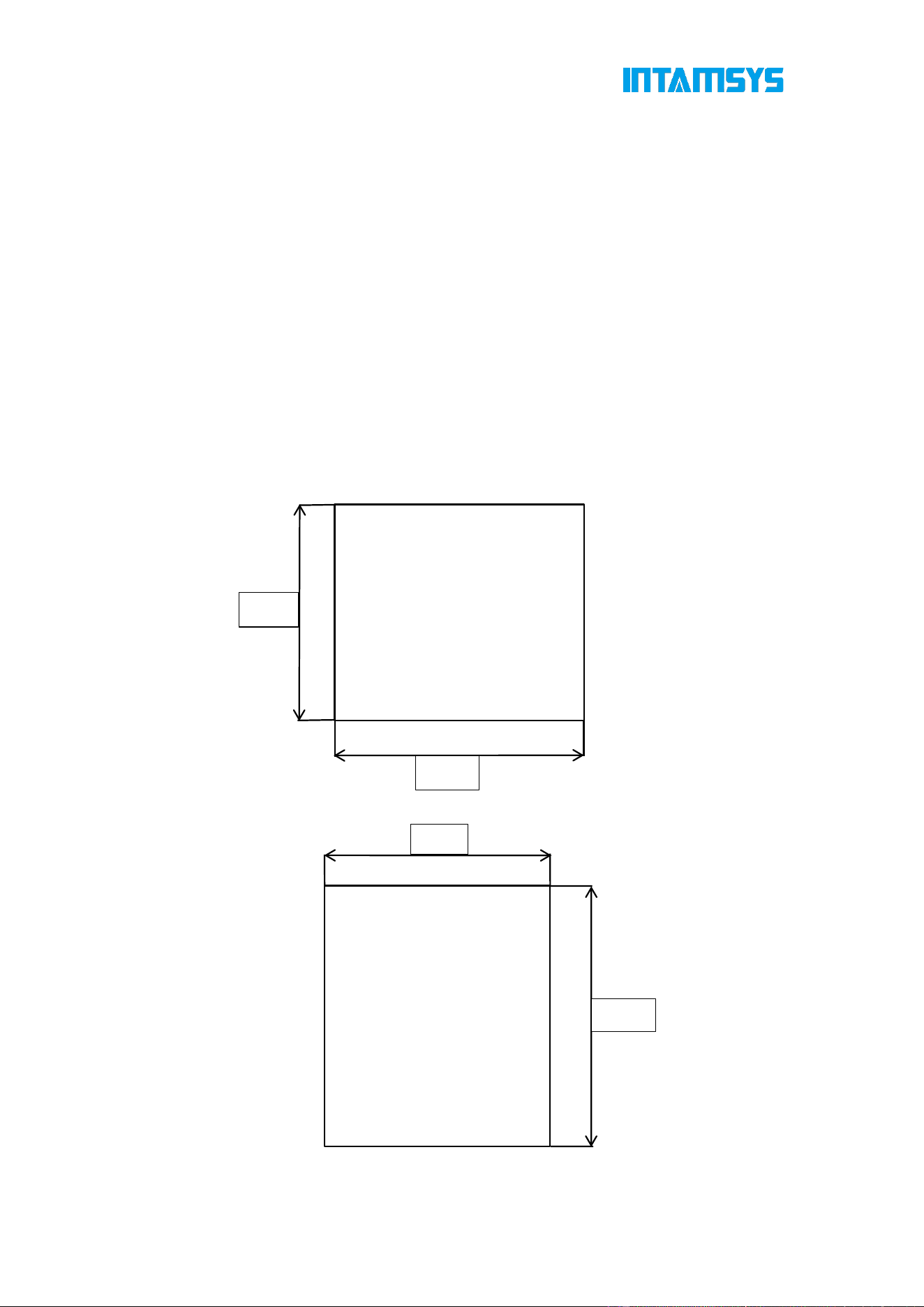
Fig. 2.1 Space Required for Installation and Maintenance (Unit: mm)
1100
1200
750
1100

5
2.1.3 Check the Printer Nameplate
Refer to the figure below to identify your printer.
Model information: Product name, model number and power requirements. This nameplate
also lists the relevant certifications and INTAMSYS information.
SKU: Lists the SKU of the printer. Upon a service request, provide this SKU to the agent
or INTAMSYS, so that service personnel can quickly identify your printer configuration.
Fig. 2.2 Printer Nameplate
2.2 Printer Preparation
2.2.1 Unpacking
Step 1:Remove the protective film and fixing tape on the outside of the packaging box.
Step 2:Remove the wooden board at the top of the packaging box and the top cover of
the packaging box in sequence.
Step 3:Remove the cardboard and foam around the packing box.
Lift the printer from the bottom and place it to a stable platform (at least two people are
required).
Fig. 2.3 Schematic Diagram of Packaging Removal
2.2.2 Remove Accessories
Open the front door of the device from the front, and carefully take out the accompanying

6
accessories and material boxes. As the platform would be tightly compressed against
internally packaged foam cotton due to the impact of vibration and self-gravity during
transportation, the machine shall be energized to raise and reset the platform before
removing the accompanying accessories and material boxes. Refer to the Quick Start
Guide for this step.
Fig. 2.4 Removing Accessories
2.2.3 Unbuckle X-axis and Y-axis
Step 1: Open the top door of the printer;
Step 2: The fixing block on the X-axis guide rail is used to ensure the stability of the extruder
during transportation. Unscrew the two screws on the fixing block with a 3 mm Allen wrench
(the Allen wrench is placed in the spare parts box), and then remove the X-axis fixing block.
Step 3: Remove the Y-axis fixing block fixed on the front side sheet metal in the same way,
and then install the spare screws in the plastic bag back to their original positions;
Step 4: When the power is off, gently push the print head leftward in X direction to move
out enough operating space and remove the right fixing block of Y-axis with the same
method.

7
Fig. 2.5 Positions of X-axis and Y-axis Fixing Blocks
Step 5: Install the left and right extruders in the extruder holder as shown in the figure;
Fig. 2.6 Installing the Extruder
Step 6: Rotate the pressure levers on both sides of the extruder holder upward to fix the
extruder in the extruder holder, and plug in the extruder cable.

8
Fig. 2.7 Securing Extruder
2.2.4 Startup
Step 1: The printer has two power specifications: 110V and 220V. Please make sure to
check whether the socket power supply meets the requirements before use;
Step 2: Insert one end of the power cord into the right power supply port of the printer, and
insert the other end into the power socket prepared in advance;
Step 3: Turn on the switch and press the start button at the lower right of the printer to enter
the operation interface;
Fig. 2.8 Startup of FUNMAT PRO 310 APOLLO Printer
2.2.5 Install the Printing Builplate
Step 1: Enter the "Tools" interface on the right in the main interface, select "Z Build Plate",
and click the "Home All" button (make sure that there are no other sundries in the chamber
before operation);

9
Fig. 2.9 Tools Interface
Fig. 2.10 "Home All" Operation Interface
Step 2: Click "Z-Bottom" to move the printing platform to the bottom of the chamber;
Fig. 2.11 Platform Lowering Operation Interface

10
Step 3: Flatly adsorb the printing buildplate above the magnetic platform along the guide
grooves on both sides of the platform, as shown in the figure.
Fig. 2.12 Installing the Printing Buildplate
11
3 System Components
This chapter describes the system components of FUNMAT PRO 310 APOLLO, aiming to
help users better understand the composition of the printer and the functions of each part.
3.1 Printer Overview
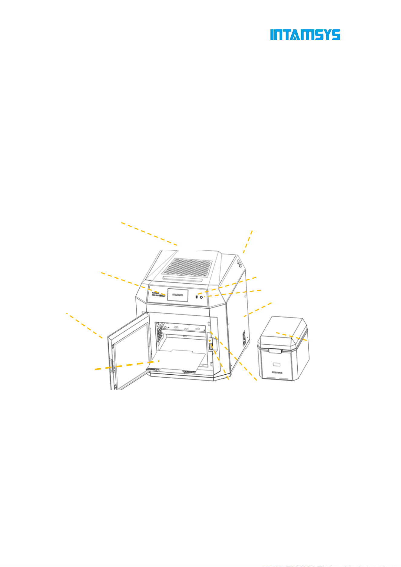
The visible parts of the printer are shown in the following figure:
The right side plate, left side plate and rear side plate of the housing are removable for
access to internal components; the top door and front door must be closed during printing
and locked by electromagnetic locks.
1. Product Appearance
Fig. 3.1 Front View of Printer
Top Door
USB Port
Glass Door
Buildplate
Electromagnetic Lock
Filament Tube Ports
ON/OFF Button
Touch Screen
Front Door Sensor
Power Plug Port& Power Switch
Independent Filament Box

12
Fig. 3.2 Rear View of Printer
3.2 Top Door and User Operation Interface
Push the top door upward to observe the movement of extruder from above and for the
maintenance of XY rack and print head assembly.
By releasing the electromagnetic lock through screen operation, the top door can be
pushed upward and supported by damping hinges. The damping hinge can ensure that the
top door stops at any opening or closing position.
Below the top door is the user interaction area, which includes touch screen, USB port and
ON/OFF button.
Users can control the print part and obtain the machine status information through the
touch screen. The USB port is used to insert the U-disk to print and software and firmware.
The ON/OFF button is used for startup and shutdown, as well as emergency shutdown.
Fig. 3.3 Schematic Diagram of User Operation Area
ON/OFF Button
USB Port
Touch Screen
Top Door Handle
Air Outlet
Fan Inlets
Back Panel
Left Side Panel
Panel Screws

13
Fig. 3.4 Schematic Diagram of Top Door Opening
3.3 Printing Chamber Components
The front door can be pulled open from the right side by the release of the electromagnetic
suction of the front door through screen operation, and then it can be seen that the printing
chamber contains front door, hotbed, double extruder assembly, electromagnetic suction,
magnetic suction and door sensor.
When the printing chamber is heated, its stainless steel Build Plate and side plates are hot.
Please do not touch them to avoid scalding.
The four leveling knobs under the hotbed can be used to manually level the printing
platform.
Fig. 3.5 Schematic Diagram of Front Door Opening Mode
Fig. 3.6 Printing Chamber
Front
Door Handle Position
Damping Hinge
Extruder Assembly
Front Door Sensor
Hotbed Printing Platform
Front Door Electromagnetic
Front Door Magnet
Front Door

14
3.4 Print Head Assembly
The print head assembly is used to melt the filament and form a desired model on the
printing buildplate in combination with the movement of X-axis, Y-axis and Z-axis. A
machine contains two separate print heads, generally the left extruder for printing model
material and the right extruder for printing support material. Generally, there's only one
extruder performing printing at the same time point, while the other extruder stands by at
the end of X-axis. When copying or mirror printing is carried out, the two extruders move
simultaneously.
Refer to Chapter 4 for loading and unloading of materials.
Fig. 3.7 Extruder Assembly
3.5 X-axis and Y-axis Components
X-axis and Y-axis components drive the double-extruder to move within the XY plane
according to commands.
X-axis and Y-axis are driven by the synchronous belts, whose tension has been properly
adjusted at factory and does not need to be re-adjusted during use. After a period of use,
if the printing quality is found to have degraded significantly, the likely cause is the
synchronous belts becoming loose due to various reasons. In this case, remove the left
and right lateral plates of the printer and check the tension of the left and right synchronous
belts of Y-axis; After removing the rear housing, you can adjust the tension of the Y-axis
synchronous belt. Open the top door to see and check the tension of the synchronous belt
of X-axis. If the tension of a synchronous belt is found too small, you can increase the
tension using the method shown in the figure below. The left and right synchronous belts
of Y-axis shall keep a consistent tension.

15
Fig. 3.8 X-axis and Y-axis Components
Y-Axis Motor
Y-Axis Synchronous Belt
X-Axis Synchronous Belt
Y-Axis Bellows
X-Axis Motor
X-Axis Bellows

16
Fig. 3.9 Tension Adjustment of Y-axis Synchronous Belt

17
Fig. 3.10 Tension Adjustment of X-axis Synchronous Belt
3.6 Z-axis Components
The Z-axis components drive the hotbed to move up and down. Remove the back lateral
plate to maintain the Z-axis components when necessary.
The trigger plate of the photoelectric sensor is already in place and generally does not
need to be adjusted by the user. Only when problems are encountered with manual leveling
of the hotbed may it be necessary for the user to check and adjust the trigger plate position
appropriately. Adjusting the trigger plate of the photoelectric sensor upward enables the
zero position of the hotbed to move downward, and adjusting the trigger plate of the

18
photoelectric sensor downward enables the zero position of the hotbed to move upward.
Fig. 3.11 Z-axis Components
3.7 Hotbed Components
The hotbed components consist of printing build plate, high-temperature resistant
magnet, leveling sensor, coaming and heating film. The printing build plate of the printer
is a magnetic build plate, and 18 high-temperature resistant magnets are installed on the
hotbed substrate, which can adsorb the printing build plate to the hotbed substrate in a
flat and firm manner. Four leveling sensors are installed at the bottom of the hotbed to
sense the distance between the nozzle and hotbed for automatic leveling. At the same
time, the hotbed substrate has four leveling screws. Manually level these screws
according to the guidance of the operation interface when necessary.
Synchronous Pulley
Z-Axis Motor
Synchronous Belt
Ball Screw
Power Switch
Guide Shaft X2
Linear Bearing X2
Sensor Trigger Plate
Mainboard
Photoelectric Sensor x2
Handle of Printing
Buildplate
Heating Film
Coaming
Magnetic Hotbed Substrate
High-temperature
Resistant Magnet
Printing Buildplate
19
Fig. 3.12 Hotbed Components
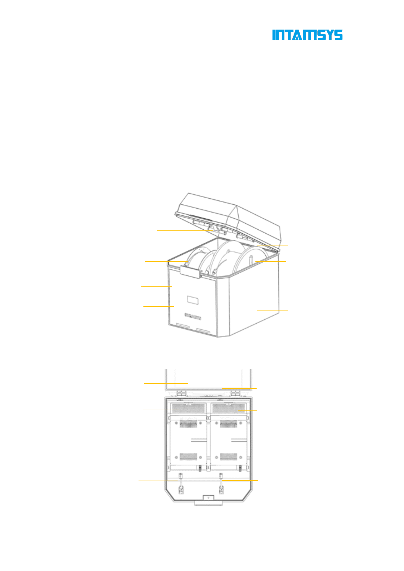
3.8 Independent Filament Box
The printer is supplied with an Independent filament box (INTAMBox) that can hold up to
two rolls of 1 kg material. Seal rings and buckles are provided around the filament box to
ensure its sealing performance. The filament box is supplied with a drying box filled with
4A molecular sieve desiccant, which can ensure the low humidity environment inside the
filament box. The upper cover of the filament box is equipped with a charging tray tension
device to ensure that the printing wire rod will not be loosen during printing and that the
wire coil will not topple when the wire rod in the wire coil is used up. Please refer to the
Operation Manual of INTAMBox for details.
Fig. 3.13 Schematic Diagram of Independent Filament Box
Fig. 3.14 Top View of Independent Filament Box
Upper cover
Temperature and humidity
indicator
Lower cover
Charging tray tension device
Printing wire rod
Buckle
Seal ring
Quick connector x2
Drying box
Bearing x8
Feeding pipe plug x2
Rotating shaft x4
Handle

20
4 User Interface
4.1 Overview
This chapter describes the main user interface (UI) of FUNMAT PRO 310 APOLLO. For
the specific printer operation information and programs, you can refer to Chapter 5. The
printer must be powered on before using the touch screen.
FUNMAT PRO 310 APOLLO user interface consists of a touch screen located in the
middle of the front side of the printer. The main interface of the touch screen includes
three main functional areas: status bar, navigation bar and display area.
Fig. 4.1 Overview of User Interface
The status bar is docked to the top of the touch screen display. On the status bar, in
addition to viewing Wi-Fi, U-disk and network status, you can also view alarm information.
The navigation bar is on the right side of the panel, where you can access main functions
through corresponding commands.
In the display area, you can select the G-code file to be printed, start/pause/stop printing,
and preview the printing status on the model picture.
4.1.1 Status Bar
The status bar is docked to the top of the touch screen display and appears on each
page of the user interface. It displays various information including network status
indicators and USB flash memory.
Wi-Fi
Connection
Wired Network
Connection
Remote
Print
Mouse
U-disk
Keyboard
Error Alarm
System Time

21
Fig. 4.2 Status Bar
4.1.2 Navigation Bar
Fig. 4.3 Navigation Bar
You can perform the following operations through the navigation bar on the screen.
Homepage: Printing operation, preheating and heat preservation settings, model graphic
progress display, real-time status display, etc.
Queue: You can manage G-code/print file import and print order, and engineers can
manage their daily work tasks in the queue.
Material: You can carry out material selection, loading and unloading, material database
management and other materials-related operations in this interface.
Tools: In this interface, you can control each moving axis of the printer and nozzle
extrusion operation, as well as print calibration and parameter setting related operations.
Settings: You can view system parameters and make relevant system settings.
4.1.3 Display Area
The display area displays the related information corresponding to the selected function
module, including operation buttons, texts, images, or schematic GIF, etc.
After the machine is powered on and started, it will automatically enter the main interface.
When you select a function button in the navigation bar, the display area switches to the
corresponding interface.
If there is no screen operation for 10 minutes, the system will automatically call the

22
Screen Saver (the screen protecting time can be set in the Settings interface). Touch the
screen again to return to the main interface.
Fig. 4.4 Screensaver Interface
4.2 Main Interface
The homepage interface mainly displays the overall information of the device during
printing. The left area includes model print progress preview and print operation buttons,
which are used to start/pause/stop printing.
The real-time temperature status of the printer is displayed in the right area, including
heat preservation time, L-nozzle temperature, R-nozzle temperature, chamber
temperature and hotbed temperature.
The current connection status of the device is displayed by the icon on the top. If an error
alarm occurs during printing, it will also be displayed in this bar.
Touch the screen to view and operate other functions displayed on the main interface.

23
Fig. 4.5 Main Interface
4.2.1 Load Print Files
FUNMAT PRO 310 APOLLO provides two methods to load :USB and Local Storage.
Click to select the file acquisition method, and find the print file by reading USB
storage or printer local storage. Files sent remotely through FTP and slice software can
be viewed in the local storage. You can choose to click "Print" to load the print file for
immediate printing, or click "Add to Queue" to load the file into the queue for subsequent
printing.
Fig. 4.6 Storage Mode
The print file format can be .gcode or .ifp. For .ifp format file. You can preview the model
shape and the print progress can be displayed during printing.

24
Fig. 4.7 Loading Print Files
4.2.2 Main Status Area
The main status area can display model pictures and show print progress by filling color.
The model is completely filled to indicate that the print job is complete. If the model
cannot be displayed, the system will display a default image. The file name and materials
required for printing are displayed below the model picture.
Fig. 4.8 Print Preview Interface
There are two shortcut buttons in the upper right corner that let you lock and unlock the
front door and top door and view details related to print files.
Fig. 4.9 Details Interface
4.2.3 Auxiliary Status Area
The auxiliary status area displays the temperature of L-Nozzle, R-Nozzle, chamber and

25
hotbed. The current temperature is displayed on the left, and the target temperature is
displayed on the right. The arrow icon and fill color animation indicate the progress of
heating/cooling, and it will be fully filled with the color if the target temperature is reached.
The loaded material is displayed on the right side of the nozzle temperature, and you can
quickly know the model number of the material installed in the material box.
Fig. 4.10 Auxiliary Status Bar
In order to obtain better printing quality, you can click the heat preservation time and set
the preheating stabilization time of the chamber before printing and the heat preservation
maintenance time of the chamber after printing. You can also disable it or adjust its
duration as needed.
Fig. 4.11 Preheating and Heat Preservation Settings
4.2.4 Control Area
The bottom control area includes "Open" , "Start" and "Stop" buttons as well

26
as a progress bar to control or check the printing progress.
Click the "Open" button and enter the "File Navigation" interface to open the file.
The Start/Pause/Stop buttons are available during the printing phase.
Task progress and consumed/remaining time are shown on the progress bar.
When the print task is completed, a command to reprint or perform the next task in the
queue will be displayed.
Fig. 4.12 Print Control
4.3 Queue
It includes current jobs and history jobs.
In the current jobs , import and edit commands are provided in the upper right corner. You
can add jobs or adjust the order of jobs.
Fig. 4.13Current Jobs

27
Once the current jobs is completed in the queue, the next job will be automatically listed .
Fig. 4.14 Editing Current Jobs
The History Jobs module features management functions at its bottom section. Users
may browse details of past jobs, reprint existing historical jobs, or remove any records
that are no longer required.
Fig. 4.15 History Jobs
4.4 Material
You can carry out material setting, material loading and unloading, and material database
management on the material interface.

28
Fig. 4.16 Material Interface
4.4.1 Material Selection
Pressing the material name list button will display INTAMSYS materials and user-defined
materials. Materials that were used recently and frequently will be displayed at the top,
where you can scroll down to select all available materials.
User-defined materials can be configured in the material database.
Fig. 4.17 Material Selection Interface
Specifically, if the material on the printer is inconsistent with the material settings in the
G-code print file, it will alert the user to apply the material. Press "Apply to Nozzle", and
the printer will automatically recognize and apply the correct material to the L-Nozzle and
R-Nozzle.

29
Fig. 4.18 Proofreading Print Materials
4.4.2 Material Loading
After preparing required materials, correctly select the name of the required materials in
the material interface, and click the "Load" button. Verify that the selected material is
correct, then click "Continue Loading". Follow the on-screen prompts to complete the
preparation steps and click "Next", the nozzle will automatically heat up to the target
temperature and start loading material. If a manual loading material is selected, follow the
operation prompts to finish loading manually.
Click the "Back" button to exit the loading process.
At the final step, click "Reload" to repeat the above procedure.
Fig. 4.19 Material Loading Interface

30
Fig. 4.20 Material Loading Process
Fig. 4.21 Material Loading Process
Fig. 4.22 Material Loading Process
4.4.3 Material Unloading
The material unloading process is similar to loading. Press the "Unload" button and
unload the filament step by step according to the wizard tips.
NOTE: First feed and then unload the filament to prevent the materials in the nozzle from

31
carbonizing.
Fig. 4.23 Material Unloading Interface
Fig. 4.24 Material Unloading Process
Fig. 4.25 Material Unloading Process

32
4.4.4 Supply Material after Out-of-material Alarm
The printer provides the out-of-material alarm function. When the filament runs out, the
printer will pause while an alarm code prompting you to change the material will pop up on
the screen.
Fig. 4.26 Out-of-material Alarm Interface
Click the "Supply Filament" button on the screen, and then change the material according
to the prompts on the screen. The procedure is as follows:
1. Unload old filament with reference to section 4.4.3 "Material Unloading".
2. Load new filament with reference to section 4.4.2 "Material Loading".
3. After the filament is loaded, click the "Print" button on the screen to continue printing.
4.4.5 Material Database Management
Press "Material Database" in the upper right corner of the material interface to enter the
material database to view the details of built-in material attributes. The built-in material
attributes of INTAMSYS cannot be modified or deleted, but its copy can be generated by
clicking . After parameter modification and setting are completed, the new material
process parameters will be stored in the user-defined materials.

33
Fig. 4.27 Material Database
Fig. 4.28 Material Process Parameters
Note: These material process parameters are only used for printer operations except
formal printing. Such operations include material loading, material unloading, leveling, XY
calibration, preheating, and heat preservation, etc. During formal printing, the printer will
run the parameters of the loaded G-code command file, instead of the user-defined preset
parameters in the printer.
In the user-defined interface, you can click to create a new material print process.
Enter corresponding parameters and click
"Confirm" to save.

34
Fig. 4.29 New Material
Click to modify, copy or delete the existing material process parameters, and click
"Confirm" to save the above operations.
Fig. 4.30 User-defined Material Database
Click in the user-defined interface to export existing printing process parameters
or import external parameters. Select the path to save or read parameters. It facilitates
parameter transplantation.

35
Fig. 4.31 Modification of User-defined Material Database
4.4.6 Drying and humidity
The real-time temperature and humidity of the current filament box are displayed at the
bottom of the Material Interface. You can click the to enter the Drying and
Humidity Interface.
Fig. 4.32 Temperature and Humidity on the Material Interface
On the Drying and Humidity Interface, the left side displays real-time temperature and
humidity data; The right side features the hot air drying function. Select the material, and
the system will automatically match the recommended hot air drying temperature. You can
also manually modify the target temperature by clicking the ; the hot air
drying function can be turned on or off via the control panel.

36
Figure 4.33 Drying and Humidity
4.5 Tools
The Tools page is divided into four functional modules: Axis, Calibration, Tune and Replace
Nozzle. In the Axis interface, you can adjust the positions of the nozzle and hotbed. In the
Calibration interface, you can perform printing buildplate leveling and XY offset. In the Tune
interface, you can adjust the parameters during printing. Replace Nozzle can be performed
by following the operating steps.
Fig. 4.34 Tools Interface
4.5.1 Axis
The Axis Control Interface allows manual adjustment of the positions of the moving
platform and nozzles, as well as control over material extrusion from the nozzle. Adjust
the settings according to the component to be operated—you can modify the movement
step length, and click Home to reset the corresponding component to its initial
position.You can also directly enter the absolute position value in the input field to move
the component.

37
Axis Control Interface:
Fig. 4.35 Axis Control Interface
4.5.2 Calibration
Click the "Calibration" button in the Tools interface to enter the Calibration Interface.
The Calibration Interface consists of four steps:
Manual Leveling: Manually level the print bed.
Auto Leveling: Use a pressure sensor to automatically detect the distance between the
nozzle and the buildplate , as well as the flatness of the buildplate at different positions.
Position compensation will be performed during the printing process.
Nozzle XY Offset: Compensate for the nozzle XY offset by printing a standard sample.
Manual Left/Right Nozzle Z-Offset: Manually compensate for the Z-axis offset.
Fig. 4.36 Calibration Interface
You can choose to perform any one or several of these steps. When the printer is used for
the first time, the calibration steps must be carried out in sequence. The following table
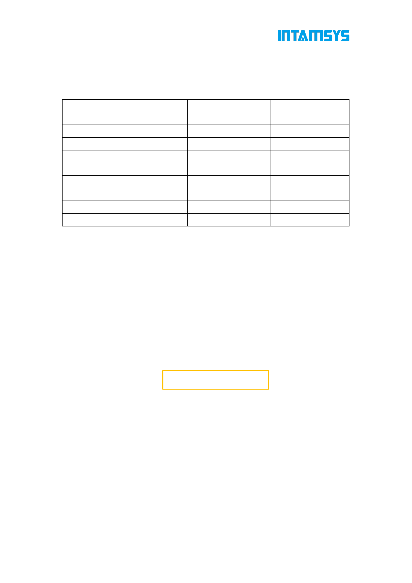
38
guides you on how to selectively perform the steps after different operations. (● indicates
this step is required, while
— indicates this step is not required.)
Conditions
Step 1:
Leveling
Step 2:
Nozzle XY offset
After replacement of L-Nozzle ● ●
After replacement of R-Nozzle ● ●
After replacing with a new print head
assembly
● ●
After replacing with a new printing
buildplate
● —
Leveling error ● —
Nozzle XY Offset error — ●
Table 6.1 Conditions for Leveling and Nozzle XY Offset
4.5.2.1 Manual Calibration of Printing Platform Leveling
For manual leveling, measure 4 points on the platform through a feeler gauge (thickness:
0.2 mm), while rotating the screws under the printing platform through an M8 screwdriver
to keep the distance between nozzle tips of the 4 points and the hotbed platform consistent,
so that the overall XY motion plane is parallel to the hotbed platform. Manual leveling is
achieved only by the left nozzle.
1. After automatic leveling fails, enter the manual leveling interface as guided, or click
"Manual Leveling" in the Calibration interface and operate according to the pop-up prompts.
Fig. 4.37 Manual Leveling Access

39
Fig. 4.38 Preparation for Manual Leveling
2. First tighten the screws counterclockwise one by one to slightly lower the hotbed.
Fig. 4.39 Manual Leveling Step 1
3. Adjust the first screw in the left front corner, measure the distance between the nozzle
and the printing platform with a feeler gauge (thickness: 0.2 mm), pull the feeler gauge
back and forth until it just passes through, and then click the "Next" button;

40
Fig. 4.40 Manual Leveling Step 2
4. After adjusting the 4 points on the platform for the first time in the same way, check "I
have done it", and then click "Next" to repeat the leveling;
Fig. 4.41 Manual Leveling Step 3

41
Fig. 4.42 Manual Leveling Step 4
5. After the second manual leveling, a Complete button pops up on the screen. Click it
to lower the platform to the bottom of Z-axis, and then return. Manual leveling ends.
Fig. 4.43 End of Manual Leveling
Note:
During the installation of the printing buildplate before leveling, it shall be
correctly adsorbed on the platform along the guide grooves on both sides
of the platform base plate;
Clean the residual materials on the nozzle tip before leveling;
Clean the printing platform before leveling; no foreign matters shall be left;
Before leveling, clean the chamber to avoid collision with foreign matters
when the platform descends.
4.5.2.2 Calibration of Automatic Printing Platform Leveling
1. the chamber temperature will automatically drop below 60°C. Then, follow the

42
prompts to check the interface checkbox "I have done it" and proceed to the next
step.
图 4.44 Auto Leveling Prepare
2. The nozzle and buildplate will automatically heat up to the temperature required for
the material.
Fig. 4.45 Heating the Nozzle
3. Once the nozzle temperature is reached, the left nozzle will move to the proper
position for material extrusion; after extrusion is completed, the left nozzle will cool
down automatically, followed by an automatic nozzle cleaning process upon cooling
completion.
4. After the left nozzle completes its procedure, the right nozzle will move to the proper
position for material extrusion; upon extrusion completion, the right nozzle will cool
down automatically and then undergo an automatic nozzle cleaning process once
cooling is finished.

43
5. Once the cleaning of both left and right nozzles and the heating-up of the buildplate
are completed, the system will automatically switch to the Auto 100-Point Leveling
Interface and start the leveling process automatically.
Fig.4.46 10*10 point leveling interface
6. The nozzles start the 100-point leveling test. The printer automatically performs
multi-point leveling and records the progress of each leveling step; the left nozzle
first levels the 90 points on the left side, and then switches to the right nozzle to level
the 10 points on the right side.
Fig.4.47 10*10 point leveling interface
7. Upon completion of the leveling process, a 2D visualization will be automatically
generated based on the leveling results. If leveling is successful, click "next" to start
printing. During the printing process, the system will automatically perform Z-axis
position compensation for the platform according to the nozzle movement.

44
Fig. 4.48 Completion of 100-Point Leveling
Fig. 4.49 100-Point Leveling Successful
Note:
During the installation of the printing build plate before leveling, it shall be correctly
adsorbed on the platform along the guide grooves on both sides of the platform
base plate;
Clean the residual materials on the nozzle tip before leveling;
Clean the printing platform before leveling; no foreign matters shall be left;
Clean the chamber before leveling to prevent the platform being lowered from
colliding with foreign matters;
The screen displays the maximum and minimum values of all measuring points for leveling
on the right side. When the difference between the maximum and minimum values is over
0.5 mm, leveling failure is prompted to request you to perform manual leveling as guided
in the figure (refer to section 4.6.6). After manual leveling, return to this interface to perform
automatic leveling again.

45
Fig. 4.50 100-Point Leveling Failed
If automatic leveling exits and an alarm is given due to sensor failure during leveling, it is
recommended to first perform manual leveling (refer to section 4.6.6), then manually
conduct nozzle Z offset(refer to section 4.6.7), and finally disable the automatic leveling
function in More Settings of the Settings interface before printing.
Fig. 4.51 Manual Leveling Calibration
4.5.2.3 Nozzle XY Offset
After automatic leveling or manual leveling and nozzle Z offset, start to conduct nozzle XY
offset. Following the steps below, the machine reads XY offset of the L&R Nozzle through
a printed scale for compensation during printing. Follow the prompts on the screen to
complete the operation in turn.
1. Select nozzle XY Offset.

46
Fig. 4.52 Nozzle XY Offset Interface
2. Make pre-calibration preparations as prompted.
Fig. 4.53 Pre-calibration Preparation
3. Wait for the left and right nozzles and hotbed to be heated to the target
temperature in sequence.

47
Fig. 4.54 Heating Nozzles
4. Start to print the calibration model, namely the scale.
Fig. 4.55 Printing the Scale
5. After printing the scale, take out the printing Build Plate to read the scale to obtain
X offset value and Y offset value respectively, and click "+"/"-" buttons to enter
values.
Fig. 4.56 Modifying L&R Nozzle XY Offset
The scale shall be read as follows:
① Read the scale of the model printed by the right extruder based on the model printed
by the left extruder;
② First, read the X offset value to check whether the center line of the model printed by
the right extruder is to the left or right of the center line of the model printed by the left
extruder. Use the "-" value for the left and the "+" value for the right;
③ Then, read the Y offset value to check whether the center line of the model printed by
the right extruder is above or below the center line of the model printed by the left extruder.
Use the "-" value for below and the "+" value for above.
④ Find the scale line where the two models are most aligned, then count from the center
line to this scale line and record the value as N.

48
⑤ Enter the "N" value into the input box.
For example, the figure below shows the scales printed during an XY offset. The X offset
value shall be "+6" and the Y offset value shall be "-5".
Fig. 4.57 Reading Method of XY Offset Scale
Note: The offset value 1 represents a scale, an actual deviation of 0.05 mm.
If it is found that the center lines for the horizontal or vertical print scale range are far apart
and other scale lines are difficult to coincide with each other after reading the print scales,
it means that the XY deviation has exceeded the measurable scale range (the maximum
scale range is 15, that is, the deviation is 0.75mm). Take the following steps:
① First determine the offset direction "-"/"+" by observing the position of the center line
of the model printed by the right extruder relative to the center line of the model printed by
the left extruder.
② Set the offset to the maximum value, and click the "OK" button.
③ Perform XY offset again, print and test the models until a determined offset is read.
4.5.2.4 Manual L&R Nozzle Z Offset
Test and manually calibrate the L&R Nozzle Z Offset through a 0.2 mm-thick feeler gauge.
1. Prepare a 0.2 mm-thick feeler gauge to ensure that the hotbed platform is tightened
without residual materials. The chamber will automatically cool down to below 60°C.
Fig. 4.58 Preparation for L&R Nozzle Z Offset

49
2. After waiting for the left and right nozzles and hotbed platform to be heated to an
appropriate temperature, clean up the materials adhered to the nozzles with an
accompanying brush, and click "I have done it".
Fig. 4.59 Waiting for Heating Interface
3. Measure the distance between the nozzle and the printing platform with a feeler gauge
(thickness: 0.2 mm), pull the feeler gauge back and forth until it just passes through, adjust
the distance on the screen so that the nozzles rise or drop, and then click "Calibrate" button.
Fig. 4.60 L-nozzle Z Offset
4. After the L-Nozzle offset is completed, calibrate the R-Nozzle with the same method.

50
Fig. 4.61 R-nozzle Z Offset
5. The offset value of the heights of the left and right extruders is displayed in a pop-up
window. Click "OK" to end Z-axis offset.
Fig. 4.62 End of L&R Nozzle Z offset
4.5.3 Tune
During the printing process, the following parameters of the printer can be adjusted on
the Tune Interface: left nozzle temperature, right nozzle temperature, buildplate
temperature, chamber temperature, left fan speed and right fan speed.
The specific parameter setting steps are as follows:
1. Click the icon of the parameter to be adjusted to highlight it.
2. Change the parameter value by clicking the "-"/"+" buttons below or sliding the slider
bar, the target value will be displayed in the box.
3. Click the "Apply" button to complete the parameter settings.

51
4. Click the "Reset" button to revert to the previous settings.
Fig. 4.63 Parameter Settings Interface
4.5.4 Replace Nozzle
You may choose to replace the nozzle and proceed to the nozzle replacement process,
following the prompts to operate:
1. Please select the nozzle to be replaced.
Fig. 4.64 replace nozzle
2. If there is still material left in the nozzle, click the "Go to unload" button first and follow
the prompts to remove the material.
3. Click "Replace"; the nozzle will automatically heat up to the extrusion temperature,
and both the nozzle and the heated bed will move to the appropriate position.

52
Fig. 4.65 nozzle heating
4. The nozzle temperature is reached, the process will automatically proceed to the
nozzle removal and installation step. Follow the prompts to operate: use tweezers to take
out the hot nozzle from the sleeve, replace it with a new one, and install the new nozzle
onto the print head.
Fig. 4.66 disassemble and install the nozzle
5. After replacing the nozzle, click "Done, to Calibration" to re-perform the auto leveling
and XY offset calibration.
4.6 Settings
The Settings interface is used for relevant settings of the system, including device
information viewing, software update, networking setting and printer system parameter
settings, etc.

53
Fig. 4.67 Settings Interface
4.6.1 Device Information
You can set the printer on this page, including:
Machine Name: Set the printer name with alphabetic characters, special characters,
and numeric characters (ASCII code).
Remote Print: Set the remote print mode
Command Line: Input the control device through command line
Storage Available: Display the available memory of the current machine.
Restart: The device automatically restarts.
Software Version: The current software version number is displayed. If an update is
needed, click to access the software version details page and perform the update.
Firmware Version: The current firmware version number is displayed. If an update is
needed, click to access the firmware version details page and perform the update.
3kg Box Firmware Version: Displays the current firmware version number of the 3kg
Box .
OS Version: Display the current system version number.
Print Time Statistics: Display the total print time of the current machine.
More Settings: Including LED brightness adjustment, screen brightness adjustment,
screensaver time, language switching, Date & Time setting, motor and material
detection enable (Wi-Fi auto reconnect, auto leveling enable, Motor enable. door
detection enable, reset factory settings, Ethernet as Default Route)

54
Fig. 4.68 More Settings
4.6.2 Remote Print
In the Device Information interface, click the "Remote Print" button to enable remote print,
and connect the printer to the computer through the IP address to support remote sending
and print of G-code files. (Refer to section 5.4.3.2 for details)
Fig. 4.69 Remote Print Settings

55
Fig. 4.70 Remote Print enabled
4.6.3 Camera Settings
Set the camera parameters, and you can preview the video here.
Fig. 4.71 Camera Settings
4.6.4 Motor Enable
The "Motor Enable" switch is used to enable/disable X-axis motor, Y-axis motor, Z-axis
motor, extruder motor, auxiliary feeding motor, etc.
Click "More Settings" in the Settings interface, and then click the button on the right side
of the "Motor Enable" to turn it On/Off. Blue indicates "On".
"On" means that all motors are powered on and "Off" means that all motors are powered
off. After it is disabled, you can push each motor to move freely for easy maintenance.

56
Fig. 4.72 Motor Control Interface
4.6.5 Screen save time
Click "More Settings" under the Settings interface, and then click "Screen save time" to set
the automatic screen save time to 10 min to 30 min in a step of 10 min.
Fig. 4.73 Automatic Screensaver Time Settings Enabling Option
4.6.6 Wi-Fi Settings
Wi-Fi connection can be enabled for the printer.
Click "Settings" to enter the wireless network interface, and enable/disable it through the
button on the right side of WLAN. Blue indicates that it is enabled. Wi-Fi connection can
be enabled or disabled in the WLAN interface, which displays the Wi-Fi list on the left side.
It can be automatically refreshed or refreshed after the user slides the screen. On the left
side, select the Wi-Fi that can be connected and enter the password to connect with it. The
device can automatically record the password and access the Internet.

57
Enable DHCP mode, click the "Apply" button, and the machine automatically acquires the
unmodifiable IP address and other contents. To manually modify the IP address and other
contents, manually disable the DHCP mode to enter the manual setting mode, modify them,
and click the "Apply" button to apply them.
You can configure other Wi-Fi settings. After restart, the printer will automatically reconnect
to the last Wi-Fi hotspot (on the premise that the following options are enabled: Settings
Interface > More Settings > Wi-Fi Auto Reconnect.
Fig. 4.74 Wi-Fi Settings
4.6.7 Wired Network Settings
The printer can be connected to the Internet through a network cable. Click "Set IP" at the
bottom left to complete the basic settings.
Enable DHCP mode, click the "Apply" button, and the machine automatically acquires the
unmodifiable IP address and other contents. To manually modify the IP address and other
contents, manually disable the DHCP mode to enter the manual setting mode, modify them,
and click the "Apply" button to apply them.

58
Fig. 4.75 Wired Network Settings
4.7 Other Interfaces
4.7.1 Warning Prompt
The warning information icon can be displayed in the status bar at the top of the
main interface. You can click to view the error code, and handle it according to the
description and prompt operations to clear the warning.
Fig. 4.76 Warning Prompt
You can view previous alarm messages of the last day, last three days or last week.

59
Fig. 4.77 Alarm Statistics
4.7.2 Resuming Print
If you get some error messages during printing, indicating that print can be resumed. You
can operate by simply following the steps in the wizard.
4.7.3 Command Line
Command line refers to the mode in which the printer is open to developers. It is mainly
used for debugging and fault diagnosis of the printer and does not need to be enabled
during normal printing. In command line, the printer can be controlled and fault diagnosis
can be conducted by sending G-code.
You can enter "Command Line" through Settings interface.
Fig. 4.78 Command Line Interface
60
5 Operating the Printer
This chapter describes the basic operational steps for operating FUNMAT PRO 310
APOLLO.
5.1 Startup and Shutdown of Device
5.1.1 Power on the Printer
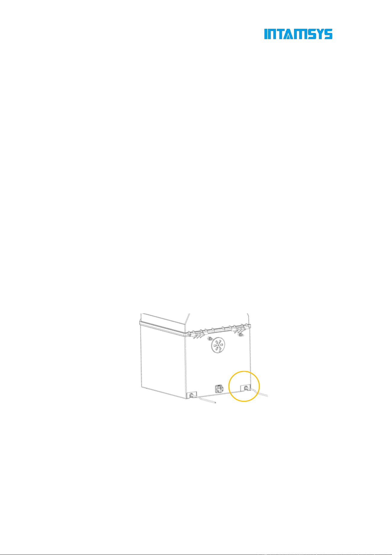
1. The power socket is located on the lower right side of the machine. Connect the two
ends of the power cord to the AC power supply plug (printer voltage: 110V and 220V) and
the power socket of the printer, respectively;
2. Insert the power plug, then switch the power switch next to the power socket of the
printer to the (I) position;
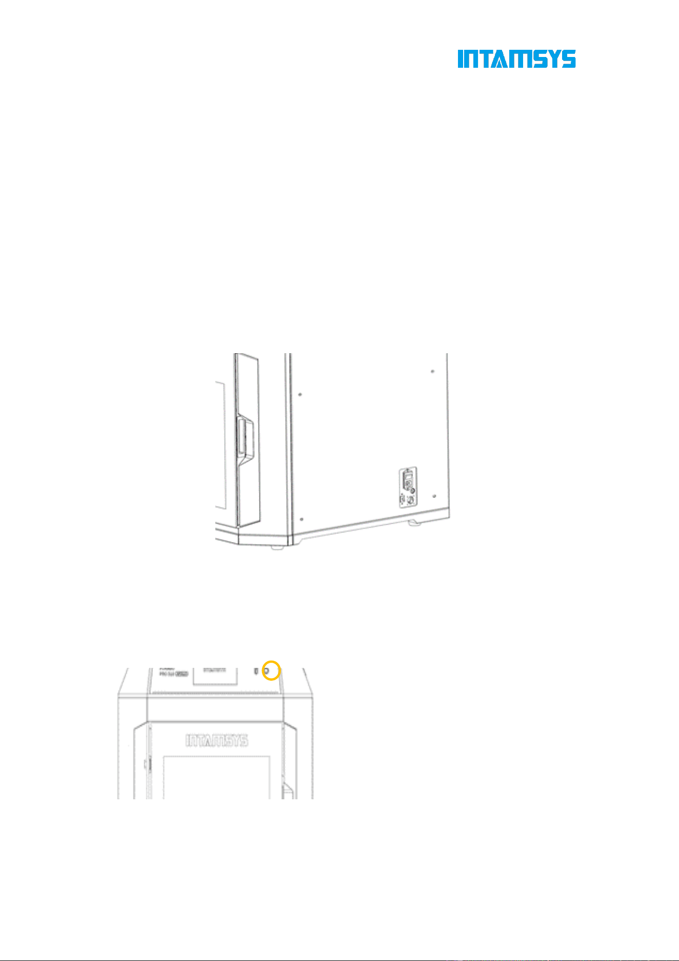
Fig. 5.1 Printer Power Supply Port and Switch
3. Turn on the front ON/OFF button on the right side of the screen in the front of the printer,
and the button indicator is on. At the same time, operate the screen to enter the start
interface, and the printer starts.
Fig. 5.2 Start/Stop Botton and Startup Interface
61
5.1.2 Power off the Printer
Press the power switch (which is also used to turn on the printer) on the front side of the
printer. Note: This operation is only to turn off the printer. To power off the printer, the power
switch must be switched to the (O) position.
Note: If the printer is not in use for a long time, disconnect the power cord from the
AC power supply socket.
5.2 Preparation of Print Materials
This section guides you on how to load filaments into nozzles. When completing the
required steps, be sure to follow the operation prompts displayed on the touch screen.
The printer is supplied with an independent filament box (INTAMBox) that can hold up to
two rolls of 1 kg material. The left compartment is used for printing by the left extruder,
mainly for model materials, and the right compartment is used for printing by the right
extruder, mainly for supporting materials.
Note: Make sure that there are no print parts or other debris on the printing platform when
loading or unloading filaments. Because the X-axis, Y-axis, and Z-axis will be reset during
this operation, and any print parts or other debris on the printing platform can collide with
the extruder or X beam.
1. The filament box is placed on the right side of the printer, as shown in the figure. Insert
one end of the feeding pipe in the accompanying accessories of the filament box into
the quick connector and the other end into the quick connector located on the right side
of the printer. The feeding pipe should be inserted to the bottom for smooth feeding.
Fig. 5.3 Schematic Diagram for Installation of Feeding Pipe
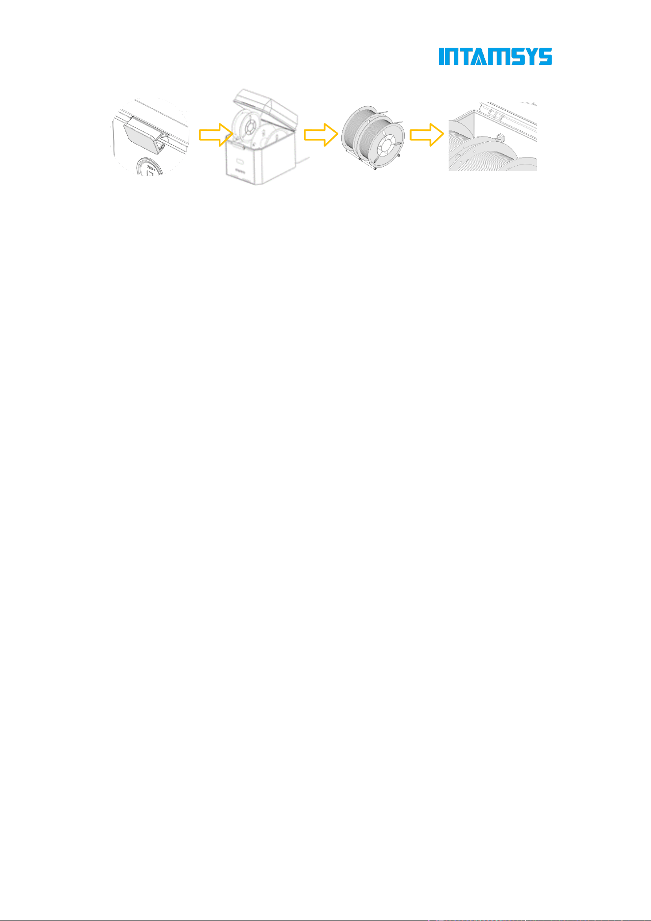
2. Unbuckle the upper cover of the filament box, place the drying box in the front slot of
the filament box, put the wire rod on the roller of the filament box as shown in the
figure, and then thread the wire rod through the quick connector at the rear end until
the material protrudes from the feeding pipe of the printer. After manual loading is
completed, buckle the upper cover.
62
Fig. 5.4 Schematic Diagram of Wire Rod Loading
3. Click the "Material" button on the screen operation interface, click the left or right wire
coil icon to select the extruder to be loaded with materials. The highlighted icon
indicates the extruder is activated;
Fig. 5.5 Material Interface
4. Pressing the "Material Database" button will display INTAMSYS materials and user-
defined materials. Materials used recently and frequently will be at the top, where you
can scroll down to select available materials. User-defined materials can be configured
in the material database.

63
Fig. 5.6 Material Database Interface
Specifically, if the material on the printer is inconsistent with the material settings in the G-
code print file, the system will alert the user to check the material. Click "Apply". Then the
material will be automatically applied to the L&R Nozzle.
Fig. 5.7 Extruder Temperature Settings Interface
5. After selecting the material, press the Load button to load the filament step by step
according to the load process.
Prepare the filament according to the prompts;
The nozzle will automatically feed the material once it heats up to the target
temperature.
The user can click the "Back" button to exit the feeding process;
Fig. 5.8 Material Loading Interface

64
Fig. 5.9 Material Loading Process
Fig. 5.10 Material Loading Process
Fig. 5.11 Material Loading Process
Please refer to section 4.4 "Material" for operations such as material unloading, material
process template modification and material database modification.
5.3 Nozzle Replacement or Material Change
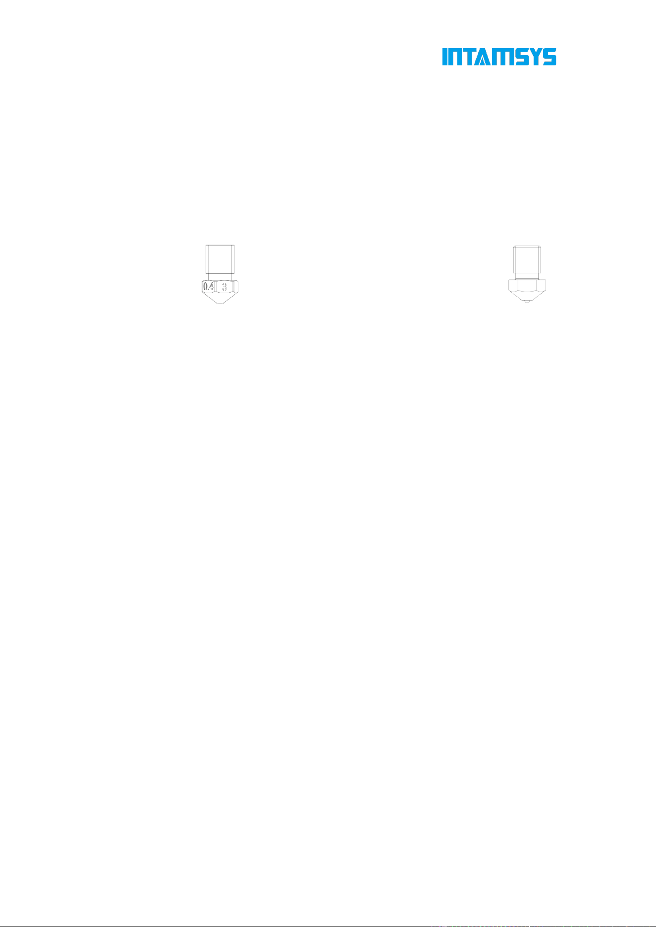
There are two types of printing nozzles: The integrated silver-white nozzle is made of
65
CuCrZr and can print all materials except fiber-containing materials (PA6-CF/PA12-CF,
etc.), such as ABS+, ABS-HS, ASA, HIPS, PA6/66, PC, PC/ABS, PC-FR, PC-PBT, PLA,
PVA, SP3030, TPU-95A, PETG, PPS; the combined silver-white nozzle is mainly made of
CuCrZr and high-hardened steel at the tip and mainly prints fiber-containing materials,
such as PA6-CF/PA12-CFPET-CF, PET-GF, PPA-CF/GF, PPS-CF/GF, SP3050, and
SP5010.
It is strongly recommended that one nozzle prints only one material, which is
conducive to stable operation of the device and easy management.
a) Integrated Nozzle b) Combined Nozzle
Fig. 5.12 Schematic Diagram of Nozzle Structure
5.3.1 Replace the Nozzle
The procedure of nozzle replacement is as follows:
1. On the main interface, click "Tools" to enter the tools interface, then select Nozzle
Replacement to start the process.You may choose to replace the nozzle and proceed to
the nozzle replacement process, following the prompts to operate:
2. Please select the nozzle to be replaced.
Fig. 5.13 replace nozzle
3. If there is still material left in the nozzle, click the "Go to unload" button first and follow
the prompts to remove the material.
4. Click "Replace"; the nozzle will automatically heat up to the extrusion temperature,
and both the nozzle and the heated bed will move to the appropriate position.

66
Fig. 5.14 nozzle heating
5. The nozzle temperature is reached, the process will automatically proceed to the
nozzle removal and installation step. Follow the prompts to operate: use tweezers to take
out the hot nozzle from the sleeve, replace it with a new one, and install the new nozzle
onto the print head.
Fig. 5.15 disassemble and install the nozzle
6. After replacing the nozzle, click "Done, to Calibration" to re-perform the auto leveling
and XY offset calibration.
5.3.2 Change Material before Printing
To change material type before printing, you shall not only change the material on the
Material interface, but also selectively replace the printing nozzle. Different nozzles shall
be used to print different materials. If you want to use one nozzle to print different materials,
the nozzle temperatures for printing of such materials must be very close, and an extrusion
temperature difference of no more than 50℃ is recommended.

67
Note: Do not use nozzles for printing overhigh melting point materials to print low melting
point materials. For example, printing PLA with nozzles that have already printed PC will
cause blockage of the extruder and printing failure.
If the old and new material types are consistent or the nozzle temperatures for printing
of different materials are close, it is not necessary to replace the nozzle. The procedure
is as follows:
1. Unload the old material.
2. Select the new material to be loaded, and preform the loading operations.
If the old and new material types are inconsistent or there is a big difference between
the nozzle temperatures for printing of different materials, the nozzles shall be
replaced; accordingly, leveling and XY offset shall also be done. The procedure is as
follows:
1. Unload the old material.
2. Replace the nozzle.
3. Select the new material to be loaded, and preform the loading operations.
4. Perform again the step of hotbed leveling and XY offset.
5.3.3 Pause to Change Material
If you need to change material while the printer is printing, follow these procedures:
1. Click the "Pause" button at the bottom of the main interface and wait until the movement
of the extruder stops completely.
2. Unload the old material.
3. Load the new material.
4. After the material is loaded, click the "Start" button on the lower part of the interface to
continue printing.

68
Fig. 5.16 Interface of Pausing to Change Material
5.4 Basic Printing and Prototyping Operations
5.4.1 Prepare the Printer
Prepare the printer for prototyping:
1. Power on the printer (refer to section 5.1.1 for details);
2. Use an extruder brush to remove materials left on the extruder;
3. Clean the residues or impurities on the printing Build Plate and magnetic platform base
plate;
4. Place the printing buildplate on the platform base plate along the left and right guide
grooves of the magnetic platform base plate;
Note: The magnetic platform base plate has a large suction force. When placing, hold the
printing platform handle tightly with both hands, tilt the printing buildplate, let it to contact
the magnetic base plate on the rear side first, and then slowly lay it on the platform by
magnetic attraction to avoid hand pinching.
69
Fig. 5.10 Installing the Printing Platform Buildplate
5. Load materials according to the print task requirements.
6. Perform leveling and extruder XY offset. This step can be skipped if leveling and
calibration have been done.
7. When ready, the printer can perform print tasks formally.
5.4.2 File Slicing
If G-code is unavailable, you can slice the file using INTAMSUITE NEO. If G-code is
available, skip this step.
1. Download: Through the official website at https://www.intamsys.cn/ download the
slicing software INTAMSUITE NEO.
.
2. Import Model: Create a new project and import the model in the format
of .stl, .step, .obj, .x3d, .oltp, .stp, .iges, or other intermediate CAD files.
Fig. 5.17 Import Model
3. Model operation: Right-click "Arrange All Models" to arrange all models automatically
and move them to the center of the printing platform.

70
Fig. 5.18 Model Operation
4. Print settings: Select the printer model (select FUNAMT PRO 310 APOLLO here), and
click the "Print Mode" command to select the print mode. FUNAMT PRO 310 APOLLO
provides mirror print and duplicate print.
Fig. 5.19 Print Settings
Select the material and nozzle diameter required for the print head. For double-head print,
switch to the extruder 02, after selecting the material for the extruder 01, proper supporting
material can be automatically recommended for selection.

71
Fig. 5.20 Extruder Material Settings
The slicing software is pre-configured with various print profile templates, which can be
selected as required, with the required process parameters adjusted in the detailed settings
dialog box before slicing.

72
Fig. 5.21 Process Parameter Settings
5. Print preview: Wait for slicing to be completed. After the operation is done, you can
preview the slicing results by clicking "Preview" to view the print path and direction on
each layer. You can even simulate the whole print process after checking the material
color, line type, feeding speed, temperature, fan speed, and layer thickness in detail.

73
Fig. 5.22 Previewing the Print Results
6. File saving: When you are satisfied with the previewed slicing results and save the
print file to your defined location, the software will save g-code or ifp print file for direct
remote print. You can also save it in the U-disk and later insert the disk to the printer
for selective file printing or send it to the printer remotely. Refer to the following text
for the operation mode.
Note: As the naming format for .gcode file is imported into the U-disk, names with
Chinese characters or special characters are not supported for now.
For more detailed function operation of the slicing software, refer to:
https://help.intamsys.com/en/home/INTAMSUITE_NEO/New_User_Guide
5.4.3 Import the Print File to the Printer
5.4.3.1 Insert the U-disk for Printing
1. Select the location of the print file. Select the location where the file is stored in the
drop-down bar in the upper right corner of the screen, such as USB storage or local storage
(for remote print).
Fig. 5.23 Selecting File Storage Location
2. Click the Open icon in the lower left corner of the screen, and the print file list will pop
up;

74
Fig. 5.24 Print File Interface
3. Select the print file, and click the "Print" button to load the print file. You can also select
"Add to Queue" to add print files to the print queue. If you import the file through U-disk,
after the print file is loaded, you can pull the U-disk out of the USB port without affecting
the printing.
Fig. 5.25 Print File Loading Completion
5.4.3.2 Remote Print
In the device information interface, click the "Remote Print" button to enable remote print
and select the IP address on this page. You can view the log after connection.

75
Fig. 5.26 Remote Print Settings
Click "Remote Print Enabled", click the "IP Address", and select the IP address for remote
connection of the device. The remote connection password will be displayed on the right
side. Click "Refresh" to randomly change the remote connection password. When the
"Server State" is displayed as "ON", the device has remotely connected for remote print.
Fig. 5.27 Enabling and Setting Remote Print
There are three modes for remote operation. Before remote print, make sure that both the
printer and computer work on the same LAN and the printer is remotely connected with the
computer through IP address.
1. FTP transfer mode:
(1) Enter the IP address of the printer's remote client in the local Windows folder.

76
Fig. 5.28 FTP Transfer Settings for Remote Transfer
(2) Enter "root" as the username and "intamsys" as the password in the prompted
dialog box to log in to the printer.
Fig. 5.29 FTP Password Login for Remote Transfer
(3) Import the file to be printed to the .gcode folder, and the printer receives the
uploaded file and prints the local file selected on its screen.
Fig. 5.30 Remote File Transfer Interface
2. Remote print with INTAMSUITE NEO
(1) Install and open the computer software INTAMSUITE NEO
.
(2) In the toolbar interface, select "Print".

77
Fig. 5.31 Print Interface
(3) Click "Add Printer". You may either type IP address or click the "Search &
Select" button to search for the IP address.
Fig. 5.32 Adding the Printer
(4) Select SFTP or FTP. Enter the IP address and remote connection password of
the current printer, and click "Connect" to create a connection.

78
Fig. 5.33 Remote Connection through IP Address
(5) Click "Upload File", and you may select files from local storage or slicing
software.
Fig. 5.34 Uploading or Synchronizing the File
(6) Click "Get to Print" to directly print the file on the slicing software or on the
printer as it would also receive the print file.
Fig. 5.35 Remote Print Interface
(7) Start the G-code print task remotely, and the display screen of the printer will
enter the print interface accordingly. For other remote operations, the screen
interface will also display corresponding actions.

79
Fig. 5.36 Print File Loading Completion Interface
3. INTAMSUITE Local Print
Besides application in INTAMSUITE NEO, remote print can also be independently applied
after starting the program named INTAMSUITE Local Print (installed together with
INTAMSUITE NEO).
The INTAMSUITE Local Print tool is not disturbed by many slicing-related functions. It has
a user-friendly interface for ease of operation.
Install the INTAMSUITE Local Print tool and connect it to the printer
through the IP address. You only need to select the print file to print in the same operation
mode as that for remote print with INTAMSUITE NEO. For detailed steps, refer to:
https://help.intamsys.com/en/home/INTAMSUITE_NEO/Remote_Print
Fig. 5.37 Interface of Adding INTAMSUITE Local Print to the Printer

80
5.4.4 Printing and Prototyping Process
5.4.4.1 Main Printing and Prototyping Process
Click the "Start" button on the screen to start printing and prototyping. If remote print is
conducted through INTAMSUITE NEO or INTAMSUITE Local Print, manual operation is
not required. The printing and prototyping process has three steps: "preheat - print - heat
preservation":
1. Preheat. Preheat the printing platform and the chamber before printing. The
preheating temperature and time are the platform temperature, chamber
temperature and preheating time of the material in the left extruder on the printer
(it is necessary to confirm whether the material setting of the material interface is
consistent with G-code). When the platform temperature and chamber
temperature reach the target values, preheating timer starts;
2. Print. After the preheating time lapses, the printer starts to read the G-code file to
perform formal printing.
3. Preserve the heat. After printing, the nozzle cools down and the printing platform
and chamber shall maintain heated. The heat preservation temperature and time
are based on the platform heat preservation temperature, chamber heat
preservation temperature and heat preservation time of the material in the left
extruder.
5.4.4.2 Modification of Preheating Time and Heat Preservation Time
During the printing and prototyping process, you can modify the preheating time and heat
preservation time.
1. Click the "Heat Preservation Time" button on the right side of the main interface to
display the modification interface of preheating time and heat preservation time.
2. You can enable or disable "Heat Hold" and "Maintain" options.
3. Modify the time by clicking "-"/"+", and click the "OK" button to save the modification.
Note: Preheating and heat preservation need to be set before printing, and the settings
during printing will not take effect; preheating can only be disabled or preheating time can
be reduced when the heat preservation of chamber has been maintained for a long time,
otherwise it will affect the next printing effect.

81
Fig. 5.38 Preheating and Heat Preservation Interface
5.4.5 Duplicate/Mirror Print
FUNMAT PRO 310 APOLLO supports single-extruder print/regular dual-extruder
print/duplicate print/mirror print.
Single-extruder print: Perform printing with an extruder at a time.
Regular dual-extruder print: Perform printing with two extruders in turn, one for model
printing and the other for auxiliary structure or support.
Duplicate print: It means that a printer with dual independent extruders can print two
models with identical dimensions, angle, and direction at the same time during 3D printing
to improve the production efficiency. Copy print is very useful for the mass production of
the same components or objects, significantly improving efficiency. Copy operation only
needs to be performed for the existing model in the slicing software.
Fig. 5.39 Duplicate Print
Mirror print: It means that a printer with dual independent extruders can print two
symmetrical models at the same time during 3D printing. Through mirror print, the re-design
of a symmetrical model can be avoided, and mirror operation only needs to be performed
for the existing model in the slicing software.

82
Fig. 5.40 Mirror Print
The duplicate/mirror print is as follows:
1. Import the model file and select duplicate/mirror print.
Fig. 5.41 Duplicate/Mirror Print
2. According to individual print requirements, set the print parameters such as extruder
and process template for the model, and preview slicing.
Fig. 5.42 Previewing the Print Results
3. Transfer the sliced file to the machine which shall meet the following conditions at this
point:
(1) Ensure the same print materials or similar process parameters for dual left and
right extruders for duplicate/mirror print.
(2) Perform manual calibration of L&R nozzle Z offset before copy/mirror print.
If the difference between the left extruder offset and the right extruder offset is less than or

83
equal to 0.2 mm, it means that the printer can directly perform duplicate print or mirror print;
however if it is greater than 0.2 mm, you need to manually adjust L&R nozzle height and
manually calibrate L&R nozzle Z offset, test and calibrate it with a 0.2 mm-thick feeler
gauge, and perform operations as prompted on the screen in turn with reference to 4.6.7.
Fig. 5.43 Manual Adjustment of Left and Right Extruder Offsets
Note: For mirror/duplicate print, do not disable the raft layer settings. You only need
to set mirror print in the slicing software (the raft layer is printed by default) and
directly print the required file by sending the file remotely or inserting the U-disk.
5.4.6 Continue Printing
5.4.6.1 Continue Printing after Material Shortage
When the printer detects that the printing wire rod is used up, it pauses printing and
continues printing after material reloading. This technology is very useful especially for
long-term or large-scale printing tasks as it can prevent print failure due to materials use-
up during printing, with the operation steps as follows:
Click the "Supply Filament" button on the screen, and then change the material according
to the prompts on the screen. The procedure is as follows:
1. Unload the old material.
2. Load the new material.
3. After the material is loaded, click the "Print" button on the screen to continue printing.
5.4.6.2 Continue Printing after Power Failure
In the case of power failure or other interruptions during printing, the function of continuing
printing after power failure records the printer status at the time of power failure and
prompts whether to continue printing after the device is powered on again. This technology
is particularly important for long-term important printing tasks as it can prevent print failure
due to power failure in the midway and reduce energy and material waste, with the
operation steps as follows:
1. Power on the machine after power failure during printing, and click "Clear" or "Close"
for the 406 alarm displayed in the interface.

84
Fig. 5.44 Interface 1 of Continuing Printing after Power Failure
2. The prompt window of continuing printing after power failure pops up. Click "OK", and
the machine reads the last printing progress and recovery temperature and automatically
opens and continues printing the print file before power failure; click "Cancel", and the
machine does not continue printing after power failure.
Fig. 5.45 Interface 2 of Continuing Printing after Power Failure
3. The machine starts to resume printing.

85
Fig. 5.46 Interface 3 of Continuing Printing after Power Failure
Note: Continuing printing after power failure poses the failure risk as the device is incapable
of heating to make the Build Plate temperature and chamber temperature drop quickly after
power failure and the model can be separated from the buildplate after long-term power
failure. Therefore, the function can be applied within 10 mins after power failure.
5.4.7 Pause Printing
During printing, the Pause button on the main interface is activated. The printer can
automatically pause or you can use this button to manually pause it.
5.4.7.1 Automatic Pause
1. When a red alarm is detected, the breathing light turns red and an automatic pause
command is sent.
2. The Z-axis platform is slightly lowered, then the extruder resets to the zero position, the
heating of the nozzle stops while an alarm dialog box pops up, indicating the reason for
pause.
3. You need to correct the corresponding error first, then click the "Clear" button to clear
the alarm.
4. To restore printing, press the "Start" button on the main interface, and a restoration
command will be sent to the printer to instruct it to restore printing.
5.4.7.2 Manual Pause
1. Click the "Pause" button to manually pause the printer.
2. The Z-axis platform is slightly lowered, then the extruder resets to the zero position, and
the heating of the nozzle stops.
3. To restore printing, press the "Start" button on the main interface, and a restoration
command will be sent to the printer to instruct it to restore printing.
5.4.8 Stop Prototyping
After a print task is started, the "Stop" button in the main interface is activated. The printer

86
can automatically stop or you can use this button to manually stop it:
5.4.8.1 Automatic Stop
When a red alarm is detected, the printer will automatically stop. After the printer receives
the stop command, the heating of nozzle, platform and chamber will be disabled.
5.4.8.2 Manual Stop
When the printer receives the stop command, a dialog box for confirming or canceling the
stop will pop up. Press "OK" to stop the printer. After the printer receives the stop command,
the heating of nozzle, platform and chamber will be disabled.
5.4.9 Prototyping Alarm
If the printer detects a fault that might affect the printing, a warning will be given on the
screen. The alarm status button will turn red according to the warning severity.
When you press the alarm status button, a dialog box that indicates the alarm reason will
pop up. The dialog box shows information about the alarm reason.
Fig. 5.47 Error Alarm
In some cases, the alarm will prevent your attempted start to print, and the printing will not
start until you eliminate the error. Various warnings might be displayed when the printer
performs print tasks, and some warnings will pause and stop printing. Whether the
prototyping process can be restored depends on the warning severity.
Refer to Chapter 7 for the fault alarm list and processing methods.
5.4.10 After Prototyping is Completed
After prototyping is completed, the print head resets and stops, the printing platform
automatically descends to the bottom and the screen will show 100% print progress,
indicating that the printing prototyping has been completed. The model needs to be
removed from the printer together with the Build Plate.

87
Fig. 5.48 Model Printing Completed
1. Unlock the door and open the front door of the chamber. If you want to end the heat
preservation, enter the "Stabilization time" interface and disable the Heat Preservation
option. At this time, the front door and top cover are unlocked; if you want to continue heat
preservation, click the door lock button on the status bar of the screen to unlock the front
door and top cover;
2. Wear gloves and take out the flexible printing Build Plate;
3. Bend the flexible printing buildplate up and down with both hands, and the print part will
be separated from the buildplate.
4. Remove excess supporting material from the print part.
5.4.11 Locking of Front Door and Top Door
The printer is equipped with front door electromagnetic lock and top door electromagnetic
lock. During the heating and printing process of the device, the front door and top door
shall be closed. The door will be automatically locked after it is closed. Users can click the
door lock icon on the main interface to unlock or lock the door.

88
Fig. 5.49 Door Lock Switch
For the safety of users, the printer always locks the front door and top lateral plate when
the printing starts or the chamber starts to heat, and they cannot be opened after being
locked. If you need to force unlock during this process, click the door lock button to unlock
the front door and top lateral plate.
Note: Do not put your hands into the chamber after forced unlocking to avoid being scalded
or pinched.
5.5 Printer Status
5.5.1 Temperature Status
You can view the temperature status of the printer on the main interface in real time,
including target temperature and real-time temperature of left extruder; target temperature
and real-time temperature of right extruder; target temperature and real-time temperature
of chamber; target temperature and real-time temperature of hotbed.

89
Fig. 5.50 Printer Status
5.6 Software/firmware Update
5.6.1 Update through LAN
You can update the software and firmware to the latest version through LAN to improve
your usage and printing experience.
The software/firmware is updated in the following steps:
1. Download the soft/ware/firmware package to the computer.
Software package: PRO310SW_B_Vx.x.x.tar
Firmware package: PRO310FW_Vx.x.x.bin
2. Connect the computer and printer to the same LAN through Wi-Fi or network cable.
Refer to 4.6.2 "Remote Print".
3. When the printer is "Connected", click the card title to enter the printer details page.
Fig. 5.51 Remote Connection Interface of Printer
4. Click "Update" and select "Update Software" or "Update Firmware".

90
Fig. 5.52 Software/Firmware Update Interface
5. Users confirm software/firmware update without the prompt window when the printer
is idle.
6. Select the software for update.
Fig. 5.53 Software Update Interface
7. Select the firmware for update.
Fig. 5.54 Firmware Update Interface
8. Click the "Select" button to select the file in the computer.
Software package: PRO310SW_B_Vx.x.x.tar
Firmware package: PRO310FW_Vx.x.x.bin
(Note: For the package downloaded from the Internet repeatedly, remove the
brackets behind its name to avoid update failure.
For example, modify PRO310SW_B_V1.0.4(1).tar to PRO310SW_B_V1.0.4.tar.)
Fig. 5.55 Software update Interface 1
9. Click the "Update" button, and the package file begins to be transferred. At this point,
click "Cancel" or close the prompt window, and the transfer will be interrupted.

91
Fig. 5.56 Software Update Interface 2
10. The upper machine automatically disables remote print and starts to install the
package file for update after receiving it.
Installation of package file for software update: Just wait for the upper machine to restart.
Installation of package file for firmware update: A prompt window pops up during update,
and the prompt of update completion appears in about 30 s.
Fig. 5.57 Firmware Update Succeeded
There are three prompts during firmware update:
(1) Firmware update succeeded.
(2) Firmware update failed. Please re-update it. (Update failed due to power failure
or unstable network connection during update.)
(3) Firmware package corrupted, please re-update it. (At the beginning of the update,
the update package is detected to find that the file is corrupted. Please re-
download and copy it.)
If update failed due to power failure or unstable network connection during remote update,
the software and firmware will remain the version before update and be re-updated after
the device restarts.

92
Fig. 5.58 Firmware Update Failed

93
5.6.2 Update through U-disk
Software update:
1. Decompress "PRO310SW_B_V*.tar" to get one folder (namely, "resources") and four
files (namely, "desktop", "InstallPacket.tar.gpg", "ReleaseNote.txt", and "README.txt").
2. Copy "desktop", "resources", and "InstallPacket.tar.gpg" to a U-disk, and then insert the
U-disk into the machine.
3. In the touch screen interface of FUNMAT PRO 310 APOLLO, enter the "Settings"
interface, enter the "Software Version" interface, click the "upgrade" button in the "Update
Manually" field, click the "upgrade" button in the "Software Version" field, and perform
operation as prompted step by step.
Fig. 5.59 Prompt of Software Update
Firmware update:
1. Copy PRO310FW_Vx.x.x.bin of the firmware to a U-disk, and then insert the U-disk into
the machine.
2. In the touch screen interface of FUNMAT PRO 310 APOLLO, enter the "Settings"
interface, enter the "Firmware Version" interface, click the "upgrade" button in the
"Update Manually" field, and perform operation as prompted step by step.

94
Fig. 5.60 Prompt of Firmware Update
6 Maintenance
Proper and regular maintenance not only helps to extend the service life of your printer,
but also greatly improves your printing success rate and prototyping effect every time. This
chapter describes various maintenance tasks of FUNMAT PRO 310 APOLLO that you
need to perform.
6.1 Inspection Before Each Printing
Inspection before printing ensures the safety during printing and improves the print success
rate.
6.1.1 Inspect the Printing Platform
Inspect the platform and flexible printing buildplate:
1. To ensure that the magnetic platform is free of foreign matters, there are no adsorbed
debris on the magnet, and the screws for installing the magnet are not loose or protruding;
2. To check whether there is any foreign matter or damage on the surface of flexible
printing Build Plate;
3. To correctly adsorb the printing buildplate on the printing platform.
6.1.2 Clean the Printing Chamber
The material filaments remaining on the buildplate of the chamber may melt in the heated
chamber and stick to the buildplate, and the sundries in the chamber under the platform
may occupy the movement space of Z-axis. Therefore, clean all the debris and material
chips inside the printing chamber carefully before printing.
6.1.3 Inspect the Nozzle
To prevent the residual materials on the nozzle from affecting the prototyping quality of
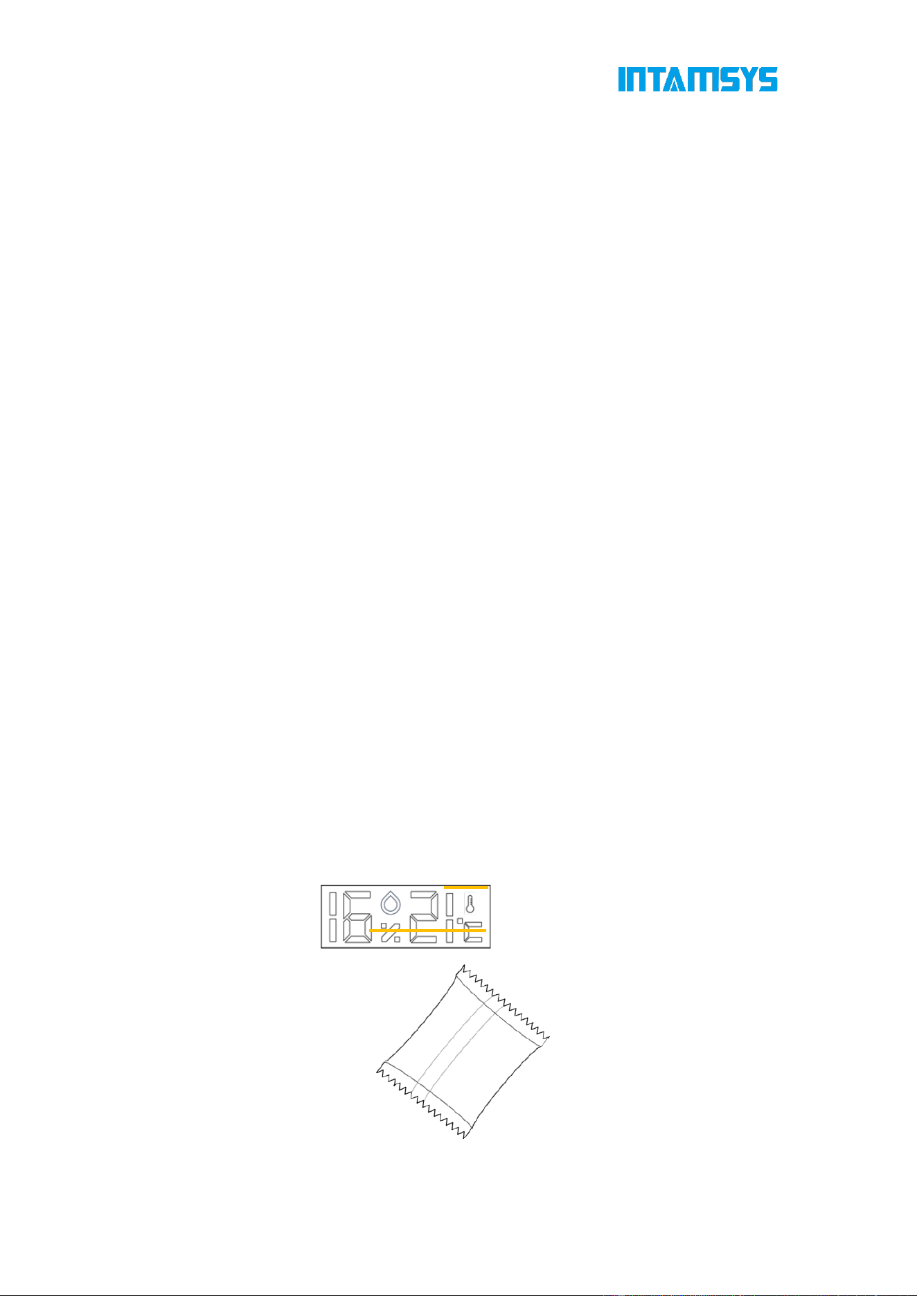
95
printing works, you should inspect whether the nozzle is clean before each printing. If it is
not clean, you need to heat the extruder to the temperature that can melt the residual
materials, then clean the extruder using a copper wire brush with wooden handle.
If the material sticks to a higher position and enters the rubber sleeve near the nozzle, you
need to remove it, clean the nozzle and then install it back.
Fig. 6.1 Cleaning the Nozzle
6.1.4 Check the Humidity of the Material Chamber
Phenomena such as stringing and bubbles occur when printing with damp materials, which
can affect the print success rate. Therefore, the humidity of the material chamber should
be checked before each print task. If the humidity in the material chamber is too high, the
molecular sieve drying box should be dried and then placed in the sealed filament box for
use.
Judging conditions: When the material box is closed for more than one day, the
temperature and humidity indicator shows that the humidity is over 20%.
Note: The filament box can play the drying role, and the wire rod shall be dried before
usage according to the Print Process Guidelines.
Fig. 6.2 Temperature and Humidity Indicator and Drying Box
Temperature
Humidity
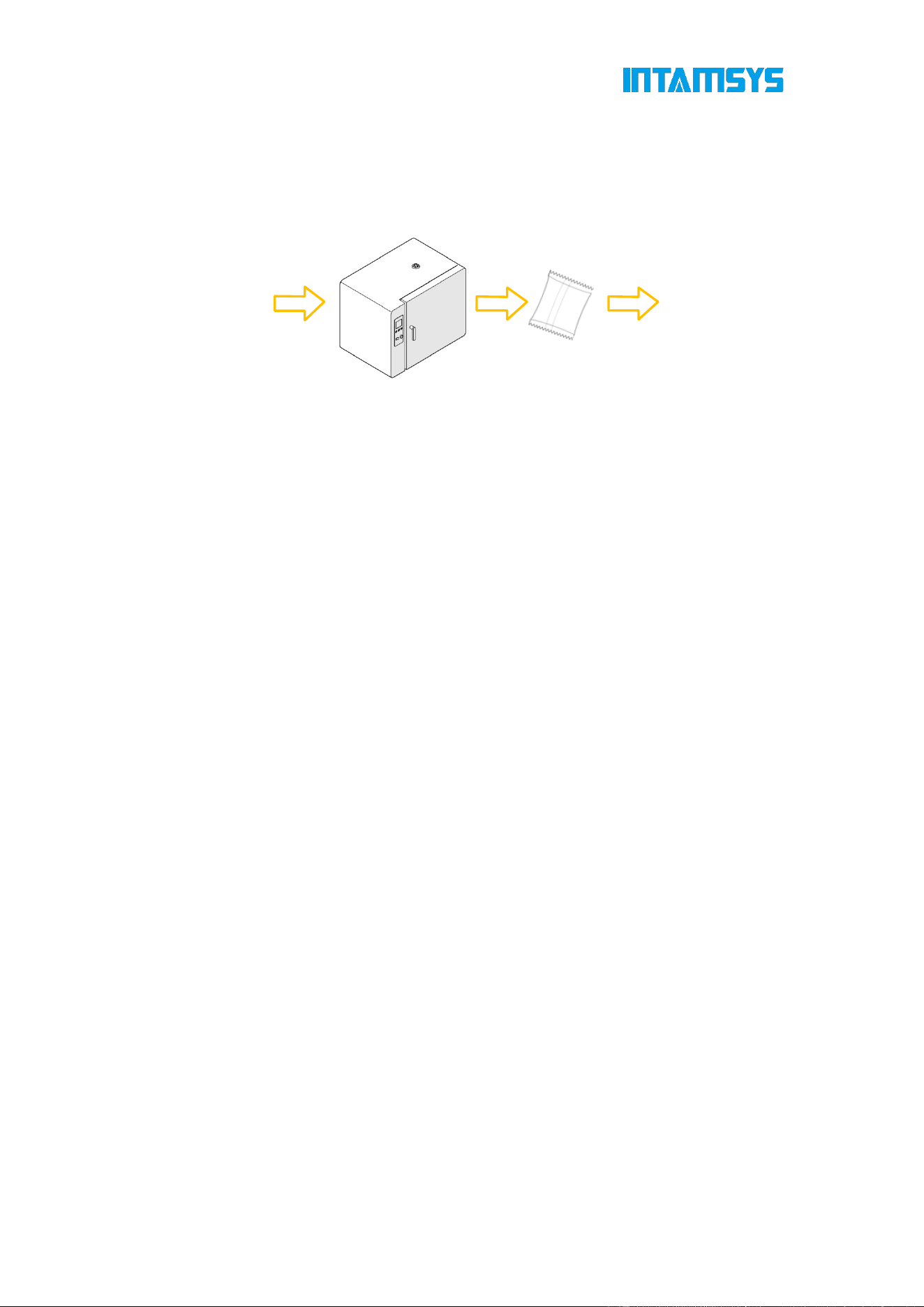
96
Drying process: Open the upper cover of the material box to take out the drying box, and
place it in the 200°C blast drying oven for drying for 2 h or a longer time; wear heat-resistant
gloves and take it out to prevent scalding, and place it in the material box after cooling
down to the normal temperature.
Fig. 6.3 Schematic Diagram of Molecular Sieve Drying Process
6.2 Maintenance after Each Printing
6.2.1 Clean the Printing Buildplate
After printing, lower the printing platform for a certain distance, then wear gloves to take
out the printing Build Plate together with the print part from the printer, bend the flexible
printing buildplate with both hands to separate the print part from the printing Build Plate,
and then clean the printing Build Plate and put it back on the hotbed.
6.2.2 Clean the Nozzle
Inspect whether the nozzle surface is stuck with some print materials after each printing. If
the nozzle is covered by residual materials for a long time, its service life will be affected.
To prepare for the next printing, pay special attention to cleanliness of the nozzle surface.
If the nozzle is stuck with too many residual materials, heat the nozzle to the set
temperature of the material and then clean it using a copper wire brush with wooden handle.
Note: Move the printing buildplate to the lowest position before cleaning the nozzle,
and be careful to avoid scald burn risk when removing the protective sleeve to clean
the nozzle.
6.2.3 Clean the Chamber
The nozzle brush scrapes some material chips into the chamber during printing. Clean the
chamber carefully every time after printing a work.
6.3 Regular Maintenance
6.3.1 Replace the Nozzle
After long term of printing, the inner and outer surfaces of the nozzle can be partially worn,
which affects the printing quality, especially for the printing of fiber-containing materials.
1. Take out the molecular
sieve drying box.
2. Place it in the 200°C oven for
drying for 2 h.
3. Cool down to the
normal temperature.
4. Place it into the central slot
of the filament box.

97
Therefore, it is recommended to pay close attention to whether the surfaces of print parts
get rough or whether there is visible wear deformation at the tip of the nozzle after 10 kg
of materials are printed with a single nozzle. If the above phenomenon occurs, it is
recommended to replace with a new nozzle.
6.3.2 Clean Feeding Gears of the Extruder
After long-term use, more and more cut material chips accumulate in the tooth spaces of
feeding gears, thus reducing the feeding force of the extruder. It is recommended to remove
the front housing of the extruder every month, remove the front cover plate, and take out
the feeding gear shaft 2 to inspect the accumulation of material chips in the tooth spaces
of two feeding gear shafts. If necessary, you need to carefully clean each tooth space with
tools such as small copper wire brush or tweezers.
Fig. 6.4 Position of Feeding Gear
6.3.3 Clean the Fans
It is recommended to clean and maintain the fan at the printer mainboard and two exhaust
fans on the upper rear side of the printer once every 12 months to prevent excessive dust
from affecting device performance.
1. Clean the two exhaust fans on the upper rear side of the printer. Remove the rear
cover of the printer, find the two exhaust fans at the upper part, and clean their blades with
cleaning tools such as brushes, non-woven fabrics, and alcohol.
2. Clean the cooling fan at the printer mainboard. Remove the rear cover of the printer.
The cooling fan is located directly below the main board. Remove four fixing screws to
slightly remove the fan (without the need to unplug the power supply), and clean its blades
with cleaning tools such as brushes, non-woven fabrics, and alcohol.
6.3.4 Maintenance of Moving Parts
It is recommended to re-apply PFPE grease or lithium soap based grease every 6 months
for the X-axis and Y-axis motion guide components (The left and right lateral plates of the
printer shall be removed when applying grease to the Y-axis guide rail).
1. Ensure that all relevant temperatures are set to "0" and the motor is disabled in System
Settings ("Motor enable" is Off);
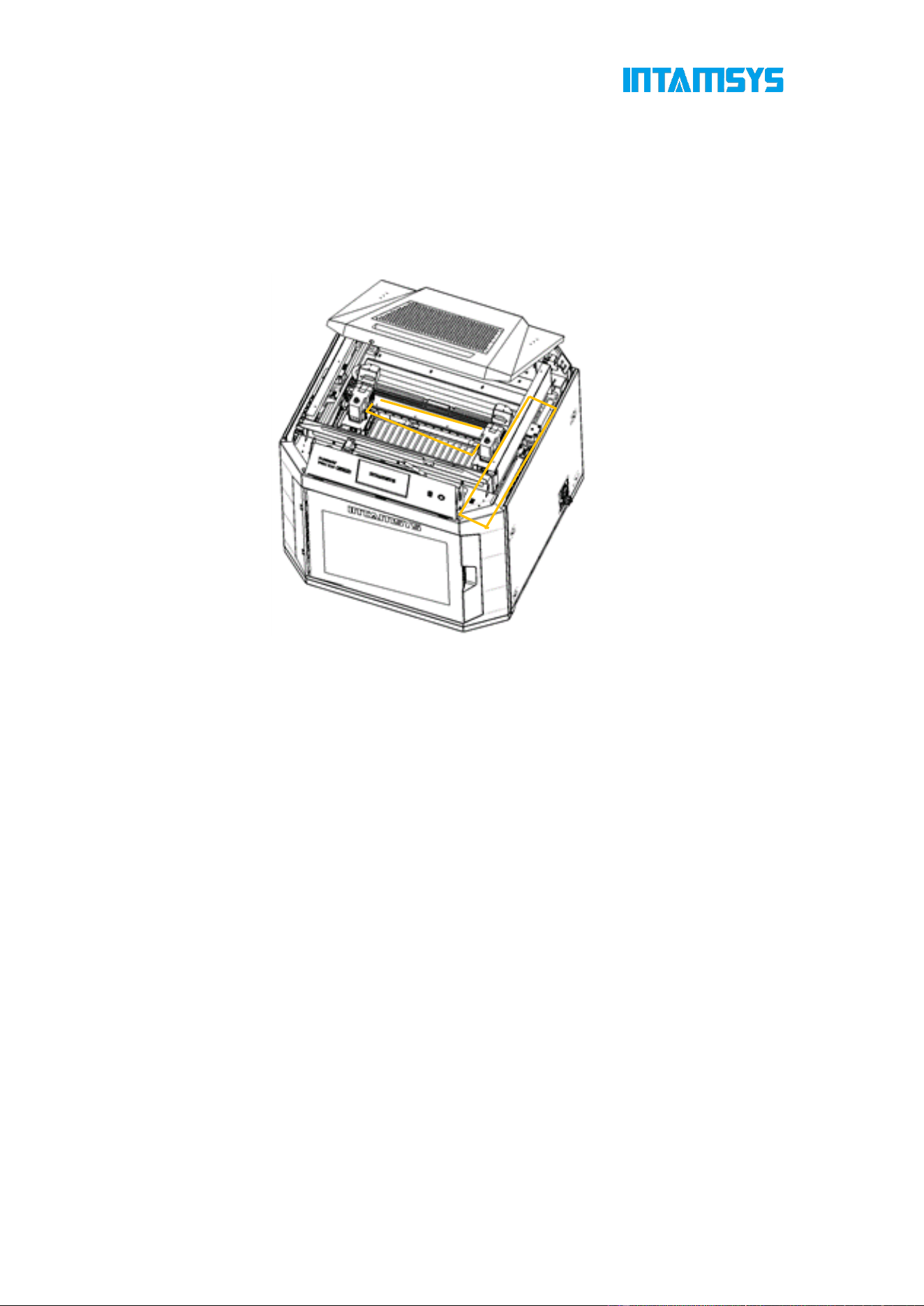
98
2. Manually move the extruder assembly to the center;
3. Clean the residual grease on the X/Y guide rail with a cloth;
4. Apply PFPE grease to the X/Y guide rail with a soft brush. Note: Excessive grease
may have a negative impact on motion.
5. Move the extruder assembly back and forth several times on the X/Y axis for evenly
applying the grease.
Fig. 6.5 Lubrication and Maintenance of X/Y Axis Linear Guide Rails
The Z-axis motion components include linear bearing and ball screw. It is recommended
to re-apply PFPE grease or lithium soap based grease to the Z-axis motion components
once every 6 months (The rear plates of the printer shall be removed).
1. Power off the printer and unplug the main power cord.
2. Remove the 4 locking screws at four corners of the rear cover with a wrench.
3. Apply PFPE grease or lithium soap based grease to the linear guide rail and ball screw
with a soft brush. Excessive grease may have a negative impact on motion.
4. Install the rear cover back to its original position and fix it, plug in the main power cord,
then turn on the printer, and move the Z-axis up and down 10 times to evenly smear the
grease.

99
Fig. 6.6 Lubrication and Maintenance of Z Axis Linear Guide Rails
Note: Before re-applying grease on each component, wipe the surface of the kinematic
pair clean with a dust-free cloth dipped in alcohol, then evenly apply grease on the surface.
6.3.5 Maintenance of Chamber Filter
Air filters are installed at the air inlets on both sides of the printing chamber. You can access
the filters by unscrewing the screws of the filter cover plate and removing the cover plate.
It is recommended to check or replace them every 6 months.
Fig. 6.7 Cleaning of Chamber Filter
6.3.6 Maintenance and Replacement of Feeding Pipe
The feeding pipe of the printer consists of two parts, one inside the printer and the other
outside the printer. The external feeding pipe is connected to the printer from an
independent filament box, and the internal feeding pipe is connected to the extruder by a
material shortage detection mechanism.
As the internal feeding pipe works in a high-temperature environment, it is recommended

100
to replace it every 12 months to avoid possible aging that may reduce its flexibility.
1. Unload the filaments and ensure that all are returned to the material compartment.
2. Turn off the printer and open the top cover, and start maintenance after the
temperature of all components drops to room temperature.
3. Move the extruder assembly to the center, press down the black collar with one hand
and take out the feeding pipe with the other.
4. Take out the other end of the feeding pipe from the quick connector according to Step
3.
Fig. 6.8 Removal of Internal Feeding Pipe
5. Remove the external feeding pipe according to the same steps.
6. Prepare new pipes of the same length, install them in place.
Note: Both ends of the feeding pipe must be fully in place to ensure smooth threading.
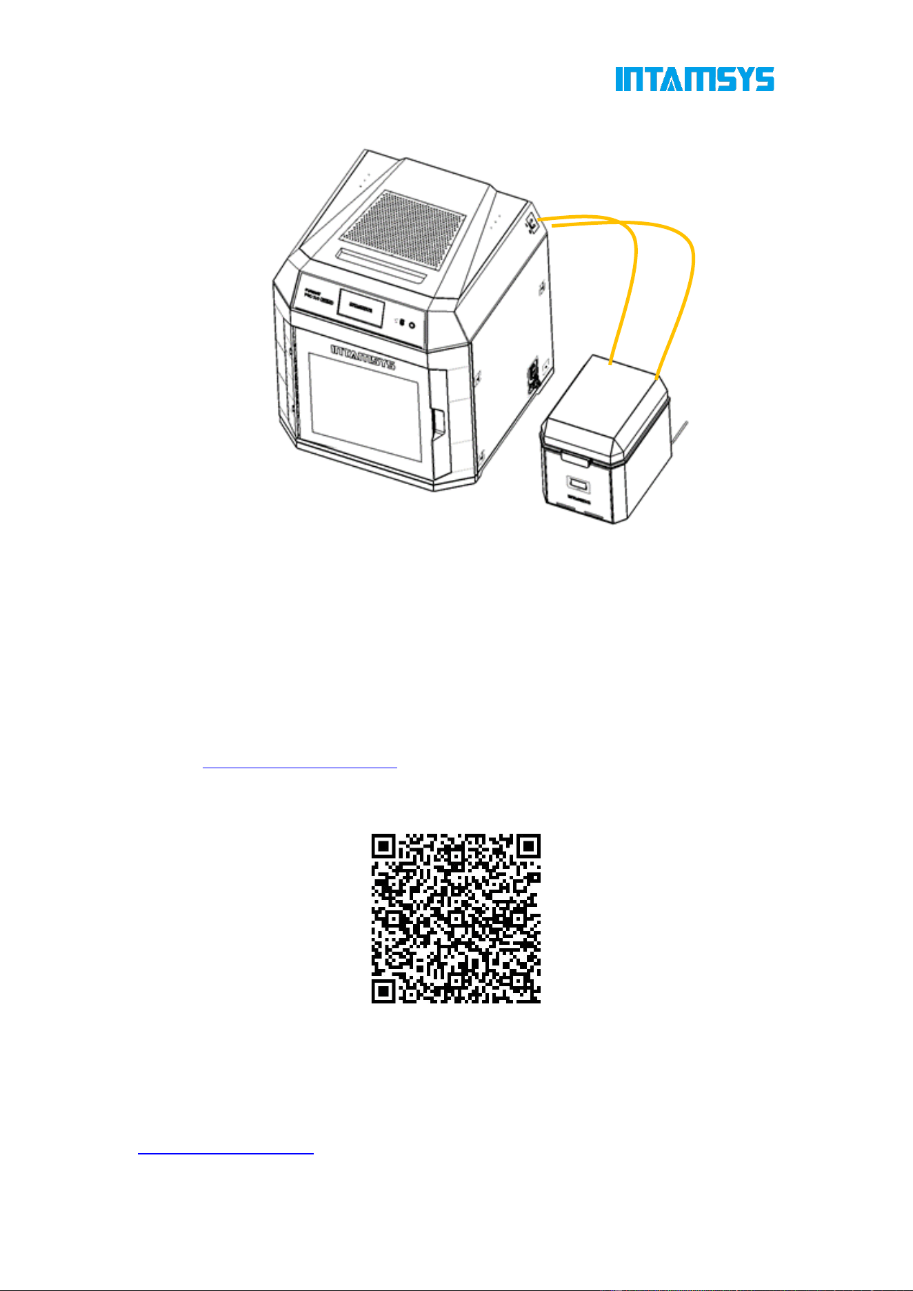
101
Fig. 6.9 Installation of New Feeding Pipe
6.4 Others
It is recommended to have a qualified professional conduct a thorough inspection of your
printer before the one-year warranty period expires. The inspection should include
checking whether the fans, heater, power supply, fuse, and other components are in normal
condition. If any issues are found, contact our local agent, refer to the INTAMSYS Help
Center:
https://help.intamsys.com/
or scan the QR code:
Some protective components might need to be removed during inspection to make the
components to be inspected observable. Be careful because these operations pose a
certain safety risk.
In addition, you can download the latest version of firmware and screen software from the
following website:
https://www.intamsys.cn/
102
7 Trouble shooting
This chapter lists some faults that might occur during printing and required troubleshooting
measures after each fault occurs.
If you have any question during operation based on this user manual, contact the Customer
Support in the region where you are located.
Table 8.1 Fault Code List
S/N Code Fault Category Measures
1 171
Serial port
communication error
error
If possible, please continue
printing. If there is no response
for a long time, please shut
down and restart the printer
2 217
Material shortage of left
extruder
warning
Please replace the material or
insert the material into the out-
of-filament detection sensor
3 218
Material shortage of right
extruder
warning
Please replace the material or
insert the material into the out-
of-filament detection sensor
4 221
Opening of chamber
front door
warning Close the front door.
5 222
Opening of chamber top
door
warning Close the top door.
6 235
Extruder leveling sensor
abnormal
warning
Extruder calibration and
automatic leveling cannot be
carried out. Please check
whether the extruder leveling
sensor is disconnected or
whether the connector is loose
7 301
Overhigh temperature of
L-Nozzle
error
Check the L-Nozzle sensor or
heater.
8 302
Overhigh temperature of
R-Nozzle
error
Check the R-Nozzle sensor or
heater.
9 303
Overhigh temperature of
hotbed
error
Check for exception in the
cable or connector of hotbed
sensor
10 304
Overhigh temperature of
chamber
error
Check for exception in the
cable or connector of chamber
sensor
11 306
Damaged circuit of L-
Nozzle temperature
sensor
error
Check the circuit of L-Nozzle
temperature sensor.
103
12 307
Damaged circuit of R-
Nozzle temperature
sensor
error
Check the circuit of R-Nozzle
temperature sensor.
13 308
Damaged circuit of
hotbed temperature
sensor
error
Check the circuit of the hotbed
temperature sensor.
14 312
Too slow temperature
rise of L-Nozzle
warning
Check whether the heater is
damaged or the wiring has
exceptions
15 313
Too slow temperature
rise of R-Nozzle
warning
Check whether the heater is
damaged or the wiring has
exceptions
16 314 Hotbed heating timeout error
For heating timeout, check for
exceptions in the heating
circuit
17 315
Chamber heating
timeout
error
For heating timeout, check for
exceptions in the heating
circuit
18 332 X-limit sensor triggered error
Please confirm whether the
printing is staggered or the
model exceeds the printing
size of the printer
19 333 Y-limit sensor triggered error
Please confirm whether the
printing is staggered or the
model exceeds the printing
size of the printer
20 334 Z-limit sensor triggered error
Please confirm whether the
leveling is normal or whether
the model exceeds the printing
size of the printer
21 391
The instruction cannot
be completed without
resetting
error
Resetting operation is required
in axis control
22 366 Motor driver alarm error Check the XYZ motor driver.
23 368 Motor drive alarm error
Check the E motor drive for
any problems.
24 369 SPI error of motor drive error
Check the E motor drive for
any problems.
25 397
Extruder temperature
update error
error
Check whether the extruder
temperature is updated.
26 398
Incorrect G-code motion
data
error
Check whether G-code motion
exceeds the maximum single
motion criterion.

104
27 406
Power-off protection
triggered by the system
for the power supply
voltage is lower than
90% of the supply
voltage
error
Continue printing after power
failure. The firmware detects
power failure during printing,
and 406 alarm will be given
after the device is powered on
again.

www.intamsys.cn
info@intamsys.com Follow us for more information
Shanghai Headquarters Germany Branch U.S. Branch
Shanghai INTAMSYS
Technology Co., Ltd.
INTAMSYS TECHNOLOGY
GmbH
INTAMSYS Technology, Inc.
Address: E11, No. 3188 Xiupu
Road, Pudong New Area,
Shanghai
Address: Zeppelinstr. 35,
73760 Ostfildern
Deutschland
Address: 11479 Valley View
Road
Eden Prairie, MN 55344
Copyright ©2024 INTAMSYS Technology. All rights reserved. The information at hand is provided
as available at the time of printing, INTAMSYS reserves the right to change any information without
updating this publication.