
I n s t a l l a t i o n
—
Maintenance
—
S e rv i c e
—
Tro u b l e s h o o t i n g
CENTURY
®
POOL & SPA MOTOR
MANUAL

1
W
elcome to A.O. Smith’s line of Century
®
Motors. This pocket manual is designed for
one purpose — to make it simple for you to
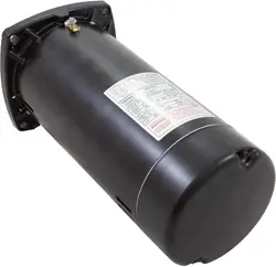
install, maintain and troubleshoot Century pool and
spa motors. Contrary to what you may be thinking just
n o w, your last name doesn’t have to be Edison in order to
p r operly service the motors shown in the following pages.
All you need are a few basic tools and some helpful hints;
the kind that appear throughout this
booklet.
We’ve included all the information we think you’ll
need to repair the most common pump motor pro b l e m s
e n c o u n t e r ed out in the field. This easy to read manual con-
tains great illustrations and diagrams for quick
re f e r ence. Assisting your customers is your job. Helping
you do that with minimum delay is our job; that’s why
we’ve pre p a red this informative manual.
INTRODUCTION

2
Replacements for every brand. Every now and then
you probably come across a motor that’s beyond re p a i r.
When you do, remember that A.O. Smith manufacture s
replacement pool and spa motors for practically every
brand you’ll ever encounter in the field. So save yourself
some time and eff o r t and just ask for Century first — at
any A.O. Smith distributor or dealer. Century motors are as
rugged as any you’ll find, but keep in mind that all motors
need service and maintenance at one time or another.
Safety first. Remember, before you begin to work on
any electrical appliance be sure to TURN OFF THE
POWER. The only time you’ll need the power on is
when you check motor voltage and amperage. If you over-
look this important guideline, someday you could unex-
pectedly get a real charge out of your work! Always play it
safe — double-check to be certain that the power is off
b e f o r e you start to work on a pool or spa motor.
If you have any suggestions or would like more
i n f o r mation about a particular subject, please write
or call:
A.O. Smith
531 North Fourth Stre e t
Tipp City, OH 45371
8 0 0 - 5 4 3 - 9 4 5 0

3
C e n t u ry Pump Motors . . . . . . . . . . . . . . . . . . . . . . . . . . . . . . . . . . . . . . . . . . . . . . . . . . . . . .5
Design Feature s. . . . . . . . . . . . . . . . . . . . . . . . . . . . . . . . . . . . . . . . . . . . . . . . . . . . . . . . . . . . . . . .7
Nameplate Inform a t i o n. . . . . . . . . . . . . . . . . . . . . . . . . . . . . . . . . . . . . . . . . . . . . . . . . . . .9
I n s t a l l a t i o n
H e a t. . . . . . . . . . . . . . . . . . . . . . . . . . . . . . . . . . . . . . . . . . . . . . . . . . . . . . . . . . . . . . . . . . . . . . . . . .1 3
M o i s t u re. . . . . . . . . . . . . . . . . . . . . . . . . . . . . . . . . . . . . . . . . . . . . . . . . . . . . . . . . . . . . . . . . . .1 4
Power Sourc e. . . . . . . . . . . . . . . . . . . . . . . . . . . . . . . . . . . . . . . . . . . . . . . . . . . . . . . . . .1 4
A l t i t u d e. . . . . . . . . . . . . . . . . . . . . . . . . . . . . . . . . . . . . . . . . . . . . . . . . . . . . . . . . . . . . . . . . . . . .1 4
M o u n t i n g. . . . . . . . . . . . . . . . . . . . . . . . . . . . . . . . . . . . . . . . . . . . . . . . . . . . . . . . . . . . . . . . . .1 4
Electrical Connections . . . . . . . . . . . . . . . . . . . . . . . . . . . . . . . . . . . . . . . . . . . . .1 5
G ro u n d i n g. . . . . . . . . . . . . . . . . . . . . . . . . . . . . . . . . . . . . . . . . . . . . . . . . . . . . . . . . . . . . . . .1 5
Wi re Size. . . . . . . . . . . . . . . . . . . . . . . . . . . . . . . . . . . . . . . . . . . . . . . . . . . . . . . . . . . . . . . . . .1 5
Wi r e Selection Guide. . . . . . . . . . . . . . . . . . . . . . . . . . . . . . . . . . . . . . . . . . . . . . . . . . . . .1 6
To o l s . . . . . . . . . . . . . . . . . . . . . . . . . . . . . . . . . . . . . . . . . . . . . . . . . . . . . . . . . . . . . . . . . . . . . . . . . . . . . . . .1 7
M a i n t e n a n c e
M o i s t u re. . . . . . . . . . . . . . . . . . . . . . . . . . . . . . . . . . . . . . . . . . . . . . . . . . . . . . . . . . . . . . . . . . .1 7
C o o l i n g. . . . . . . . . . . . . . . . . . . . . . . . . . . . . . . . . . . . . . . . . . . . . . . . . . . . . . . . . . . . . . . . . . . . .1 8
S e a s o n a l. . . . . . . . . . . . . . . . . . . . . . . . . . . . . . . . . . . . . . . . . . . . . . . . . . . . . . . . . . . . . . . . . . .1 8
C l e a n i n g. . . . . . . . . . . . . . . . . . . . . . . . . . . . . . . . . . . . . . . . . . . . . . . . . . . . . . . . . . . . . . . . . . .1 8
L u b r i c a t i o n. . . . . . . . . . . . . . . . . . . . . . . . . . . . . . . . . . . . . . . . . . . . . . . . . . . . . . . . . . . . . . .1 8
TABLE OF CONTENTS

4
Motor Troubleshooting
Motor Fails To Start (makes no sound). . . . . . . . . . . . . . . . . .1 9
Motor Fails To Start (hums, tries to start,
blows fuse or trips bre a k e r ). . . . . . . . . . . . . . . . . . . . . . . . . . . . . . . . . . . .2 0
Motor Starts But Shuts Down
(overload pro b l e m ). . . . . . . . . . . . . . . . . . . . . . . . . . . . . . . . . . . . . . . . . . . . . . . . . .2 1
Noisy Motor. . . . . . . . . . . . . . . . . . . . . . . . . . . . . . . . . . . . . . . . . . . . . . . . . . . . . . . . . . . . . . . . . . . . .2 1
Motor Hot, Smoking Or Cycling . . . . . . . . . . . . . . . . . . . . . . . . . . . . . . . . . . . .2 2
I n f o r mation Needed For Motor Replacement. . . . . . . . . . . . . .2 3
Troubleshooting A Capacitor . . . . . . . . . . . . . . . . . . . . . . . . . . . . . . . . . . . . . . . . .2 3
Best Way To Use A Vo l t - A m m e t e r. . . . . . . . . . . . . . . . . . . . . . . . . . . . . . . . .2 4
How To Replace Bearings. . . . . . . . . . . . . . . . . . . . . . . . . . . . . . . . . . . . . . . . . . . . . .2 4
S e rv i c e . . . . . . . . . . . . . . . . . . . . . . . . . . . . . . . . . . . . . . . . . . . . . . . . . . . . . . . . . . . . . . . . . . . . . . . . . . . .2 7
Wiring Diagrams’ Table of Contents. . . . . . . . . . . . . . . . . . . . . . . . . . . . .2 8
Wiring Diagrams. . . . . . . . . . . . . . . . . . . . . . . . . . . . . . . . . . . . . . . . . . . . . . . . . . . . . . .2 9 - 5 4
Date of Manufacture Ta b l e . . . . . . . . . . . . . . . . . . . . . . . . . . . . . . . . . . . . . . . . . . . .5 5
5
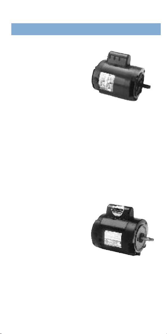
C e n t u r i o n
®
, C-flange
Switchless “1081” Motor
• Standard Eff i c i e n c y
• E-Plus, High Eff i c i e n c y
•
1
⁄
2
– 5 Hp
• No Switch, No Govern o r
• Single phase or three phase
• Suitable for operation at 50 Hz,
1.0 service factor
• Aluminum or cast iron NEMA “C” mounting brackets
• True NEMA 56-frame
• Keyed or threaded shaft
• UL standard “1081” appro v a b l e
• Full-rated and Up-rated
• 50° C Ambient
• Available as a Century two-speed motor
C e n t u r i o n
®
SE, C-flange
Switchless “1081” Motor
•
1
⁄
2
– 5 Hp
• Standard Eff i c i e n c y
• Single phase
• Aluminum NEMA “C”
mounting brackets
• 50° C Ambient
• True NEMA 56-frame
• Keyed or threaded shaft
• UL Standard “1081” appro v a b l e
• Full-rated and Up-rated
• 303 stainless steel shaft
CENTURY
®
CENTURION &
6
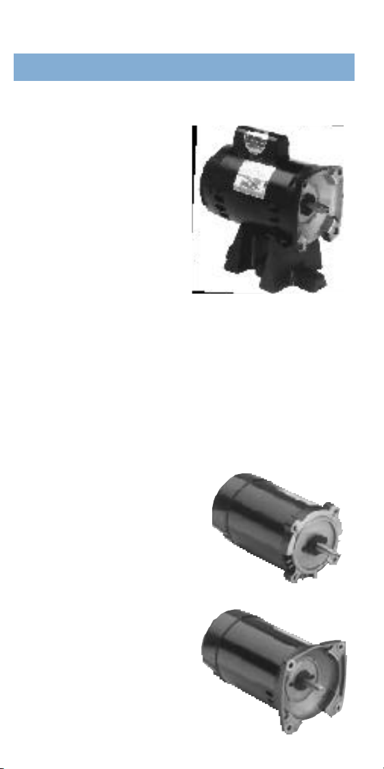
C e n t u r i o n
®
, Square Flange
Switchless “1081” Motor
• Standard Eff i c i e n c y
• E-Plus, High Eff i c i e n c y
•
1
⁄
2
– 5 Hp
• No Switch, No Govern o r
• 303 stainless steel
t h r eaded shaft
• Suitable for operation
at 50 Hz, 1.0 service factor
• Single or three phase
• True NEMA 56-frame
• UL standard “1081” appro v a b l e
• Full-rated and Up-rated
• 50° C Ambient
• Available as a
C e n t u ry two-speed motor
N e p t u n e
®,
C & Square Flange
• Standard Eff i c i e n c y
• High Eff i c i e n c y
•
1
⁄
2
– 3 Hp
• Advanced Switch Te c h n o l o g y
• 48 frame shell diameter
• 303 stainless steel threaded shaft
• UL standard “1081” appro v a b l e
• Full-rated and Up-rated
• 50° C Ambient
E-PLUS
®
MOTORS
7
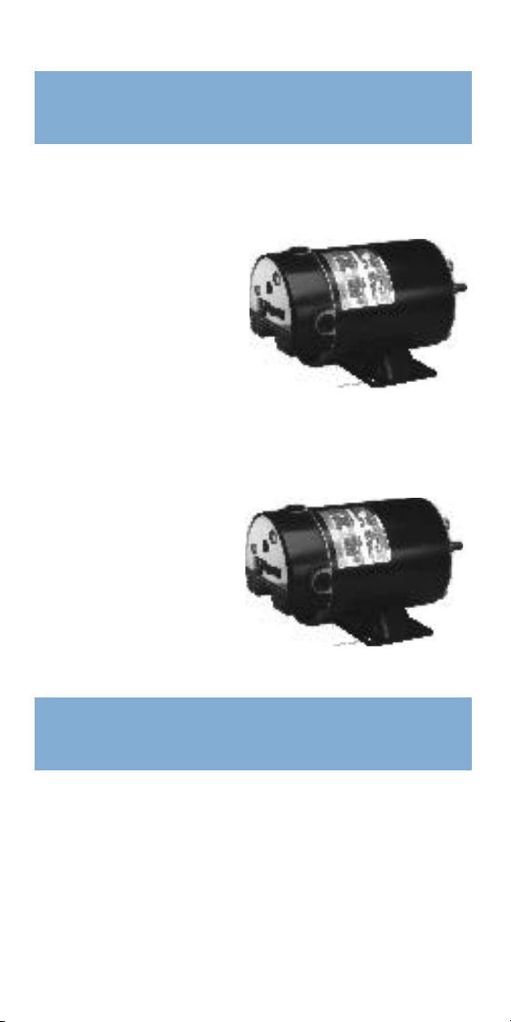
Flex-48™ Single-Speed Motors, Thru-Bolt Mount
Suitable for jetted tubs and above-ground pools and spas.
•
1
⁄
2
- 3 Hp
• 56-frame conversion base
• 3-
1
⁄
2
” shaft height
•
3
⁄
8
” threaded shaft
• Auto-reset overload
p ro t e c t i o n
• 1.0 service factor
Flex-48™ Two-Speed Low Amp Start & Run Motors
For Spas and above-ground pools, thru-bolt mount.
•
3
⁄
4
- 3 Hp
• 56-frame conversion base
• 3-
1
⁄
2
” shaft height
•
3
⁄
8
” threaded shaft
• Auto-reset overload
p ro t e c t i o n
• 1.0 service factor
C
e n t u ry pool and spa pump motors are tailored for
demanding pool loads and environments. Check these
outstanding feature s :
1 . Full-rated 56-Frame diameter gives greater thermal
c a p a c i t y, better durability with industrial quality constru c t i o n .
CENTURION
®
DESIGN FEATURES
FLEX-48
™
POOL AND SPA MOTORS

8
2 . All Threaded shafts are 303 stainless steel for superior
c o rrosion resistance. Keyed shaft of carbon steel is iron
phosphate treated to prevent rust. Stainless steel shafts
p r ovided on cast iron C-flange, keyed shaft pro d u c t .
3 . Double-sealed high thrust bearings protect against dirt and
m o i s t u r e. Factory lubricated, never need re g re a s i n g .
4. Special aluminum alloy brackets or cast iron NEMA “C”
brackets resist corrosion from pool chemicals.
5 . Drive-end bearing locked to limit shaft endplay.
6 . Continuous rated run capacitor provides high running
e f ficiency and better starting perf o r mance in low voltage
s i t u a t i o n s .
7 . Easy connect terminal board is designed with screw post
line terminals. All you need is a screwdriver for fast and
easy installation wiring.
8 . M o i s t u re resistant, Class B insulated windings for extra
p r otection against moisture, high ambient temperatures,
salt spray, chemicals, diatomaceous earth, sand, dirt,
insects, etc.
9 . Motors designed to meet UL Standard #1081, protects
i n t e r nal components from rain, dirt and chemicals.
1 0 . Class B automatic reset overload protector suitable for
high ambient temperatures. Prevents nuisance tripping in
hot are a s .
CENTURION
®
DESIGN FEATURES
W
hen you need information about the motor
y o u ’ re servicing, you’ll always be able to find it
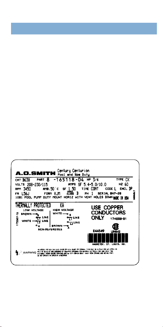
printed on the motor nameplate. On A.O. Smith
motors the nameplate is usually found on the side of the
m o t o r, below the capacitor. Shown below is a sample
pool motor identification nameplate. As you read the
nameplate, refer to the guide so that you understand
the meaning of each item that the manufacturer
p r ovides about its motor. Remember also that your
dealer or distributor can give you valuable inform a t i o n
that can help you to make the correct selection of a
replacement motor.
9
NAMEPLATE INFORMATION
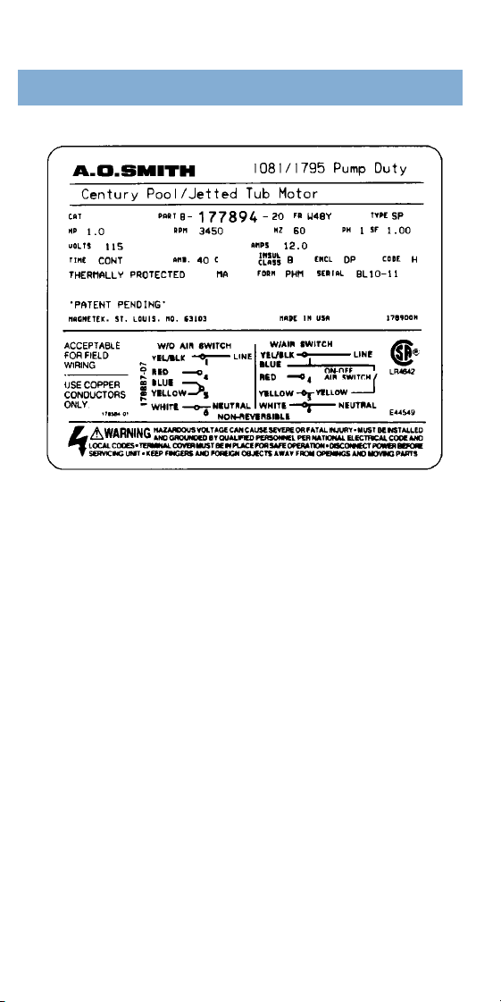
1 .C AT NO (Catalog Number): This number indicates
that the motor is a stock rating, readily available
f rom standard inventory as a replacement pool
m o t o r.
2 .PA R T: This identifies the motor’s specific design
by part number.
3 .FR (Frame): The frame identifies the mounting
and shaft configuration. It doesn’t indicate the
diameter of the shell. A.O. Smith’s line of Centurion
and Centurion SE motors have a “56 frame” shell
and are 6.5 inches in diameter. Neptune and
Flex-48 products are designed in a 48 frame shell
and are 5.6 inches in diameter. Common terms you’ll
see on the nameplate are “56J,” “56C” and “56Y.”
The 56J is always a C-flange, threaded-shaft motor;
the 56C is always a C-flange, keyed-shaft motor.
M o t o r-frame mountings with the “Y” identification
1 0

identify motors not specified by NEMA mounting
and shaft standards.
4 .T Y P E : The electrical design of the motor is shown
by its type. A.O. Smith uses “CX” to identify its
switchless design. Other codes include “CS” for
c a p a c i t o r- s t a r t, “S P” for split-phase and “CP” for
capacitor start / capacitor run. Be sure to check with
the dealer or distributor, because motor type codes
may vary among manufacture r s .
5 .HP (Horsepower): Conventional unit of measure -
ment for power. One horsepower equals 746 watts.
6 .RPM (Revolutions Per Minute): RPM states the
rotational speed of the shaft at rated load.
7 .HZ (Hertz): M e a s u r ement of fre q u e n c y, equaling
cycles per second of alternating curre n t .
8 .PH (Phase): Denotes a single- or three-phase
m o t o r.
9 .SF (Service Factor): S e rvice factor is the measure
of the re s e r ve margin built into a motor. Motors
rated over 1.0 SF allow the motor to operate at a
higher margin than designated by the horsepower
rating. Maximum horsepower capability equals
horsepower multiplied by the SF.
(continuous operation).
1 0 .V O LT S : Voltage is the re q u i r ed electrical potential
applied to the motor, the force that produces current
in an electrical conductor.
1 1 .A M P S : Electrical current flowing through the
conductors. On pool motors, the amperage is
maximum or service factor amps that result at
1 1
NAMEPLATE INFORMATION

maximum horsepower (Hp x SF).
1 2 .T I M E : Time indicates the duty cycle of the motor.
Pool and spa motors are generally rated for
continuous duty.
1 3 .AMB (Ambient Te m p e r a t u re ) : The maximum
ambient (surrounding) temperature in which the
motor is designed to operate. This temperature
is shown in Celsius rather than Fahre n h e i t .
1 4 .INSUL CLASS (Insulation Classification):
The temperature rating of insulation used in the
c o n s t r uction of the motor. Most pool and spa
motors use a Class “B” insulation.
1 5 .ENCL (Enclosure ) : Common enclosures used
include DP (dripproof) and TEFC (totally enclosed
fan cooled). Most pool and spa motors feature a
d r i p p roof design, with “1081” features.
1 6 .CODE: The NEMA code letter specifies locked
rotor kVA per Hp (volts multiplied by locked rotor
amps, divided by 1000 times rated HP).
1 7 .S E R I A L : The serial indicates the date of
m a n u f a c t u r e, which often appears as year/month
combinations. Serial code information for each
pool and spa motor can be found in guides and
bulletins provided by the manufacturer (See p.55).
1 8 .V O LTAGE DIAGRAM: This diagram provides
i n f o r mation on the correct electrical connections
to ensure proper operation of the motor.
1 9 .WA R N I N G : The warning at the bottom of the label
re-emphasizes that voltage can be hazardous.
Always TURN THE POWER OFF before working on
a pool or spa motor.
1 2

The number one enemy of a motor is
heat. Overheating always re s u l t s
whenever there is a lack of clean, continually-circ u l a t i n g
air for a motor. Heat can damage a motor’s windings,
insulation, bearing lubricant and run capacitor. In short ,
heat can quickly decrease the service life of a motor.
R e m e m b e r, proper ventilation is always a crucial consid-
eration when installing a motor.
If at all possible, install a motor in a location that is
f r ee of dirt, dust or airborne debris, such as leaves.
Indoors is best, but not in areas with high humidity,
such as a laundry room or shower area. If the motor is
installed outdoors, try to choose a shady spot that’s pro-
tected from leaves and grass clippings. If you cover the
motor to protect it from possible debris or water, be
s u re to leave enough space between the cover and the
motor for adequate ventilation.
A.O. Smith single phase pool and spa motors
f e a t u r e a thermal overload protector that will shut down
the motor if it overheats. As the windings begin to cool
down, the overload protector will automatically re - s t a r t
the motor. Blocked ventilation or an overload condition
can cause the motor to shutdown on a repeated basis.
If a problem cannot be located or if tripping continues
after a noted problem is corrected, contact the original
equipment contractor for a recommendation on
matching motor horsepower to the pump.
T I P : In situations where the ambient temperature is
exceptionally hot, utilizing an E-Plus (High Efficiency)
motor in place of a standard efficient motor can
p r event the overload protector from nuisance tripping.
1 3
H E AT
INSTALLATION

C e n t u ry and Neptune
motors have superior
resistance to moisture, but you should avoid placing
the motor where it can be splashed. Avoid installing the
motor in low spots where it could collect water and be
flooded. In fact, it’s probably a good idea to elevate the
motor at least two inches off the gro u n d .
B e f o r e you turn
the motor on,
check to see that the line voltage, phase and fre q u e n c y
match the specifications shown on the motor name-
plate. Current capacity must be adequate enough to
maintain rated voltage at the motor terminals under
all conditions. If it’s too high, contact the local utility.
If it’s too low check for overloaded circuits, loose
connections or wire of the wrong gauge (see wire
selection guide).
G e n e r a l l y, motors will
run hotter with increasing
altitudes. For installations more than 3,300 feet above sea
level, it’s advisable to use a motor with the next
l a r ger horsepower rating than the one recommended
for that application at sea level or use a A.O. Smith E-Plus
(High Efficiency) motor of the same rating when available.
Fastening the pump and
motor assembly securely
to a foundation or base will prevent vibration, loosening,
and future misalignment. Make sure that the motor and
pump assembly rotate freely before starting the motor.
1 4
M O I S T U R E
P OWER SOURCE
A LT I T U D E
M O U N T I N G

The task of wiring
your motor is fairly
simple. The wiring
diagrams shown on the following pages are color- c o d e d
for easy reading. The appropriate part number is listed
in each illustration, just in case you need to order the
complete wiring diagram or connection label sticker
for your motor. Make sure the connections are tight
to prevent failure or overheating. If you do find loose
connections, check for excessive vibration.
Without proper gro u n d i n g
of a motor, serious elec-
tric shock is possible. A grounding conductor should
always be connected under the green grounding scre w,
which is located within the terminal compartment of the
m o t o r. National and local electrical codes are import a n t ,
and should be adhered to when working
on a motor.
I n c o r rect voltage at the
motor terminals can cause
the motor to overheat. It’s a good idea to check the
electrical supply wires to confirm that they are suff i c i e n t
to handle the motor load. For example, if you’re using
a 1-
1
⁄
2
Hp motor at 115 volts over a distance of 150 feet,
use #8 wire. If the motor can be installed to
operate on 230 volts, #12 wire should be sufficient
for a 150 foot distance.
1 5
G R O U N D I N G
WIRE SIZE
E L E C T R I C AL
C O N N E C T I O N S
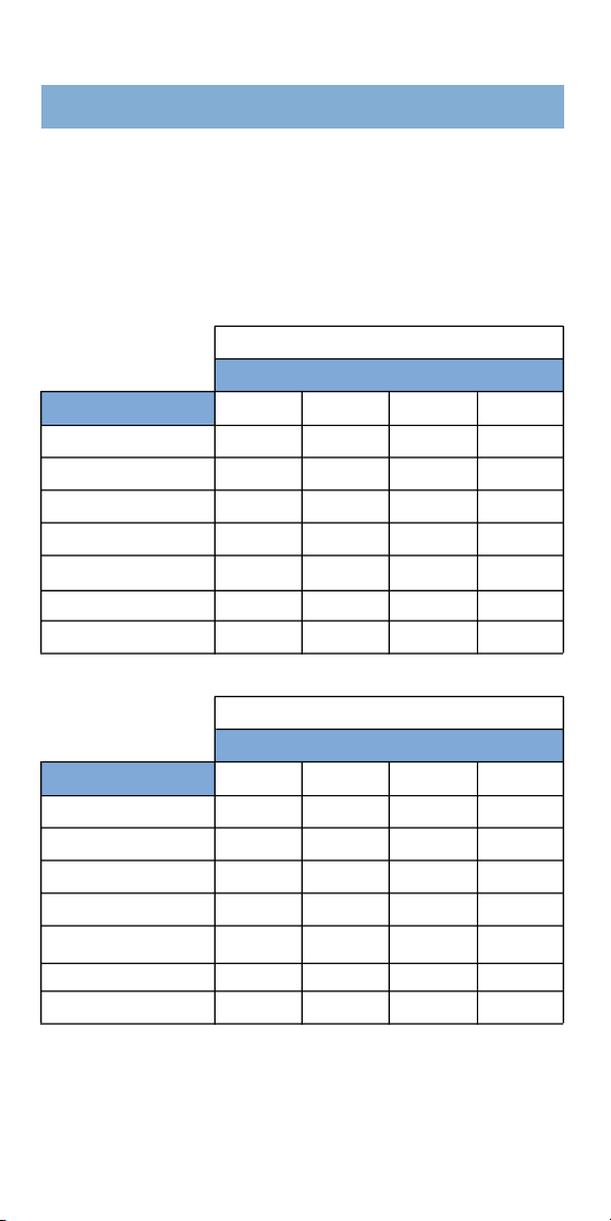
1 6
115V Power Line
Maximum Distance from Fuse Box to Motor
Motor Hp 5 0 ’ 1 0 0 ’ 1 5 0 ’ 2 0 0 ’
1
⁄
3
1 4 1 4 1 2 1 2
1
⁄
2
1 4 1 2 1 0 1 0
3
⁄
4
1 2 1 2 1 0 8
1 1 2 1 0 8 8
1 -
1
⁄
2
1 0 1 0 8 6
2 1 0 8 6 6
3 — — — —
230V Power Line
Maximum Distance from Fuse Box to Motor
Motor Hp 5 0 ’ 1 0 0 ’ 1 5 0 ’ 2 0 0 ’
1
⁄
3
1 4 1 4 1 4 1 4
1
⁄
2
1 4 1 4 1 4 1 4
3
⁄
4
1 4 1 4 1 4 1 4
1 1 4 1 4 1 4 1 2
1 -
1
⁄
2
1 4 1 4 1 2 1 2
2 1 4 1 4 1 2 1 0
3 1 2 1 2 1 0 1 0
THE SIZES SHOWN IN THE FOLLOWING WIRE SELECTION
C H A RTS ARE RECOMMENDATIONS ONLY. ALWAYS FOLLOW
LOCAL AND NATIONAL ELECTRIC CODES.
Guides for copper conductors only.
WIRE SELECTION GUIDE

1 7
W
ith a few simple tools, you’ll be ready for just
about any kind of basic motor service. To make
your job easier when installing or servicing a
pool or spa motor, make sure that you have these tools
in your toolbox before you begin working...
• S t a n d a rd scre w d r i v e r
• Wide blade scre w d r i v e r
•
1
⁄
2
” open end wre n c h
• Rubber mallet
• Clamp-on ammeter/voltmeter
• A m m e t e r
•
5
⁄
1 6
” nut driver
• Needle-nose pliers
• Tape for marking
A
.O. Smith pool and spa pump motors are built
tough, to run day after day without being serv i c e d .
When service is necessary, serviceable parts usu-
ally can be accessed quite easily. For example, capaci-
tors are externally mounted, and single-phase motors
have screw-type connectors for quick reconnection in
the field.
Water leaks from pump
seals or pipe joints should
be re p a i red to prevent failure of bearings and insulation.
DO NOT splash or spray the motor. Mount the motor
away from low spots and damp areas, and take mea-
s u res to protect it from windblown rain.
M O I S T U R E
MAINTENANCE
TOOLS

1 8
An operating motor is usually
too hot to touch by hand.
It should be located away from direct sunlight and other
heat sources, such as laundry appliances and water
heaters. Provide for ample air circulation around the
m o t o r. Clean the air inlets as re q u i red, making sure that
the POWER IS OFF first.
Whenever the motor must
be shut down for extended
periods, be sure all surfaces, vents and interiors are dry
to prevent rust. If the motor is kept outdoors, cover it
to prevent debris such as blowing leaves, dirt and snow
f r om clogging the inlets. DO NOT SEAL THE MOTOR
IN PLASTIC OR OTHER AIR-TIGHT WRAPPINGS,
because condensation may form on the inside,
damaging bearings and insulation.
In general, the inside of
the motor should not need
cleaning if proper safeguards are made against contami-
nation by dirt, lint or sand. If you want to clean the
outside, simply use a damp cloth. Don’t spray the motor
with a water hose. If it’s accidentally flooded, have it
inspected at a A.O. Smith authorized service center.
The ball bearings
in A.O. Smith
motors are double sealed, permanently lubricated. If it
appears the bearings have failed, simply replace them.
C O O L I N G
S E A S O N A L
C L E A N I N G
L U B R I C AT I O N
MAINTENANCE

1 9
B e f o r e you even touch the
m o t o r, MAKE SURE THE
POWER IS OFF. Always turn the power off at the
electrical service entrance fuse or breaker box, to
p revent possible electric shock. To prevent electrical
shock when touching the motor, be sure windings and
capacitor are securely grounded to the ground term i n a l
which should be used in conformity with local codes.
D o n ’ t work on electrical operations if water or moist
conditions cannot be avoided. If the motor is not
operating pro p e r l y, refer to the following guide.
MOTOR FAILS TO STA RT (makes no sound)
1 .Check the obvious first — are the power switch
and timer on?
2 .Be sure fuses are of proper size and type, then
check for a blown fuse or tripped circuit bre a k e r.
3 .Be sure the motor is connected correctly (as shown
on motor nameplate), but first — TURN OFF THE
POWER. Check the terminal screw to see if it was
tightened onto wire insulation instead of the wire
itself. Verify that the ground wire is firmly
connected to the green ground scre w.
4 .Check the voltage at terminal board after first
TURNING THE POWER BACK ON. Be sure you turn
the POWER BACK OFF after completing this step.
NOTE: Voltage at motor terminals should be ±10%
of voltage on nameplate. If the voltage is high
( m o re than ±10% above nameplate number),
consult the local power company. If the voltage is
low (±10% below rated voltage), check the size of
the power line from fuse box to motor. If the
WA R N I N G
MOTOR TROUBLESHOOTING

2 0
voltage is within the proper range, check for
continuity through the pro t e c t o r.
5 .Check for overloading from other appliances on
the same circuit as the motor.
6 .Inspect the motor windings for continuity.
7 .If voltage is proper at terminals and the motor is
cold, remove the motor and take it to a A.O. Smith
Authorized Service Center.
MOTOR FAILS TO STA R T (hums, tries to start, blows
fuse or trips bre a k e r )
1 .Check the motor connections after TURNING OFF
THE POWER.
2 .Check the voltage (see #5 above) as the motor tries
to start. If voltage is too low, look for undersized
wiring, an overloaded circuit or a burned start
w i n d i n g .
3 .If the voltage is proper at terminals and motor is
hot, TURN OFF THE POWER and allow the motor to
cool to ambient temperature then reapply power.
If the motor starts then shuts down, you have an
overload. Check the amp draw at the motor
t e rminal and compare it to amps shown on the
motor nameplate. If the amp draw is greater then
the nameplate current, check for impeller rub in the
pump or a tight seal. If this fails to correct the
p r oblem, remove the motor from pump and take to
a A.O. Smith Authorized Service Center.
4 .Check the capacitor but first — TURN OFF THE
POWER. After removing the capacitor from the
m o t o r, discharge it by laying an insulated
s c r ewdriver across its terminals. Check the

2 1
capacitor using an ohmmeter (see
“ Troubleshooting A Capacitor” page 23).
5 .Rotate the motor shaft. If you hear a grinding
sound, disassemble the motor and check: the
conditions of bearings, a rotor rubbing the stator,
c o rrosion, a cracked frame, clogged fan or
o b s t ruction(s). Repair or replace any faulty part ( s ) .
6 .If the motor has a switch, disassemble the motor
and check the contacts for dirt. Use brown Kraft
paper to gently clean. If the motor still doesn’t
work, replace the switch.
7 .If the switch contacts are open, check the governor
for free movement on the shaft. (Incidentally, with
a Centurion motor you won’t have this problem,
because it doesn’t have a switch to malfunction.)
MOTOR STA RTS BUT SHUTS DOWN (Therm a l
Overload Pro t e c t i o n )
1 .Check the voltage at motor terminal (see #5 under
“Motor Fails To Start”). If the voltage is too high,
call power company.
2 .Check amperage. If high, find out it the pump
impeller was recently replaced (it could be sized
i n c o rrectly). Remember, motor Hp x SF = the
maximum Hp capability of motor. This number
must be equal to or greater than the pump rating.
NOISY MOTOR
Air noise is normal, but an excessively high sound
level or rough operation can mean trouble. If necessary,
separate the motor and pump to find out where the fault
lies. If it’s in the motor, check the following items:
MOTOR TROUBLESHOOTING

2 2
1 .Mounting, motor coupling and brackets. Tighten
loose nuts, bolts or set scre w s .
2 .If a noticeable drag is present, check the bearings
and bearing load spring.
3 .Make sure motor fan moves freely and rotor isn’t
rubbing stator. Look for loose or binding parts
inside the motor or pump.
4 .Check for malfunctioning motor start switch and
g o v e rn o r.
If the problem appears to be with the pump, look for a
loose motor coupling, loose or damaged pump impeller,
clogged pump filter or strainer, or cavitation (loss of
prime or air leaks on the pump’s suction side).
MOTOR HOT, SMOKING OR CYCLING
1 .Check the motor’s ventilation by looking for
clogged air vents or openings. Clean out all leaves,
d i rt and other pool and spa gunk.
2 .C o m p a re connections and wiring to diagrams.
Test the motor voltage to verify that it’s within
±10% of nameplate listing.
3 .If the voltage checks out but amps are higher than
the maximum on the nameplate, inspect motor and
pump for mechanical obstructions, but not before
TURNING OFF THE POWER.
4 .E n s u r e that the motor’s horsepower (Hp), times the
s e r vice factor (SF), is equal to or greater than the
pump rating (Hp x SF ≤ to Pump Rating). A
full-load current greater than the nameplate listing
can mean excessive pump load.
5 .Look at motor windings for damage or signs of
s h o rting. Measure winding re s i s t a n c e .
6 .Check the start switch for broken contact welds or
a broken spring.
7 .Check the capacitor with an ohmmeter. A bulged
capacitor indicates failure on most motors. But
with a Centurion, the only way to verify a failed
capacitor is with the ohmmeter.
I N F O R M ATION NEEDED FOR MOTOR REPLACEMENT
To get the right replacement motor, you’ll need impor-
tant information. Fort u n a t e l y, they all can be found on
the motor nameplate. Here ’s what you’ll need to know:
1 .Mounting configuration - C-Bracket, Square Flange,
or Through-bolt Mount (See page 5-7).
2 .H o r s e p o w e r
3 .S e rvice factor
4 .Vo l t a g e
5 .Pump part number, manufacturer brand name
TROUBLESHOOTING A CAPA C I T O R
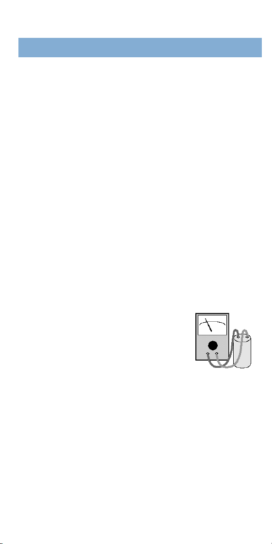
To check a capacitor with an ohmmeter,
first TURN OFF THE POWER. If possible,
remove the capacitor from the motor.
Use an insulated screwdriver to discharg e
the capacitor by shorting it across its terminals.
Then set the ohmmeter to its highest setting and attach
the ohmmeter’s clips to the capacitor’s terminals.
Check for the following indications:
1 .Needle drops to zero range and slowly rises —
capacitor is probably OK.
2 .Needle drops to zero and stays there —
capacitor most likely is short e d .
3 .Needle remains at a high value — capacitor may
have an open circ u i t .
2 3
MOTOR TROUBLESHOOTING
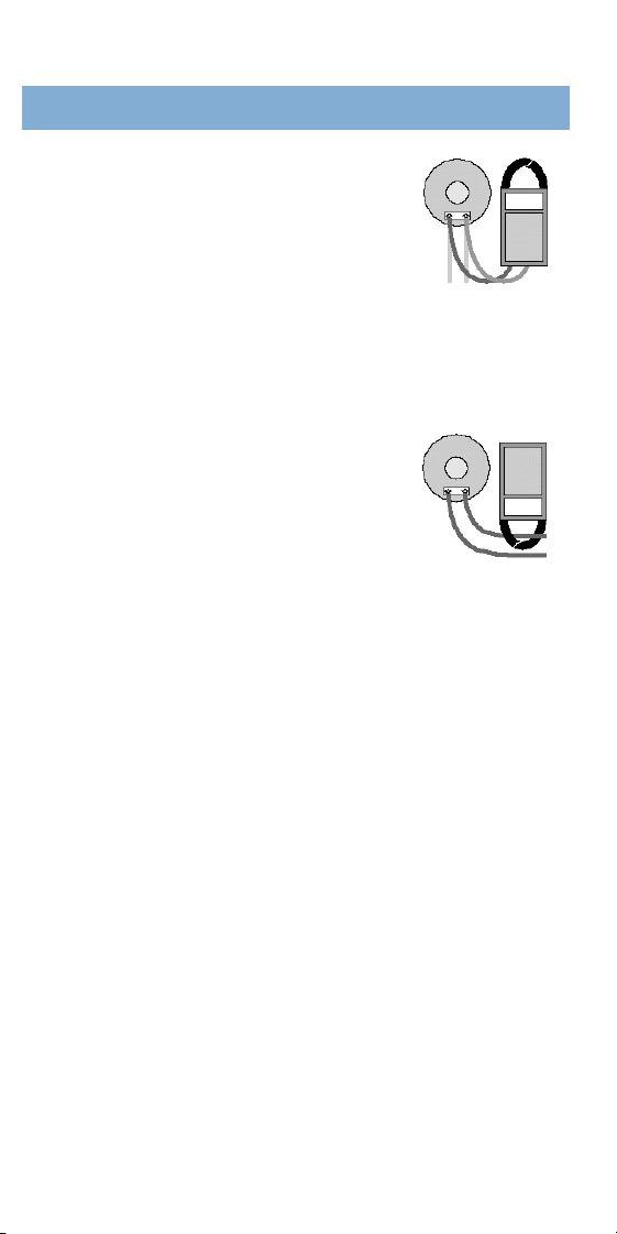
BEST WAY TO USE A VOLT-AMMETER
For Voltage Check
1 .Attach leads to the volt-ammeter
and select the proper voltage scale.
2 .Test voltage at the motor line terminals and verify
that it’s within limits while the motor is operating.
3 .Voltage should be within ±10% of the design
voltage specified on the motor nameplate.
For Amperage Check
1 .Remove the leads from the
volt-ammeter if attached. Select
lowest reading amperage scale
a c c o rding to motor nameplate rating.
2 .Clamp instrument around one incoming lead at the
motor terminal board .
3 . O b s e rve the amperage as motor runs. With proper
voltage, the reading should not exceed the
MAXIMUM LOAD or SF amps rating of the motor.
HOW TO REPLACE BEARINGS
Replacing the bearings in a motor isn’t a difficult task,
p r ovided you follow set pro c e d u res. These instru c t i o n s
explain the correct method of motor bearing re m o v a l
and replacement. If a bearing is noisy or doesn’t ru n
s m o o t h l y, it should be replaced. If a bearing has been
removed for any reason, it should be replaced with a
new one. As a rule, if it’s necessary to replace one
bearing, replace the other as well.
Use only A.O. Smith bearings with the proper part
number for the motor that you’re working on. A.O.
Smith bearings are lubricated and re q u i re no furt h e r
attention during their life. Do not substitute or reuse old
2 4
bearings because this could damage the motor and
cause a re t u rn service call.
1.TURN THE POWER OFF
2 .Remove the cover from the motor and disconnect
the electrical supply leads from the terminal board.
Then remove the electrical cable
or conduit from the end frame.
3 .Remove the motor from the
pump unit.
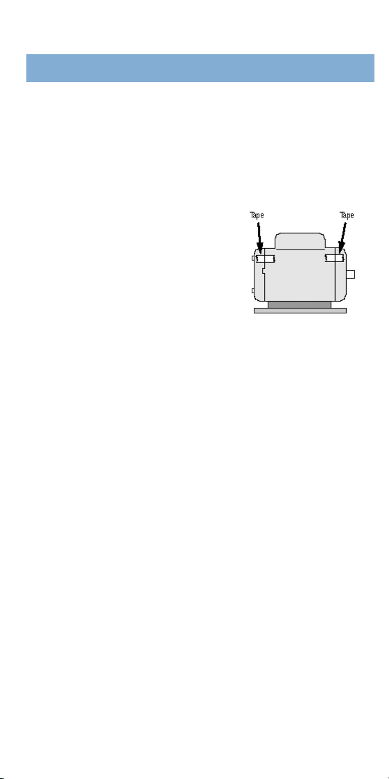
4 .Mark the brackets and frame
of the motor, to assure corre c t
alignment of these parts when reassembling them.
5 .Remove the rotor and shaft from the frame of the
m o t o r, following these steps as necessary :
a )Take out the thru-bolts that secure the brackets
to the frame.
b )Remove the bracket opposite the shaft by
placing a screwdriver blade in the notches of
this bracket and tapping the handle of the
s c re w d r i v e r.
c )Remove the locking collar screws and washers if
their use prevents removal of the rotor assembly
f r om the shaft end bracket.
d )C a r efully pull the shaft/rotor assembly out of the
shell or stator toward the shaft extension end.
e )Be careful not to lose the washer and bearing
load spring that is positioned in the bottom of the
bearing bore of the bracket opposite the shaft
extension. Be sure to replace this spring during
re a s s e m b l y.
2 5
MOTOR TROUBLESHOOTING

6 .Remove the bearing(s) from the motor shaft,
following these steps as necessary :
a )Remove shaft collars used to secure bearings.
D o n ’ t reuse a bearing that is removed from
the shaft.
7 .Install the new shaft bearing(s). It is important
to press only on the bearing inner race. The
bearing will be damaged if the outer race surface
is pressed.
a )Fan end. Place the short end of the shaft on a
wood block. Place the bearing (and other parts
used) over the long end of the shaft. Tap the
bearing into place, using the proper size tube and
a mallet. Attach any other parts (as used) to the
long shaft end.
b )Opposite end. Place the long end of the shaft on
the wood block. Place the bearing over the short
end of the shaft. Tap the bearing into place, using
the proper size tube and a mallet.
8 .Reassemble the motor in reverse of the
disassembly pro c e d u re .
a )O b s e rve all reassembly pre c a u t i o n s .
b )Check wiring diagrams to assure proper wiring if
the leads have been removed from the term i n a l s .
c )TURN ON THE POWER. Check the motor for
p roper electrical and mechanical operation when
it has been re i n s t a l l e d .
2 6

I
f your pool or spa motor should need attention
while still under warr a n t y, we re q u i re that you have
it serviced at a Authorized A.O. Smith Service Center
to qualify for warranty coverage. When ordering part s ,
refer to the part number and serial number on
the motor nameplate.
For your convenience, a separate Century Stock
Pool and Spa Motor Parts List is available. Ask for
Bulletin #3996.
2 7
SERVICE

2 8
C e n t u r i o n
®
Switchless (Easy Connect) . . . . . . . . . . . . . . . . . . 29, 30
C e n t u r i o n
®
Switchless (Mfg. prior 11/91). . . . . . . 31, 32, 45
10 81, Wishbone (Old Style). . . . . . . . . . . . . . . . . . . . . . . . . . . . . 33, 34, 35
10 81, Single Arm Switch (Old Style). . . . . . . . . . . . . . . . . . . . . 36, 37
E - P l us
®
, Switchless (Old Style),230 volt . . . . . . . . . . . . . . . . . . . . . 3 8
2-Speed, Wishbone (Old Style). . . . . . . . . . . . . . . . . . . . . . . 39, 40, 41
M i c r o-Switch (Formerly Gould-Guard ). . . . . . . . . . . . . . . . . . . . . . . . 4 2
Switchless (Formerly Gould-Guard ). . . . . . . . . . . . . . . . . . . . . . 43, 44
C e n t u r i o n
®
Solid State. . . . . . . . . . . . . . . . . . . . . . . . . . . . . . . . . . . . . . . . . . . . . 46, 47
E - P l u s
®
Switchless (Mfg. prior 11/91) . . . . . . . . . . . . . . . . . . . 48, 49
L a s ar
®
48 Frame (Two Speed) . . . . . . . . . . . . . . . . . . . . . . . . . 50, 51, 52
Flex 48 (Single Speed). . . . . . . . . . . . . . . . . . . . . . . . . . . . . . . . . . . . . . . . . . . 53, 54
N e p t u n e. . . . . . . . . . . . . . . . . . . . . . . . . . . . . . . . . . . . . . . . . . . . . . . . . . . . . . . . . . . . . . . . . . . . 55, 58
WIRING DIAGRAMS
TABLE OF CONTENTS
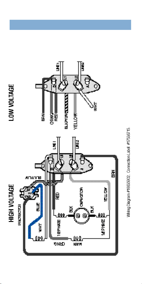
For motors manufactured in/after Nov., 1991 (Serial #BJ11)
Dual Vo l t a g e Type CX-
1
⁄
2
to 1
1
⁄
2
H p
230/115 Vo l t S w i t c h l e s s
2 9
CENTURION
®
/SE/II
3 0
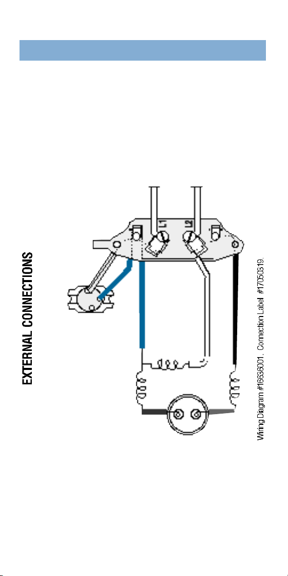
For motors manufactured in/after Nov., 1991 (Serial #BJ11)
Single Vo l t a g e Type CX-1
1
⁄
2
- 5 H p
230 Vo l t S w i t c h l e s s
CENTURION
®
/SE/II
3 1
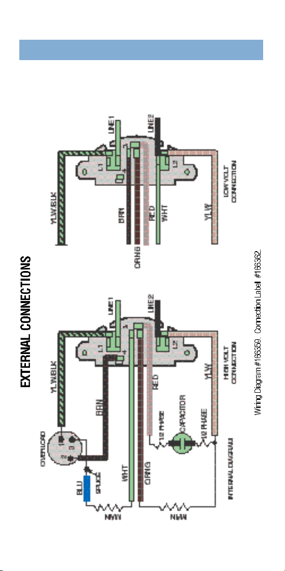
Dual Vo l t a g e
115/230 Vo l t
Type CX–
1
⁄
2
to 1
1
⁄
2
H p
Switchless
For motors manufactured prior to Nov. 1991. (Serial #BJ11)
CENTURION
®
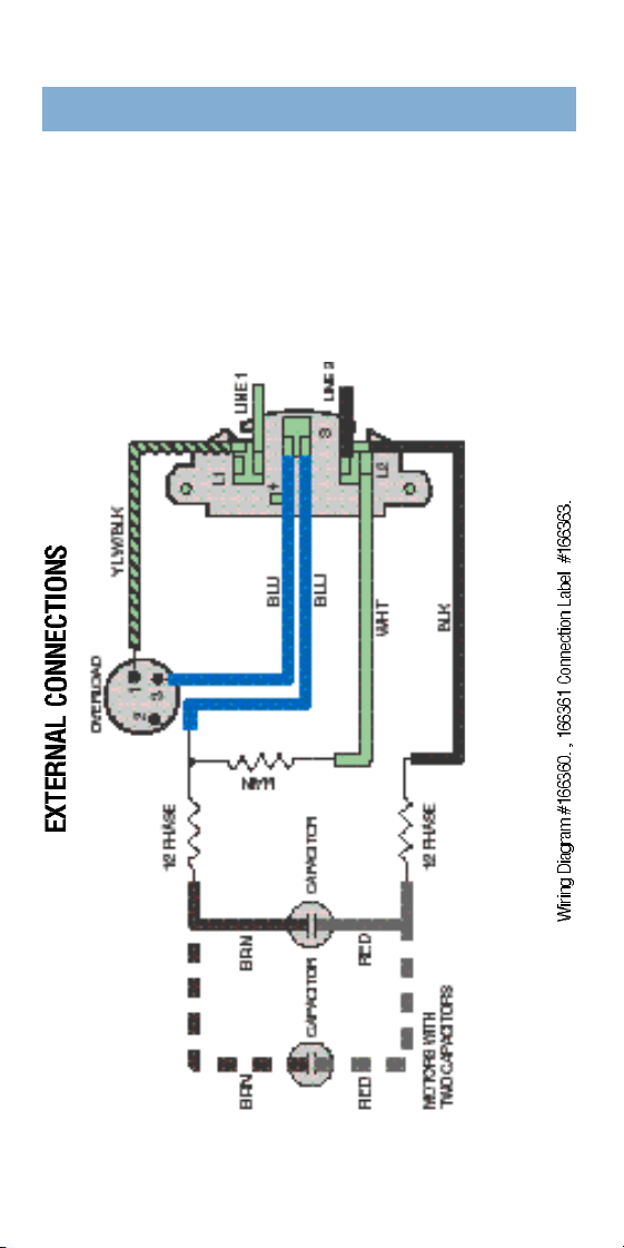
3 2
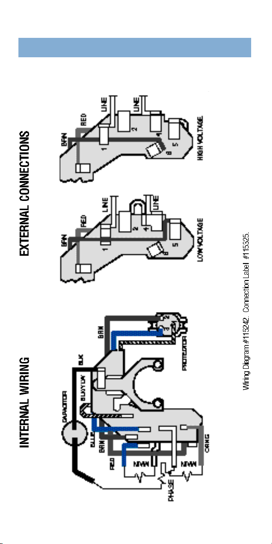
Single Vo l t a g e
230 Vo l t
Type CX–2, 3 & 4 Hp
Switchless
For motors manufactured prior to Nov. 1991. (Serial #BJ11)
CENTURION
®
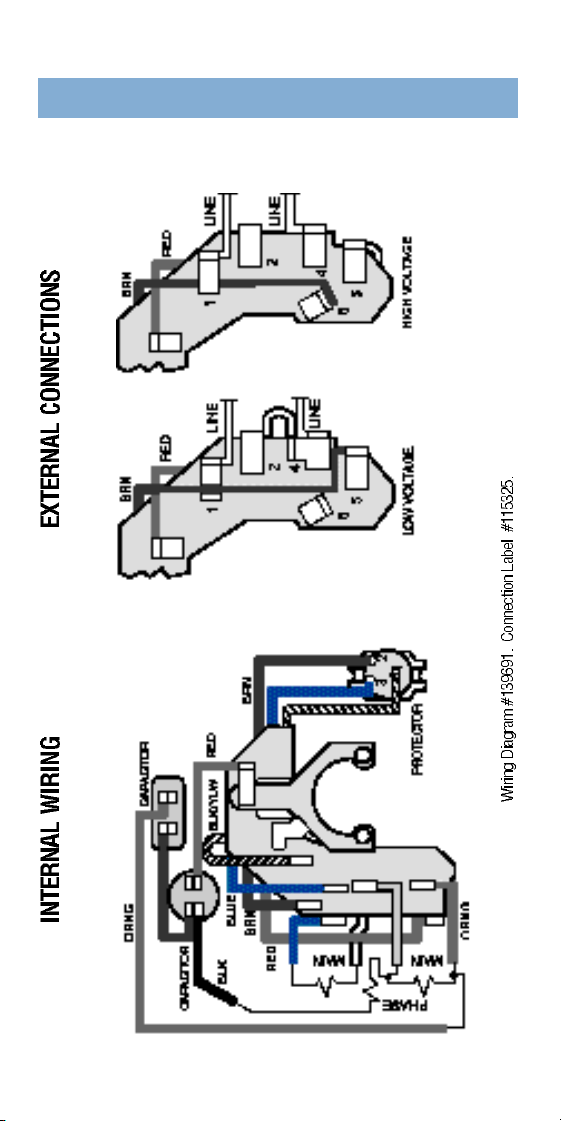
3 3
115/230 Vo l t Type CS–
1
⁄
2
to 1
1
⁄
2
H p
Wishbone (Old Style)
1081
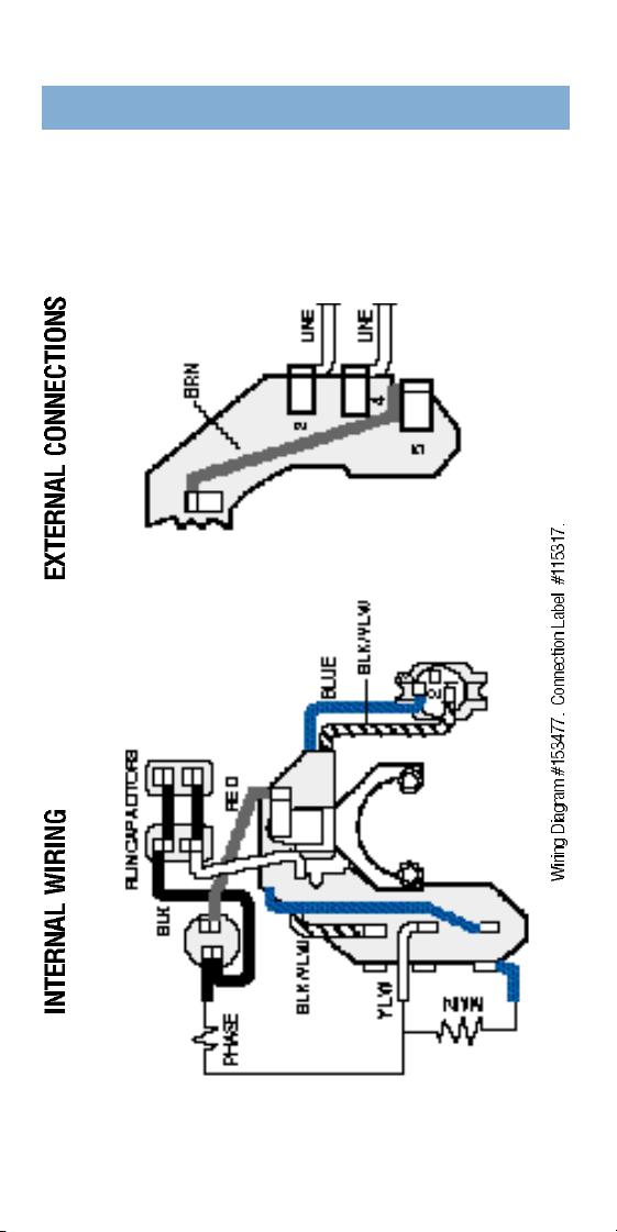
3 4
115/230 Vo l t Type CP–2 Hp
Wishbone (Old Style)
1081
3 5
230 Vo l t Type CP–3 Hp
Wishbone (Old Style)
1081
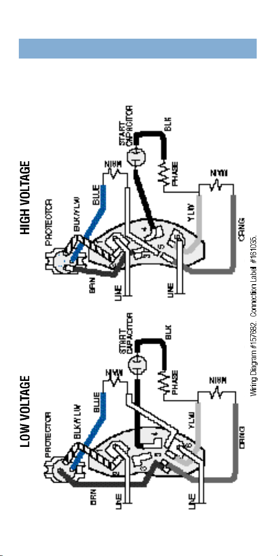
3 6
115/230 Vo l t Type CS–
1
⁄
2
to 1
1
⁄
2
H p
Single Arm Switch (Old Style)
1081
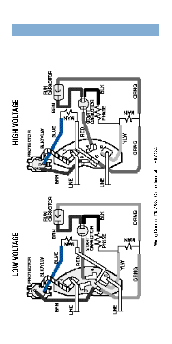
3 7
115/230 Vo l t Type CP–2 Hp
Single Arm Switch (Old Style)
1081
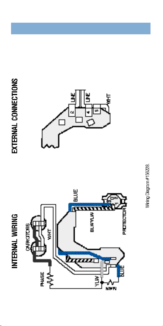
3 8
230 Vo l t Type CX–2 and 3 Hp
Switchless (Old Style)
E-PLUS
®
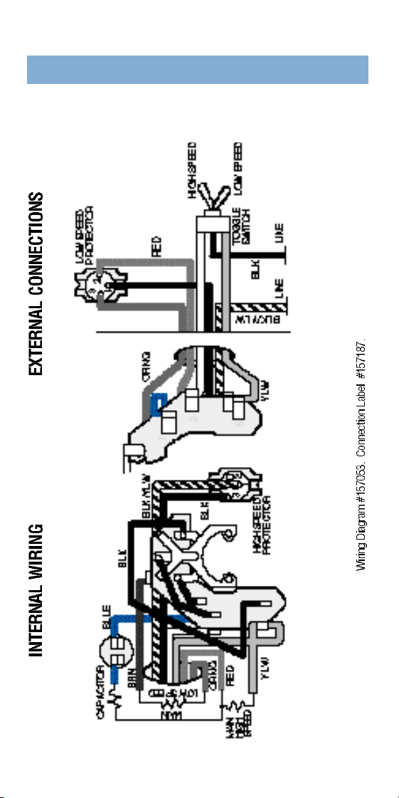
3 9
115 Vo l t Type CSM–
1
⁄
2
to
3
⁄
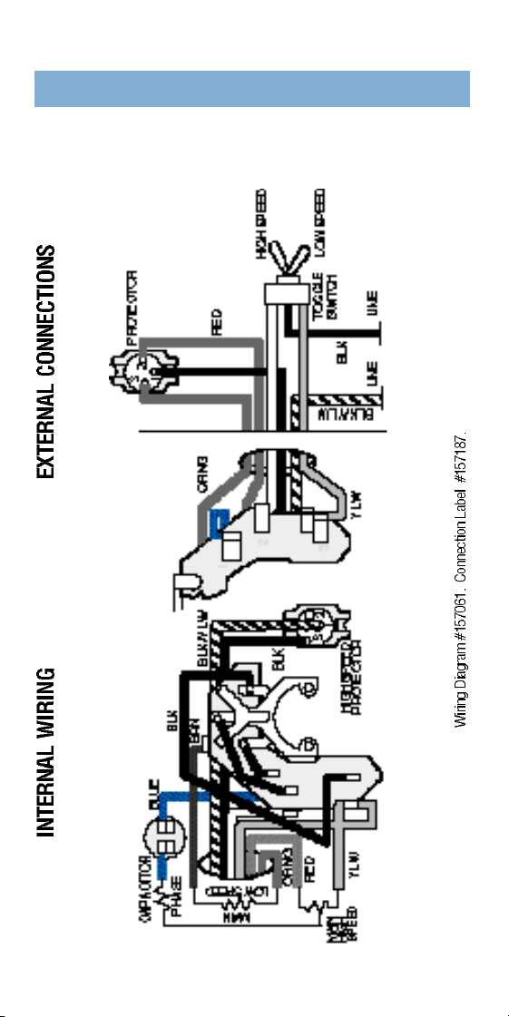
4
H p
Wishbone (Old Style)
2-SPEED
4 0
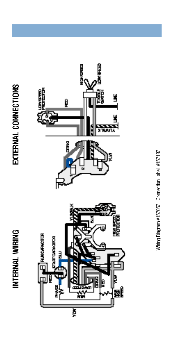
230 Vo l t Type CSM–1 and 1
1
⁄
2
H p
Wishbone (Old Style)
2-SPEED
4 1
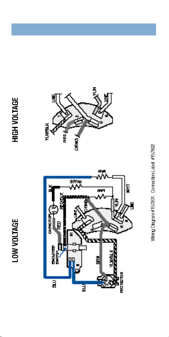
230 Vo l t Type CPM–2 Hp
Wishbone (Old Style)
2-SPEED
4 2
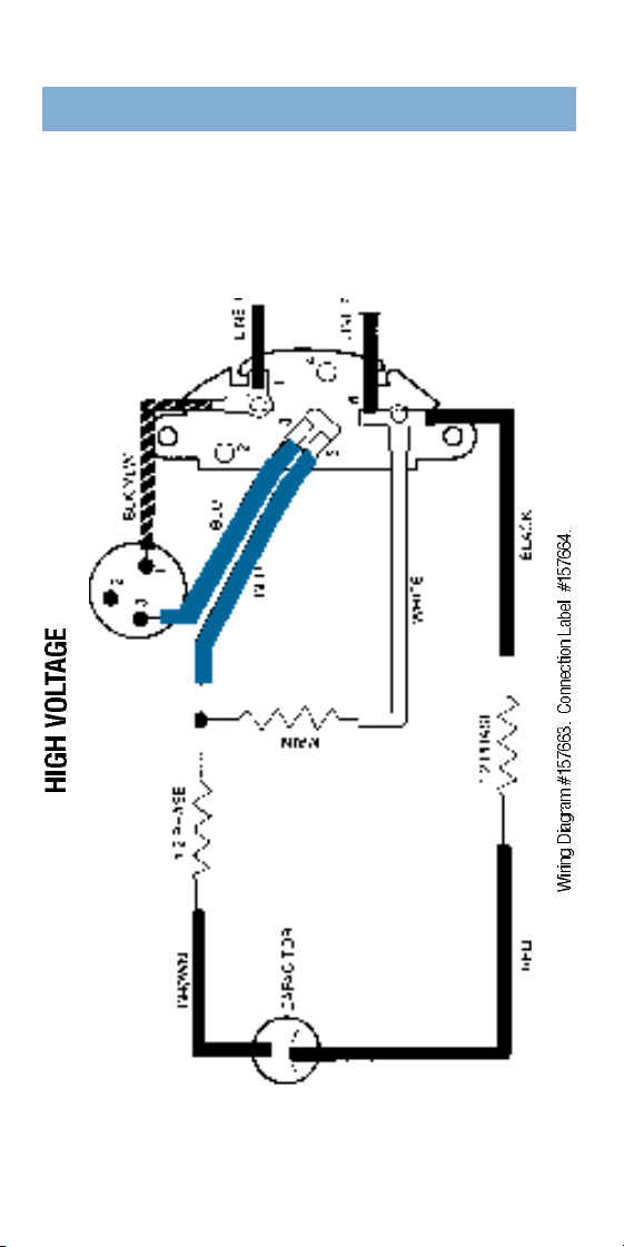
( F o rmerly identified as
G o u l d - G u a rd )
115/230 Vo l t
Type CS–
1
⁄
2
to 1 Hp
(Old Style)
MICRO-SWITCH MOTOR
4 3
( F o r merly identified as
G o u l d - G u a rd )
230 Vo l t
Type CX–1
1
⁄
2
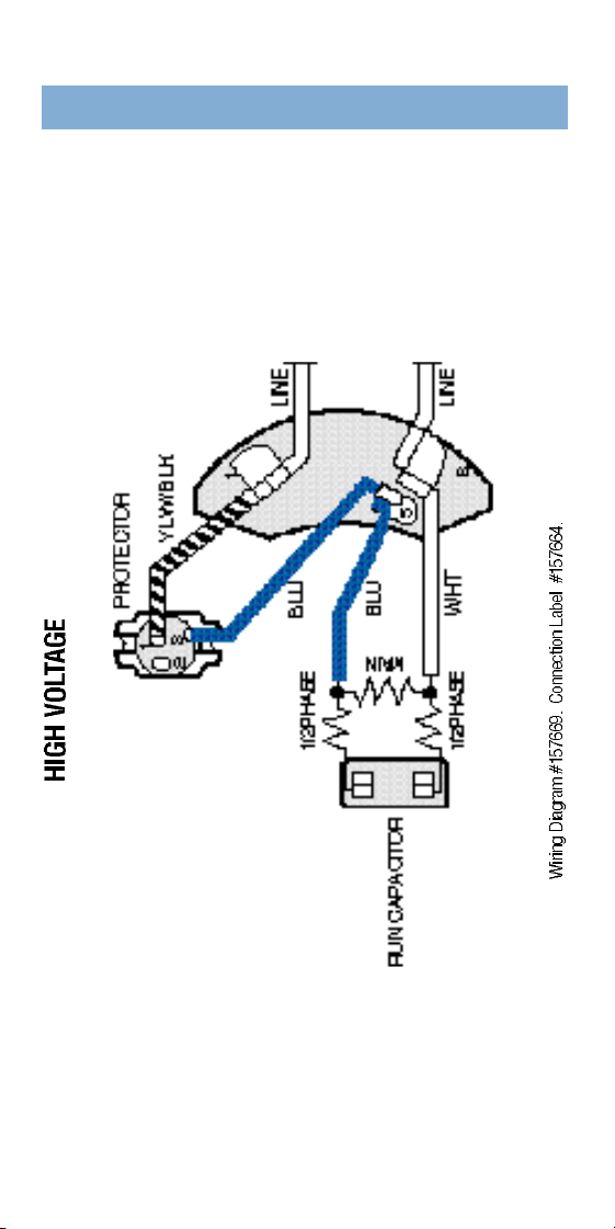
H P
Switchless (Old Style)
SWITCHLESS MOTOR
4 4
( F o r merly identified as
G o u l d - G u a rd )
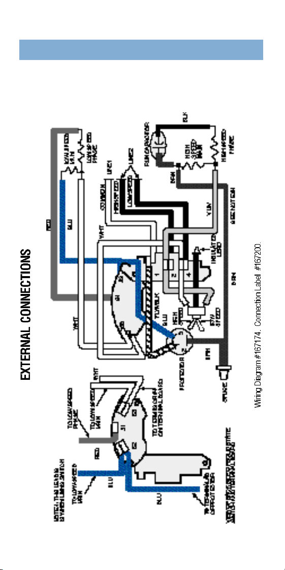
230 Vo l t
Type CX–2 and 3 HP
Switchless (Old Style)
SWITCHLESS MOTOR
4 6
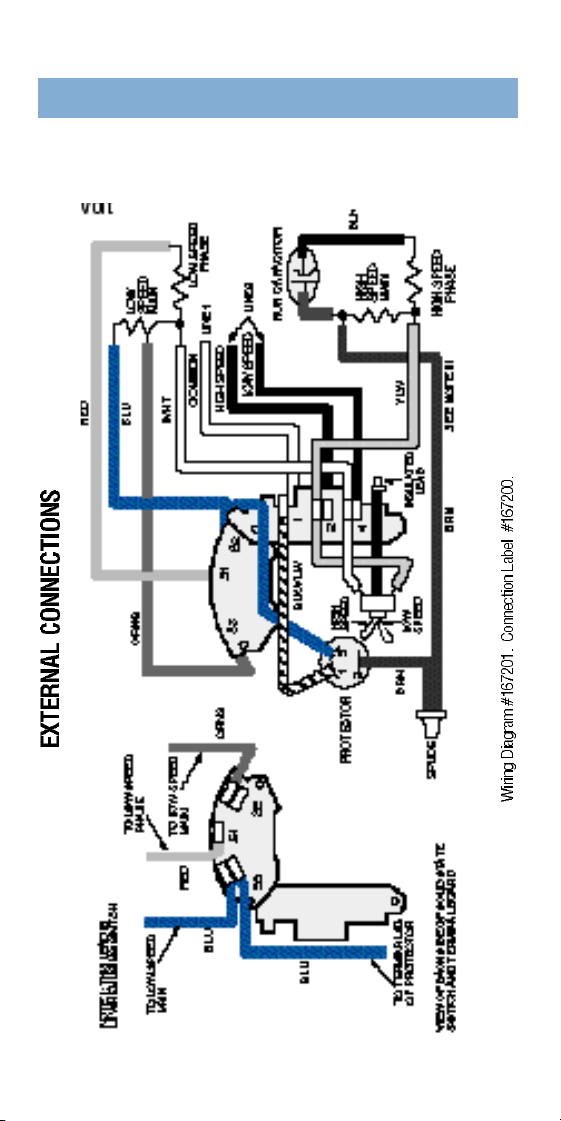
Two-Speed
Single Vo l t a g e
115 Vo l t
Type CXPM–
1
⁄
2
/.06 to
3
⁄
4
/.10 Hp
Solid-State Switch
CENTURION
®
4 7
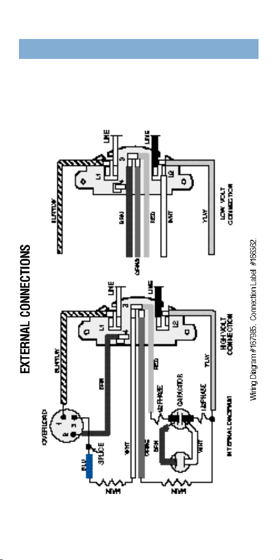
Two-Speed
Single Vo l t a g e
230 Vo l t
Type CXPM–1/.12 to 2/.25 Hp
Solid-State Switch
CENTURION
®
4 8
Dual Vo l t a g e
115/230 Vo l t
Type CX–
3
⁄
4
to 1
1
⁄
2
H p
Switchless
E-PLUS
®
SWITCHLESS
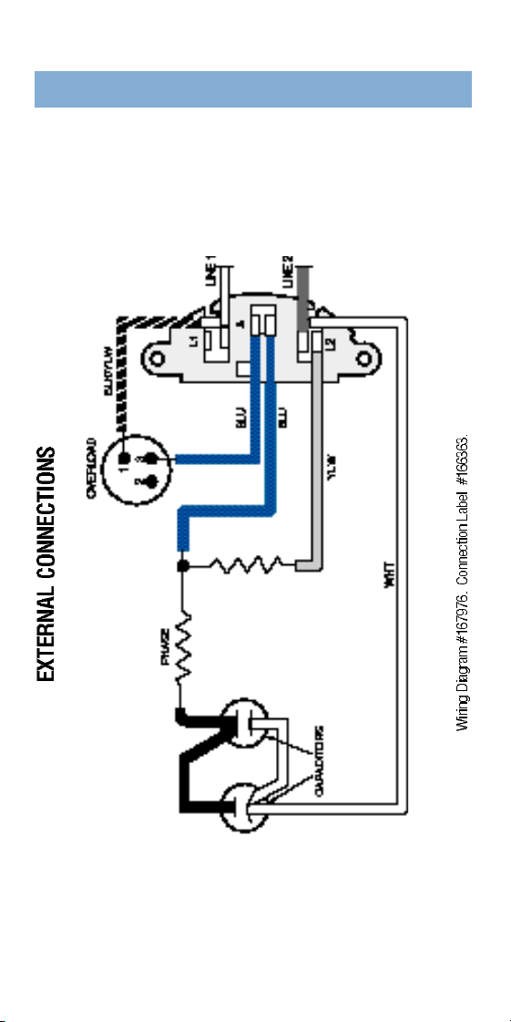
4 9
Single Vo l t a g e
230 Vo l t
Type CX–2 and 3 Hp
Switchless
E-PLUS
®
SWITCHLESS
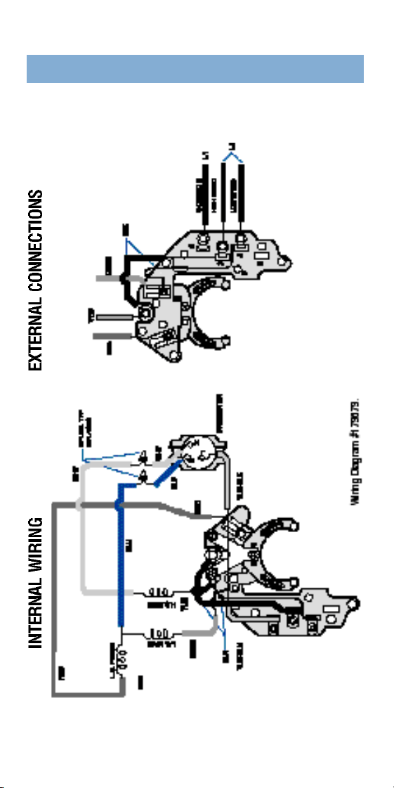
5 0
Two Speed Single Vo l t a g e
115 Vo l t
Type SPM–
3
⁄
4
/.10 HP
FLEX 48
®
FRAME
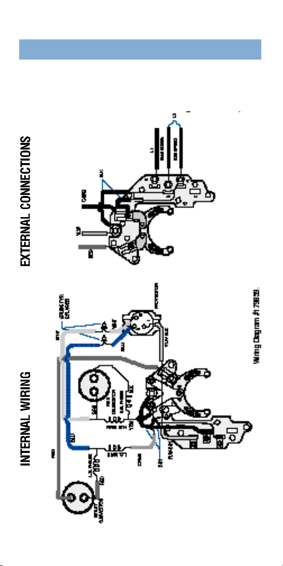
5 1
Two-Speed
Single Vo l t a g e
115 or 230 Vo l t
Type CXSM 1
1
⁄
2
/.18 HP
Type CXSM 2.0/.25 HP
t h rough 4.5/.50 Spl HP
FLEX 48
®
FRAME
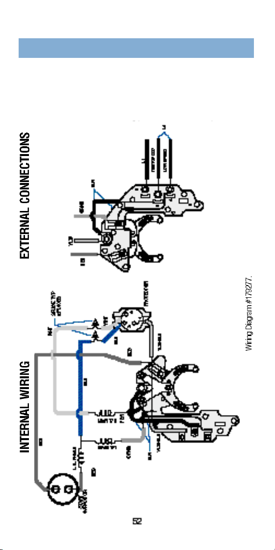
5 2
Two-Speed
Single Vo l t a g e
115 or 230 Vo l t
Type CSM 1.0/.12 Hp 115 Vo l t
Type CSM 1.0/.16 Hp 115 Vo l t
Type CSM 1.5/.18 Hp 230 Vo l t
Type CSM 2.0/.25 Hp 230 Vo l t
FLEX 48
®
FRAME
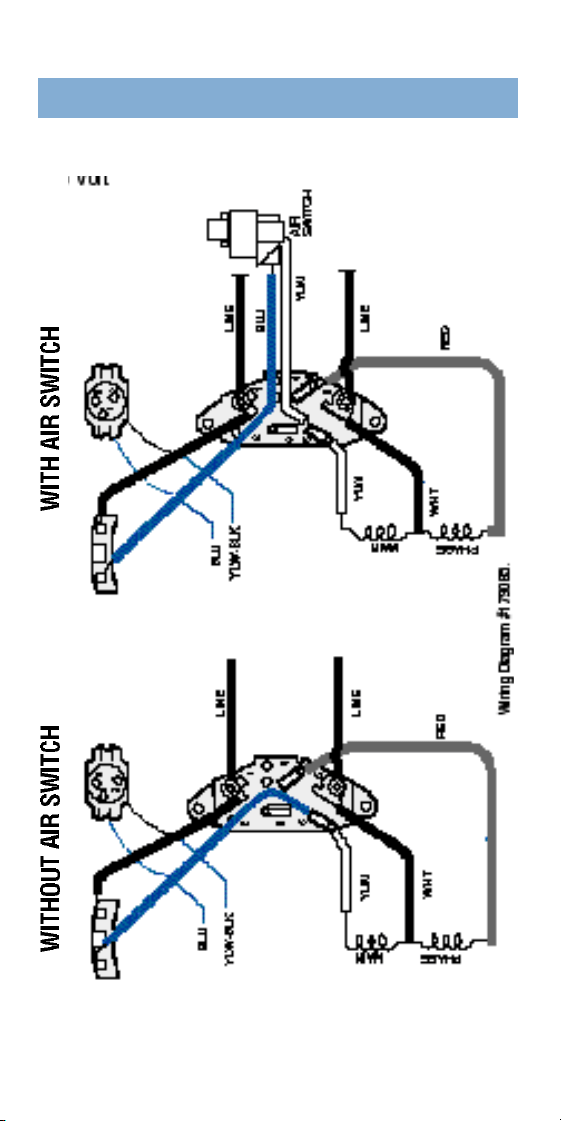
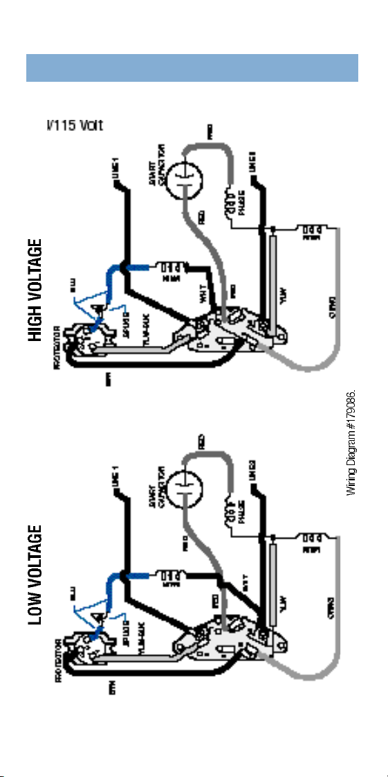
5 3
Single Vo l t a g e
115 Vo l t
Type SP–
1
⁄
2
to 1
1
⁄
2
H p
FLEX 48
®
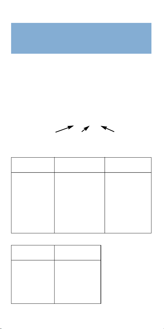
5 4
Dual Vo l t a g e
230/115 Vo l t
Type CS–1
1
⁄
2
to 4 Spl Hp
FLEX 48
®
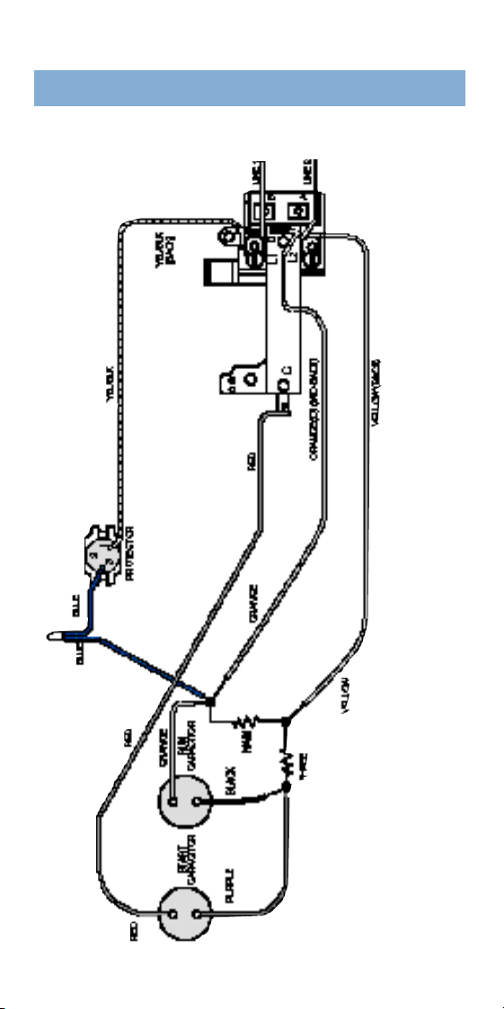
5 5
For Century Pool, Spa or Jetted Tub Motors
To identify the month and year your Century pool, spa
or jetted tub motor was manufactured you need to know
the serial code.
The serial code on the nameplate is made up of thre e
p a rts: serial letter (year), serial number (month), and
manufacturing sequence number. Example:
SERIAL BH 1 1 - 1 6
Serial Letter Serial Number Mfg. Sequence
This motor was manufactured in November 1990.
S e r i a l S e r i a l S e r i a l
L e t t e r Ye a r L e t t e r Ye a r L e t t e r Ye a r
K 1 9 7 0 W 1 9 7 9 B F 1 9 8 8
L 1 9 7 1 X 1 9 8 0 B G 1 9 8 9
M 1 9 7 2 Y 1 9 8 1 B H 1 9 9 0
N 1 9 7 3 Z 1 9 8 2 B J 1 9 9 1
P 1 9 7 4 B A 1 9 8 3 B K 1 9 9 2
R 1 9 7 5 B B 1 9 8 4 B L 1 9 9 3
S 1 9 7 6 B C 1 9 8 5 B M 1 9 9 4
T 1 9 7 7 B D 1 9 8 6 B N 1 9 9 5
U 1 9 7 8 B E 1 9 8 7 B P 1 9 9 6
Serial Letter Designation
S e r i a l S e r i a l
L e t t e r Ye a r L e t t e r Ye a r
1 J A N 7 J U LY
2 F E B 8 A U G
3 M A R 9 S E P T
4 A P R 1 0 O C T
5 M AY 1 1 N O V
6 J U N E 1 2 D E C
Serial No. Designation
HOW TO IDENTIFY
THE DATE OF
MANUFACTURE
5 6
Single Vo l t a g e 230 Vo l t
Type CP 1
1
⁄
2
2&3 Hp
N E P T U N E
®
2 Compartment Motors
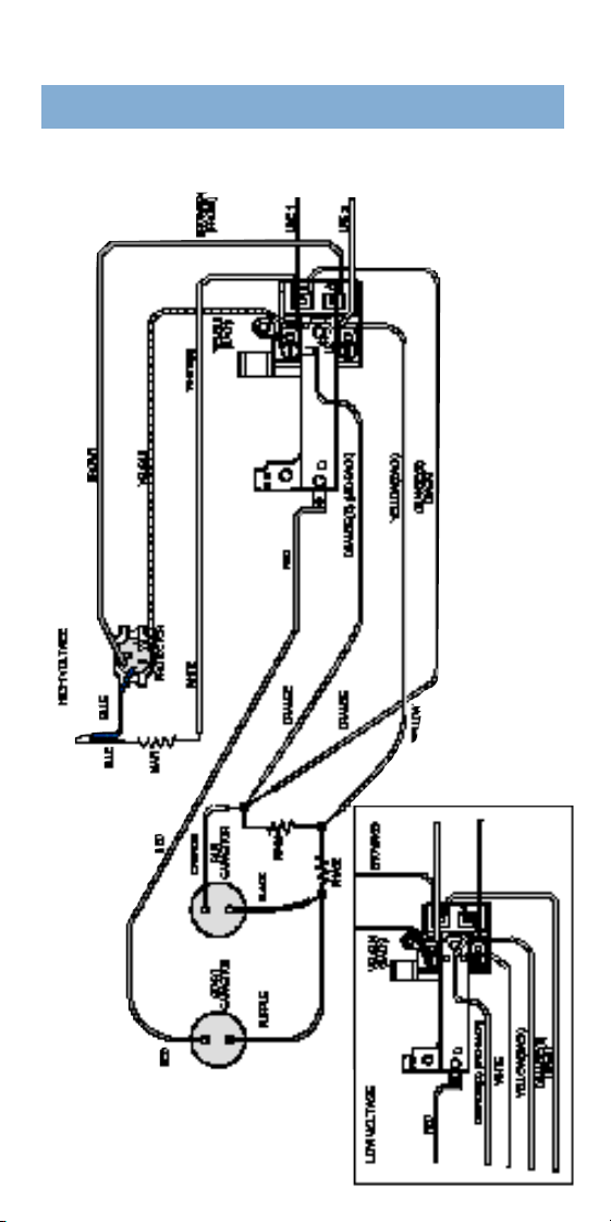
5 7
Dual Voltage Type CP
230/115 Volt
1
⁄
2
-1
1
⁄
2
Hp
N E P T U N E
®
2 Compartment Motors
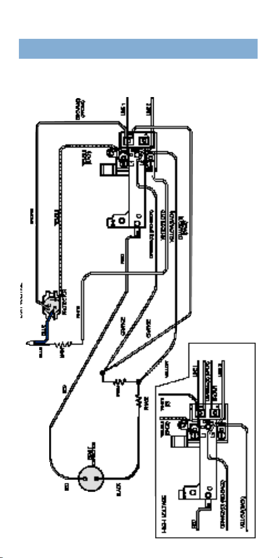
5 8
Dual Vo l t a g e Type CS
230/115 Vo l t
1
⁄
3
- 1
1
⁄
2
H p
N E P T U N E
®
2 Compartment Motors

1
A.O. Smith
531 North Fourth Stre e t
Tipp City, OH 45371
9 3 7 - 6 6 7 - 6 8 0 0
Fax (937) 667-5873
Bulletin 2944
©
A . O . Smith 2000 Litho in USA #2944 11/00