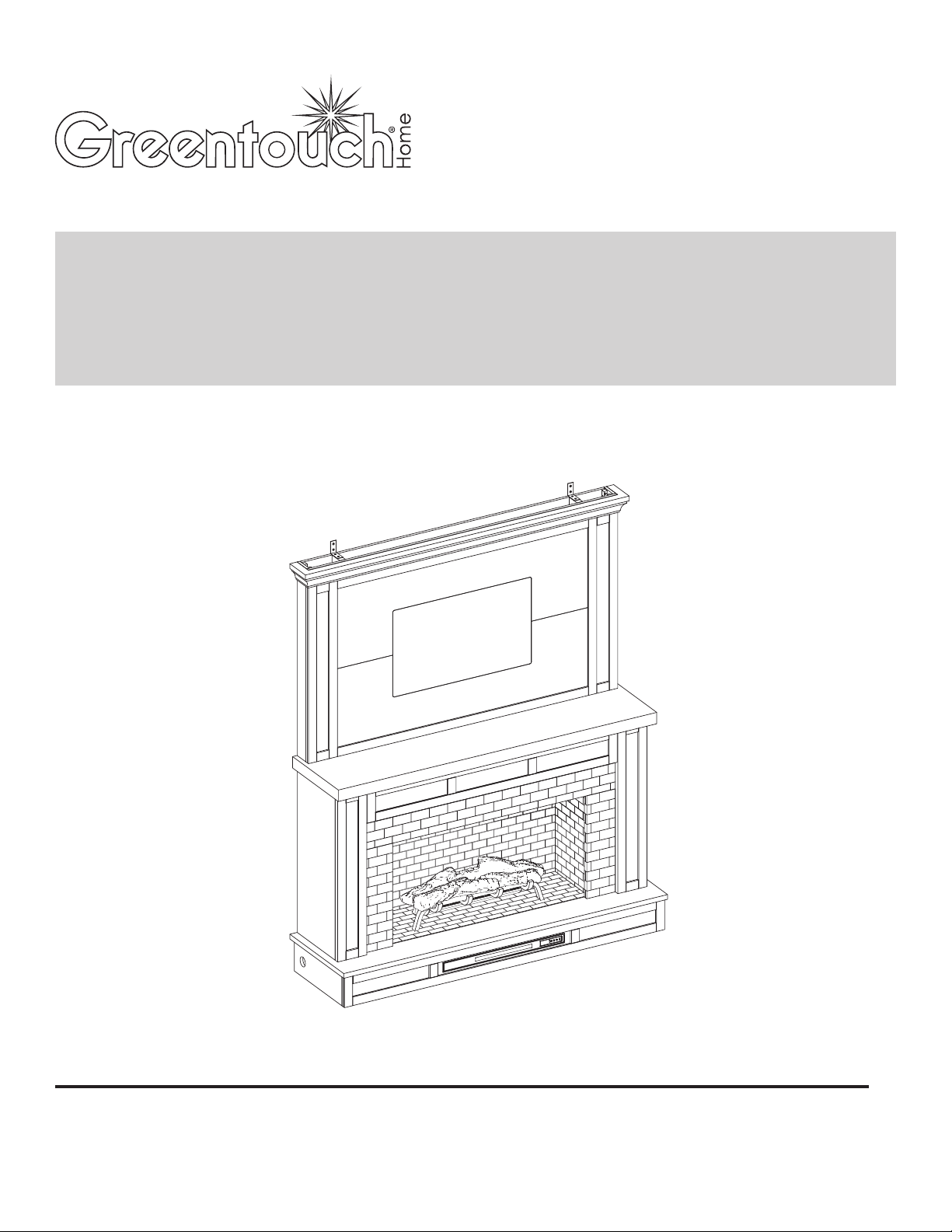
1
MENARDS ITEM #641-5218
MODEL #2486FM-42-319
ATTACH YOUR RECEIPT HERE
70" ELECTRIC FIREPLACE
ENTERTAINMENT CENTER
ASSEMBLY, CARE & USE INSTRUCTIONS
Serial Number__________________ Purchase Date__________________
Questions, problems, missing parts?
Before returning to your retailer, call our customer service department
at 1-855-571-1044 9 a.m. - 5 p.m., EST, Monday - Friday. www.greentouchhome.com.

2
TABLE OF CONTENTS
Package Contents ...........................................................................................................................................................3
Hardware Contents .........................................................................................................................................................4
Safety Information ..........................................................................................................................................................4
Preparation .....................................................................................................................................................................8
Assembly Instructions .....................................................................................................................................................8
CHANGE DOOR PANEL (OPTIONAL) ................................................................................................................................24
Operating Instructions ...................................................................................................................................................25
Care And Maintenance ..................................................................................................................................................27
Troubleshooting ............................................................................................................................................................28
One-Year Limited Warranty ...........................................................................................................................................29
Replacement Parts List .................................................................................................................................................30
3
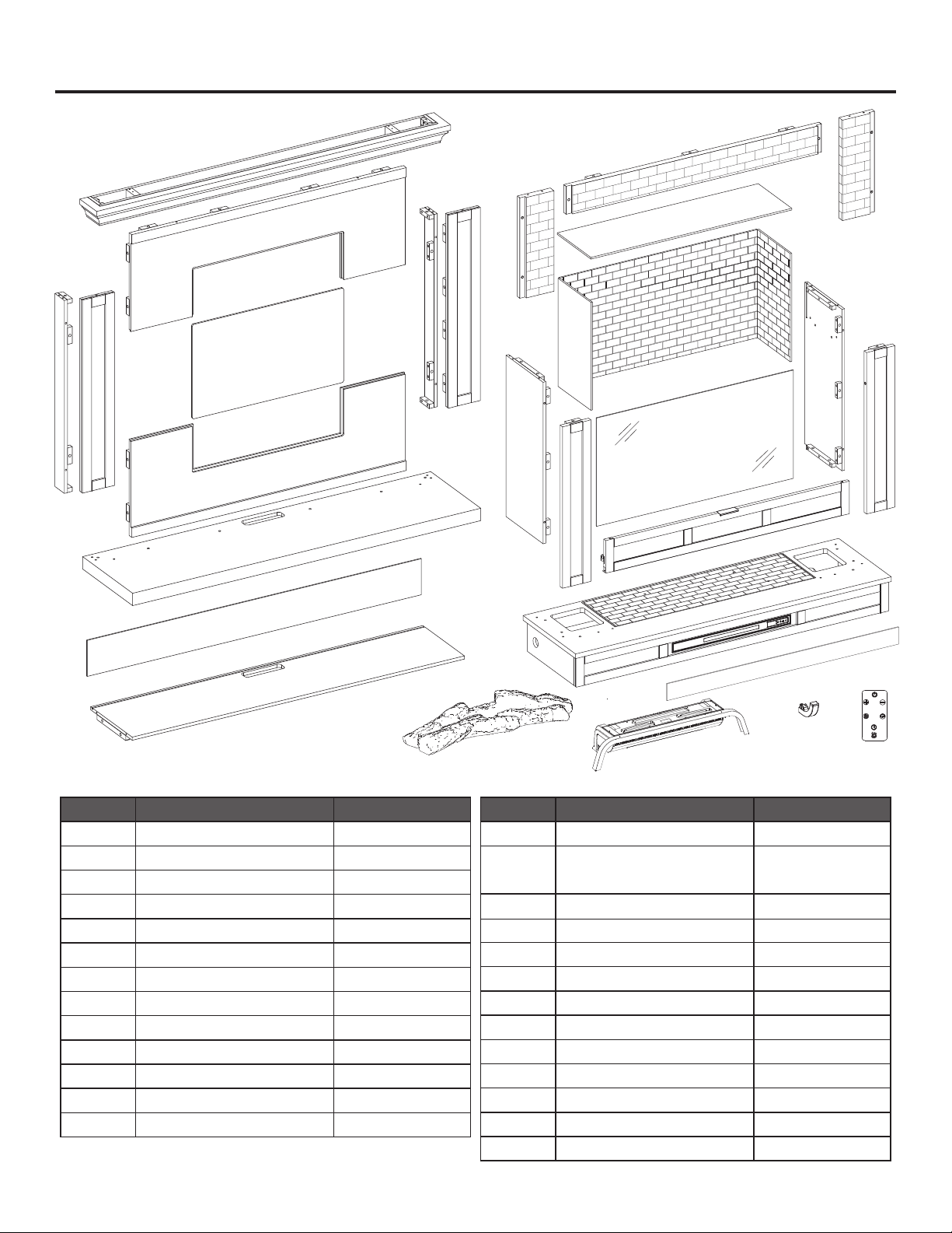
PACKAGE CONTENTS
PART DESCRIPTION QUANTITY
A
Left Wall
1
B
Right Wall
1
C
Left Front Panel
1
D
Right Front Panel
1
E
Center Shelf
1
F
Upper Opening Plate
1
G Left Opening Plate 1
H Right Opening Plate 1
I
Base and Heater
1
J Back Panel 1
K
Top
1
L
Fireplace Glass
1
M
Fireplace Brick Wall
1
PART DESCRIPTION QUANTITY
N
Firebox Top Panel
1
O
Flip-Down Door
1
Wood Door Panel (Optional)
4
Q
Lower Board
Baffle
1
R
Upper Board
1
S
Side Front Panel
1
T
Side Panel
1
U
Top Cover Plate 1
V
W
Cover Panel
2
X
Fireplace Grate
2
Y
Fire Log
1
Z1
Z2
Remote Control (Battery
1
1
Included)
TEMP
Z1
V
W
W
G
H
I
R
T
C
E
L
U
M
O
QN
F
K
D
S
X
X
Y
Z2
A
J
B
4
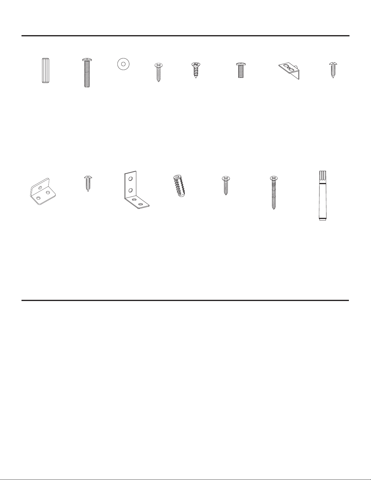
HARDWARE CONTENTS (NOT SHOWN ACTUAL SIZE)
AA BB CC DD EE FF GG HH
II
JJ KK LL MM NN OO
SAFETY INFORMATION
Please read and understand this entire manual before attempting to assemble, operate or install the product.
This equipment has been tested and found to comply with the limits for Class B digital devices, pursuant to Part 15 of
the FCC rules. These limits are designed to provide reasonable protection against harmful interference in a residential
installation. The equipment generates, uses and can radiate radio frequency energy and, if not installed and used
in accordance with the instructions, may cause harmful interference to radio or television reception, which can be
determined by turning the equipment off and on. The user is encouraged to try and correct the interference by one or
more of the following measures:
• Reorient or relocate the receiving antenna
• Increase the separation between the equipment and the receiver
• Connect the equipment into an outlet on a circuit different from that to which the receiver is connected.
• Consult the dealer or an experienced radio/TV technician for help.
This device complies with Part 15 of the FCC rules. Operation is subject to the following two conditions:
1. This device may not cause harmful interference, and
2. This device must accept any interference received, including interference that may cause undesired operation.
Wooden
Dowel x 4
0
Long Bolt
x 57
Washer
x 57
Back Panel
Screw
x 10
L-Bracket
Screws
x 6
Short Screw
x 10
Short Bolt
x 2
Pivot Hinge
x 1
Pivot Hinge
screw
x 2
L-Bracket
x 2
L-Bracket
x 2
Anchor
x 4
Long Screw
x 4
Short Screw
x 4
Touch-up Pen
x 1

5
SAFETY INFORMATION (CONTINUED)
Modifications not approved by the party responsible for compliance could void user’s authority to operate the equipment.
This Class B digital apparatus complies with Canadian ICES-003.
IMPORTANT INSTRUCTIONS
When using electrical appliances, basic precautions should always be followed to reduce the risk of fire, electric shock
and injury to persons, including the following:
DANGER
• Read all instructions before installing or using this heater.
• If the information in this manual is not followed exactly, an electric shock or fire may result causing property damage,
personal injury or loss of life.
• ALWAYS unplug this appliance/furnishing from the electrical outlet before cleaning or servicing.
WARNING
• This appliance is hot when in use. To avoid burns, DO NOT let bare skin touch hot surfaces. Keep combustible
material, such as furniture, pillows, bedding, papers, clothes and curtains at least 3 feet from this appliance and keep
them away from the sides and rear.
• Extreme caution is necessary when any heater is used by or near children or individuals with disabilities and
whenever the fireplace is left operating and unattended.
• DO NOT run cord under carpeting. DO NOT cover cord with throw rugs, runners, or similar coverings.
• DO NOT route cord under furniture or appliances. Arrange cord away from traffic areas and where it will not be
tripped over.
• DO NOT insert or allow foreign objects to enter any ventilation or exhaust opening as this may cause an electric
shock or fire, or damage the appliance.
• This appliance has hot and arcing or sparking parts inside. DO NOT use it in areas where gasoline, paint or
flammable vapors or liquids are used or stored. This fireplace should not be used as a drying rack for clothing.
Christmas stockings or decorations should not be hung in the area of it.
• Use this appliance only as described in the manual. Any other use is NOT recommended by the manufacturer and
may cause fire, electric shock or injury to persons.
• Unplug from outlet before putting on or taking off parts.
• Close supervision is necessary when this furnishing is used by, or near children, invalids, or disabled persons.
• Use this furnishing only for its intended use as described in these instructions. DO NOT use attachments not
recommended by the manufacturer.
• Keep the cord away from heated surfaces.
• Never operate the furnishing with the air openings blocked. Keep the air openings free of lint, hair, and other debris.
• Never drop or insert any object into any opening.
• DO NOT operate where aerosol (spray) products are being used or where oxygen is being administered.
• To disconnect, turn all controls to the off position, then remove plug from outlet.

6
SAFETY INFORMATION (CONTINUED)
• Each surface intended to support a load shall have a corresponding statement in the use instructions specifying the
maximum intended load for that surface in pounds (kilograms).
• Risk of electric shock-connect this furnishing to a properly grounded outlet only. See Grounding Instructions.
• To avoid electric shock, fire, or injury, review the assembly instructions to confirm that the appropriate critical
components and accessories are being used with the furnishing.
• Death or serious injury may occur when children climb on audio and/or video equipment furniture. A remote control or
toys placed on the furnishing may encourage a child to climb on the furnishing and as a result the furnishing may tip
over on to the child.
• Relocating audio and/or video equipment to furniture not specifically designed to support audio and/or video
equipment may result in death or serious injury due to the furnishing collapsing or overturning onto a child.
CAUTION
• DO NOT operate any heater with a damaged cord or plug or after the heater malfunctions. DO NOT operate
any heater if it has been dropped or damaged in any manner. Disconnect power at service panel and have heater
inspected by a reputable electrician before reusing.
• Any repairs to this fireplace should be carried out by a qualified service person.
• Under no circumstances should this fireplace be modified. Parts having to be removed for servicing must be replaced
prior to operating this fireplace again.
• Household use only.
• DO NOT use outdoors.
• “WARNING – Death or serious injury may occur when children climb on audio and/or video equipment furniture. A
remote control or toys placed on the furnishing may encourage a child to climb on the furnishing and as a result the
furnishing may tip over on to the child”.
• “WARNING – Relocating audio and/or video equipment to furniture not specifically designed to support audio and/
or video equipment may result in death or serious injury due to the furnishing collapsing or overturning onto a child”.
• This heater is not intended for use in bathrooms, laundry areas and similar indoor locations. NEVER place heater
where it may fall into a bathtub or other water container.
• To disconnect this appliance, turn controls to the OFF position, then remove plug from outlet.
• ONLY connect to properly grounded outlets.
• This appliance, when installed, must be electrically grounded in accordance with local codes, with the current CSA
C22.1 Canadian Electrical Code or follow U.S.A. Installations, follow local codes and the National Electrical Code, ANSI/
NFPA N0.70.
• To prevent a possible fire, DO NOT block air intakes or exhaust in any manner. DO NOT use on soft surfaces, like
a bed, where opening may become blocked.
• The heaters MUST NOT be located immediately below a socket-outlet.
• ALWAYS plug heaters directly into a wall outlet / receptacle. NEVER use with an extension cord, re-loadable
power tap (outlet / power strip) or a smart outlet.
• DO NOT slide insert on top of wood to avoid scratching wood surface.
• DO NOT place any object on top of the insert or block the air intakes / vents as this can cause the unit to overheat
and could cause a fire.
7
SAFETY INFORMATION (CONTINUED)
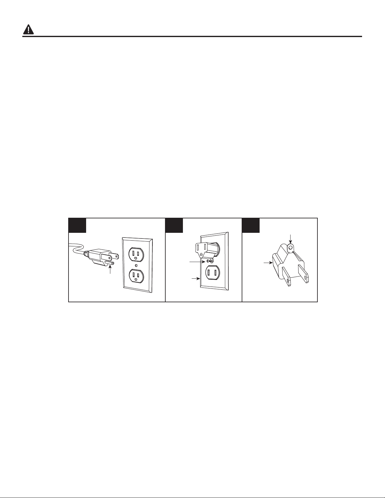
Electrical Connection
• A 15-Amp, 120-volt, 60 Hz circuit with a properly grounded outlet is required. Preferably, the fireplace will be on a
dedicated circuit as other appliances on the same circuit may cause the circuit breaker to trip or the fuse to blow
when the heater is in operation. The unit comes standard with 6-ft. three-wire cord, exiting from the rear of the
fireplace. DO NOT exceed the current rating of the current tap.
Grounding Instructions
• This heater is for use on 120 volt. The cord has a plug as shown below. See illustration or grounding instruction. An
adapter as shown at C is available for connecting three-blade grounding type plugs to two-slot receptacles. The green
grounding plug extending from the adapter must be connected to a permanent ground such as a properly grounded
outlet box. The adapter should not be used if a three-slot grounded receptacle is available.
A B C
Grounding Pin
Grounding Means
Metal
Screw
Cover of
Grounding
Box
Adapter
SAVE THESE INSTRUCTIONS
8
PREPARATION
Before beginning assembly of product, make sure all parts are present. Compare parts with package contents list and
hardware contents list. If any part is missing or damaged, do not attempt to assemble the product.
Estimated Assembly Time: 80 minutes
Tools Required for Assembly (not included): Phillips screwdriver.
Note: Must use a “Full-Motion TV Mount” (not included). Fixed and tilting TV mounts CANNOT be used with this
mantel. There are many types and shapes of TV mounts, the TV mount shown in the drawings is for reference only.
ASSEMBLY INSTRUCTIONS
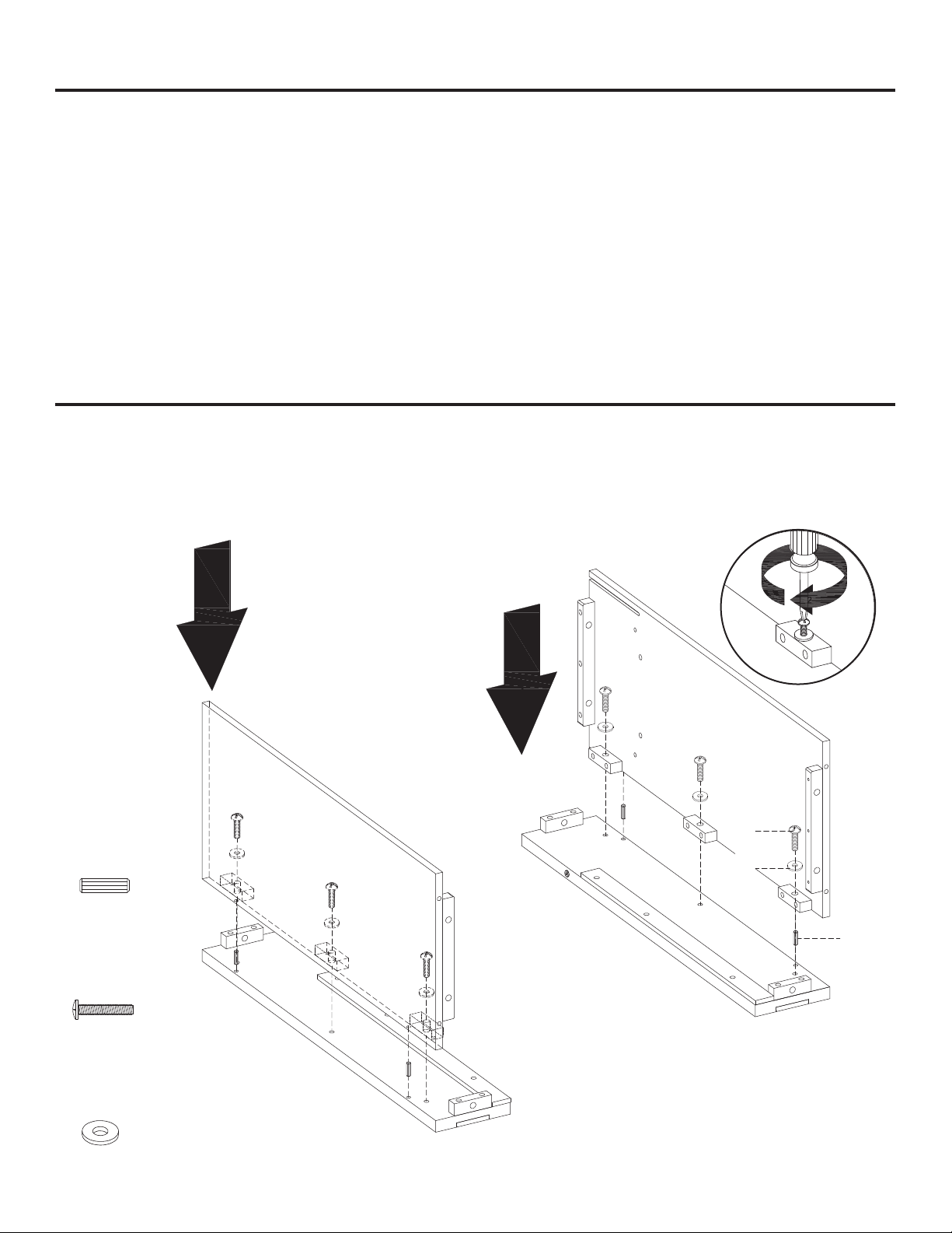
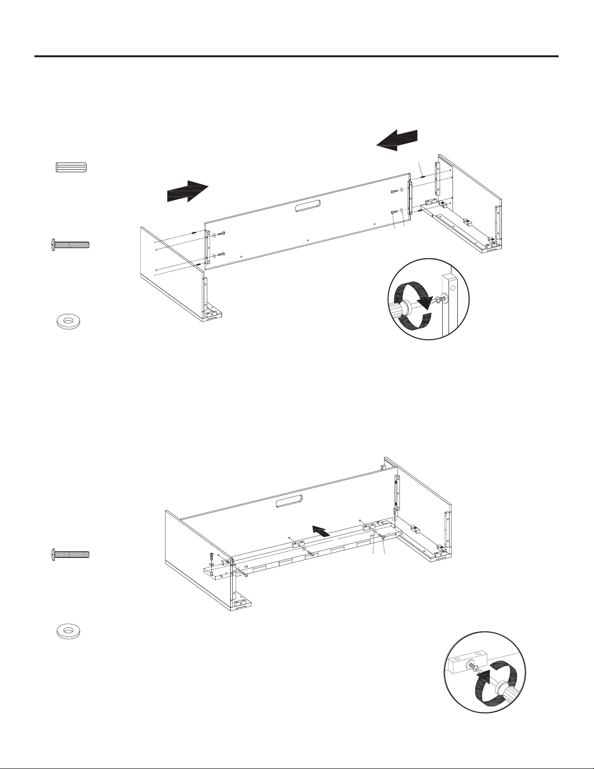
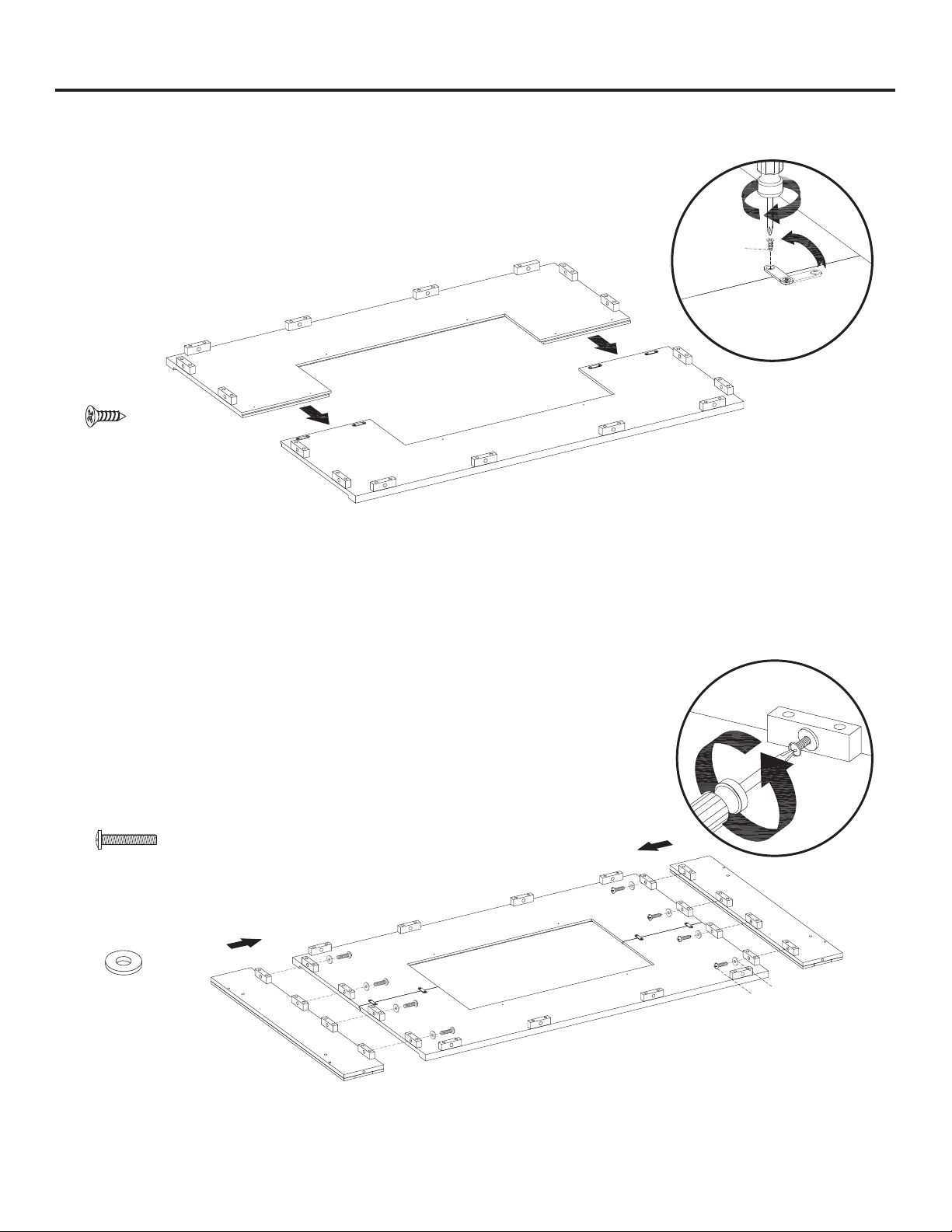
1. Attach the left wall (C) to the left front panel (E) using 4 wood dowels (AA). Secure with 3 long bolts (BB) and
washers (CC), using a phillips head screwdriver. Repeat for the right wall (D) and right front panel (F).
C
E
F
BB
CC
D
BB
AA
Long Bolt
x 6
CC
Washer
x 6
AA
Wood Dowel
x 4
9
ASSEMBLY INSTRUCTIONS (CONTINUED)
2. Attach the center shelf (B) to the right wall (D), using 4 wood dowels (AA). Secure with 2 long bolts (BB) and
washers (CC) using a phillips head screwdriver. Repeat for the left wall (C).
3. Align and attach the upper opening plate (I) to the assembled panels from Step 2. Secure with 5 long bolts (BB),
and washers (CC) using a phillips head screwdriver.
BBCC
I
BB
Long Bolt
x 4
CC
Washer
x 4
AA
Wood Dowel
x 4
BB
Long Bolt
x 5
CC
Washer
x 5
2
C
AA
BB
CC
D
B
1
1
10
ASSEMBLY INSTRUCTIONS (CONTINUED)
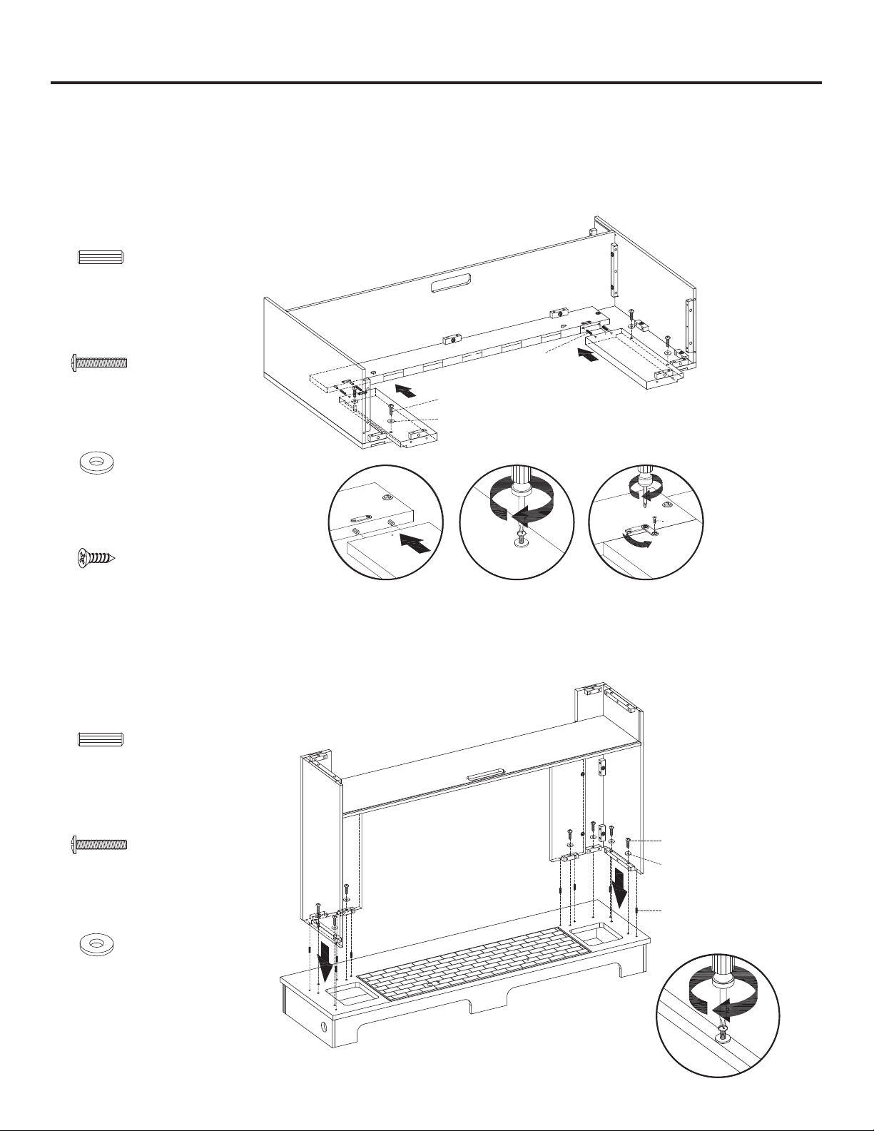
4. Insert four wooden dowels (AA) into the bottom holes of the upper opening plate (I), align and attach the opening
plates (G, H) to the upper opening plate (I). Adjust the metal plate on the opening plates (G, H) to align with the
corresponding holes on the upper opening plate (I), securing with two screws (EE).
Attach the left and right opening plates (G, H) to the upper opening plate (I) with four wood dowels (AA).
Secure with 4 long bolts (BB), washers (CC) and short screws (EE), using a phillips head screwdriver.
5. Attach the assembly from Step 4 onto the base (U), using 8 wood dowels (AA). Secure with 8 long bolts (BB) and
washers (CC) using a phillips head screwdriver.
BB
Long Bolt
x 4
CC
Washer
x 4
AA
Wood Dowel
x 4
BB
Long Bolt
x 8
CC
Washer
x 8
AA
Wood Dowel
x 8
EE
Short Screws
x 2
2
BB
AA
EE
CC
H
G
U
1
2
3
1
1
2
BB
AA
CC
11
ASSEMBLY INSTRUCTIONS (CONTINUED)
6. As shown in the diagram, insert the back panel (J) along the grooves of the walls (C, D).
C
J
D
A
7. Attach the top (A), using 4 wood dowels (AA). Secure from underneath with 6 bolts (BB) and washers (CC),
using a phillips head screwdriver.
BB
BB
CC
Long Bolt
x 6
CC
Washer
x 6
AA
AA
Wood Dowel
x 4
1
2
12
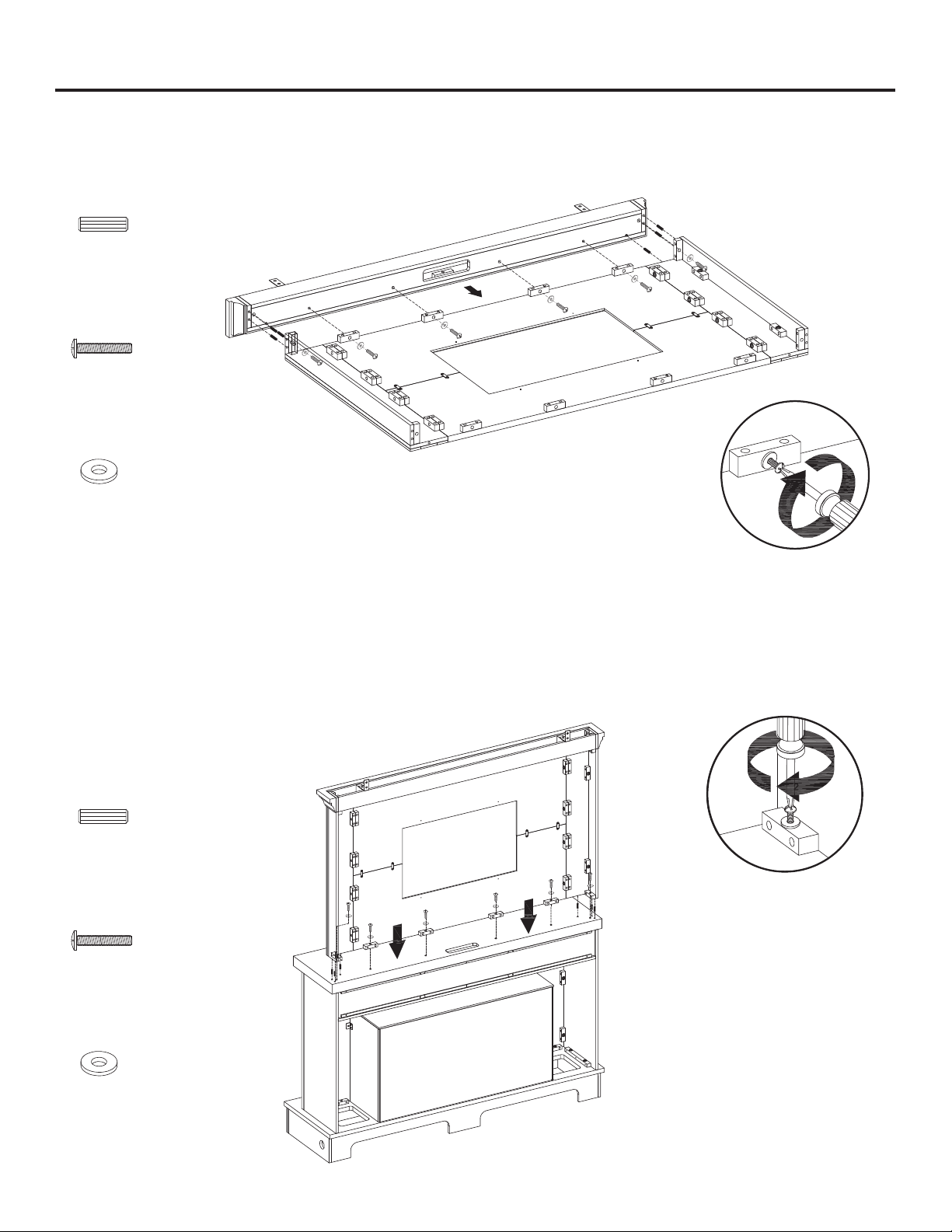
ASSEMBLY INSTRUCTIONS (CONTINUED)
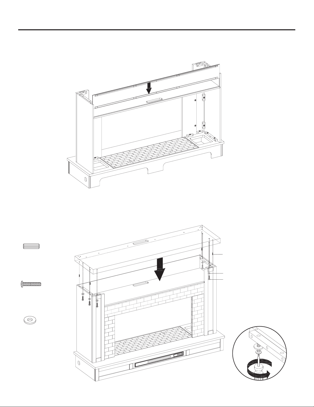
8. Secure the back panel (J) to the product with the back panel screws (DD), using a phillips head screwdriver.
9. Insert the fireplace glass front (T) into the assembled panels from the back side. Carefully lower the fireplace glass
front (T) into the groove on the base (U). Secure the glass into place by turning the pre-assembled plastic knobs.
Feed the USB cable from the heater underneath through the cable hole on the base.
DD
J
DD
T
U
Back Panel Screws
x 10
2
13
ASSEMBLY INSTRUCTIONS (CONTINUED)
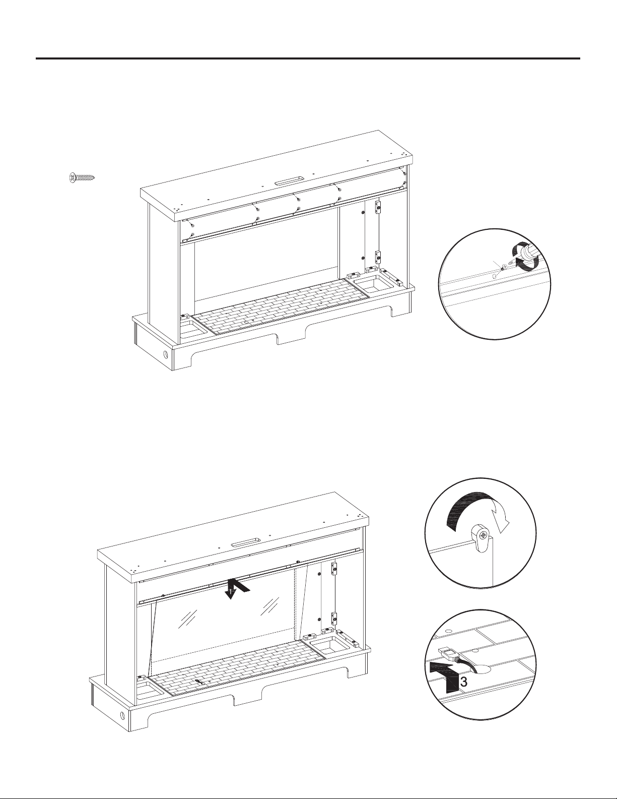
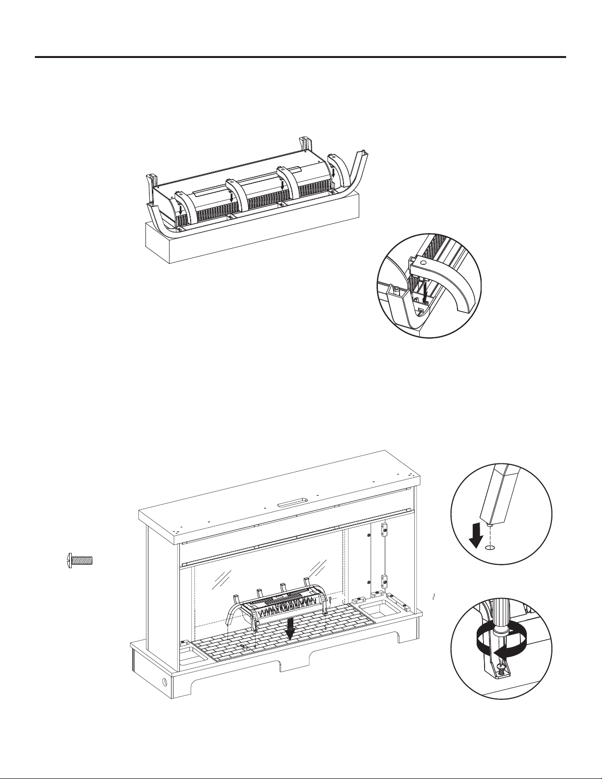
10. Insert the baffles (Q) into the fireplace grate (N) as shown in the diagram.
BOX
N
N
FF
Q
11. Install the fireplace grate (N) by inserting the bottom pins into the holes in the base (U). Secure with two short bolts
(FF) using a phillips head screwdriver.
1
2
FF
Short Bolt
x 2
14
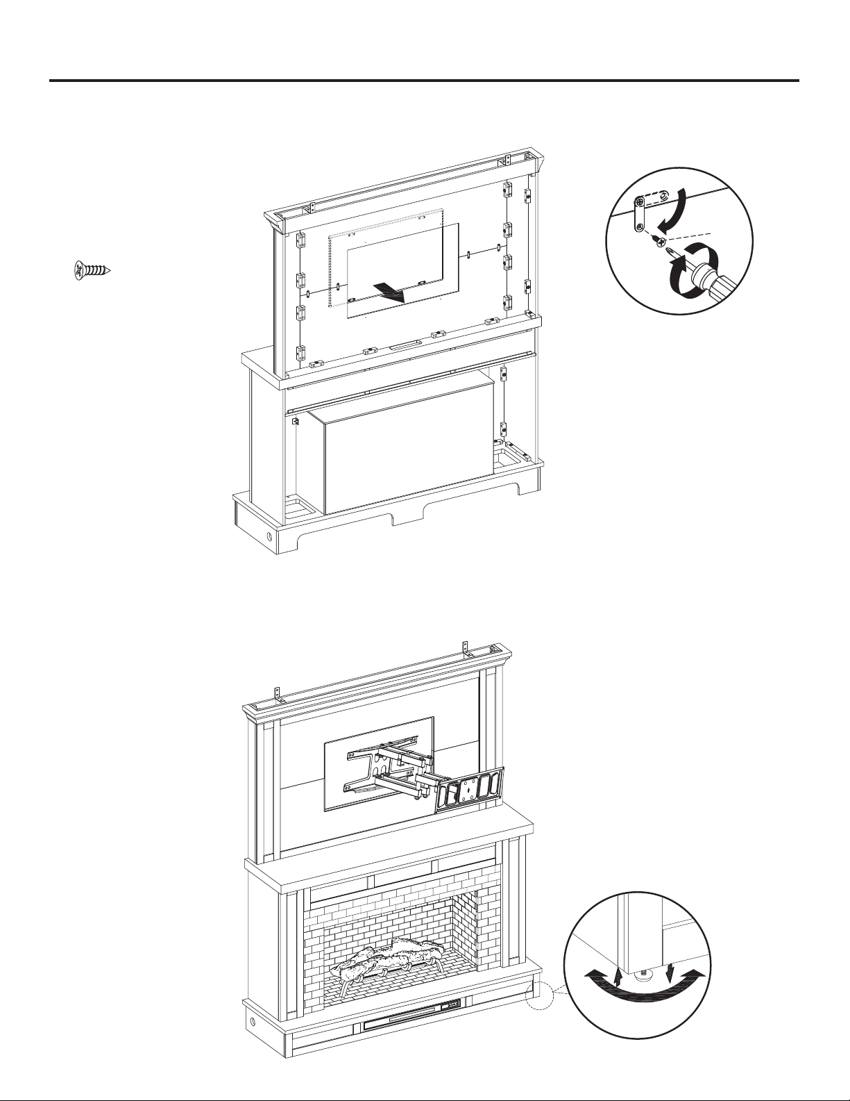
ASSEMBLY INSTRUCTIONS (CONTINUED)
12. Remove the film from the adhesive on the top of the fireplace grate (N) and place the fire log (M) on the center of the
fireplace grate (N). Attach the USB cable from the heater into the USB port behind the fireplace grate (N).
M
S
JJ
II
13. Unfold the fireplace brick wall (S) and mount L-brackets (II) with L-bracket screws (JJ), using a phillips
1
2
3
II
L-Bracket
x 2
JJ
L-Bracket
Screws
x 4
head screwdriver.
15
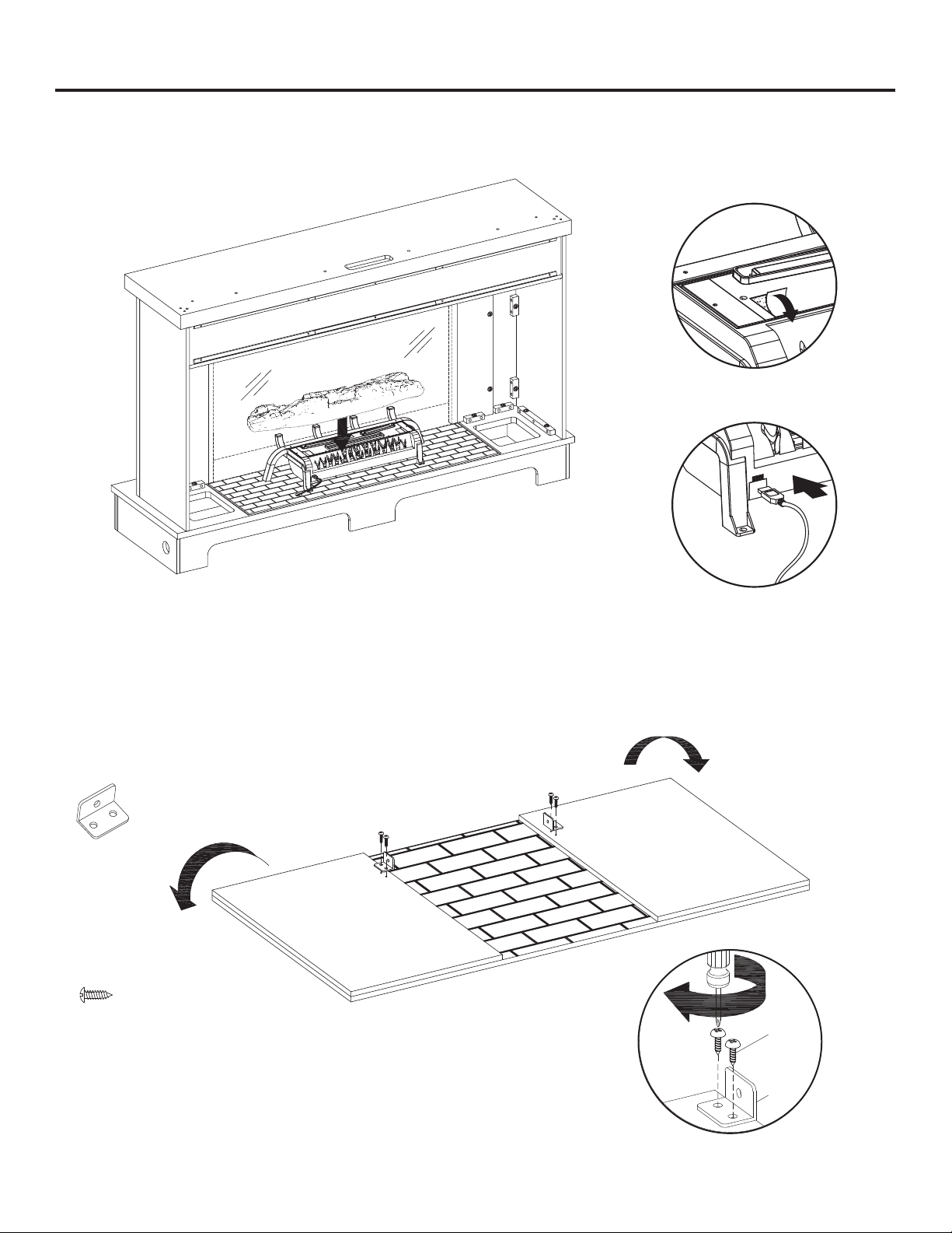
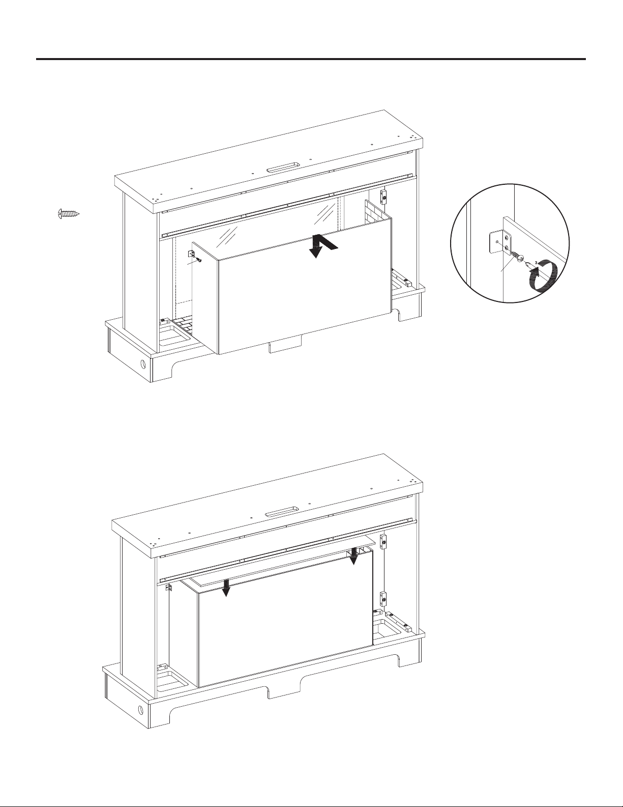
ASSEMBLY INSTRUCTIONS (CONTINUED)
14. Insert the fireplace brick wall (S) into the mantel, slotting it into the grooves on the base (U). Fasten the brackets to
the back side of the opening plates (G, H) using two screws (EE) into the bracket.
15. Place the firebox top panel (R) on top of the firebox with the corner bumpers facing inward.
JJ
JJ
JJ
S
R
L-Bracket
Screws
x 2
1
16
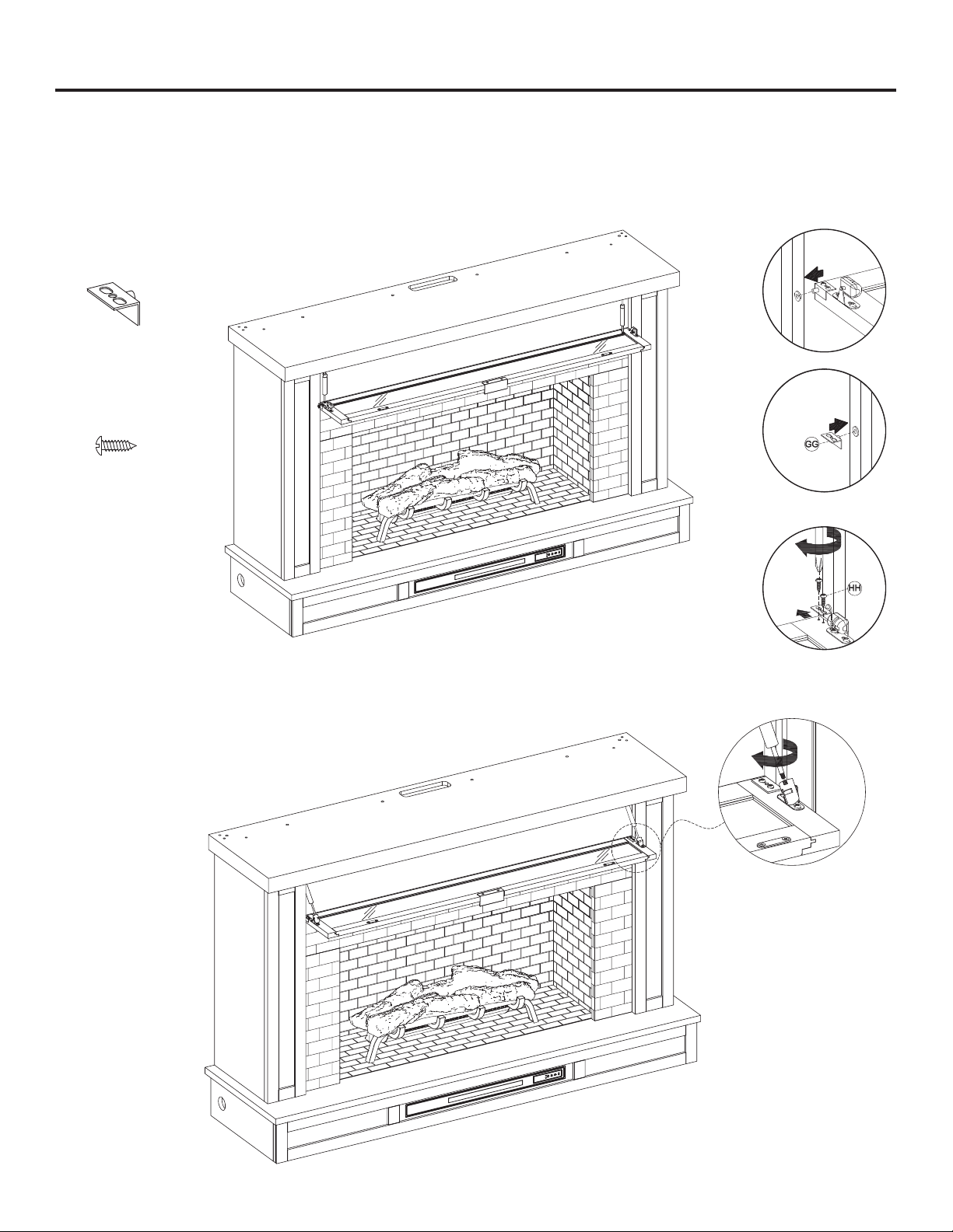
ASSEMBLY INSTRUCTIONS (CONTINUED)
16. Hold the flip-down door (K) horizontally with the hinge side up, insert the pin of the left hinge to the plastic female
thread on bottom left of the opening. Take the pivot hinge (GG) from the hardware bag and insert the pin of the hinge
into the right side plastic female thread on the right bottom corner. Align the pivot hinge screws (HH) to the
pre-drilled screw holes on the corner of the flip-down door (K), secure the pivot hinge (GG) with two pivot hinge
screws (HH).
K
17. Screw the two hydraulic rods to the door by twisting them clockwise, and securing the flip-down door.
GG
Pivot Hinge
x 1
HH
Pivot Hinge
Screw
x 2
2
3
1
2
1
17
ASSEMBLY INSTRUCTIONS (CONTINUED)
18. Align and attach the boards (Z1, Z2), adjust the metal plate on the lower board (Z2) to align with the corresponding
holes on the upper board (Z1), securing with four short screws (EE).
2
3
1
1
EE
Short Screw
x 4
19. Align and attach the side front panels (X) to the left and right sides with the assembly from Step 18, secure with
screwing 8 long bolts (BB) and washers (CC) with a phillips head screwdriver.
1
1
Z1
Z2
EE
BB
BB
CC
Long Bolt
x 8
CC
Washer
x 8
2
X
X
18
ASSEMBLY INSTRUCTIONS (CONTINUED)
20. Attach the side panels (W) to the side front panels (X) with 4 wood dowels (AA). Secure with four bolts (BB)
and washers (CC) using a phillips head screwdriver.
21. Screw two L-bracket (KK) onto the top of the top cover plate (V) using four short screws (MM).
MM
V
KK
W
BB
CC
AA
W
KK
L-Bracket
x 2
MM
Short Screw
x 4
BB
Long Bolt
x 4
CC
Washer
x 4
AA
Wood Dowel
x 4
19
ASSEMBLY INSTRUCTIONS (CONTINUED)
22. Attach the top cover plate (V), securing from underneath with 6 wood dowels (AA), 6 long bolts (BB) and 6 washers (FF).
1
23. Lift the panel assembled in Step 22 onto the back of the mantel top, place it on the top edge of the top (A). Align the
holes of the top (A) and secure the assembled panels using 6 wood dowels (AA), long bolts (BB), and washers (CC). (FF).
At least 2 adults are required in this step as the assembled panels are heavy.
If TV is not being installed please continue. If installing a TV please skip to Step 25.
BB
Long Bolt
x 6
CC
Washer
x 6
AA
V
Wood Dowel
x 6
BB
Long Bolt
x 6
CC
Washer
x 6
AA
Wood Dowel
x 6
2
1
1
2
20
ASSEMBLY INSTRUCTIONS (CONTINUED)
24. Align and attach the cover panel (Y), adjust the metal plate on the cover panel (Y) to align with the corresponding
holes on the boards (Z1,Z2), securing with four short screws (EE).
EE
2
3
Y
25. NOTE: Use the pre-assembled levelers on the base of the fireplace to level the unit. Twist the levelers
counter-clockwise to increase the height, twist clockwise to decrease the height.
1/2 in.
1
EE
Screw
x 4
21
ASSEMBLY INSTRUCTIONS (CONTINUED)
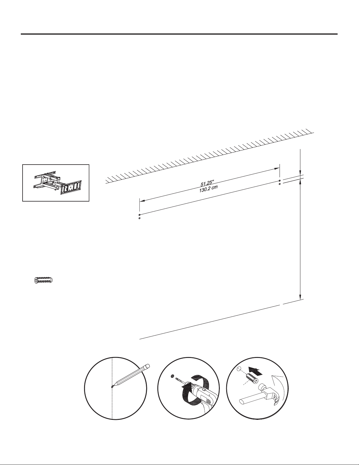
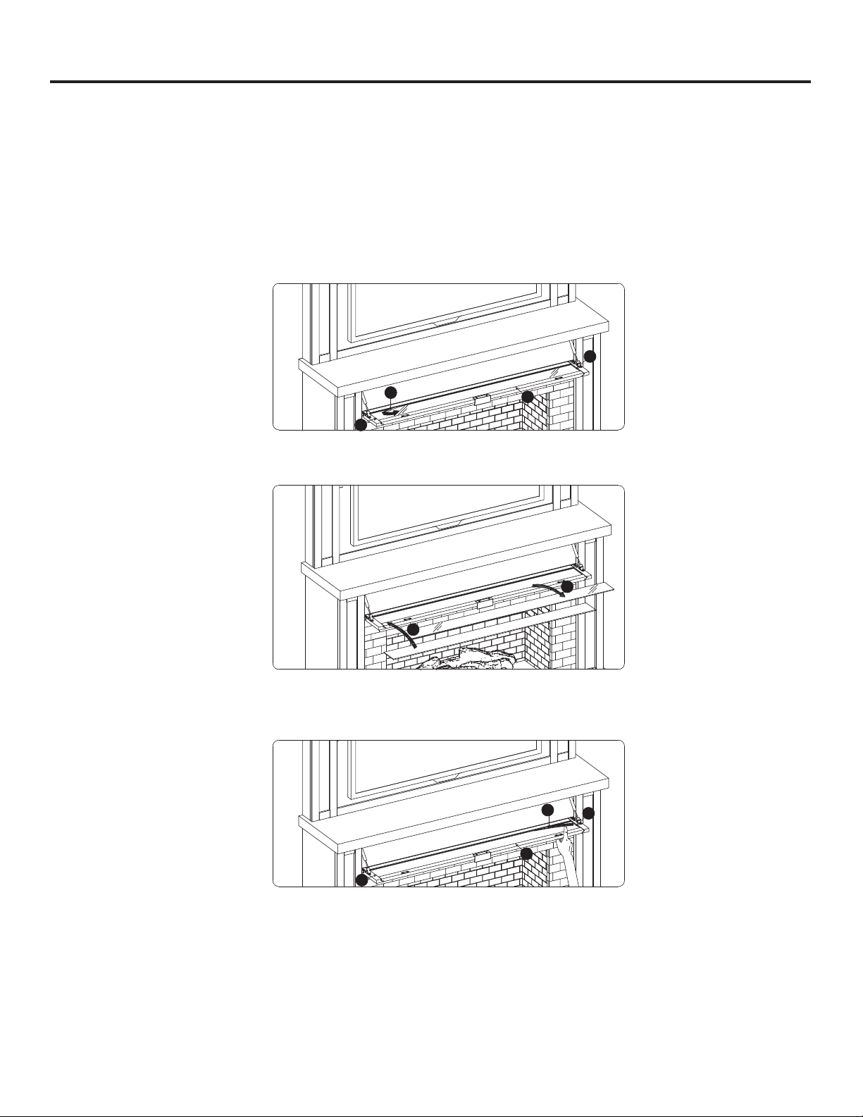
26. Move the mantel into its final position on the wall. Use a pencil or paint tape to mark the location for mounting
hardware on the wall as a guide. Make sure the marks are level and located at the desired height.
Move the mantel away from the wall and drill guide holes for the marked points of the L-bracket on the wall and
insert the anchor (LL) flush into the wall. Use the marking you made as a guide for location of the TV mount. Follow
the TV mount manufacturer’s instructions for proper installation.
Note: Must use a “Full-Motion TV Mount” (not included). Fixed and tilting TV mounts CANNOT be used with this
mantel. There are many types and shapes of TV mounts, the TV mount shown in the drawings is for reference only.
1
LL
Note:
Opening size is
30 in w x 18 in h
TV Mount
Not Included
84.34''
215.4 cm
1.2''
3 cm
LL
Anchor
x 4
2
22
ASSEMBLY INSTRUCTIONS (CONTINUED)
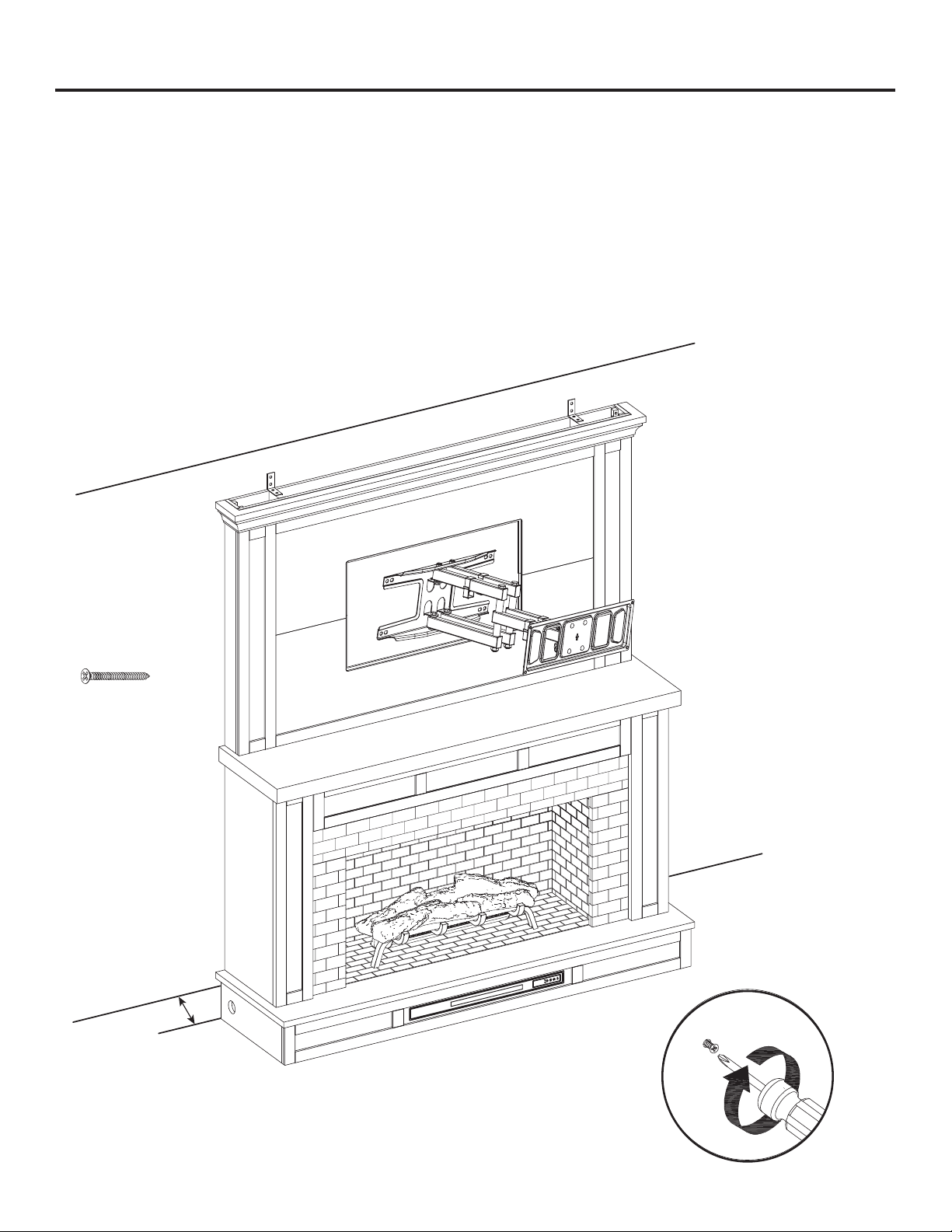
27. With TV mount fully extended, move mantel closer to wall and guide TV mount through opening in panel.
Leave a gap between the mantel and the wall approximately 6-10 inches to allow access to run TV power and AV
cables behind the mantel.
Mount the TV onto the bracket, then feed the TV power and AV cables from the TV through the opening behind the
mantel accordingly.
Note: Check to make sure the TV and all AV equipment work as expected before moving mantel into final position
against the wall.
6-in to 10-in
Gap from Wall
NN
Long Screw
x 4
23
ASSEMBLY INSTRUCTIONS (CONTINUED)
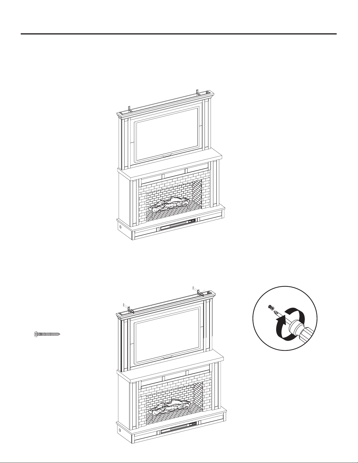
28. This is a good time to plug the fireplace into the power outlet. With the TV installed, get the help of another person
to careful push the mantel into it’s final desired position against the wall. Take care not to pinch or crush any cords
behind the unit. If the TV bracket is still extended, carefully push the TV back into place against the mantel so the TV
bracket is compressed and the TV is in the desired location.
Note: Fits up to most 139.7 cm / 55 in flat panel TVs.
29. Align the holes of the L-bracket with the anchor inserted into the wall, and secure the L-bracket with four long
screws (NN).
WARNING: You must install the L-bracket to help prevent any accidents or damage to the unit.
NN
NN
Long Screw
x 4
24
CHANGE DOOR PANEL (OPTIONAL)
Note: The pre-installed glass door panel can be switched out with the included wood door panel (L).
1. Remove the silicone trim along the outer edges of the glass panel on the inside of the flip down door. Start at a corner
and pull to remove the four pieces. Be careful not to damage the silicone trim as it will be used to secure the new
panel.
2. Remove the glass panel from the door frame, then insert the included wood door panel (L).
3. Using your finger press the silicone trim back into place. Move around the outer edge of the panel until all four sides
are secure.
3
1
4
2
1
2
P
3
1
4
2
3
2
1
25
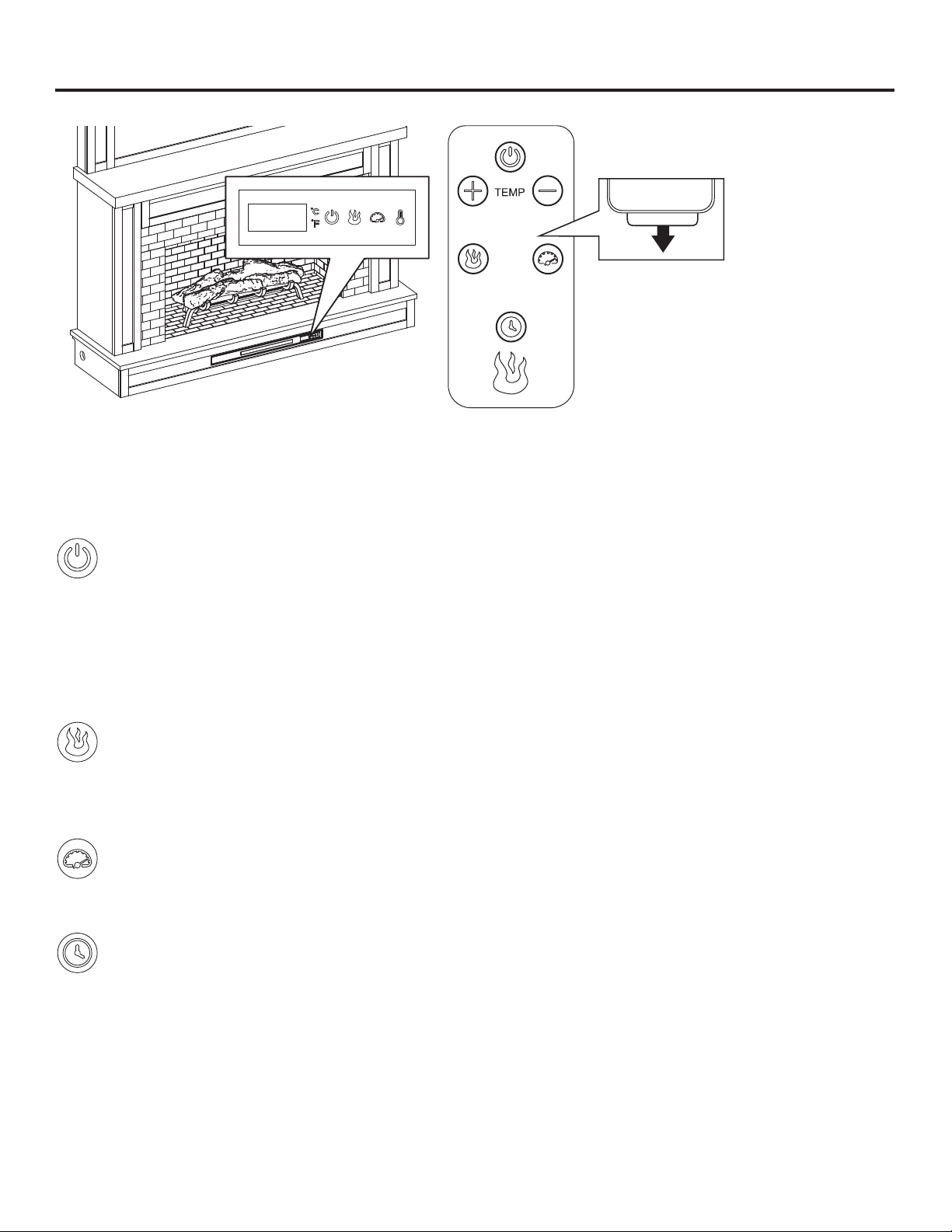
OPERATING INSTRUCTIONS
Control Panel Remote Control
To use the remote control, first remove the
plastic tab by gently pulling it out of remote
control.
Controls and Display
The control panel will display the heater setting when the unit power is turned ON. Whichever control icon you press will
display the current setting of the corresponding function. Press the control icon again to adjust the setting. Following
adjustment of any setting(s), the unit will resume to display the heater setting after 5 seconds.
Power Function
• When the unit is plugged-in but not in use, F or C will illuminate to indicate that it is in stand-by mode.
• Press the POWER ICON to turn the main power to the unit ON or OFF.
• When the unit is powered ON, the control panel will display the heater setting to indicate the unit has power.
• Functions stored in memory will resume at the last setting.
• When the unit is powered OFF, the fan will continue to blow for a 40 second cool-down cycle prior to shutting
down (a countdown will be displayed).
Flame Brightness Function
• Press the FLAME BRIGHTNESS ICON to display the current flame brightness setting.
• Press the FLAME BRIGHTNESS ICON again to scroll down through the flame brightness settings:
5, 4, 3, 2, 1, oF (OFF).
Flame Speed Function
• Press the FLAME SPEED ICON to display the current flame speed setting.
• Press the FLAME SPEED ICON again to scroll down through the flame speed settings: 5, 4, 3, 2, 1.
Sleep Timer Function (Remote Control Only)
• The Sleep TIMER function will set a countdown to shut down the unit’s main power.
• Press the TIMER ICON to display the current Sleep Timer setting.
• Press the TIMER ICON again to scroll through the timer settings, which are: 30 (minutes), 1H, 2H, 3H, 4H, 5H,
6H, 7H, 8H, 9H, oF (OFF).
• When the timer reaches zero, it will turn OFF the main power and will maintain all the settings in memory.

26
OPERATING INSTRUCTIONS (CONTINUED)
Heater Function (Control Panel Only)
• Press the HEATER ICON to display the current heater setting.
• Press the HEATER ICON again to scroll down through the heater settings.
Note: Long-hold the icon to quickly scroll through settings.
• Set the heater to “HI” (High) to have the heater run continually.
• Set the heater to “oF” (OFF) to use the flame functions without heat.
• This heater has a thermostat sensor to control the ambient temperature in the surrounding area of the
fireplace. The heater will cycle ON and OFF to maintain the selected temperature. The thermostat setting
range is 90ºF (32°C) to 65°F (18°C), HI (High) and oF(OFF).
Note: This may not exactly match the room thermostat reading as their sensors are located in different
areas.
• Hold down the FLAME SPEED ICON for 10 seconds to toggle between Fahrenheit and Celsius. “F” or “C” will
be displayed on the control panel (°F/°C can only be toggled from the control panel and will not work if using
the remote control).
• See HEATER OVERRIDE section to disengage the heater.
Adjusting the Heater Setting from the Remote Control
• You can scroll upwards or downwards through the heater settings using the remote control for added
convenience.
• Press the PLUS ICON to scroll upwards through the heater settings.
• Press the MINUS ICON to scroll downwards through the heater settings.
HEATER OVERRIDE
The power to the heater can be disengaged to prevent the heater from being accidentally or unintentionally powered on.
This feature is primarily added to help prevent children from powering on the heater when it is not desired.
Note: The heater override can only be set from the control panel and will not work if using the remote control.
• First turn the main power OFF. Press the POWER ICON; as the heater setting display is flashing, press the POWER ICON
again and long-hold 20 seconds. The E3 symbol will display to indicate that the heater is now disengaged.
• Note: The Flame and Timer functions will operate normally. Only the heater is disengaged.
• Repeat the same process to re-engage the heater function. The E3 symbol will change back to display the heater
setting when the heater is re-engaged.
MEMORY FUNCTION
• This unit has a memory function that allows you to turn off the MAIN POWER and retain all the other function settings
(excluding the SLEEP TIMER function).
27
CARE AND MAINTENANCE
• Make sure the unit is turned OFF, unplugged and the heating elements of heater are cool whenever you are cleaning
the heater or fireplace.
• Clean the metal trim using a water-dampened soft, clean cloth. DO NOT use brass polish or household cleaners as
these products will damage the metal trim.
• The motors used on the fan and the flame generator assembly are pre-lubricated for extended bearing life and
require no further lubrication. However, periodic cleaning/vacuuming of the fan/heater and air intake/output vents are
recommended.
• When the heater is not in use, the power cord should be stored properly to avoid contact with hot or sharp objects.
• Tips for using touch-up pen (OO): For scratches, stroke in direction of scratch. For worn areas, stroke in the direction of
wood grain. Rub excess colorant promptly with a soft cloth.
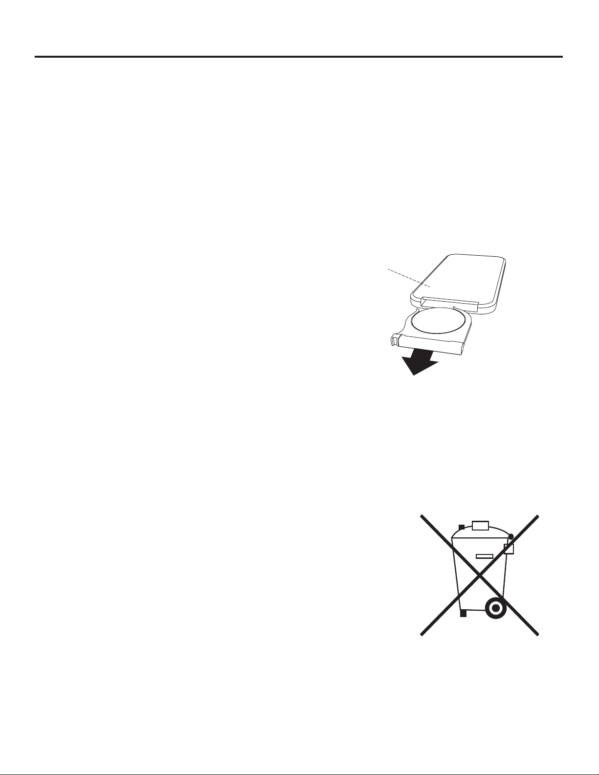
Replacing the Remote-Control Battery
When the remote control (O) stops operating or its range seems
reduced, it is time to replace the battery. Note: The battery should
be removed if the product is to be left unused for a long time.
1. The battery compartment is located on the back end of the
remote control (O).
2. Press the small tab inward as you slide the battery door open
and remove the old battery.
3. Insert a new CR2025 lithium battery (not included), checking
that the + and - sides of the battery match the inside of the
battery compartment.
4. Re-insert the battery door.
BATTERY
O
Note: Non-rechargeable battery is not to be recharged. Exhausted battery is to be removed from the product.
Harmful if swallowed.
Disposal of Used Battery
A battery may contain hazardous substances that could be endangering the environment and human health.
• This symbol marked on the battery and/or packaging indicates that used
battery shall not be treated as municipal waste. Instead it shall be left at the
appropriate collection point for recycling.
• By ensuring the used battery is disposed of correctly, you will help prevent
potential negative consequences for the environment and human health. The
recycling of materials will help to conserve natural resources.
• Do not dispose of battery in fire. Battery may explode or leak.
For more information about collection and recycling of used battery, please contact
your local municipality, your waste disposal service or the point-of-sale where you
purchased this battery.

28
TROUBLESHOOTING
PROBLEM POSSIBLE CAUSE CORRECTIVE ACTION
Error E1 displayed on
control panel.
The overheat sensor has
been engaged.
Unplug unit, wait 15-20 minutes, then the sensor will reset
itself. Plug the unit back in and turn on the heater. If the problem
persists, call customer service (1-855-571-1044).
Note: The other functions will work normally excluding the heater.
Error E2 displayed on
control panel.
The thermostat sensor
is broken or not working
correctly.
Unplug unit, wait 15-20 minutes, then the sensor will reset
itself. Plug the unit back in and turn on the heater. If the problem
persists, call customer service (1-855-571-1044).
Note: The other functions will work normally excluding the heater.
Error E3 displayed on
control panel.
Heater override function is
engaged.
See page 26 Heater Override Section for more details.
No power. The unit does not have
power.
Check that the power cord is securely plugged into a standard
120V outlet. Then check to make sure the unit is powered on.
No flame effect but the
unit is powered on.
The flame effect is powered
off.
Push the flame brightness button until desired level is achieved.
USB cable. Connect the USB cable into the USB port behind the Fireplace
Grate.
Heater and blower do
not power on but rest of
functions are working.
Heater setting. Set the heater to "HI" (High) to have the heater run continually.
Power cord gets warm
to the touch.
Normal operation. This is normal for a heater appliance as it requires more current
to operate. Check the connections of the appliance cord and the
outlet. Make sure the plug fits tightly into the outlet. During use,
check the plug and outlet frequently to determine if it is HOT; if
so, discontinue use of the appliance and consult with a qualified
technician to check or change the overheating outlet(s).
Remote control does not
work.
Weak or failing battery. Replace with 1 CR-2025 battery (See page 27 for more
information).
Remote control signal
is weak and only work
sometimes.
Pressing the buttons too
quickly.
Press the buttons slowly and steadily to ensure the transmitter
recognizes the request.
Using the remote control too
far away or at an off angle.
Move closer to the insert; the remote control will only work within
a distance of 20 feet and 45 degrees to either side from the front
of the fireplace insert.
Fan motor continues to
blow after the unit is
powered off.
Normal operation. This is a standard feature; the blower runs for an additional time
to cool off the heater tubes.

29
ONE-YEAR LIMITED WARRANTY
The manufacturer warrants that your new electric fireplace is free from manufacturing and material defects for a period of
one year from date of purchase, subject to the following conditions and limitations.
Install and operate this electric fireplace in accordance with the installation and operating instructions furnished with the
product at all times. Any unauthorized repair, alteration, willful abuse, accident, or misuse of the product shall nullify this
warranty.
This warranty is non-transferable, and is made to the original owner, provided that the purchase was made through an
authorized supplier of the product.
The warranty is limited to the repair or replacement of part(s) found to be defective in material or workmanship, provided
that such part(s) have been subjected to normal conditions of use and service, after said defect is confirmed by the
manufacturer’s inspection.
The manufacturer may, at its discretion, fully discharge all obligations with respect to this warranty by refunding the
wholesale price of the defective part(s).
Any installation, labor, construction, transportation, or other related costs/expenses arising from defective part(s), repair,
replacement, or otherwise of same, will not be covered by this warranty, nor shall the manufacturer assume responsibility
for same.
The owner/user assumes all other risks, if any, including the risk of any direct, indirect or consequential loss or damage
arising out of the use, or inability to use the product, except as provided by law.
All other warranties-expressed or implied-with respect to the product, its components and accessories, or any obligations/
liabilities on the part of the manufacturer are hereby expressly excluded.
The manufacturer neither assumes, nor authorizes any third party to assume on its behalf, any other liabilities with
respect to the sale of the product.
The warranties as outlined within this document do not apply to non-accessories used in conjunction with the installation
of this product.
This warranty is void if:
1. The fireplace is subjected to prolonged periods of dampness or condensation.
2. Any unauthorized alteration, willful abuse, accident, or misuse of the product.
3. You do not have the original receipt of purchase.
30
REPLACEMENT PARTS LIST
For replacement parts, call our customer service department at 1-855-571-1044 9 a.m. - 5 p.m., EST, Monday - Friday.
www.greentouchhome.com.
QQPP
M
N
O
P
Q
T
RR SS TT VV XX
M
Fireplace Glass Front
Fire Log
Fireplace Grate
Remote Control
PU-1106x560-GLASS FRONT
N
KDI-02-26-319-M
RC-HE85EL02
O
P
Q
T
PP KD Hardware Pack PH-2486FM-42-319-HARDWARE PACK
QQ Flip-Down Door Handle PU-1860HW-04-BN HANDLE
RR
Flip-Down Door Hardware Set PU23-2468FM-LL/MM/NNSS
TT
VV Glass Clips GLASS CLIPS
XX Leveler T-1007
GRATE D
GRATE D BAFFLE
Heater-white
Baffle
FIRE LOG 4
PART DESCRIPTION PART #
TEMP