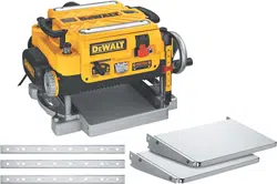

FOXBC Spiral Helical Cutterhead for DeWalt DW735
DW735X DW735XE 13 Inch Planer
User Manual
www.FOXBC.com
2
Helical Cutterhead for Dewalt
DW735 Planer
Getting Started:
Be sure that your machine is
disconnected from its power source
Be careful not to damage any of the
carbide inserts while assembling and
installing the head into the machine.
Use a rubber mallet, dead blow
hammer, or a block of wood with a
regular hammer when tapping the
cast housing.
Blow or brush off the woodchips
from the machine and clean the
floor around the machine to help
eliminate any possible slip hazard.
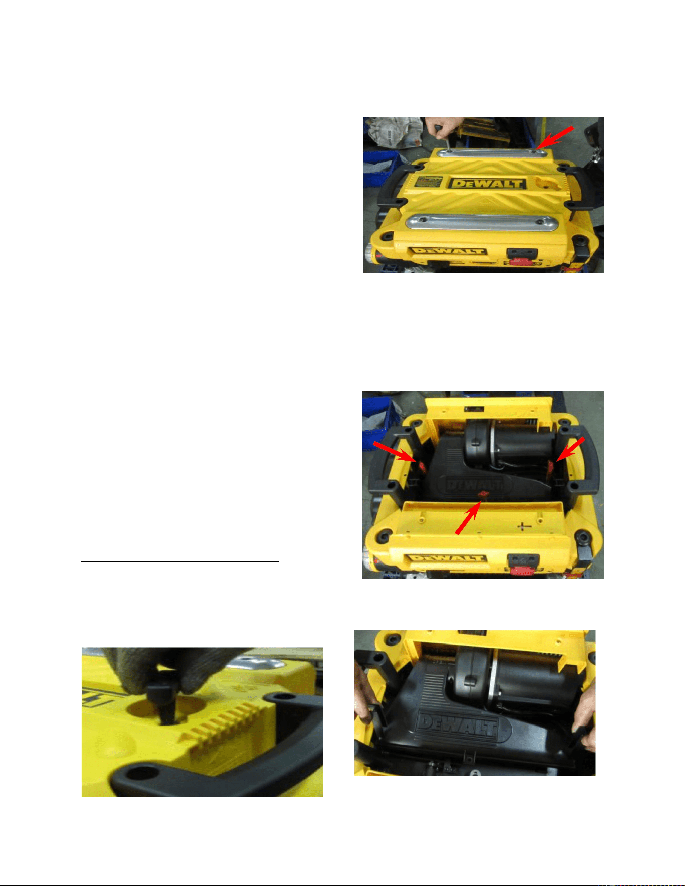
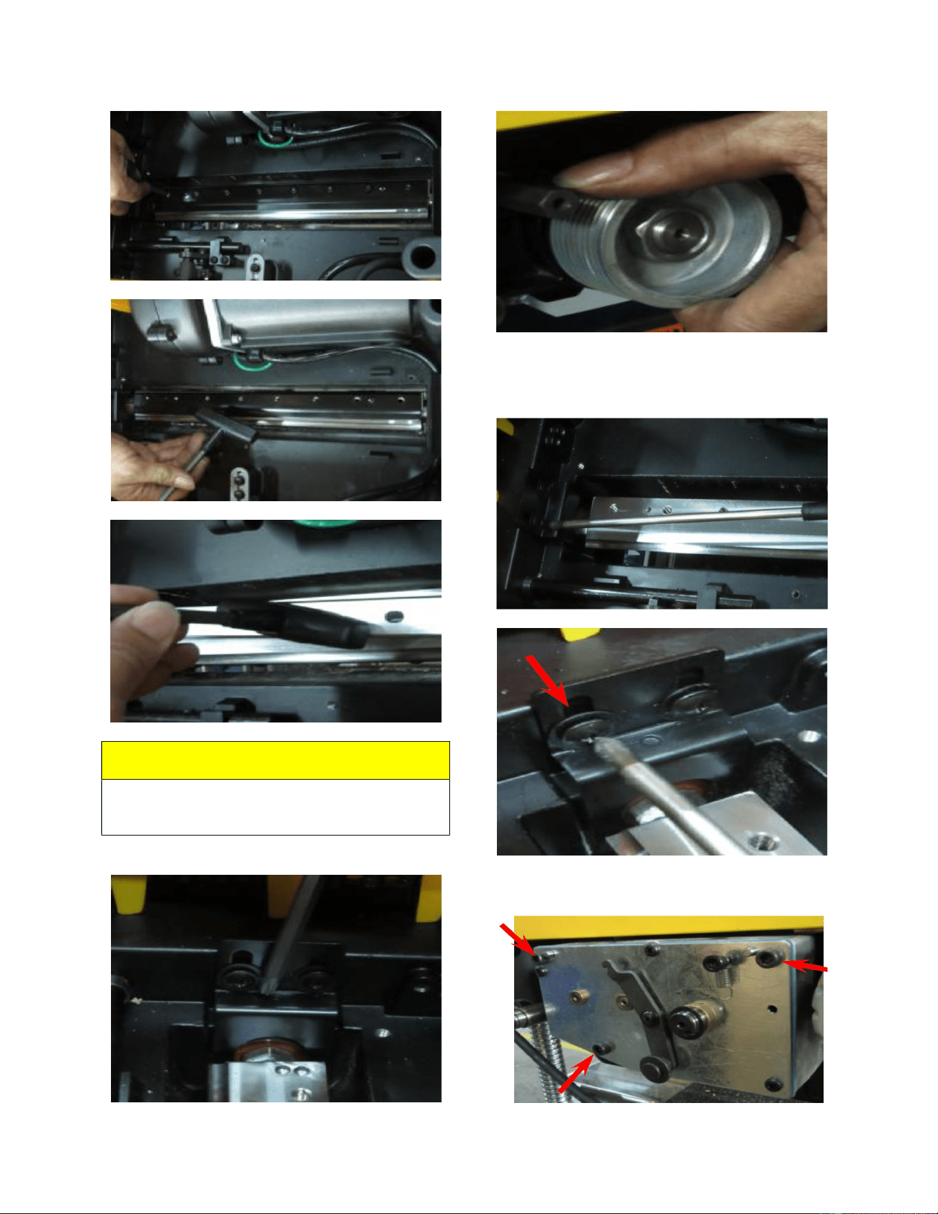
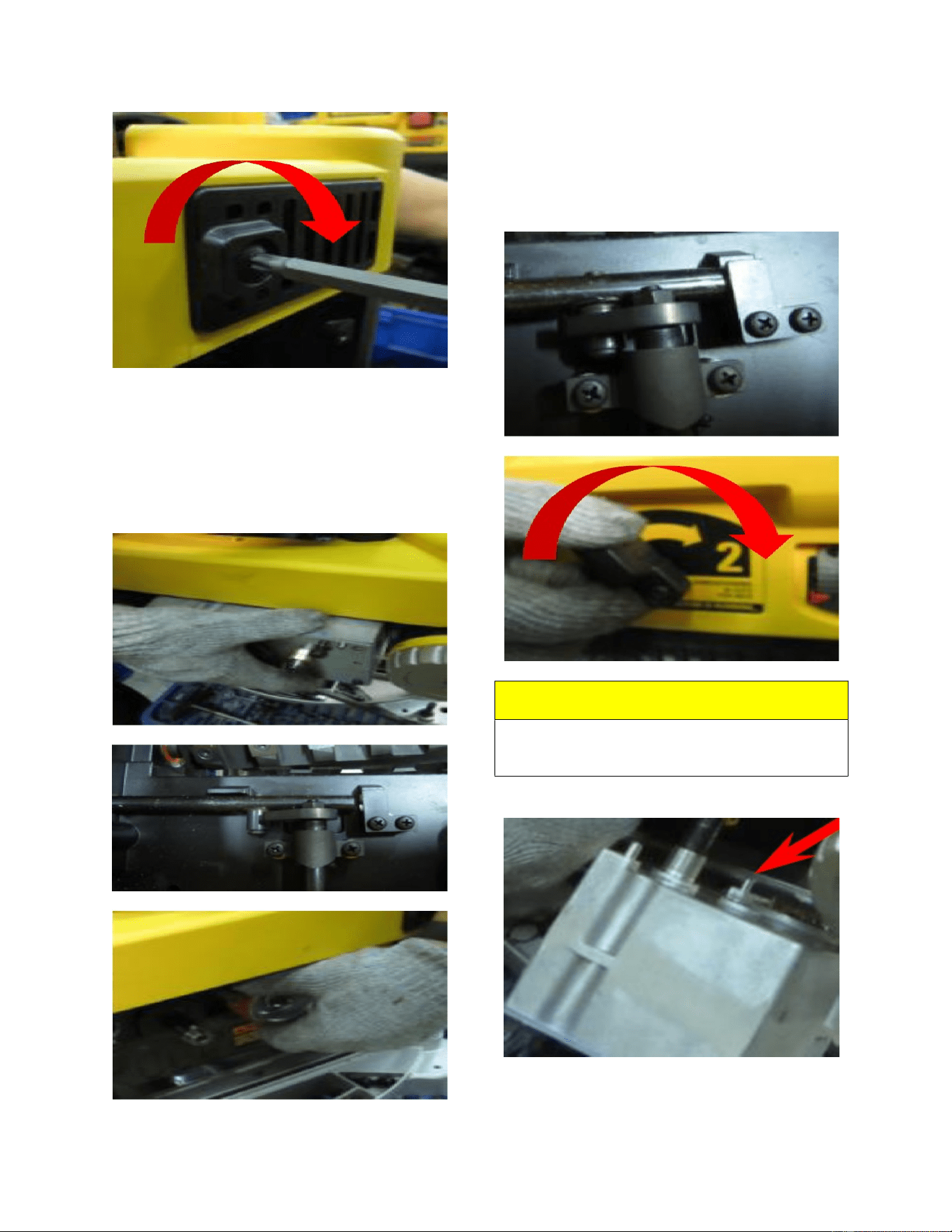
ASSEMBLY INSTRUCTIONS:
1.) Take the top cover off the
planer after removing the 4 screws with
the supplied hex wrench.
2.) Remove the 3 red thumb
screws from the inside of the top. Now
you can remove the inside dust cover.
This will now leave the cutterhead
exposed.
3.) Remove the dust collection
port.
3
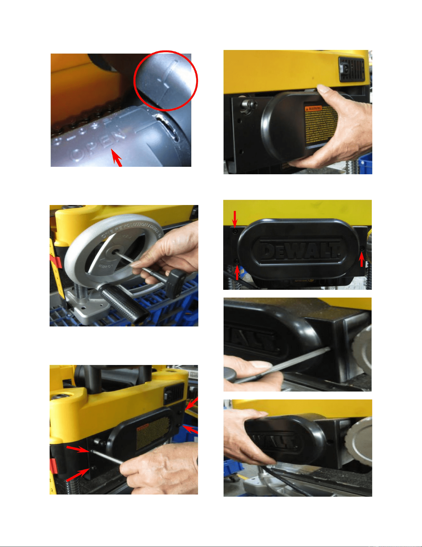
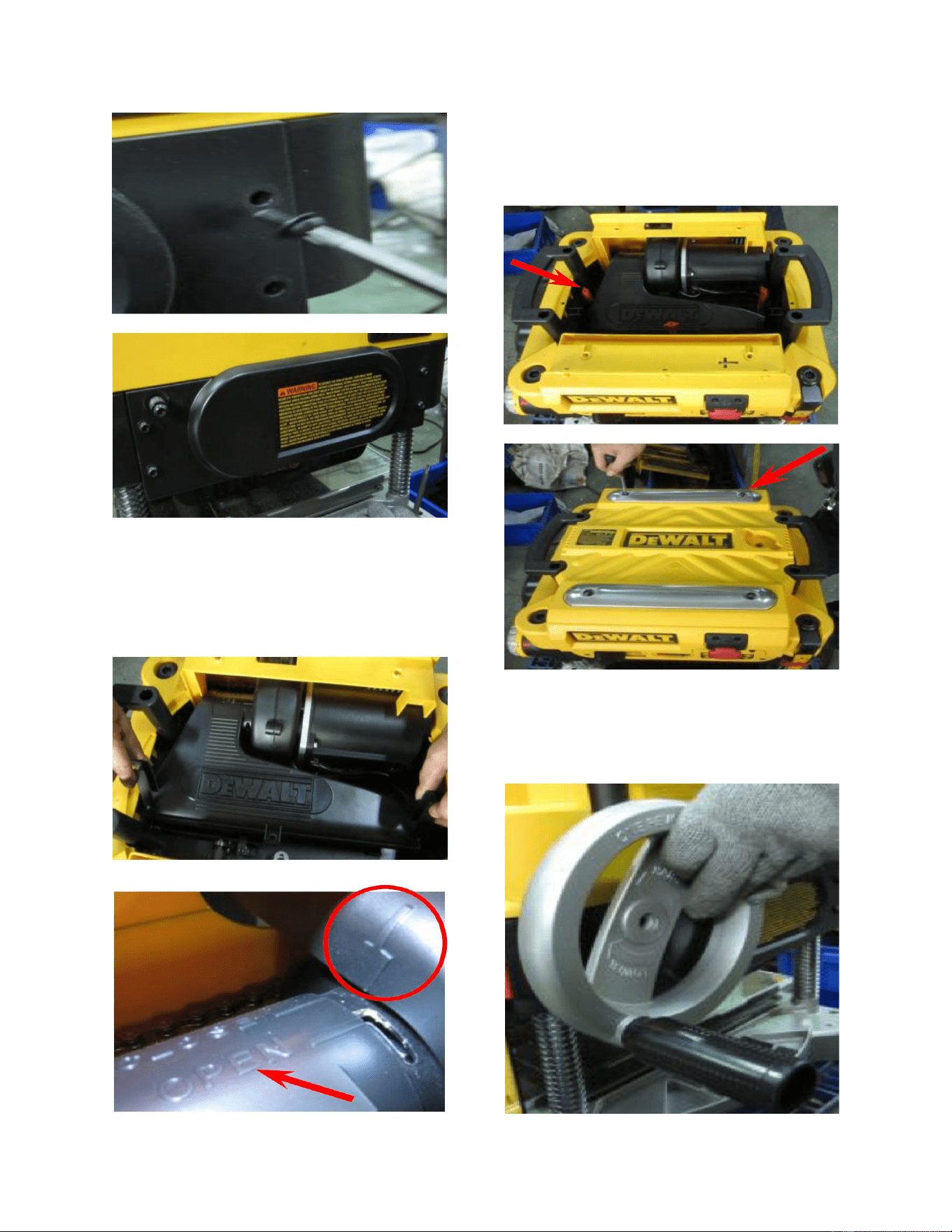
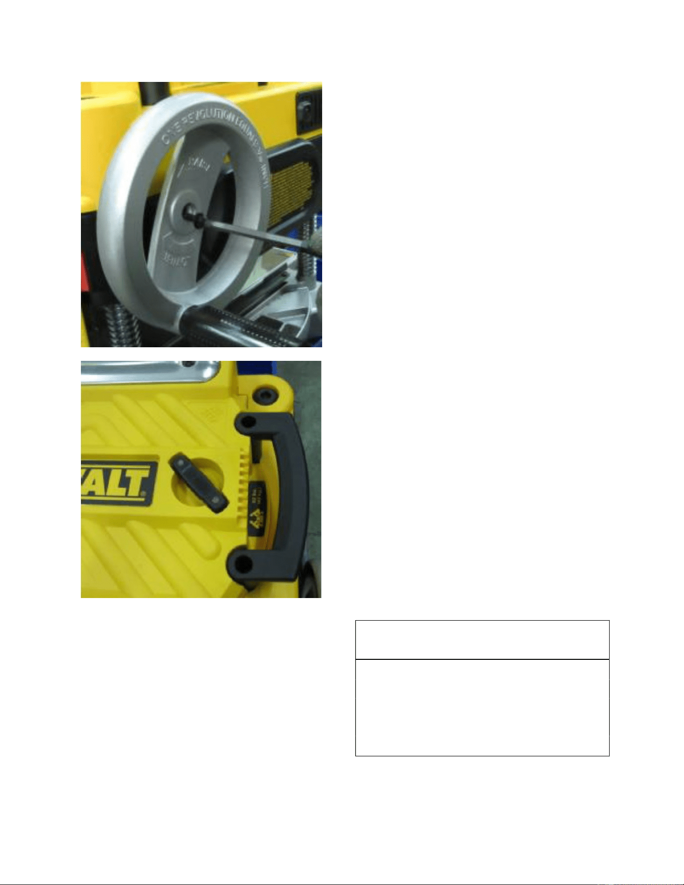
4.) Remove the crank wheel
located on the side of the planer
5.) Remove the right side panel.
6.) Remove the left panel.
4
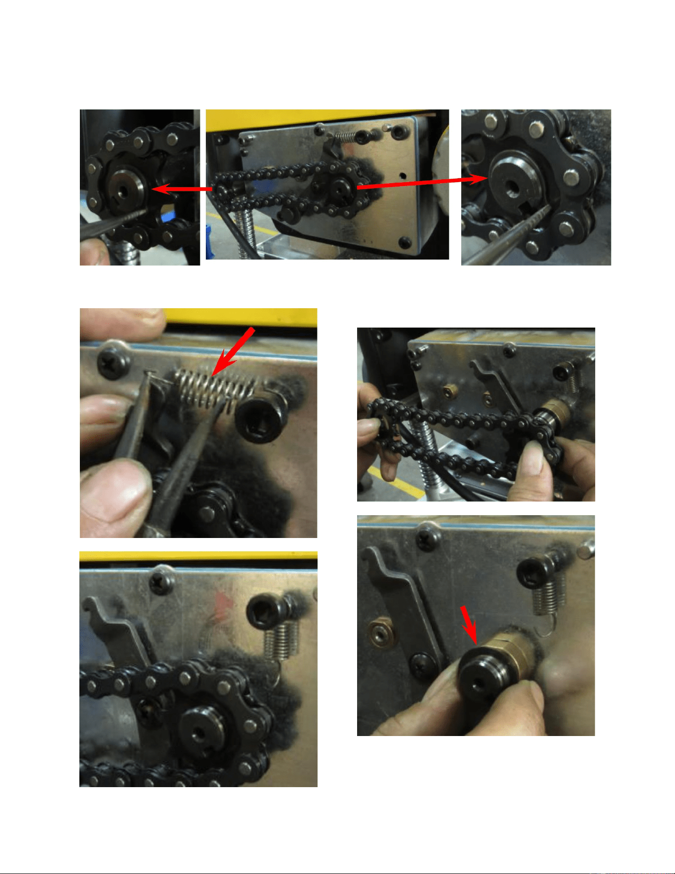
7.) Remove the snap rings for both front and rear rollers.
8.) Remove the spring.
9.) Remove both the sprocket
and the chain. Now remove the spacer.
10.) Remove the tension wheel
assembly.
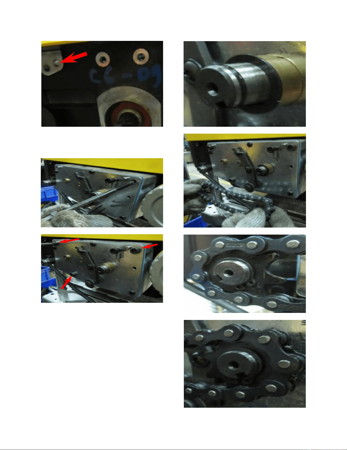
5
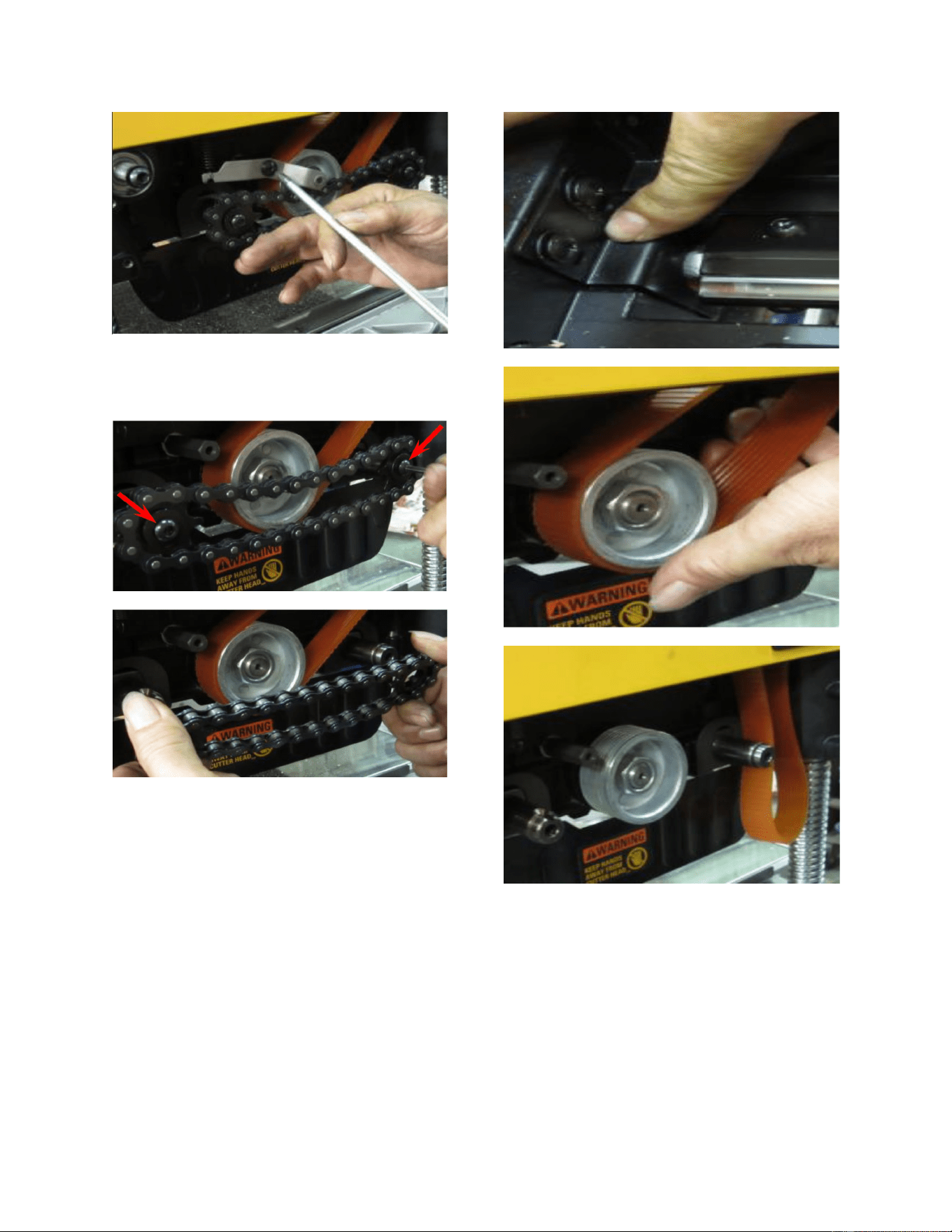
11.) Remove both the sprockets
and chain from the front and rear rollers.
12.) Press the cutterhead lock plate and
turn the cutterhead In order to remove the
belt from the pulley.
13.) Keep the cutterhead
stationary by pressing and holding the
cutterhead lock plate. Now remove the
knives alosng with the knife clamps.
6
NOTE:
Repeat the above procedure 3 times to
remove all three knives and knife clamps.
14.) Remove the cutterhead lock
plate.
15.) Release the gear box screws
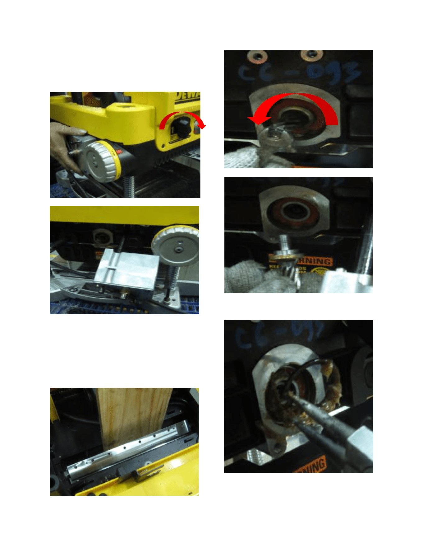
7
16.) Turn the speed adjustment
knob to the right and pull out the gear
box.
17.) Insert a board so that it is
fully wedged between the carriage and
cutterhead. No you may remove the
pinion gear by turning it counter
clockwise.
18.) Remove the R ring.
8
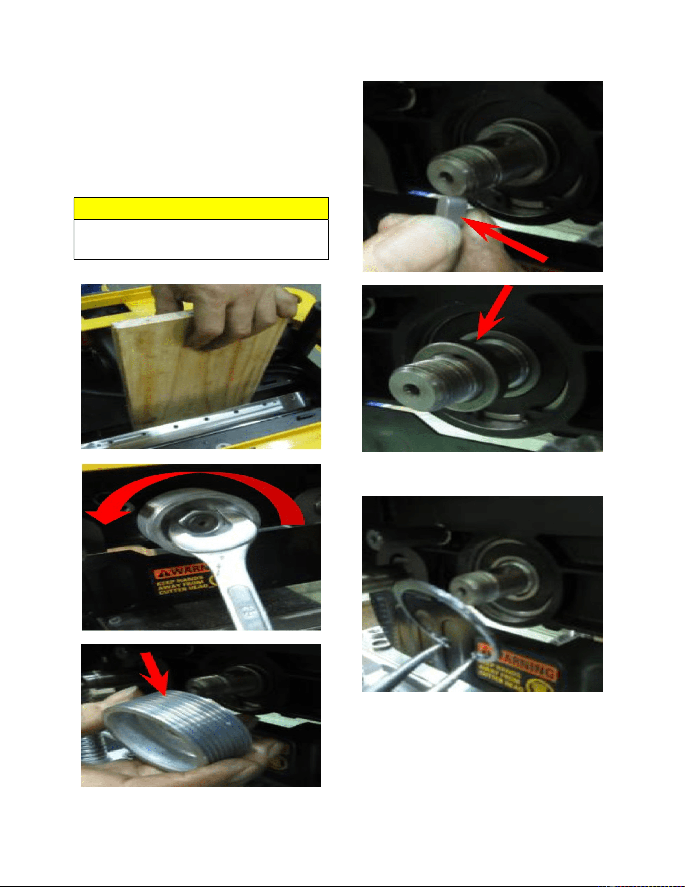
19.) Keep the board wedged
firmly between the carriage and
cutterhead. Now remove the pulley, key,
and spacer.
NOTE
Board must be wedged tight between
carriage and cutterhead.
20.) Remove the snap ring.
9
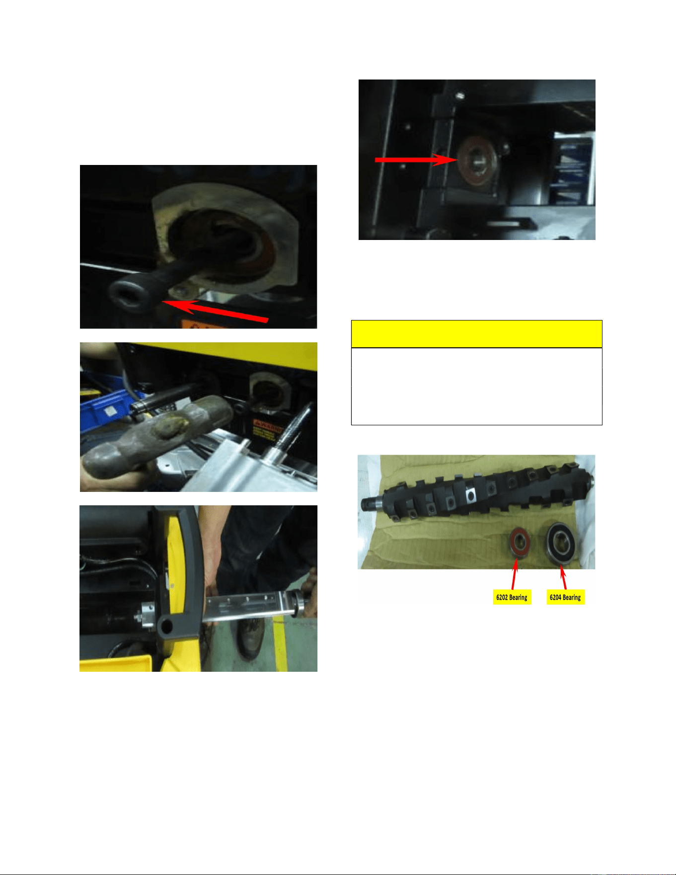
21.) Secure the cap head screw to
the cutterhead. Hammer the capo screw
and remove the cutterhead from the
carriage.
22.) Remove the bearings from
the carriage.
23.) Prepare the Spiral head and
6202 and 6204 bearings ready for
assembly.
CAUTION!!!
Wear thick leather gloves when handling
the cutterhaed to prevent accidental
contact with the sharp inserts resulting in
personal injury
24.) Put the Spiral head through
the right hole then the left hole. Now
secure a cap screw to the left threaded
hole of the Spiral head. then remove the
cap screw.
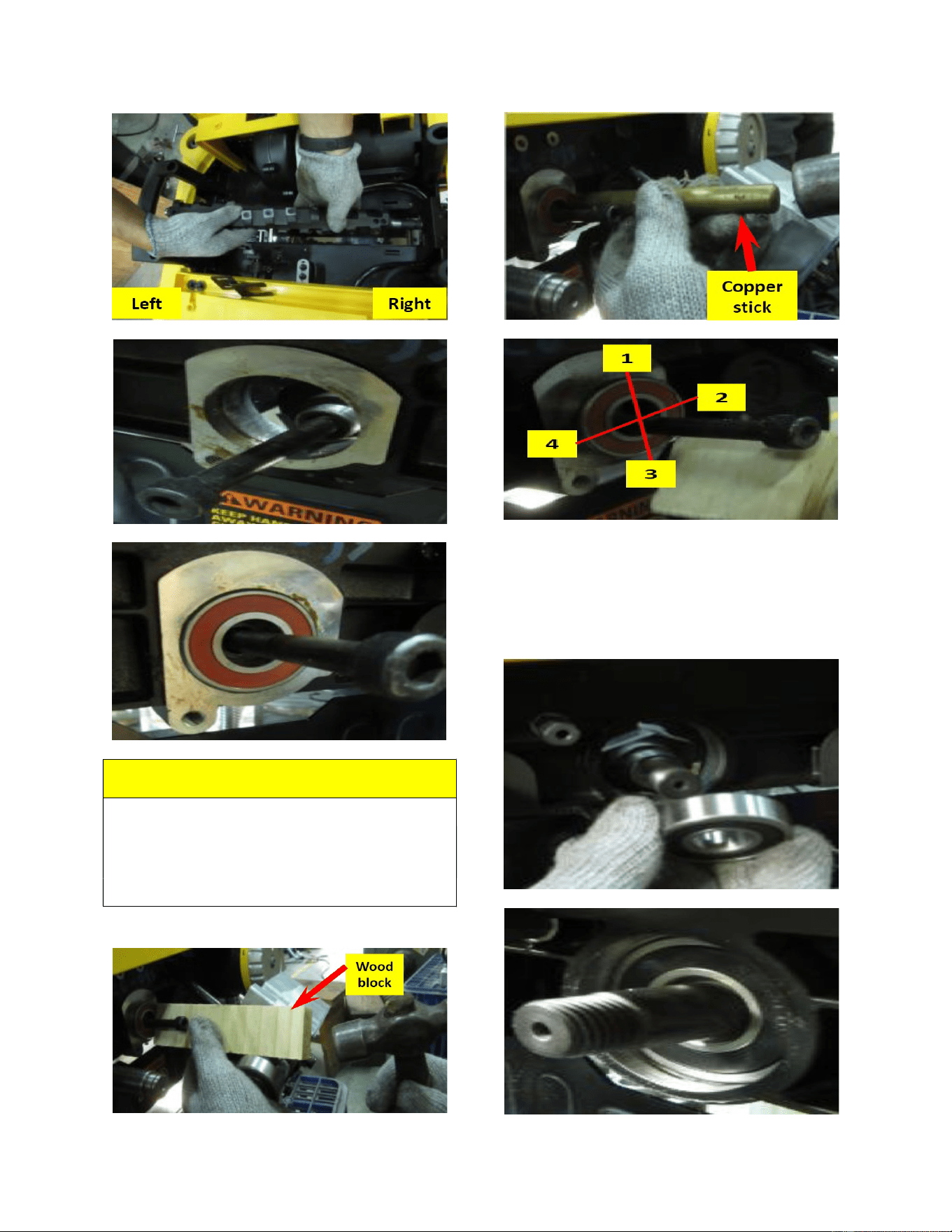
10
NOTE:
Use a wooden block or copper stick for
hammering the bearing into place. Follow
the numbered steps for hammering as
indicated below.
25.) Hammer the 6204 bearing
into the right side of the carriage until the
ring groove is exposed. Now install the
snap ring into the carriage.
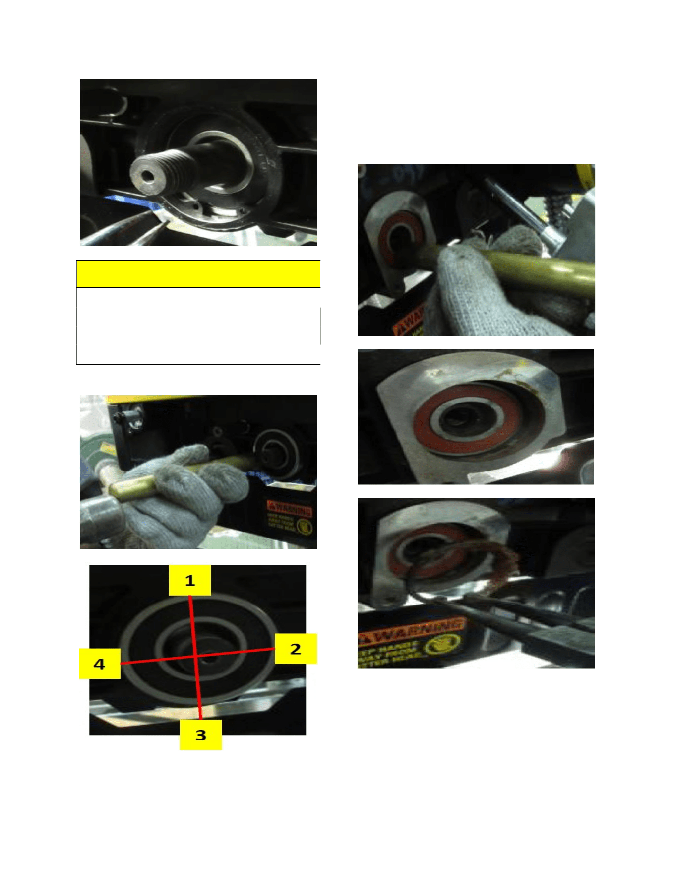
11
NOTE:
Use a wooden block or copper stick for
hammering the bearing into place. Follow
the numbered steps for hammering as
indicated below.
26.) Hammer the 6202 bearing in
to the Spiral head until the ring grove is
exposed. Now put the snap ring into the
carriage.
12
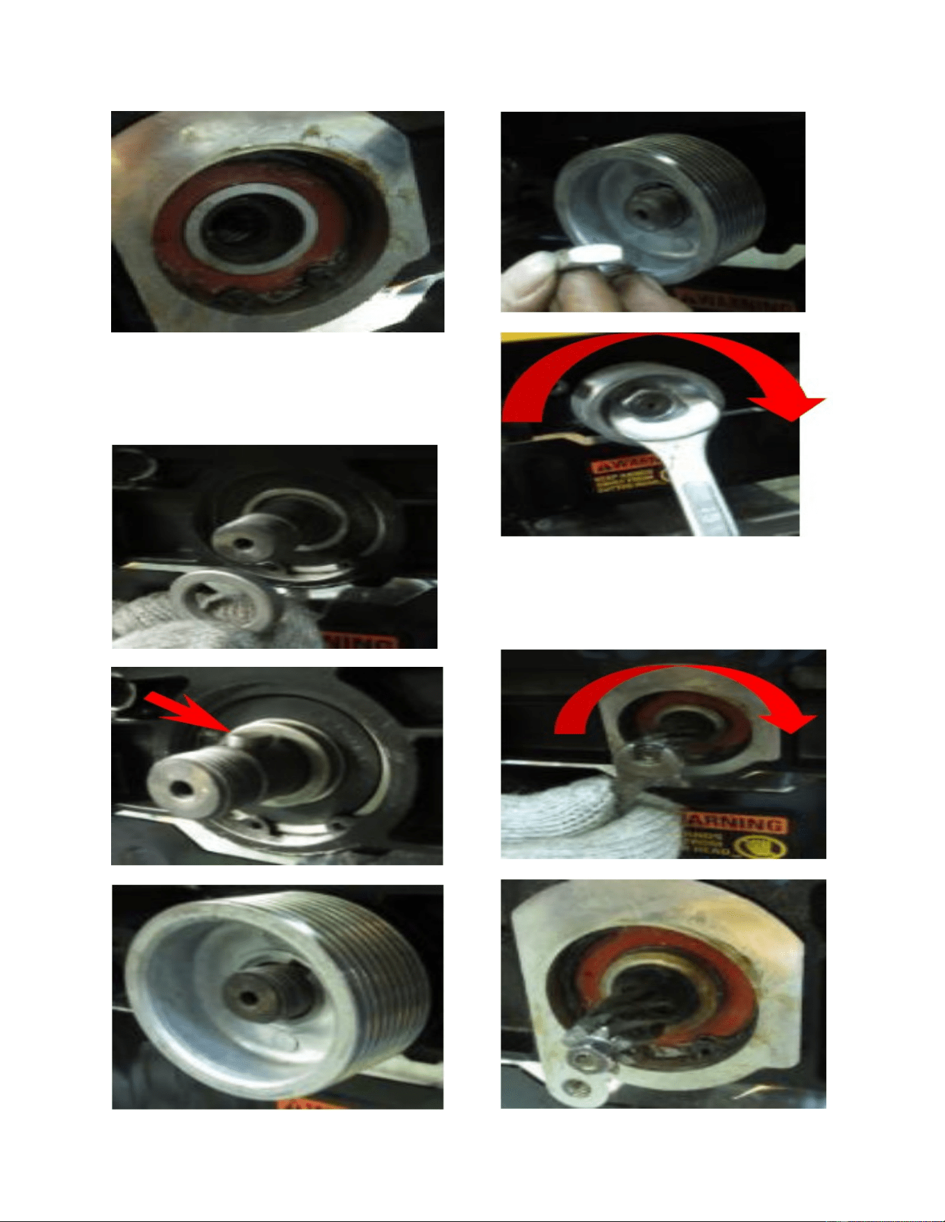
27.) Re-install the spacer, key,
and pulley onto the Spiral head and
secure it in place.
28.) Install the pinion gear in to
the left side of the Spiral head and secure
it in place.
13
NOTE:
Make sure that both the left and right snap
rings are secured in place in the ring
grooves of the carriage before securing the
pulley and pinion gear. Now insert board
and make sure that it is jammed tight
between the carriage and the Spiral head.
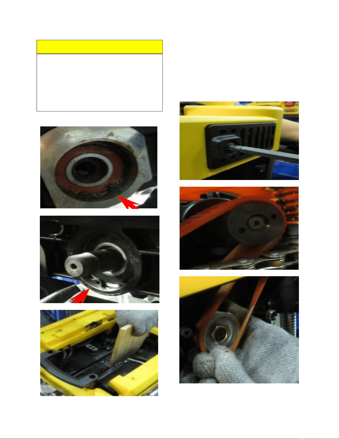
29.) Remove the belt cover to
confirm that the belt is properly seated on
the motor pulley, then put the belt on the
pulley attached to the Spiral head and
make sure that the belt is positioned
properly. Now re-install the belt cover.
14
30.) Put the shaft of the gear box
into the carriage hole and rotate the
Spiral head pulley to make sure the
positioning pin is guided into the correct
position.
31.) Turn the speed knob to make
sure the gear box shaft can go through
the carriage U shaped hole. Check speed
change knob function after assembly.
NOTE:
The locating pin on the gear box needs to
be aligned and secured at the carriage.
15
32.) Secure the gear box to the
carriage.
33.) Re-install the spacer on the
gear box shaft, then put the sprocket and
chain on both the front and rear roller
shafts. Now put the snap rings into the
rear and front roller ring grooves.
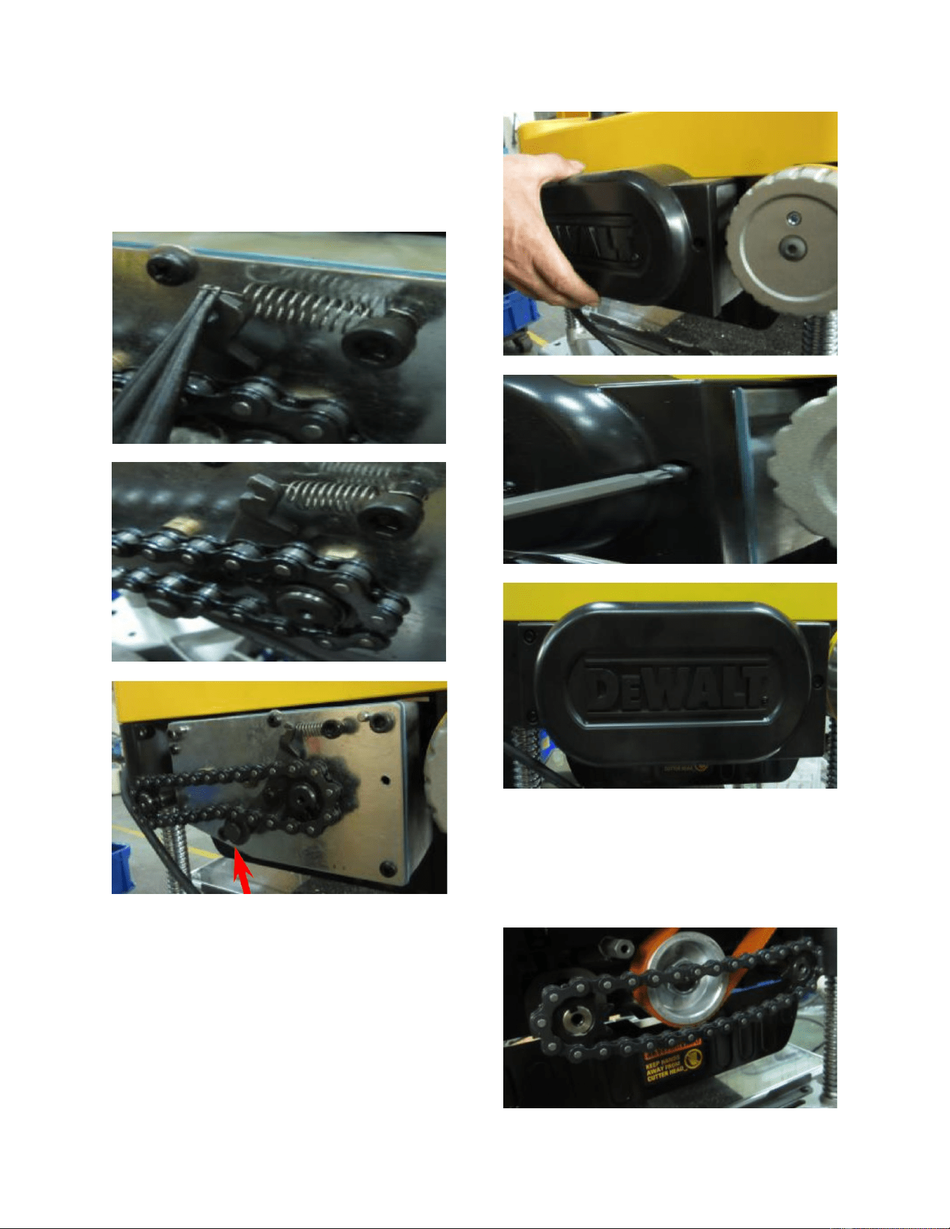
16
34.) Pull and engage the spring in
order to tension the wheel assembly
groove and make sure that the idler is
engaged along with the chain.
35.) Now secure the left side
panel to the carriage.
36.) Put the sprocket and chain
on the roller shaft located on the left side
of the machine and secure the screws on
the front and rear rollers.
17
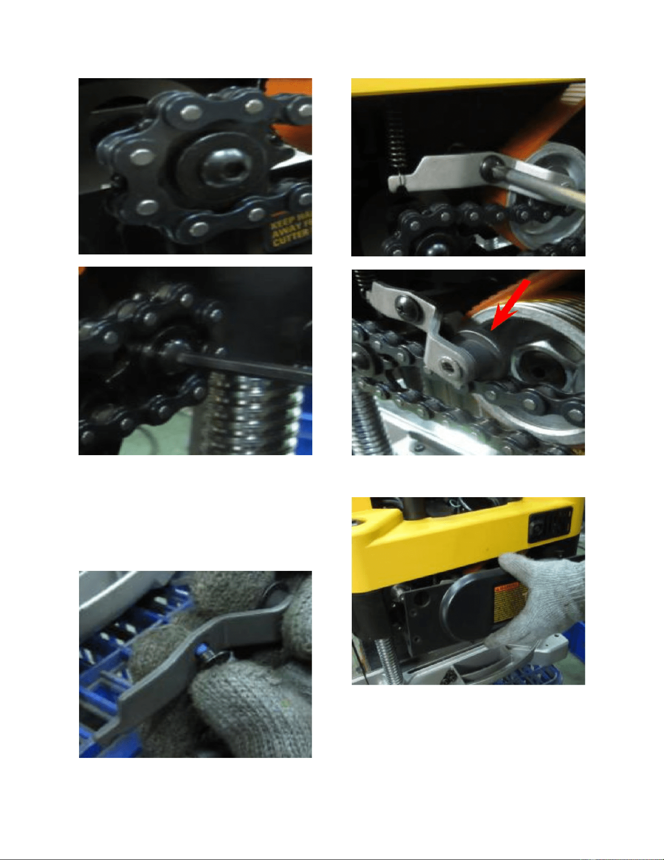
37.) Install the shoulder screw to
the tension wheel assembly and engage
the spring to tension wheel assembly.
Secure the shoulder screw and make sure
the idler is engaged along with the chain.
38.) Secure the right side panel.
18
39.) Re-install the dust port back
on to the machine carriage. Please note
the “open” text orientation for the proper
fit.
40.) Secure the dust port with the
red thumb screws and re-install the top
cover.
41.) Re-install the hand crank
wheel. Once completed turn the machine
on and test it.
19
NOTE:
FOXBC Tools is not responsible for any
damage caused by improper installation of
the cutterhead. Please check with
manufacturer of your planer before
installing as it may void your warranty.

20
Proof of purchase is necessary
FOXBC warrants every product to be free from defects in materials and agrees to correct such defects
where applicable. This warranty covers one year for parts and 90 days for labour (unless specified
otherwise), to the original purchaser from the date of purchase but does not apply to malfunctions
arising directly or indirectly from misuse, abuse, improper installation or assembly, negligence,
WARRANTY
accidents, repairs or alterations or lack of maintenance.
.
This warranty shall not apply to consumable products such as blades, bits, belts, cutters, chisels,
All warranty claims are subject to inspection of such products or part thereof and FOXBC reserves the
right to inspect any returned item before a refund or replacement may be issued.
punches etceteras.
FOXBC shall in no event be liable for injuries, accidental or otherwise, death to persons or damage to
property or for incidental contingent, special or consequential damages arising from the use of our
products.
RETURNS, REPAIRS AND REPLACEMENTS
To return, repair, or replace a FOXBC product, you must visit the appropriate www.foxbc.com and
contact us use email.
All returned merchandise will be subject to a minimum charge of 15% for re-stocking and handling
our prior authorization has carried out repairs to the item.
Repairs made by FOXBC are warranted for 30 days on parts and labour.
Any unforeseen repair charges will be reported to you for acceptance prior to making the repairs.
The FOXBC
be in an un-used condition and shipped in their original packaging a letter explaining your reason for
the return. Incurred shipping and handling charges are not refundable.
FOXBC will repair or replace the item at our discretion and subject to our inspection.
Repaired or replaced items will be returned to you pre-paid by our choice of carriers.
FOXBC
with the following qualifications.
Returns must be pre-authorized by us in writing.
We do not accept collect shipments.
Items returned for warranty purposes must be insured and shipped pre-paid to the nearest warehouse
reserves the right to refuse reimbursement or repairs or replacement if a third party without
Parts & Service Departments are fully equipped to do repairs on all products purchased
from us with the exception of some products that require the return to their authorized repair depots.
A FOXBC representative will provide you with the necessary information to have this done.