AUTOMATIC SMART LOCK
Installation and Setup Instructions
19
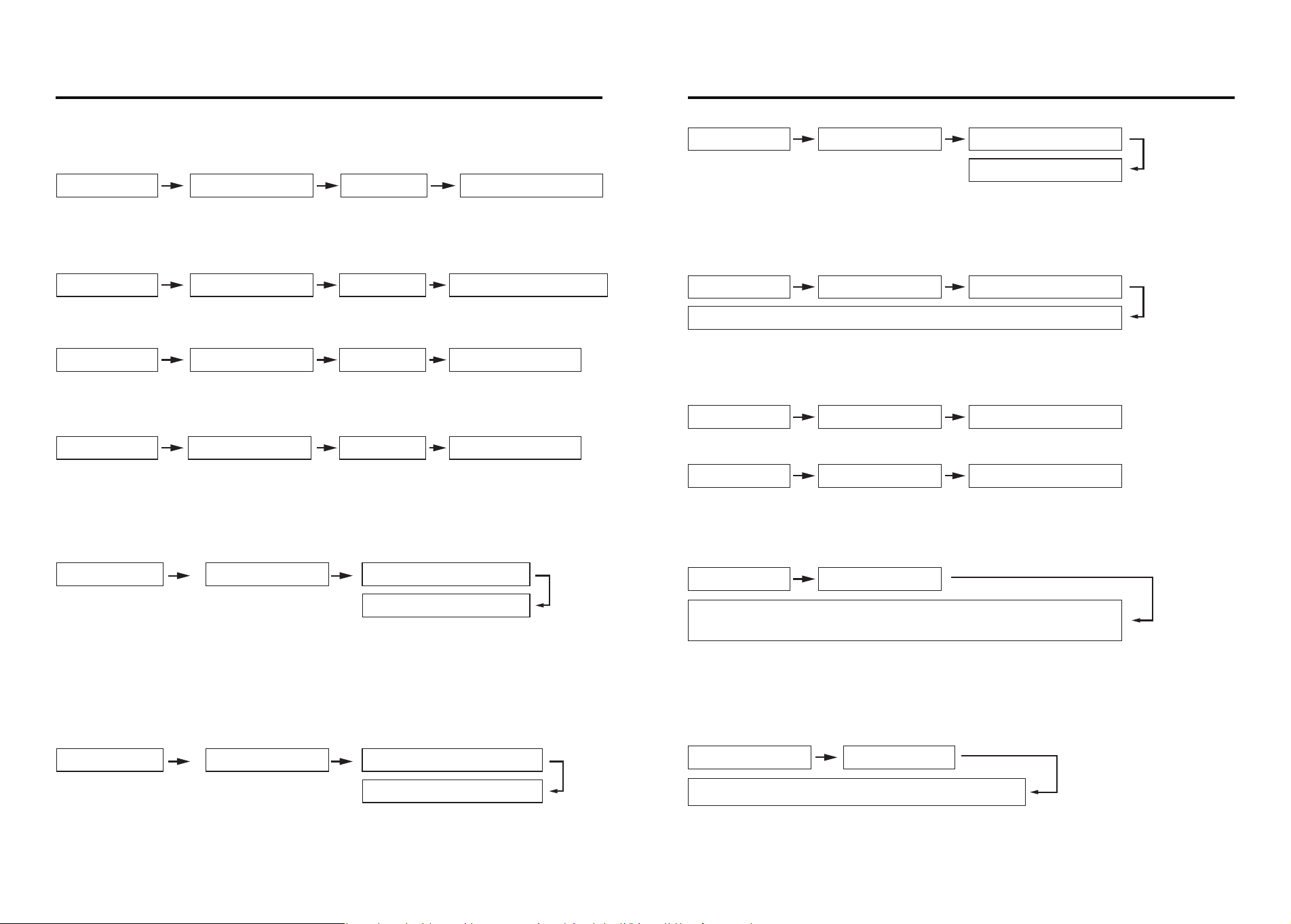
Operating menu
( 2 ) Record Query
4.Information query 2.Record query 1、Sequential search
4.Information query 2.Record query
1、Sequential search
Enter the time you want to search
(Time is month and year)
① Sequential Search
Note: Sequential query is to start with the current latest information and go down,
press key 8 to query the next one and key 2 to query the previous one.
② Search By Time
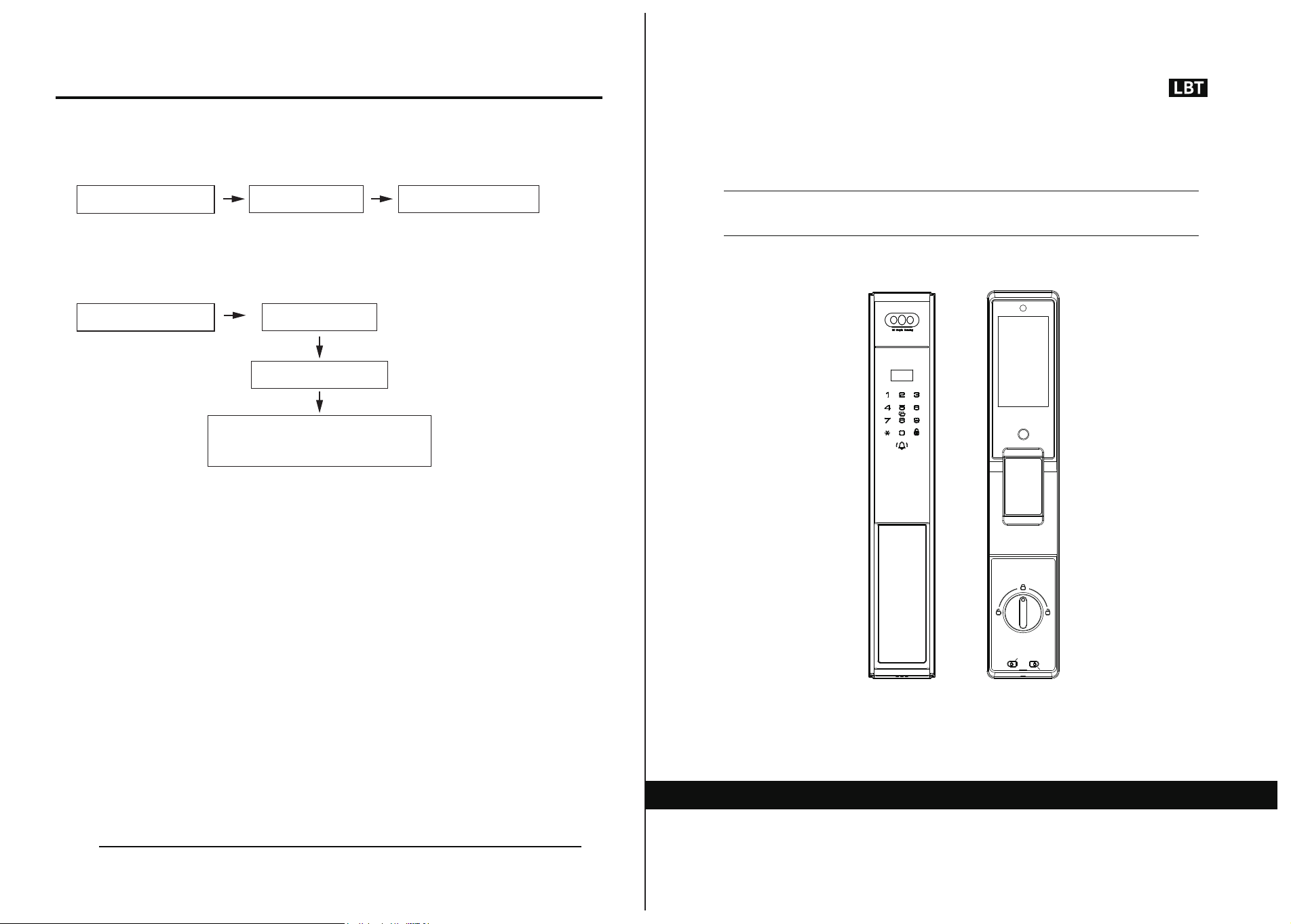
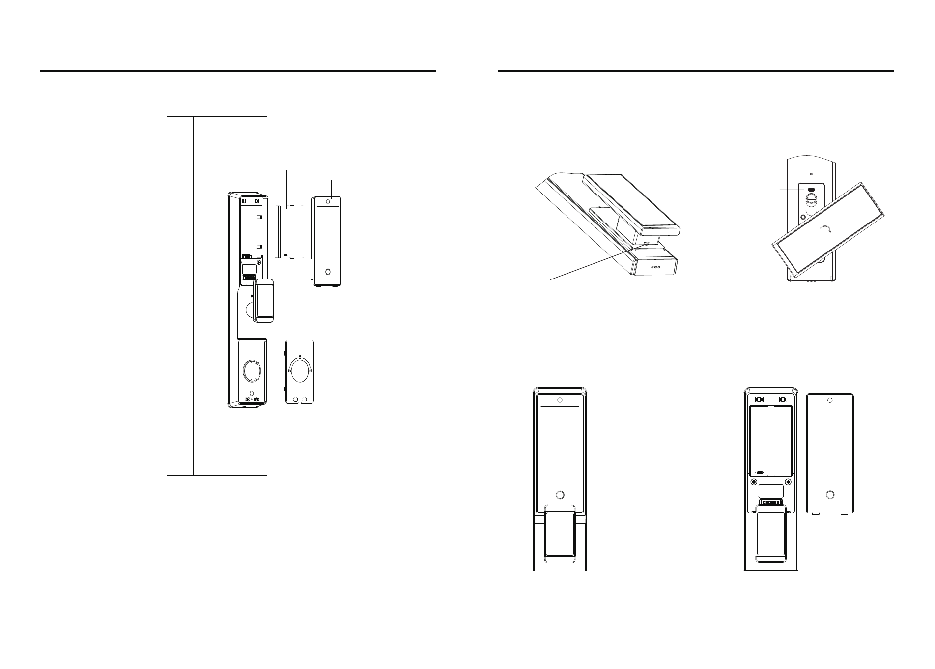
Fully automatic anti-theft lock - Tuya Wifi
P70
01 02
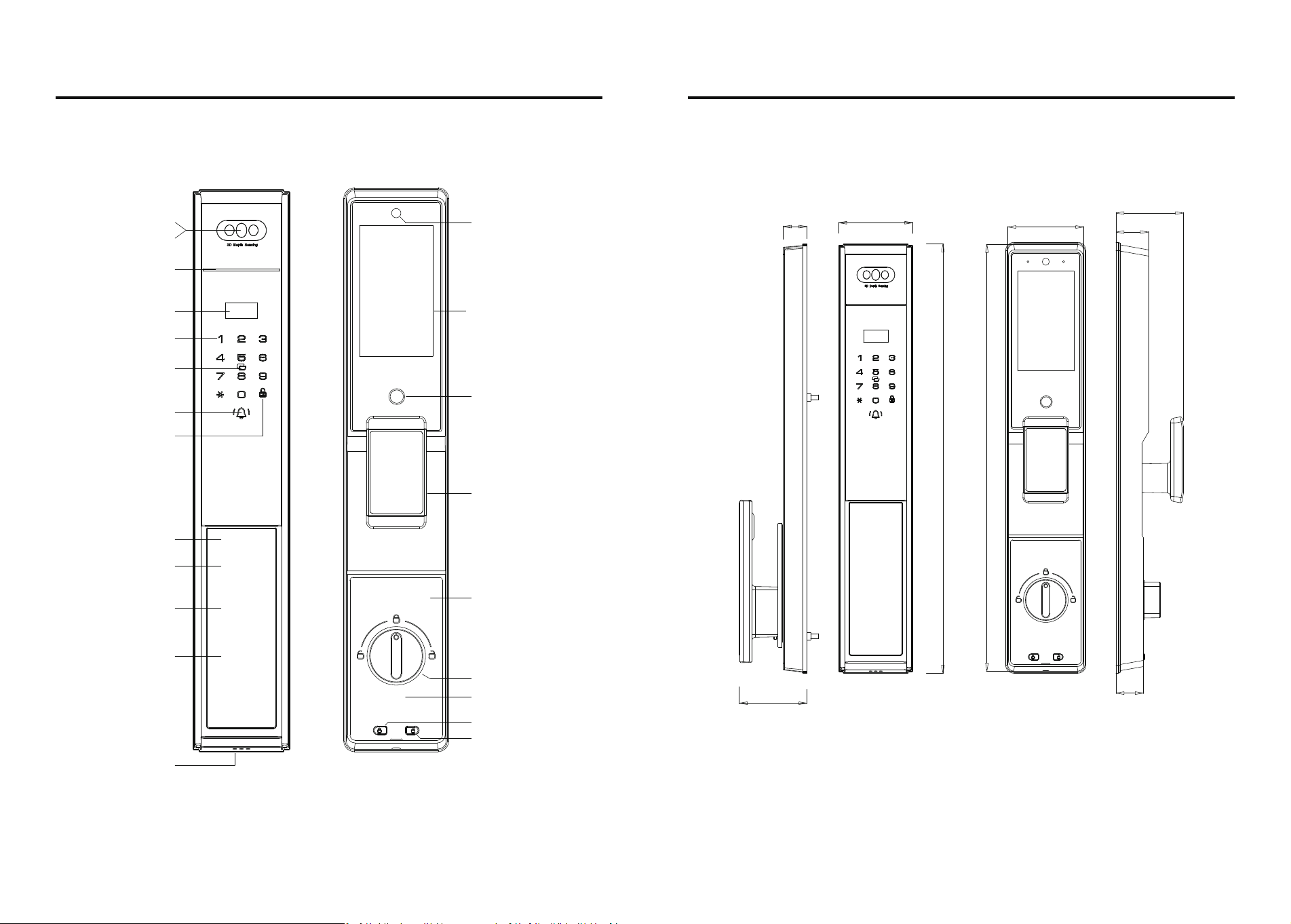
Parameters Size (mm)
Camera
Facial
Display Screen
Code
Card
Doorbell
Locked key
Indicator light
Cylinder cover
(Cylinder+Type-C)
Front handle
Unlocking Button
Locked Button
Camera display
Camera touch button
Handle
Anti-lock knob
Rear panel component
Camera lens
Decorative cover
Fingerprint
(Concealed)
Hole
Speaker hole
70
23
75
32
420
27
67
67
423
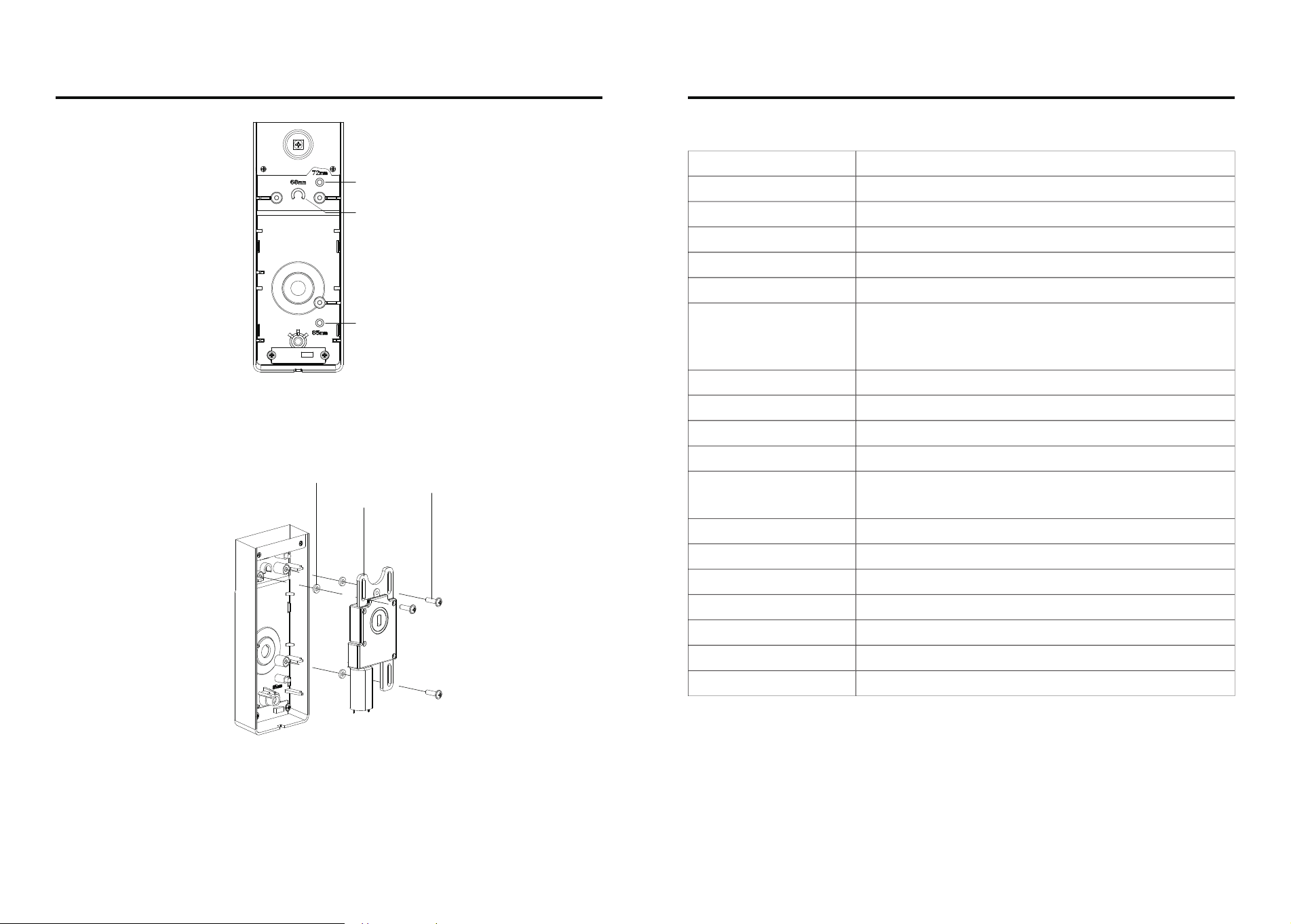
03
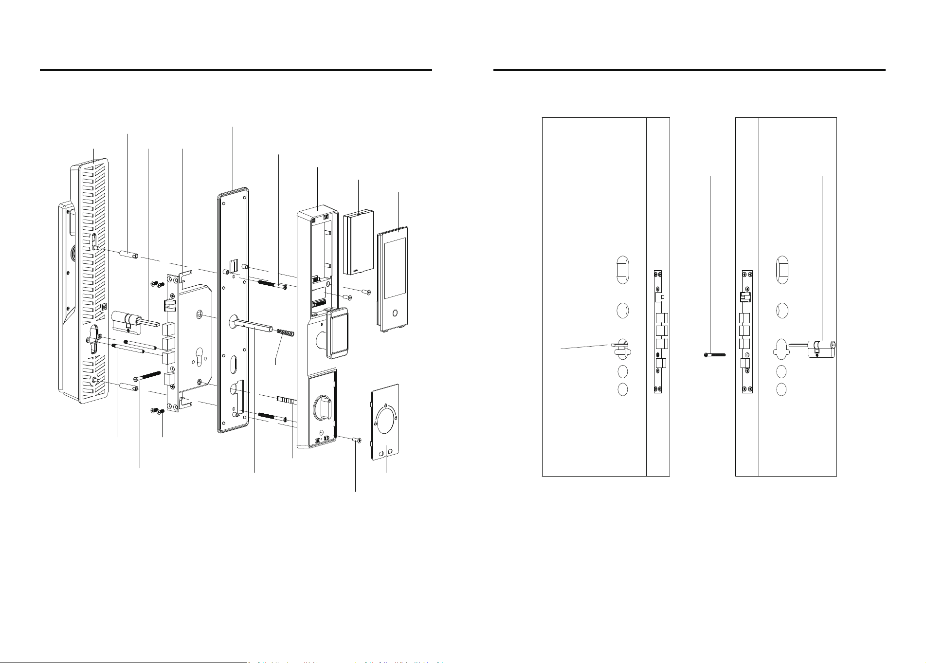
Door lock installation Cylinder installation
Front panel
Tapping stud
Rear Base Plate + Silicone Pad
Panel positioning screw
Lithium battery
Camera screen
Tapping screw
Rear panel
Mortise
Decorative cover
Knob tail
Cylinder positioning screw
Spindle
Spindle
spring
Cylinder
Mortise positioning stud
Length of lock cylinder tail
protruding from
door panel: 18-21mm
Cylinder
Cylinder screw
Cable hole
Spindle hole
Cable hole
Spindle hole
1.1 Installation of the cylinder: install the lock cylinder to the position as shown in the picture, use
a M5 screw to fix the cylinder, check the length of the tail shaft of the cylinder, the length of the
protruding door plate: 18-21mm, need to cut off the excess part.
Screw
04
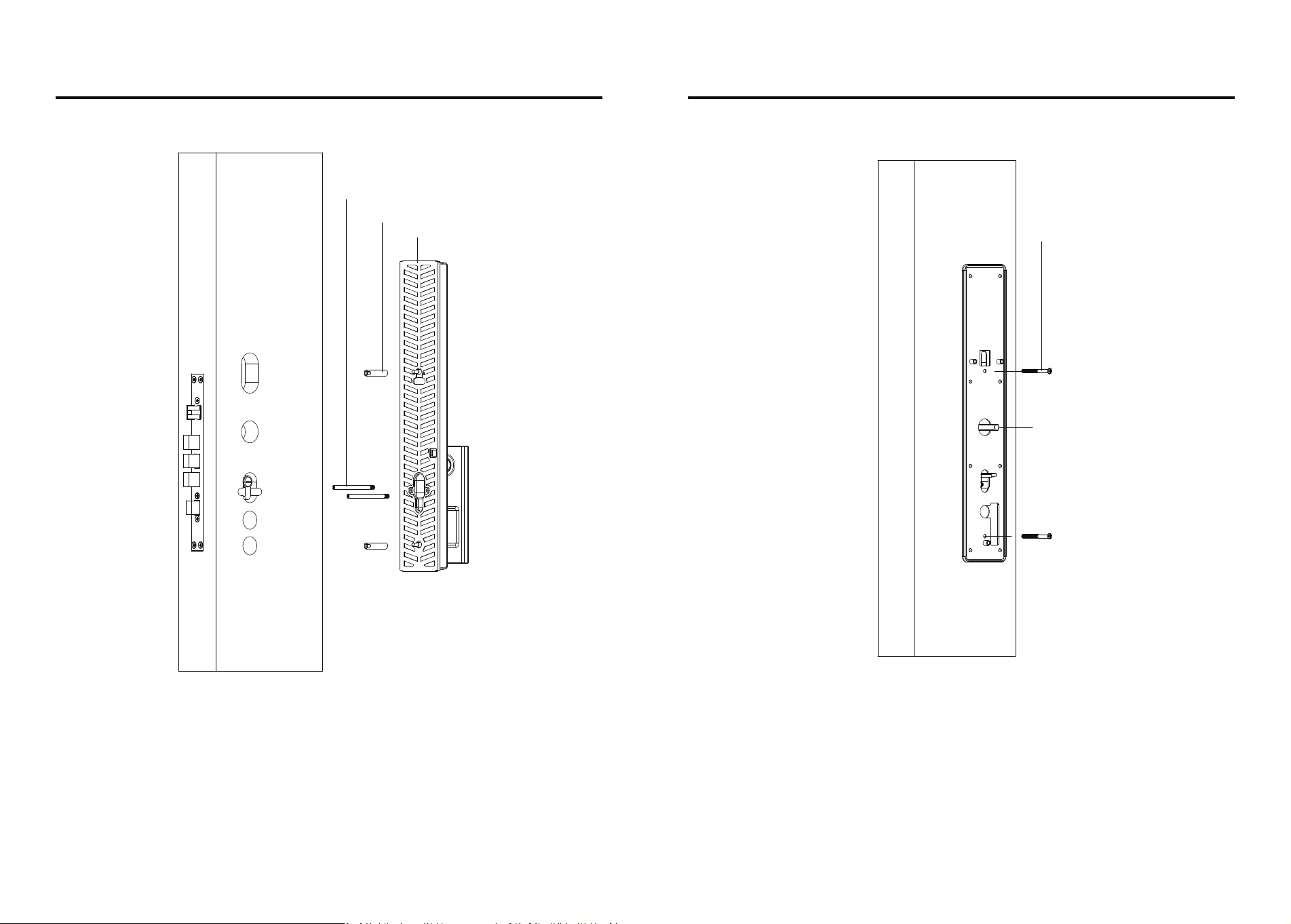
1.2.1 Screw the Tapping stud and positioning stud to the front panel, and then lead the connect-
ing wires of the front panel and the camera through the door panel to the indoor direction, align
the position of the lock cylinder, and install it into the front panel.
1.2.2 first load the spindle suitable for the door thickness (hit point near the end of the door
towards the outside), the front panel is adjusted, with two M5 screws through the rear plate to fix
the front panel, before tightening the screws, be sure to adjust the spindle and the cylinder to the
center of the corresponding round hole in the rear plate position.
05
Front panel installation-1 Front panel installation-2
Screw
Spindle
06
Front panel
Tapping stud
Positioning stud
Cable hole
Spindle hole
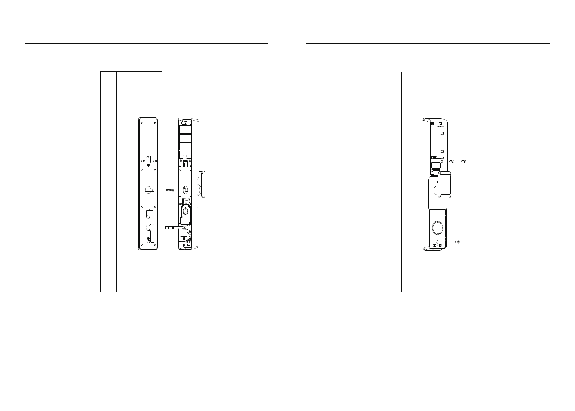
1.3.2 Fix the rear panel with three M5 screws, rotate the rear handle and anti-lock knob to see if it
rotates smoothly (if it does not rotate smoothly, please refer to 1.2 Installation Steps to adjust the
rear bottom plate so that the spindle and the cylinder are in the center of the rear bottom plate
hole).
1.3.1 First, cut the cylinder tail to the appropriate length according to the door thickness, insert
the connectors of the front panel and the camera with the corresponding connectors of the rear
panel, load the spindle spring (big end facing inward), align the holes, and load the rear panel.
07
Rear panel installation-1 Rear panel installation-2
Spindle spring
Panel positioning screw
08
1.3.3 load the lithium battery, cover the battery cover and decorative cover, test whether the
mechanical key can open and close the lock normally, test whether the door lock can be used
normally. (The factory lock defaults to the left, if the direction is not right, please refer to the
manual to set the locking direction)
09
Rear panel installation-3 Appendix 1-2
Lithium battery
Camera screen
Decorative cover
10
Attachment-1: Emergency spare key and emergency charging method (as shown above)
If there is an emergency situation such as forgetting the password, running out of battery
power or abnormal circuitry that prevents you from unlocking the door, you can use the
emergency spare key to unlock the door or use the rechargeable battery for emergency power
supply to unlock the door.
1. Press and hold this button with your thumb downward.
2. Turn the handle to the left/right about 60 degrees
3. Return the handle to the right after use.
Attachment-2: Battery cover removal and mounting operation
Attention: Since there is an electronic part of the cat's eye module inside the battery cover,
be careful to prevent the battery cover from falling off during operation.
Emergency power port
Cylinder hole
60°
1. Press the two holes of the
battery cover at the same time
to make the top end of the
battery cover pop up;
2. After the battery cover pops
up, remove the battery in an
upward direction.
Attachment-3.2
Unscrew the fixing screws, remove the geared motor, put the motor back in alignment with the
corresponding positioning marks, and tighten the fixing screws; Note: Make sure that the damping
pads do not fall off during operation.
Note: Ensure that the damping pads do not fall off during operation.
72 mortise position
68 mortise position
85 mortise position
Vibration dampener
Motor
Screw
Attachment-3.1
The panel is engraved with the corresponding positioning mark of each lock body,
installation attention to distinguish;
11 12
Appendix 3 (switching installation operation of locks 68, 72, 85) Parameters
Fingerprint
Capture head resolution
Rejection rate
False recognition rate
Fingerprint collection range
Card type
User capacities
Operating record
Battery life
Operating voltage
Static power consumption
Recognition time
Keypad type
OLED display
External emergency power
Antistatic capability
Storage temperature
Operating temperature
Environmental humidity
Self-learning capacitive fingerprint head
508dpi
<0.1%
<0.001%
±180°
M1
Rolling 600
Unlocking ≥3000 times
7.0V~8.4V,low voltage alarm voltage6.8±0.2V
≤200uA(Average power consumption)
≤3s,(Including the whole process of fingerprint
acquisition, comparison and unlocking signal output.)
Touch sensitive
0.96’’ LCD
5V1A Type-c
≥8KV(contact)≥15KV(contactless)
-25℃ ~ 80℃
-25℃ ~ 70℃
15%RH~ 93%RH
Total capacity 250 groups: up to 100 fingerprints,
up to 100 passwords, up to 50 faces, up to 100 cards.
Administrator ID range 000-009,
general user ID range 010-249
功能与操作
13 14
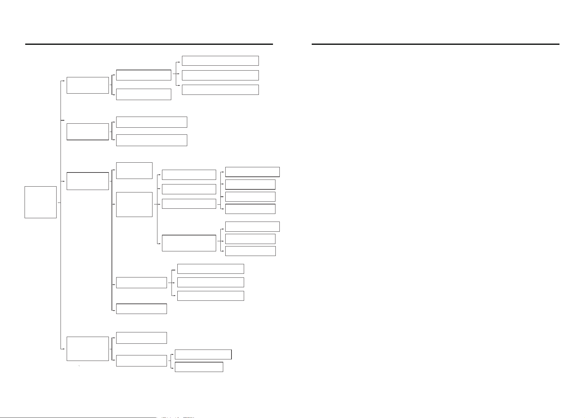
Operating Menu Setting Description
1.
Add user
1.Add admin user
2.Add general user
1.Add fingerprint,card,code
2.Add face
3.Add palm
1.Sequential search
2.Search by time
1.Opening direction
2.Delayed locking
3.Lock setting
4.Face Recognition
Settings
1.Anti-prying alarm
2.Motor torque
3.Lockback time
1.Human interaction
2.Sensing distance
3.Recognition tips
4.Staying alarm
2.
Delete user
1.Network configuration
2.Lock volume
3.Dual verification
1.Verify deleted users
2.Delete users by number
4.
Information
query
1.Number of users
2.Record query
3.
System setting
Press *# to
verify
admin
information
1.
Time setting
2.
Installation
setting
3.Function setting
4.Initialize system
1.Initialization
Press and hold the setup button for 5s, voice announcement: “Restore factory settings, to
confirm, please press the # key, to cancel, please press the * key”, press the # key to confirm, the
system will restart to the initial state.
Under the initial state, any face, fingerprint, password or card can unlock the door. The factory
setting operation cannot clear the set parameters of door opening direction and torque.
2. Low battery alert
System power is less than 25%, when unlocking the voice announcement: “low battery”, the
battery can still unlock about 50 times, but please charge in time (or replace the battery).
3. External USB emergency power supply
Using USB emergency power supply, it takes about 30 seconds to unlock the door.
4. Illegal User Alarm
When the lock fails to be unlocked for 3 to 5 consecutive times, the voice will announce: “Illegal
user, illegal invasion, the owner has been notified”. The system will be locked for 90 seconds
after the 5th announcement, and will not respond to any operation by the user during this
period, and will be unlocked after 90 seconds.
5 . Dummy Code
When using password to unlock the door, you can add any number before or after the correct
password, which can increase the security of the numeric password, such as the password is
“123456”, you can enter “426123456745” to unlock the door.
Note: The system can only recognize the first 16 digits.
6. Version Number
Input 999# to read the system version number.
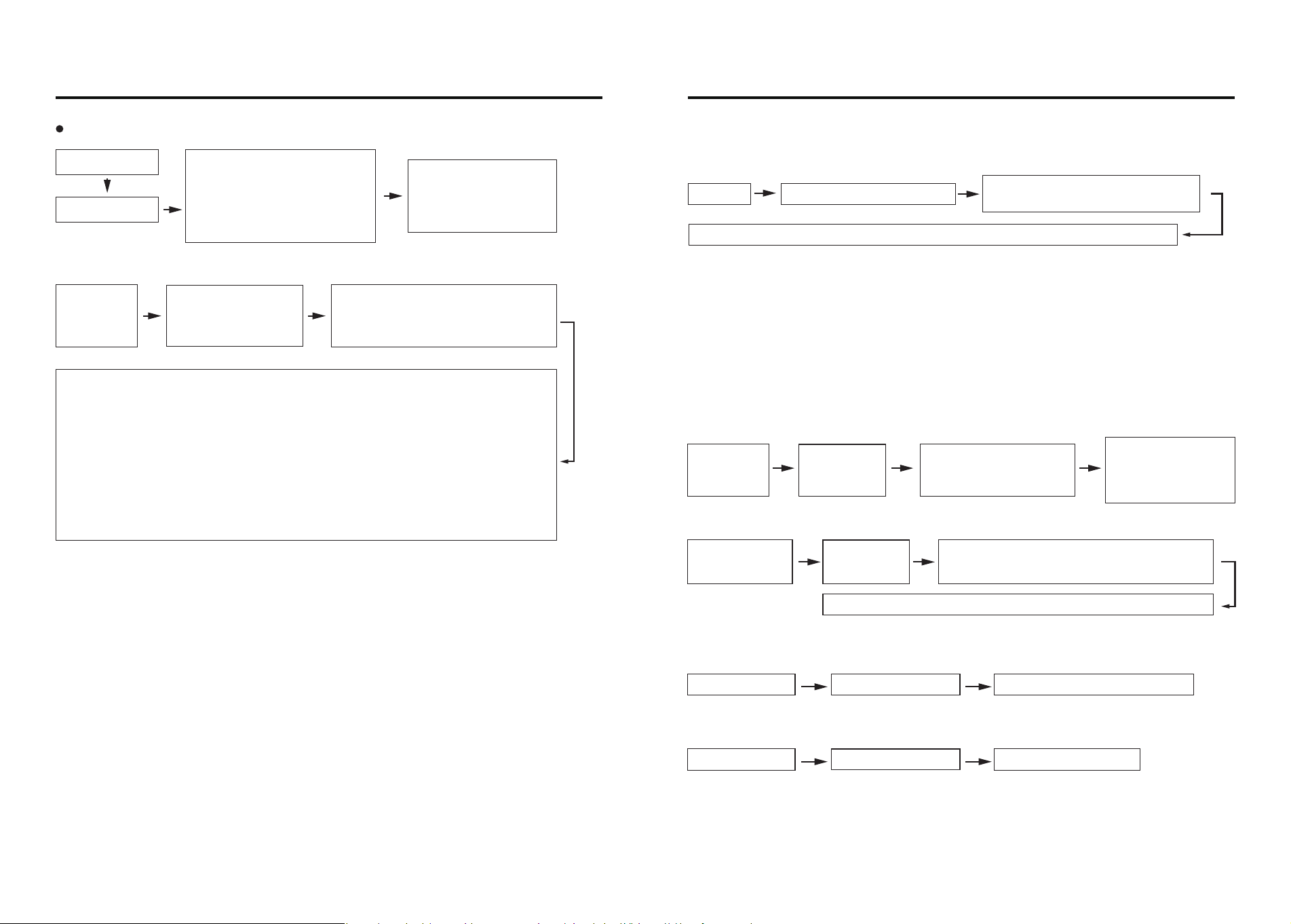
Adding an administrator password for the first time
1.Add User
2.Delete User
(1)Verify the deletion of the user
Touch the lock
1.Add user
1.Add admin user
2.2.Add general user
Press*+#key
1.Add fingerprint,password,card
2.Add face
3.Add palm
2.Delete
Verify the deletion of the user
功能与操作
15 16
Function And Operating Setting description
Face: Voice announcement “Please input the face”, the face to be recorded parallel to the camera at
a distance of 30~80cm, according to the voice instructions for continuous recording.
Fingerprint: users place their fingers on the fingerprint sensor, the voice prompts “please press
your finger again”, users will place the same finger on the sensor, continuous recording.
Password: User inputs 6 to 8 digits password and presses # key to confirm.
Card: User puts the card close to the IC card sensing area of the touch keypad, the system automati-
cally reads and saves the card information.
Palm vein: voice announcement “please input the face or palm vein”, the hand to be recorded
parallel to the camera at a distance of 25-35cm, according to the voice prompts for continuous entry.
Note: The number of administrative users: No. 000-009, total 10 digits; the number of general users:
No. 010-249, total 240 digits.
Verification method:
Face: the user's front face parallel to the camera at a distance of 30-80cm Fingerprint: the finger to
be deleted is placed on the fingerprint sensor. Password: Enter the password to be deleted.
Card: Place the IC card to be deleted close to the sensing area of the touch panel.
Palm Vein: Place the palm to be deleted parallel to the camera at a distance of 25-35cm.
If the user exists in the system, voice announcement: “Delete Success”; if the user does not exist,
voice announcement: “Operation Failed”.
Voice Announcement:
“To add an administrative user,
please enter a 6- to 8-digit
password and press # to
confirm” (enter password)
After successful addition,
voice announcement:
“User
Press the number “1”
Please enter the password, fingerprint or card you want to add, user ***, added
successfully. Press “2”.
Please enter your face, please raise your head slightly, please lower your head slightly,
please turn your face to the right hand side, please turn your face to the left hand side,
user ***,add successfully.
Press the number “3”
Voice announcement: Please place your palm in front of the camera, the display will
show: Please enter palm vein user ***, added successfully.
Voice over:
“Please verify the user to be deleted”
After successful authentication, the voice announces, “User ***, deleted successfully.”
①Time Setting
3.System setting
1.Time setting
Voice announcement: “Please enter the time.”
(Enter the time in the following format: _- _- )
After successful setup, the voice announces, “Operation successful.”
② Installation Settings
a. Opening direction setting
Note: The direction of opening the door is based on the direction of unlocking outside the door.
Delayed Locking:
After unlocking, the door lock automatically performs locking operation within the specified time.
User settable: 10S, 15S, 20S, 30S, 60S, 120S.
3 . System setting 2 . Installation setting
1. Direction of opening [left open]
3.System setting 2 . Installation setting
2. Delayed locking [OFF]
b. Delayed locking
(2)Delete users by number
2.Delete user
2.Delete users
by number
Voice over: “Enter the user
number to be deleted.”
After successful
deletion, the voice
announces, “User ***,
deleted successfully.”
Note: After turning on the anti-picking alarm, if the door lock is picked, the system will send out an
alarm prompt: “Illegal user, illegal invasion, the owner has been notified”. If the device has been
networked, it will push the alarm information to the cell phone.
Note: Dual verification is only for normal key unlocking, two different normal user keys have to be
verified to unlock the door successfully, the administrator user can unlock the door directly.
Note: After restoring the factory settings, the user data will be completely emptied, users should be
careful.
Note: Within 1 minute, the human body is detected for a total of 20 seconds, which will trigger the
stay alarm and push to the distributed equipment, and the local sound and light alarm is not
carried out by default.
Notes:
1. Human body sensing function classification:
-Body Sensing [Off]:The door lock does not perform body sensing.
-Body Sensor [Smart]:The door lock performs body sensing only in the closed state.
-Body Sensing [Open]:The door lock performs body sensing in any state.
2. 10 consecutive wake-ups and no face is recognized, the human body sensing is turned off by
default for 5 minutes.
功能与操作
17 18
Function and operating Setting description
4.Information query
(1)Number of users
c. Lock Setting
· Anti-prying alarm
3.System setting 2.Installation setting 3.Lock setting 1.Anti-prying alarm OFF
3.System setting 2.Installation setting 3.Lock setting 2.Torque setting 【Medium】
3.System setting
2.Installation setting 4 .Face Recognition Setting
Human interaction【ON】
3.System setting 2.Installation setting 3.Lock setting 3.Lockback time【2s】
3.System setting 2.Installation setting 3.Lock setting 4.Staying alarm【20s】
3.System setting 2.Installation setting 4.Face Recognition Setting
3.Recognition tips【ON】
d. Face Recognition Setting
· Human interaction
· Motor torque
Note: Torque setting is for motor torque strength.
· Lockback time
Note: The lock time is the rebound time of the lock tilt tongue,
and the set time range is between 2s and 9s.
· Staying alarm
· Sensing distance
Note: Sensing distance 【near】: 30~50cm;
Sensing distance 【middle】: 50~70cm; Sensing distance 【far】: 70~80cm.
· Recognition tips
Note : Turn on the recognition prompt, when the human body sensor wakes up,
the voice prompt: “Please record the positive face”.
(3)Function Setting
①Network conguration
Note: After restoring the factory settings, the user data will be completely emptied,
users should be careful.
② Lock volume
③ Dual verication
(4) Initialize system
3.System setting 3.Function setting 1.Network configuration
After successful networking, voice announcement: “Operation successful”
Confirm the restoration of factory settings,
voice announcement: “Empty successfully”, the system reboot
3.System setting 3.Function setting 2.Lock volume【High】
3.System setting 3.Function setting 3、Dual verification【OFF】
3.System setting 4、Initialize system
Voice announcement: “Admin user ***, general user ***”
4.Information query 1.Number of users
3.System setting
2.Installation setting 4 .Face Recognition Setting
2. Sensing distance 【Medium】

Tuya App Instructions
Installation and setting instruction
SLIM SMART DOOR LOCK
Add administrator to door locks
Equipment addition process
1
2
Equipment addition process
2
① light up the door lock screen, click on the touchpad [*] + [#], enter the
verification administrator, the administrator password default is [123456],
click on the [#] sign to confirm, (different models of door locks, the initial
administrator password may differ);
② Select [Administrator Settings], [Enter Administrator], select the admin-
istrator number to be entered, and click [#] to confirm;
③ Enter the 6~15-digit administrator password and click the [#] sign to
confirm. Enter it again and confirm by clicking on the [#] sign;
④ Wait for the display to go down or click the [*] sign continuously
to exit the setting;
⑤ Other door lock users are set up as normal door locks.
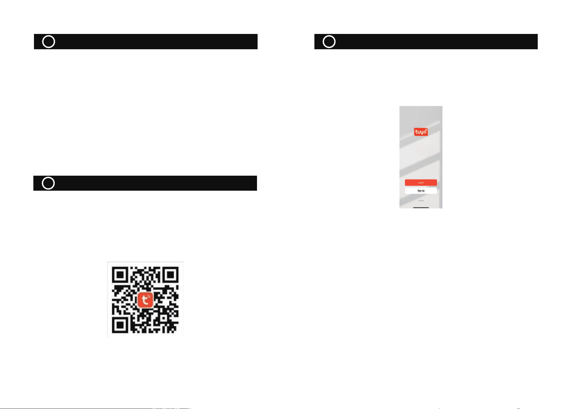
2.1 APP DOWNLOAD
Search "Tuya Smart" in various application markets or scan the QR code
below to download.
2.2 Sign Up/ Login/ Forgot Password
After downloading and installing the app, you can register if you don't have
an account, and you can choose the login screen to log in if you have an
account, and you can reset your password by retrieving it if you forget it.
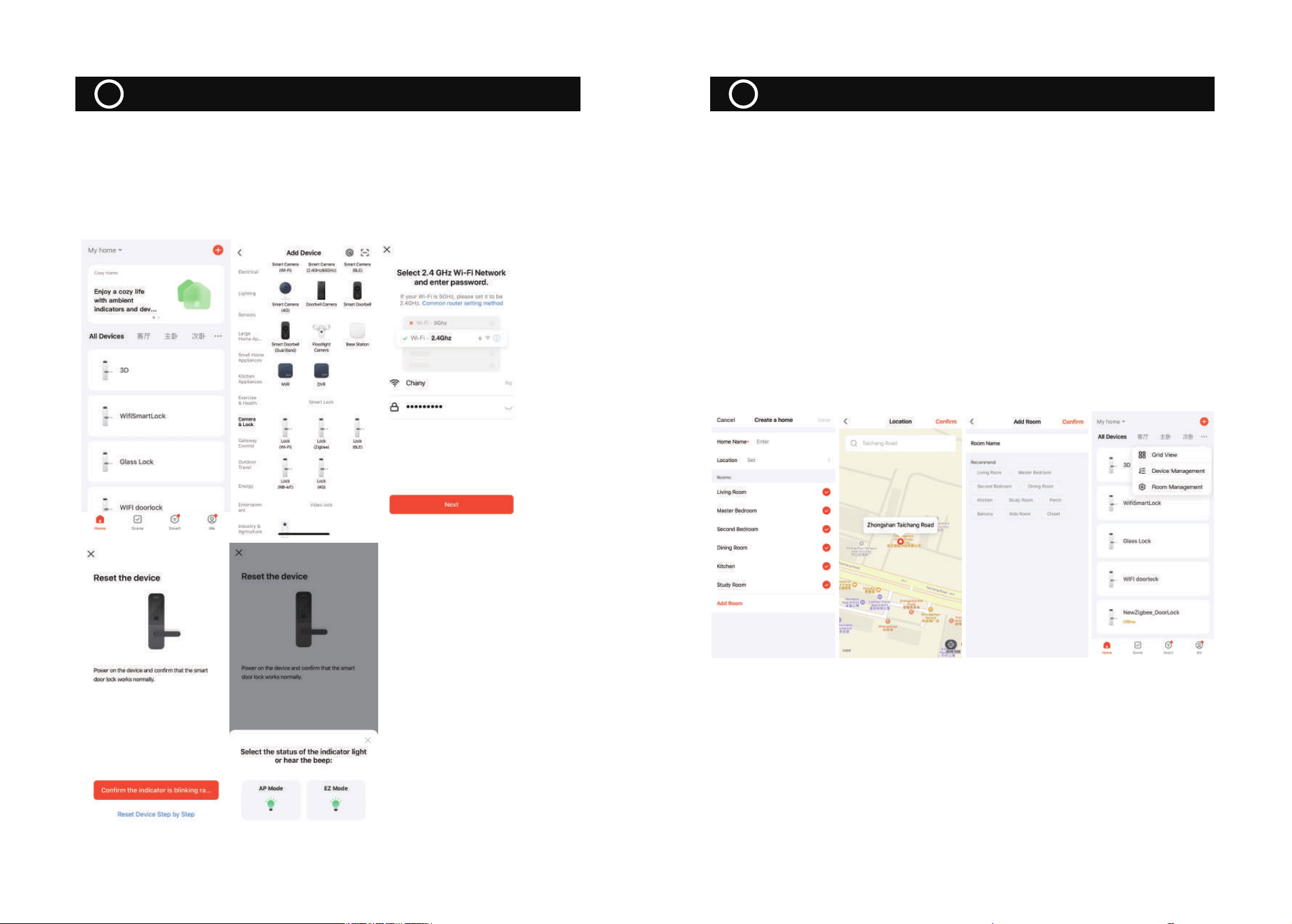
2.3 Add Tuya WIFI Lock
① To ensure that the door lock has added an administrator user before you
can add the Tuya WIFI lock, please see“Add administrator to door locks”;
② When you are ready to add devices, click "Add Device" or "+" at the top
right of the app to enter the "Add Device" page;
③Click on "Camera& Lock" and find "Lock (Wi-Fi)" to access it;
④ Select 2.4GHz Wi-Fi network and enter the password into the next step, if
you do not open the GPS positioning, open this page will prompt the need
to open the cell phone positioning right root, go to the phone settings to
open;
⑤ Short press the setup button and wait for the Wi-Fi module indicator to
flash rapidly, i.e. enter the wiring mode;
⑥ Mobile side selection of flash (0.5/1 time) for pairing;
Equipment addition process
2
3.1Home Management
① After logging in to your account, click "Me" -> "Home Management" to
enter the "Creat a home" page, as in Figure 1; "Home Name" can be manu-
ally entered to customize it;
②Click on "Family Location" to enter the map page, you can manually
move the family coordinates to change the address, and click on "Confirm"
after the address, as in Figure 2;
③ Click "Add another room" to add room information, as shown in Figure
3, and click "Finish" in the upper right corner to complete the room
settings. You can also modify the room settings at any time by clicking the
"..." button on the page, as shown in Figure 4;
⑦ Wait for the successful addition, modify the [Device Name], click [Finish]。
Note: The matching speed varies according to the WIFI channel congestion
status, about 15~50 seconds, the matching timeout is 90 seconds, you can
observe the status of the Wi-Fi module indicator to determine if the matching
mode has been exited.
Home/ Member Management
3
WiFi door lock APP application
4
① The ability to invite targeted users into the family by adding members;
② Added members will receive a pop-up alert in the app, which you can
choose to accept or reject, and will also be alerted in the message center;
③ The family owner can set "Administrator" and "General Member" permis-
sions for the invited family members;
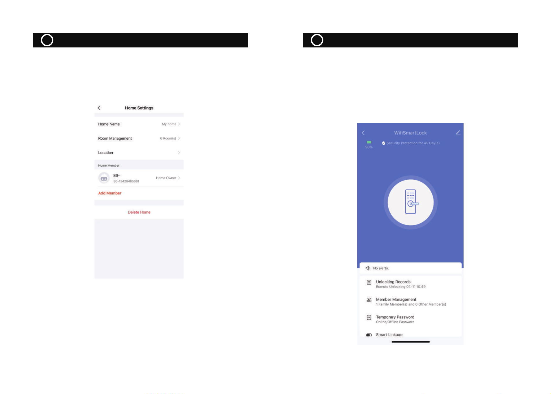
3.2Home Settings
Click Tuya App“Me”—>“Home Management”—>My home, enter the
setting interface.
The door lock APP can be used for remote unlocking, dynamic password
unlocking, member management, record query, temporary password
management, etc., as well as low pressure alarm, lock picking alarm,
continuous trial and error alarm, doorbell call and other record-based
functions. The following is a separate demonstration of the "remote
unlocking", "dynamic password unlocking" and "temporary password
unlocking" functions that are prone to problems.
Home/ Member Management
3
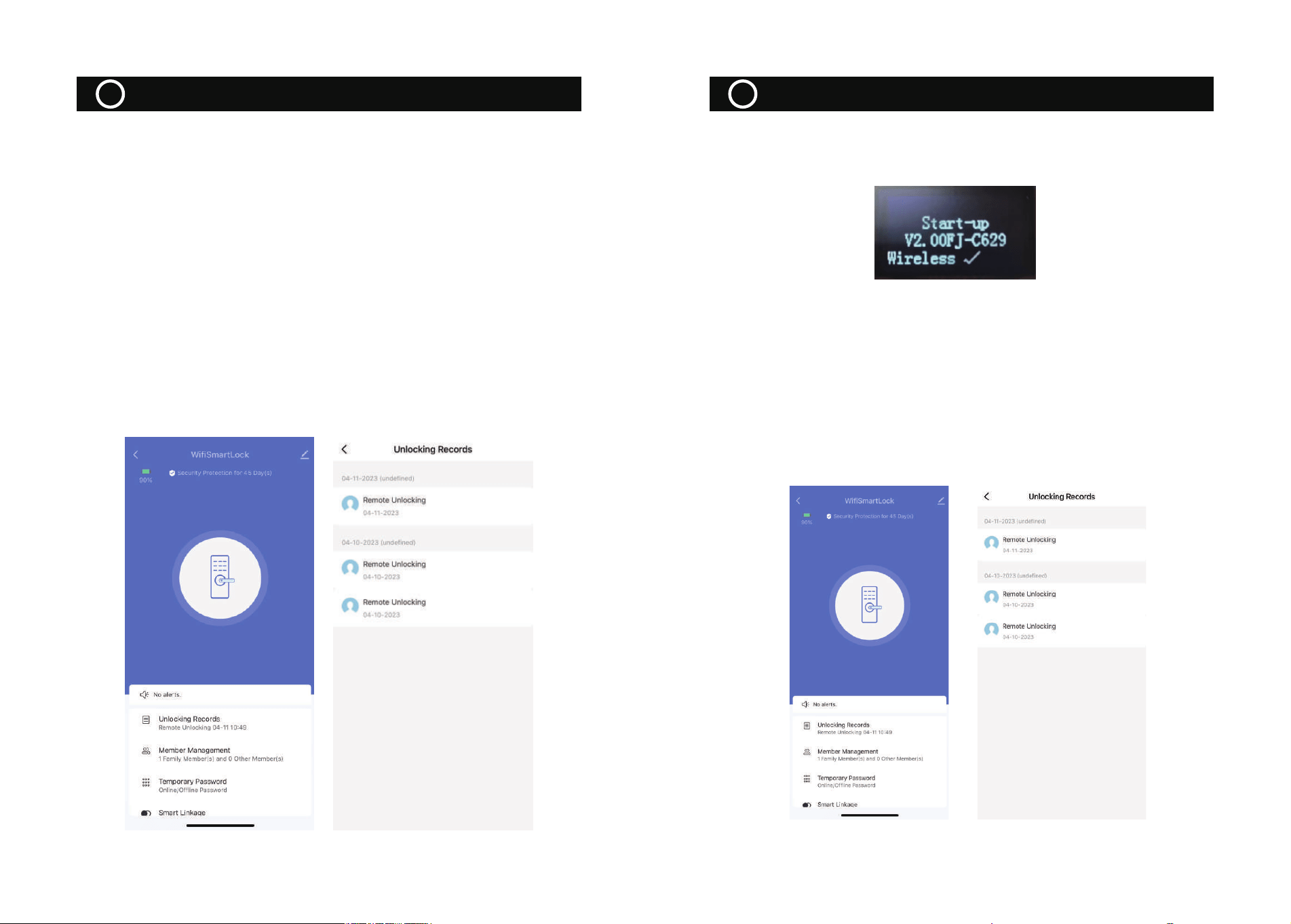
① Ensure that the WIFI module is connected to the cloud and the app can
view the device
② Press "9" + "#" at the door lock to wake up the graffiti module, the
module indicator will light up. (Some of the door locks are touch bright that
wakes up the module, do not need to press 9#, please operate according to
the actual situation).
③ The button of "click to open the door remotely" will appear on the home
page of the APP interface, and will confirm whether to open the lock after
clicking;
④After confirming the unlocking, the door lock will be unlocked, and the
APP will have the record of remote unlocking reported (Note: The initialized
state has no record reported, and a user needs to be entered to have the
open door record reported).
①First ensure that the wireless module has been detected on the door lock
side, specifically to see the detection information at power-up, as follows;
②Ensure that the time at the door lock is accurate with Beijing time, if the
door lock time is not set, please manually enter the administrator setting
interface to set the correct time (Note: Some screenless devices do not
have time display or broadcast, you can ignore this step);
③Click on "Temporary Password" under the remote dynamic password on
the APP side to get the password;
4.Enter the dynamic password, unlock the door lock end after successful
verification, and report the unlocking record.
One-Time Password
6
Remote Unlock Function
5
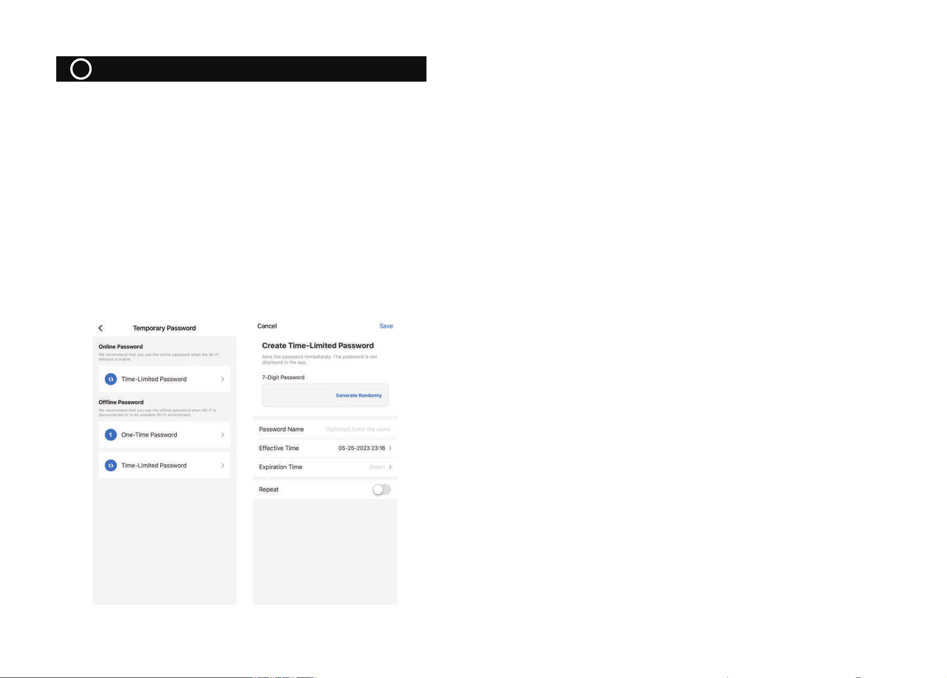
①Similar to the One-Time password, first ensure that the wireless module
is detected on the door lock side and that the time is calibrated;
②Create a temporary password in the APP, enter the password, name and
valid time, and it will show "To be issued" after creation;
③ Click “Time- Limited Password”,press “Add”and then edit name and
select temporary password usage time
④Enter the temporary password, and after successful verification, the door
lock end will be unlocked and report the door opening record. (Note:
Unlike the dynamic password, there is no need to enter the password after
waking up the module here)
Note: The temporary password can be unlocked unlimited times within the
valid time period
TiTTime—Limited Passwordme
7

This device complies with part 15 of the FCC Rules. Operation is subject to the
following two conditions: (1) This device may not cause harmful interference, and (2)
this device must accept any interference received, including interference that may cause
undesired operation.
Any Changes or modifications not expressly approved by the party responsible for
compliance could void the user's authority to operate the equipment.
Note: This equipment has been tested and found to comply with the limits for a Class B
digital device, pursuant to part 15 of the FCC Rules. These limits are designed to
provide reasonable protection against harmful interference in a residential installation.
This equipment generates uses and can radiate radio frequency energy and, if not
installed and used in accordance with the instructions, may cause harmful interference
to radio communications. However, there is no guarantee that interference will not
occur in a particular installation. If this equipment does cause harmful interference to
radio or television reception, which can be determined by turning the equipment off and
on, the user is encouraged to try to correct the interference by one or more of the
following measures:
-Reorient or relocate the receiving antenna.
-Increase the separation between the equipment and receiver.
-Connect the equipment into an outlet on a circuit different from that to which the
receiver is connected.
-Consult the dealer or an experienced radio/TV technician for help.
-This equipment complies with FCC radiation exposure limits set forth for an
uncontrolled environment. This equipment should be installed and operated with
minimum distance 20cm between the radiator & your body.