
EG10 High-Precision Excavator
Guidance System Manual
Core Summary: The EG10 High-Precision Excavator Guidance System
integrates GNSS high-precision positioning, external IMU attitude sensing,
and CAD design data to visualize design results in real-time on the excavator
operation screen, achieving construction processes without manual stakeout,
with high-precision guidance. This system is specifically designed for earthwork
operations such as slope trimming, trenching, and leveling, effectively solving
traditional construction problems that rely on manual measurement and have
difficulty ensuring precision, thereby improving construction efficiency and quality.
Product Overview
The EG10 High-Precision Excavator Guidance System is an intelligent construction
solution specifically designed for engineering machinery. By integrating centimeter-
level GNSS positioning, high-precision IMU attitude sensing, and professional
construction guidance software, the system maps design drawings in real-time to
the excavator operation interface, allowing operators to intuitively and precisely
control bucket position, achieving stakeout-free construction with what-you-see-
is-what-you-get effects.
Core Advantages of EG10 System:
• High-precision construction: Centimeter-level positioning accuracy ensures
construction quality
• Efficiency improvement: Reduces manual stakeout time, increases
construction efficiency
• Easy operation: Intuitive graphical interface reduces reliance on skilled
operators
• Wide applicability: Suitable for various earthwork operations including slope
trimming, trenching, leveling, foundation pit excavation
This system is applicable to various earthwork scenarios, including but not limited to
slope trimming, trenching, leveling, foundation pit excavation, etc., significantly
improving construction accuracy, reducing rework, and decreasing reliance on skilled
operators.
Appearance Illustration and Structure
Introduction
Overall System Appearance Layout
The EG10 system hardware consists of four core components that work together to
achieve high-precision guidance functions. The typical installation positions of each
component on the excavator are as follows:
○ External IMU: Installed on the excavator bucket, serving as the core attitude
sensor of the system
○ Mounting bracket: Used to secure IMU, receiver and other equipment, providing
a firm installation foundation
○ V10a receiver: Typically installed on the cab roof or boom open area, providing
positioning reference
○ T10 tablet: Installed in the driver's cab, serving as the human-machine interface
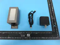
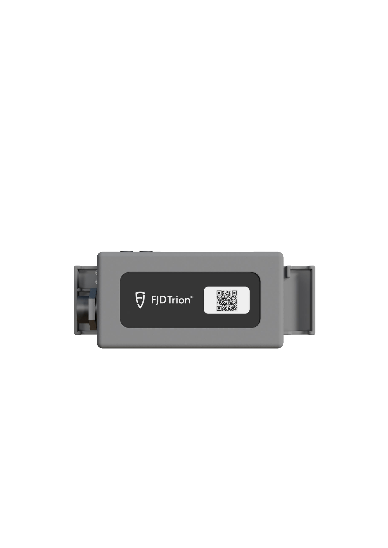
External IMU Device Appearance
External IMU Detailed Structure
The external IMU is the key component for the EG10 system to achieve high-
precision bucket attitude sensing, with its structural design fully considering the
harsh operating environment of engineering machinery.
Core Structural Features:
• Sensor configuration: Uses industrial-grade 6-axis sensors (3-axis
accelerometer + 3-axis gyroscope), capable of precisely measuring bucket pitch

angle and roll angle
• Connection method: Equipped with quick-detachable "dog bone" connectors,
supporting welding-free installation, greatly simplifying deployment process
• Protection rating: Housing uses high-strength engineering plastic, interfaces
equipped with waterproof and dustproof sealing rings, adapting to dusty, humid
construction site environments
• Installation flexibility: Can adapt to different types of mounting brackets
through adapter seats, meeting various excavator installation requirements
Diagram Annotation Description:
○ Status indicator light: Multi-color LED indicator light, displaying device working
status
○ Waterproof data interface: Used to connect power and data transmission cables
○ "Dog bone" connector: Key component for quick installation and removal
○ Device fixed housing: High-strength shell protecting internal precision sensors
Indicator Light Status Detailed Explanation
The indicator lights of the EG10 system are important for judging device working
status, with both external IMU and V10a receiver equipped with multi-status indicator
lights.
Power and Working Status Indication
• Green steady light: Device powered normally, in standby or stable working state
• Red steady light: Power fault or voltage abnormality, need to immediately check
power supply circuit
• Indicator light not lit: Device not powered or power connection fault
• Green slow flash (approximately 1 second per flash): Device starting up or
initializing
• Green fast flash (approximately 3 flashes per second): Device attempting to
establish data connection (such as IMU pairing with receiver/tablet)
• Blue steady or slow flash: Data connection stable, normally transmitting sensor
data
• Yellow flashing: Sensor data abnormal or system prompting need for calibration
• Red-green alternating flash: System detecting serious error, need to restart
device or contact technical support
Hardware Components

Core Hardware Priority
According to functional importance in the system, EG10 hardware components are
ranked by the following priority:
1. External IMU (Core Sensing Unit)
As the eyes of the system, the external IMU directly measures the spatial attitude of
the bucket, with its measurement accuracy and stability directly determining the
final construction guidance accuracy. Any installation looseness or calibration
deviation will cause guidance error.
2. Mounting Bracket (Physical Foundation)
Provides physical stability for device installation. The firmness of the bracket
directly affects IMU data reliability. The system provides magnetic fixation and
welding fixation methods, users should choose according to actual working
conditions.
Mounting Bracket Component Description:
• Bracket body: Main support structure
• Ring magnet: Strong magnetic suction disk for magnetic fixation method
• Threaded connectors: Used to connect IMU or other devices
• Adapter seat: Adapts to different device interfaces
Mounting Bracket Fixation Method Detailed
Explanation
Magnetic Fixation Method
• Working principle: Adsorbs onto excavator metal surface through strong
magnetic suction disk
• Installation requirements: Installation surface must be clean, dry, flat, free
from oil stains, rust or peeling paint
• Advantages: Quick installation and removal, no damage to original excavator
structure
• Applicable scenarios: Temporary engineering, equipment needing frequent
changes, or when excavator surface conditions are good
• Precautions: Under strongly vibrating working conditions, need secondary
reinforcement with binding straps
Welding Fixation Method

• Installation requirements: Professional welder fully welds bracket base to
appropriate position on excavator boom
• Advantages: Extremely firm connection, no loosening risk, suitable for long-
term high-intensity vibration conditions
• Applicable scenarios: Fixed-site long-term operations, uneven excavator
surface or heavy oil contamination preventing magnetic fixation
• Precautions: Clean welding slag after welding, apply anti-rust treatment
Selection recommendation: For most construction scenarios, especially those with
strong vibration, strongly recommend using welding fixation method to obtain
optimal long-term stability and data reliability.
Installation Instructions
Safety Warning: All installation or removal operations must be performed with the
excavator engine completely shut off, equipment parked on flat, solid ground,
and ensuring all moving parts (boom, bucket, etc.) are properly secured.
Installation operations are strictly prohibited while the excavator is running or
without taking safety measures.
Pre-installation Preparation
○ Equipment inspection: Unbox and check all hardware (IMU, bracket, receiver,
tablet, cables) for completeness and no visual damage
○ Site preparation: Park excavator on flat, solid ground, perform safety operations
such as shutdown, parking brake
○ Surface treatment: Plan installation positions (outer side of boom, cab roof),
thoroughly clean surface oil stains, mud and surface rust with sandpaper and cleaner
Step-by-Step Installation Process
Step 1: Mounting Bracket Fixation
Magnetic method operation:
○ Press magnetic suction disk against cleaned installation surface
○ Apply force to ensure firm adsorption, check for no shaking
○ Can perform secondary reinforcement with binding straps if needed
Welding method operation:
○ Professional welder welds bracket base to specified position
○ Ensure welding is firm and flat

○ Allow cooling after welding, clean welding slag
Step 2: External IMU Installation
○ Insert IMU's "dog bone" connector into adapter seat at end of bracket, hearing
"click" sound indicating locking
○ Adjust IMU angle so arrow on housing roughly points toward excavator forward
direction
○ Tighten fixing screws, ensure IMU has no shaking
○ Connect IMU power and data cables, ensure interfaces are fully inserted and
waterproof screw caps are tightened
Step 3: V10a Receiver Installation
○ Install receiver onto bracket on cab roof or boom upper area
○ Ensure antenna faces sky, with unobstructed view (away from large metal
structures)
○ Connect cables and ensure firm connection
Step 4: T10 Tablet Installation
○ Fix tablet bracket inside cab at position convenient for operator observation and
not prone to collision
○ Place tablet into bracket slot, adjust to suitable viewing angle
○ Connect power cable
Step 5: Wiring Connection and Cable Management
○ Connect all cables (power, data) between devices according to system
connection diagram
○ Use cable ties to neatly bundle cables
○ Route cables along existing excavator wire harness or structural components,
avoid suspension or being squeezed, scraped by moving parts
Post-installation Checklist
After installation completion, please check the following items in sequence, only
power on after confirming all are correct:
□ All devices (IMU, receiver, bracket) firmly fixed, no shaking when forcefully rocked
□ All waterproof interfaces tightened
□ Cable routing safe, no sharp bends, stretching or wear risk

□ Receiver installation position meets open, unobstructed requirement
□ IMU installation direction roughly correct (arrow pointing forward)
□ Tablet installation position convenient for operator observation and safe
Calibration Operations
Calibration is the key step to establish an accurate mathematical model between
excavator physical dimensions, joint motion relationships and sensor data. All
calibration operations must be performed on level, solid ground.
Boom Calibration
This step is used to calibrate excavator boom and arm geometric parameters,
establishing mechanical arm motion model.
Pre-calibration preparation:
• Ensure excavator parked on level, solid ground
• Confirm IMU installation firm, no looseness
• Prepare measuring tape for measurements
Calibration steps:
Input basic parameters
○ Accurately input excavator boom length in T10 tablet software
○ This value should be pin center to pin center distance, must match
excavator model specifications
Bucket ground contact position calibration
○ Place bucket flat, completely pressed against ground
○ Confirm this position as reference zero point in software
Boom motion range calibration
○ Retract boom inward to mechanical limit position (cannot move further
inward)
○ Confirm this position in software
○ Extend boom outward to mechanical limit position (cannot move further
outward)
○ Confirm this position in software
Vertical position calibration
○ Operate boom so line connecting bucket pin center and excavator swing
center is perpendicular to ground
○ Can use simple plumb bob to assist in judging verticality

○ Confirm this position in software
Calibration success indication: Software interface displays "Boom calibration
successful", providing accuracy evaluation value. If display fails, check if all positions
are accurately calibrated.
Bucket Calibration
This step is used to calibrate bucket geometric dimensions, especially critical D-I
value (straight-line distance from bucket pin center to tooth tip).
Calibration steps:
Select bucket model
○ Select bucket template in software accessory library that exactly matches
actual bucket model
○ If no corresponding model in library, select closest matching template
Move to limit positions
○ Operate bucket to fully closed limit position
○ Confirm this position in software
○ Operate bucket to fully open limit position
○ Confirm this position in software
Measure and input D-I value
○ Using measuring tape, precisely measure straight-line distance from
bucket pin center to tooth tip when bucket is fully open
○ Accurately input measured value into software specified field
○ Recommend measuring three times and taking average to ensure accuracy
Complete calibration
○ Follow remaining software prompts to complete steps
○ Until "Bucket calibration successful" displayed
Calibration Verification and Troubleshooting
Verification method:
• After calibration completion, slowly operate excavator various movements (boom
up/down, arm extend/retract, bucket rotate)
• Observe whether bucket icon movement on tablet screen is continuous,
synchronized, without jumps with real bucket movement
• If significant deviation found, need to recalibrate
Common failure causes and countermeasures:

Problem Phenomenon
Possible Cause
Solution Measures
Boom calibration failure
Ground not level
Move excavator to level
ground and retry
Boom calibration cannot
complete
Boom not moved to true
mechanical limit
Ensure movement
reaches limit position,
mechanical stop reached
Parameter error prompt
Input boom length does
not match actual
Verify excavator model
specifications, input
correct parameters
Bucket D-I value
abnormal
Measurement taken
when bucket not at fully
open limit position
Re-operate bucket to limit
position then measure
Large deviation after
calibration during
operation
IMU installation position
shifted after calibration
Check and tighten IMU
installation, recalibrate
System prompts need
recalibration
Equipment reinstalled
after removal or
construction site changed
Execute complete
calibration process
Important reminder: Every time construction site changed, or any hardware
reinstalled or removed, must re-execute complete boom and bucket calibration
process.
Usage Precautions
Daily Usage Precautions
Power management
○ Check device battery level before startup, below 20% should charge
promptly
○ Avoid operation interruption and data loss due to battery depletion
○ Use device original charger for charging
Device operation
○ Avoid using sharp objects to operate tablet touchscreen
○ During device operation, strictly prohibit hot-plugging any data or power

interfaces
○ If displayed positioning deviation on tablet suddenly and continuously
increases, immediately stop operation, check device connections
Environmental adaptability
○ Device operating temperature typically -20℃~60℃, avoid prolonged
exposure to extreme temperatures or direct sunlight
○ Prevent device contact with large amounts of water or mud, clean with dry
cloth
○ Prohibit direct water flushing of core components (IMU, receiver)
Electromagnetic environment
○ Devices should be kept away from strong electromagnetic interference
sources such as large generators, welding machines
○ Avoid prolonged operation under high-voltage power lines
Regular Maintenance Points
Cleaning maintenance
○ Regularly clean device housing, screen and magnetic suction disk
surface with dry cloth
○ Remove dust, oil stains, keep equipment clean
○ Check waterproof interface sealing rings for integrity
Tightness inspection
○ Weekly or every 50 operating hours, check all brackets, connectors for
tightness
○ Pay special attention to IMU installation firmness, prevent loosening due to
vibration
○ Check cables for wear, aging signs
Long-term storage
○ If equipment long-term idle, maintain battery level at 50%-70%
○ Perform supplemental charging every 2-3 months, prevent battery over-
discharge
○ Store in dry, cool place, avoid high temperature, high humidity environments
Safety Operation Specifications
Pre-operation inspection
○ Check equipment installation firmness before each operation
○ Confirm indicator light status normal

○ Verify system positioning accuracy meets requirements
Operation monitoring
○ Maintain attention to information displayed on tablet
○ If abnormal prompts or accuracy decrease found, timely pause operation for
troubleshooting
○ Avoid forcing operation under abnormal system status
Equipment disposal
○ Prohibit users from self-disassembling, modifying device internal
structure
○ Any faults please directly contact FJDynamics official after-sales service
○ Discarded equipment should be disposed according to electronic waste
processing specifications
Common Problem Solutions
Installation Problems
Problem 1: Bracket magnetic suction not firm, easily loosens during operation
Possible causes:
Installation surface has oil stains, rust or paint layer
Magnetic components demagnetized due to long-term use or impact
Installation surface uneven, insufficient contact area
Solution measures:
Use sandpaper and cleaner to thoroughly clean oil stains, rust from installation
surface
If magnetic force significantly weakened, contact after-sales service to replace
new magnetic accessories
Consider switching to welding fixation method, especially for long-term high-
intensity operation scenarios
Problem 2: After external IMU installation, software shows no IMU signal
Possible causes:
IMU data interface not fully inserted or waterproof screw cap not tightened
Data cable connecting IMU damaged or poor contact
IMU device not powered or power supply fault
Solution measures:
Check and re-insert all IMU interfaces firmly, ensure waterproof screw caps

tightened
Replace data cable for testing, troubleshoot cable problems
Check IMU power connection, confirm power supply normal
Calibration Problems
Problem 3: Boom calibration failure or cannot complete calibration process
Possible causes:
Calibration ground uneven, causing reference position error
During calibration, boom not moved to true mechanical limit position
Input boom length parameters don't match actual excavator dimensions
Solution measures:
Move excavator to level, solid ground and recalibrate
During operation ensure boom reaches mechanical limit, cannot move further
Verify excavator model specifications, input correct boom length parameters
Problem 4: Bucket D-I value measurement abnormal or no change after
calibration
Possible causes:
Measurement taken when bucket not at fully open limit position
Measuring tool inaccurate or measurement method incorrect
Wrong bucket model selected
Solution measures:
Re-operate bucket to fully open limit position then measure
Use standard measuring tape, measure straight-line distance from pin center to
tooth tip precisely
Re-select correct bucket model in software accessory library
Problem 5: After calibration success, find large guidance deviation during
actual operation
Possible causes:
IMU installation position accidentally shifted after calibration completion
Calibration steps performed incorrectly, need recalibration
Construction ground slope differs significantly from calibration ground
Solution measures:
Immediately stop operation, check IMU installation firmness, retighten
On level ground, re-execute complete boom and bucket calibration

If construction ground has slope, need to set corresponding ground reference in
software
Signal and Connection Problems
Problem 6: V10a receiver has no GNSS signal or weak signal
Possible causes:
Receiver installation position obstructed (such as close to cab, under trees)
Local satellite signal conditions poor (canyons, high-rise areas)
Receiver antenna connection fault
Solution measures:
Move receiver to more open position, ensure antenna faces sky
Wait for satellite signal conditions improvement, or change operation time
Check antenna connection firmness, re-plug if necessary
Problem 7: IMU data transmission unstable, intermittent
Possible causes:
Data cable connecting IMU damaged or excessively bent
Device power supply unstable, voltage fluctuations large
Wireless transmission subject to strong interference
Solution measures:
Check and organize cables, avoid sharp bends, replace data cable if necessary
Check excavator power system, ensure stable power supply
Investigate surrounding strong interference sources, adjust device position if
necessary
Problem 8: Tablet cannot search or connect to IMU/receiver
Possible causes:
IMU or receiver Bluetooth/Wi-Fi not enabled or not in pairing mode
Distance between devices too far, exceeding wireless transmission range
Tablet software not granted Bluetooth/Wi-Fi connection permissions
Solution measures:
Confirm IMU/receiver powered on and in pairing mode (indicator fast flashing)
Shorten distance between devices, ensure within effective transmission range
Check tablet system settings, ensure software granted necessary connection
permissions

FCC Warning
NOTE: This equipment has been tested and found to comply with the limits for a
Class B digital device, pursuant to part 15 of the FCC Rules. These limits are
designed to provide reasonable protection against harmful interference in a
residential installation. This equipment generates, uses and can radiate radio
frequency energy and, if not installed and used in accordance with the
instructions, may cause harmful interference to radio communications. However,
there is no guarantee that interference will not occur in a particular installation. if
this equipment does cause harmful interference to radio or television reception,
which can be determined by turning the equipment off and on, the user is
encouraged to try to correct the interference by one or more of the following
measures:
--Reorient or relocate the receiving antenna.
--Increase the separation between the equipment and receiver.
--Connect the equipment into an outlet on a circuit different from that to which the
receiver is connected.
--Consult the dealer or an experienced radio/TV technician for help.
Any changes or modifications not expressly approved by the party responsible
for compliance could void the user's authority to operate the equipment.
This device complies with part 15 of the FCC Rules. Operation is subject to the
following two conditions:
(1)This device may not cause harmful interference, and
(2) This device must accept any interference received, including interference that
may cause undesired operation.
This equipment complies with FCC radiation exposure limits set forth for an
uncontrolled environment. This equipment shall be installed and operated with
minimum distance 20cm between the radiator& body.