
1. INTRODUCTION
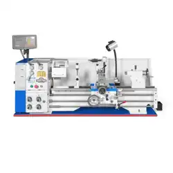
Thank you for choosing the MechMaxx 1337G4 Bench Lathe—a precision-engineered machine built for a wide
range of metalworking operations, including turning, facing, drilling, and thread cutting. With a large 40 mm spindle
bore, 13" swing over bed, and 37" between centers, the 1337G4 offers generous working capacity for small workshops,
repair facilities, and serious home machinists.
Unlike models equipped with Norton-style quick-change gearboxes, the 1337G4 utilizes a robust 4-lever sliding gear
system to control spindle speeds and threading. This direct gear-driven design emphasizes mechanical simplicity,
durability, and long-term reliability.
The lathe is constructed from high-grade cast iron and includes the following precision features:
Hardened and ground bedways for long-term accuracy and wear resistance.
Fully supported leadscrew and feed rod for smooth feed and threading.
Precision-machined handwheels with graduated dials for repeatable adjustments.
Threading dial indicator for inch threads.
Rigid carriage and apron assembly with adjustable gibs.
Electrical Requirements:
220V, single-phase, 60 Hz power supply. A properly grounded outlet must be used. No plug is supplied; user
installation is required by a qualified electrician.
Please read this manual thoroughly before operating the lathe. Understanding all safety precautions and operating
procedures will ensure years of reliable performance and accurate results.

2. SPECIFICATIONS
Item
Specification
Model Number
1337G4
Brand
MechMaxx
Swing Over Bed
13" (330 mm)
Swing Over Cross Slide
7-1/2" (190 mm)
Distance Between Centers
37" (940 mm)
Spindle Bore
1.57" (40 mm)
Spindle Nose
D1-4 Camlock
Spindle Taper (Internal)
MT #5
Tailstock Taper
MT #3
Tailstock Quill Travel
4" (100 mm)
Motor
3 HP, 220V, 1-Phase, 60 Hz
Spindle Speed Range
70–2000 RPM (9-step sliding gear)
Cross Slide Travel
5.9" (150 mm)
Compound Rest Travel
3-1/8" (80 mm)
Leadscrew
Ø0.87" (22 mm), 8 TPI
Feed Rod
Ø0.75" (19 mm)
Inch Thread Range
8–56 TPI
Metric Thread Range
0.4–3.0 mm
Longitudinal Feed Rates
0.002 – 0.032 in./rev.
Approx. Net Weight
1800 lbs (820 kg)
Overall Dimensions (L×W×H)
76" × 30" × 60" (1930 × 760 × 1520 mm)
Specifications are subject to change without notice. Always verify current specs with distributor if critical.

3. SAFETY INSTRUCTIONS
Proper safety practices are essential when operating a metal lathe. Always read and follow the instructions in this
manual to avoid injury and damage to the machine.
3.1 General Safety Guidelines
Read this manual thoroughly before operating the lathe.
Do not operate the machine under the influence of drugs, alcohol, or medication.
Keep work area clean, dry, and well-lit.
Wear safety glasses with side shields and appropriate clothing. Do not wear loose garments, jewelry,
or gloves near rotating parts.
Tie back long hair to prevent entanglement.
Keep hands away from moving parts. Never reach over the rotating chuck or workpiece.
Disconnect power before adjusting, cleaning, or servicing the machine.
Only trained or experienced personnel should operate the lathe.
3.2 Machine Setup Safety
Ensure the machine is installed on a solid, level surface and anchored if necessary.
Properly ground the lathe according to electrical codes.
Verify that the spindle rotates in the correct direction before operation.
Check that all guards and covers are in place and secure.
Always stop the spindle before changing speeds or engaging feed mechanisms.
3.3 Operating Safety
Use the correct cutting tools and speeds for your material.
Tighten workpieces securely in the chuck or faceplate. Use tailstock support for long or unbalanced parts.
Never leave the machine running unattended.
Do not attempt to stop the chuck or spindle by hand.
Do not exceed the rated capacity of the machine.
3.4 Maintenance Safety
Disconnect power before any maintenance or service work.

Allow the spindle and motor to fully stop before opening covers or changing belts/gears.
Use only recommended lubricants and replacement parts.
Keep all moving parts clean and lubricated.
3.5 Electrical Safety
This lathe requires 220V, single-phase, 60 Hz power.
Only qualified personnel should access or service the electrical box.
Never operate with damaged cords, plugs, or switches.
3.6 Emergency Readiness
Know the location of the Emergency Stop and how to use it.
Keep a fire extinguisher nearby and ensure it's appropriate for electrical and oil fires (Class C/B).
Have a first-aid kit available in your shop.
Failure to follow safety instructions may result in serious injury or death. MechMaxx is not responsible for
damage or injury resulting from misuse of the machine.

4. INSTALLATION & SETUP
Proper installation is essential to ensure the safety, accuracy, and long-term performance of your lathe. Follow the
procedures below before operating the machine.
4.1 Unpacking and Handling
Carefully remove the lathe and all included accessories from the shipping crate.
Inspect all components for shipping damage. Report any issues to your dealer immediately.
Do not discard the packaging until the lathe is fully installed and tested.
Use a forklift or hoist rated for at least 1200 lbs (550 kg).
When lifting, use nylon straps under the bed casting or through designated lifting points (if equipped).
Never lift the machine using the chuck, lead screw, or control handles.
4.2 Site Requirements
Install the lathe on a solid, level concrete floor, free from vibration.
Ambient temperature: 41–95°F (5–35°C).
Allow at least 24" (600 mm) of clearance around the machine for access and maintenance.
Ensure lighting is sufficient to illuminate the working area.
4.3 Mounting the Lathe
If using a factory stand (optional accessory), align the mounting holes and secure the lathe using the provided
bolts.
If mounting to a workbench, ensure the surface can support at least 1200 lbs (550 kg).
The lathe stand is available for purchase on the official MechMaxx website.
4.4 Leveling the Machine
Accurate leveling improves performance and reduces wear on the carriage and ways.
Use a 6" machinist’s precision level with sensitivity of at least 0.0005"/10".
Leveling procedure:
1. Place the level along the bedways in the longitudinal (Z-axis) direction.
2. Adjust leveling feet or shim points until the bubble is centered.
3. Repeat across the bed (X-axis) and re-check.

4. Re-check after 24–48 hours of use, as settling may occur.
Do not use a carpenter’s level. Precision leveling is essential for machining accuracy.
4.5 Electrical Requirements
Voltage: 220V, single-phase, 60 Hz
Circuit Requirement: Minimum 15A dedicated circuit
Grounding: A properly grounded outlet is required.
IMPORTANT:
The machine does not include a power plug. The user must install an appropriate plug or connect the wiring
directly to a suitable junction box.
All wiring must be performed by a qualified electrician, in compliance with local electrical codes.
Ensure the machine is properly grounded to avoid risk of electrical shock.
Before powering on:
o Verify that the spindle direction switch is in the center (OFF) position.
o Check that all controls are off.
o
After connecting power, confirm correct spindle rotation (clockwise when viewed from tailstock).

5. OPERATIONS
This chapter describes the operating procedures for the MechMaxx 1337G4 lathe. Unlike quick-change gearbox lathes,
the 1337G4 uses a traditional 4-lever sliding gear system located on the headstock to control spindle speed, feed rate,
and threading configurations. The machine is also equipped with a feed rod for power feed and a leadscrew for
threading.
5.1 Control Panel Overview
The 1337G4 lathe features the following control elements located on the front panel:
Control Element
Description
Power Switch (Finger-Safe)
Turns the machine ON/OFF. Includes safety cover.
Power Indicator Light
Illuminates when the machine is powered.
Emergency Stop Button
Immediately cuts off all power for emergency shutdown.
Inching Button (Jog)
Activates momentary spindle rotation for precise setup.
Spindle Direction Lever
Selects spindle rotation: FORWARD / REVERSE / STOP.
AB Selector Lever
Primary spindle speed range selector (low/high).
1234 Selector Lever
Secondary spindle speed selector (fine steps).
CD Selector Lever
Threading/feed configuration lever 1 (mode group selector).
RSTV Selector Lever
Threading/feed configuration lever 2 (fine pitch/feed selector).
Always ensure the spindle is at a complete stop before shifting any levers.
5.2 Spindle Speed Selection
Spindle speed is set using two levers:
AB Lever: Selects one of the main speed ranges (A or B)
1234 Lever: Selects a sub-range (1 to 4)
This combination provides a total of 8–12 gear combinations (refer to speed chart on headstock for exact RPM
values).
To Change Speed:
1. Stop the spindle completely.
2. Move both levers (AB and 1234) to the desired position.

3. Restart the spindle.
Never shift levers while the spindle is rotating.
5.3 Feed and Threading Control (4-Lever Gearbox)
Feed and threading operations are configured using:
CD Lever: Sets feed/threading group (coarse/fine)
RSTV Lever: Sets specific feed rate or thread pitch within the group
Depending on your machine’s chart, this system allows selection of:
Inch threads: 8–56 TPI
Metric threads: 0.4 – 3.0 mm
Feed rates: 0.002 – 0.032 in./rev
Feed Rod vs Leadscrew:
Feed Rod: Used for longitudinal power feed.
Leadscrew: Used for threading only.
Machines like the 1337G4 do not have a selector knob for switching between feed rod and leadscrew; each is driven
independently via internal gearing.
5.4 Carriage Operation
Longitudinal Movement (Z-axis): Via feed rod or manually using carriage handwheel.
Cross Slide (X-axis): Manually moved via handwheel.
Compound Rest: Adjustable angle for taper turning.
Use the half-nut lever only when threading with the leadscrew.
5.5 Thread Cutting
Thread cutting setup involves:
1. Select correct gear settings using CD + RSTV levers.
2. Refer to threading chart for pitch combinations.
3. Engage half-nut lever during threading pass.
4. Use threading dial indicator (inch threads only).
Always disengage the half-nut and stop the spindle before reversing.

5.6 Tailstock Operation
1. Slide tailstock along bedway and lock in place.
2. Extend quill using handwheel.
3. Lock quill when in position.
4. Tailstock can be offset for taper turning.
5.7 Tool Post and Tool Setup
The machine includes a 4-way tool post:
Insert cutting tool and adjust height as needed.
Lock in place and rotate turret for tool changes.
Always check tool height and sharpness before starting a cut.

6. MAINTENANCE AND LUBRICATION
Regular maintenance and proper lubrication are essential to keep your MechMaxx 1337G4 lathe operating safely and
precisely. Follow the guidelines below to ensure longevity and reliability.
6.1 Daily Maintenance
Clean the machine surfaces with a lint-free cloth after each use.
Remove chips and debris from the bed, carriage, and tool post.
Apply light machine oil to exposed metal surfaces to prevent rust.
Inspect oil sight glasses (if equipped) for adequate lubrication levels.
6.2 Lubrication Points and Intervals
Component
Lubricant Type
Frequency
Headstock Gears
ISO 220 Gear Oil
Every 6 months
Apron Gears
ISO 68 Slideway Oil
Monthly
Leadscrew & Feed Rod
ISO 68 Slideway Oil
Weekly
Cross Slide & Compound
ISO 68 Slideway Oil
Weekly
Tailstock Quill
ISO 68 Slideway Oil
Weekly
Chuck (Scroll & Jaws)
Light Machine Oil
Daily or as needed
Guideways (Bed)
ISO 68 Slideway Oil
Daily before use
Grease Fittings (if equipped)
NLGI #2 Grease
Monthly
Always stop the machine and disconnect from power before performing any lubrication or cleaning tasks.
6.3 General Maintenance Checklist
Check for unusual noise or vibration during operation.
Inspect belts and gears for wear or damage.
Verify tightness of gibs, nuts, and fasteners.
Confirm function of emergency stop and control switches.
Drain and replace headstock oil every 6–12 months or 500 hours of use.

6.4 Storage and Rust Prevention If the machine will not be used for an extended period:
Coat machined surfaces with rust-preventive oil.
Cover the machine with a breathable dust cover.
Store in a dry, temperature-stable environment.
Proper maintenance will ensure your MechMaxx 1337G4 continues to provide accurate and dependable performance
for years to come.
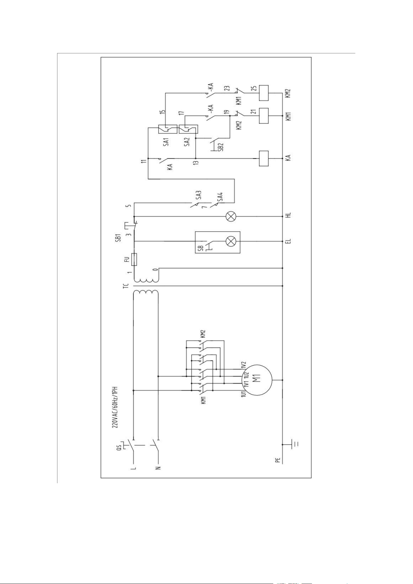
7. Circuit Diagram
