In locations used for the storage of combustible materials, signs
must be posted to specify the maximum permissible stacking
height to maintain the required clearances from the heater to
the combustibles. Signs must either be posted adjacent to the
heater thermostats or, in the absence of such thermostats, in a conspicuous
location.
Keep these instructions for future reference.
Please read and save these instructions. This heater must be installed and serviced by trained gas installation and service
personnel only! Read carefully before attempting to assemble, install, operate, or maintain the product described. Protect
yourself and others by observing all safety information. Failure to comply with instructions could result in personal injury
and/or property damage! Retain these instructions for future reference.
Form 5S6496 Printed in U.S.A.
03460
1109/224/VCPVP
Dayton Tube Heaters
®
Description
Dayton tube heaters are gas-red infrared heaters designed to provide comfort
heat. They consist of three (3) main components: a burner control box, radiant
tube, and reector assembly. The heaters are typically suspended from the ceiling
by chains and controlled by a thermostat. They can be installed either vented or
unvented, and may use outside air for combustion if necessary. The radiant tube
may be installed in different congurations depending on the heating requirements.
These heaters use infrared energy to heat spaces. When heat is required, the
burner control box ignites a gas/air mixture and pushes the hot gases into the
radiant tube. As the gases pass through the assembly, the tubing is heated
and emits infrared, which is then directed toward the oor by reectors. This is
known as primary infrared and is absorbed by the oor, objects and people in
the space, raising their temperatures. They in turn re-radiate this heat, known as
secondary infrared, to create a comfort zone at the oor level. This is how Dayton
tube heaters can heat large spaces without having to provide primary infrared
for every square foot of area. However, if the goal is to spot heat a small area
within a large space, only the primary infrared makes this possible. Dayton tube
heaters are design certied for use in industrial and commercial buildings, such
as warehouses, manufacturing plants, aircraft hangars and vehicle maintenance
shops. They are not certied for residential use or where ammable gases or
vapors are generally present, such as spray booths.
• Do not try to light any appliance.
• Immediately call your gas supplier
from a neighbor’s phone.
• Do not touch any electrical switch.
• Follow the gas supplier’s
instructions.
• Do not use any phone in your
building.
• If you cannot reach your gas
supplier, call the re department.
For Your Safety - If you smell gas:
WARNING
!
!
Improper installation,
adjustment, alteration,
service, or
maintenance can
cause property
damage, injury, or death. Read and
understand the installation,
operating, and maintenance
instructions thoroughly before
installing or servicing this
equipment.
This heater must be installed and
serviced by trained gas installation
and service personnel only. Failure
to comply could result in personal
injury, asphyxiation, death, re, and/
or property damage.
WARNING
!
!
7D837A thru 7D849A, 7D851A,
7AR79 thru 7AR88
Installation, Operation, Maintenance, and Parts Manual
11/2025
Dayton Installation, Operation, Maintenance, and Parts Manual
Dayton Tube Heaters
®
7D837A thru 7D849A, 7D851A, 7AR79 thru 7AR88
2
TABLE OF CONTENTS
INTRODUCTION .................................................................................................................................................................... 3
Overview ........................................................................................................................................................................ 3
SAFETY .............................................................................................................................................................................. 4
Warning Symbols ............................................................................................................................................................ 4
Specic Applications ....................................................................................................................................................... 4
Standards, Certications, and Government Regulations ................................................................................................. 5
Clearances to Combustibles ........................................................................................................................................... 6
INSTALLATION .................................................................................................................................................................... 8
Design Considerations and Prechecks .............................................................................................................................. 8
Recommended Mounting Heights ...................................................................................................................................10
Hanger Placement and Suspension ..................................................................................................................................11
Optional U-Bend or Elbow Accessory Conguration ........................................................................................................ 14
Radiant Tube Assembly ...................................................................................................................................................15
Burner Control Box Suspension ...................................................................................................................................... 18
Reector Assembly ..........................................................................................................................................................19
Bafe Assembly and Placement .......................................................................................................................................21
Final Heater Assembly ..................................................................................................................................................... 22
Venting ...........................................................................................................................................................................23
Combustion Air Requirements ........................................................................................................................................30
Gas Supply .....................................................................................................................................................................32
Electrical Requirements ...................................................................................................................................................35
OPERATION ..........................................................................................................................................................................37
MAINTENANCE ....................................................................................................................................................................38
Troubleshooting Guide ....................................................................................................................................................39
PARTS ..............................................................................................................................................................................40
Repair Parts Illustration ....................................................................................................................................................40
Repair Parts List ...............................................................................................................................................................41
LIMITED WARRANTY ...........................................................................................................................................................44
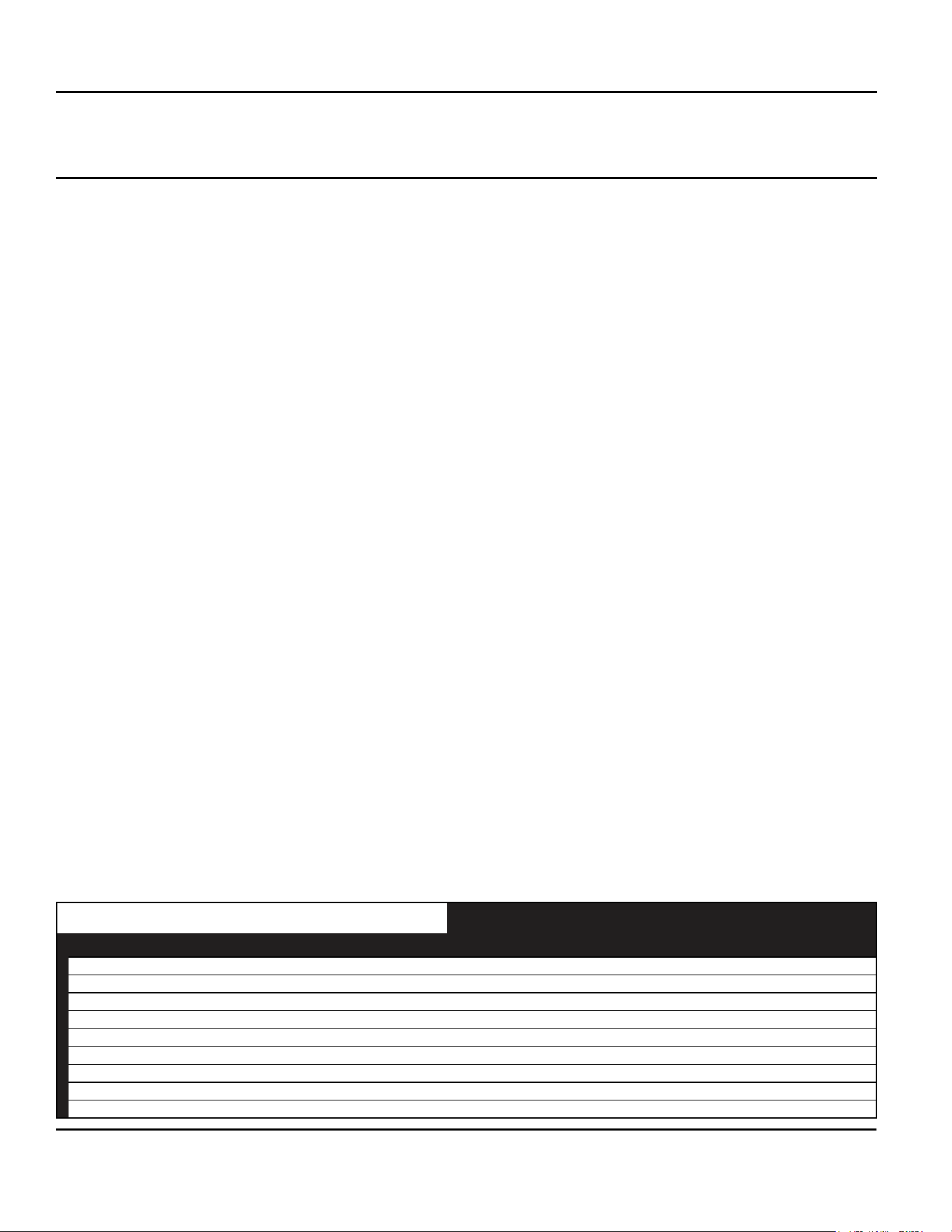
Prior to installation, verify that you have received all heater components included with your tube heater. Refer to the chart
below for a list of the kit contents for your model heater. Materials not included in the kit (e.g. sheet metal screws, vent
material, terminals, etc.) are the responsibility of the installer.
Kit Contents
Filled By:
5VD67A-
5VD70A
5VD71A-
5VD72A
5VD73A-
5VD78A
5EAJ0-J2,
5EAH3-H5
5VD79A-80A,
5EAH6-H8
Part # Description 20 ft. 30 ft. 40ft. 50ft. 60ft.
TP-19B
4” Tube Hanger with Tension Spring 3 4 5 6 7
TP-21B
4” Tube Clamp 2 3 4 5 6
TP-33B
1/2” Shut-off Ball Valve/Inlet Tap 1 1 1 1 1
TP-82
4” Reector Center Support 2 3 4 5 6
TP-83
24” Stainless Steel Flexible Gas Connector 1 1 1 1 1
TP-105
Reector End Cap 2 2 2 2 2
TP-106
Reector End Cap Clips 8 8 8 8 8
THCS
Tube Heater Chain Sets 5 6 7 8 9
IOM
Installation, Operation & Maintenance Manual 1 1 1 1 1
One 4” stainless steel tube clamp (P/N: TP-220) is provided for each 150,000 BTU/h model. Place as
shown on page 15. Models 5VD77A, 5VD78A, 5EAJ0, 5EAJ1, 5EAJ2, 5EAH3, 5EAH4 and 5EAH5.
Dayton Installation, Operation, Maintenance, and Parts Manual
Models 7D837A thru 7D849A, 7D851A, 7AR79 thru 7AR88
3
INTRODUCTION
Overview
The intent of this manual is to provide information regarding general safety, installation, operation, and maintenance of
this tube heater. You must read and understand all instructions and safety warnings before installing or servicing the tube
heater.
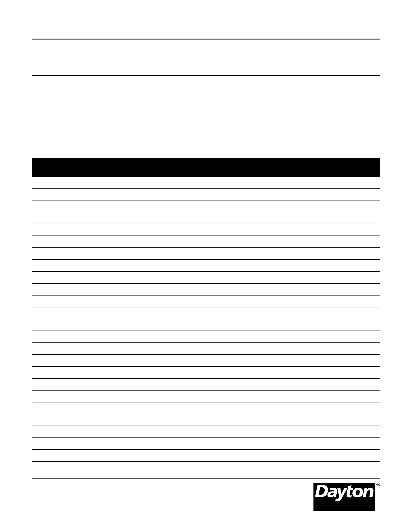
Available Models - Tube Heater Burner Box and Tube Reflector Combinations
Combo #
Burner
Box #
Tube &
Reector Pkg # Tube Type Length BTU/h
Bafe
Quantity Gas Type
7D837A 5VD67A 5VD88 20-4”-ALUM 20 50,000 5 NAT
7D838A 5VD68A 5VD88 20-4”-ALUM 20 50,000 5 PROP
7D839A 5VD69A 5VD88 20-4”-ALUM 20 75,000 5 NAT
7D840A 5VD70A 5VD88 20-4”-ALUM 20 75,000 5 PROP
7D841A 5VD71A 5VD89 30-4”-ALUM 30 100,000 5 NAT
7D842A 5VD72A 5VD89 30-4”-ALUM 30 100,000 5 PROP
7D843A 5VD73A 5VD91 40-4”-ALUM 40 100,000 4 NAT
7D844A 5VD74A 5VD91 40-4”-ALUM 40 100,000 4 PROP
7D845A 5VD75A 5VD91 40-4”-ALUM 40 125,000 4 NAT
7D846A 5VD76A 5VD91 40-4”-ALUM 40 125,000 4 PROP
7D847A 5VD77A 5VD90 40-4”-TITAN 40 150,000 4 NAT
7D848A 5VD78A 5VD90 40-4”-TITAN 40 150,000 4 PROP
7AR80 5EAJ0 5VD90 & 5EAH2 40-4”-TITAN & 10-4”-ALUM 50 150,000 4 NAT
7AR79 5EAJ1 5VD90 & 5EAH2 40-4”-TITAN & 10-4”-ALUM 50 150,000 4 PROP
7AR83 5EAJ2 5VD90 & 5EAH2 40-4”-TITAN & 10-4”-ALUM 50 175,000 2 NAT
7AR81 5EAH3 5VD90 & 5EAH2 40-4”-TITAN & 10-4”-ALUM 50 175,000 2 PROP
7AR87 5EAH4 5VD90 & 5EAH2 40-4”-TITAN & 10-4”-ALUM 50 200,000 2 NAT
7AR85 5EAH5 5VD90 & 5EAH2 40-4”-TITAN & 10-4”-ALUM 50 200,000 2 PROP
7D849A 5VD79A 5VD90 & 5VD88 40-4”-TITAN & 20-4”-ALUM 60 150,000 2 NAT
7D851A 5VD80A 5VD90 & 5VD88 40-4”-TITAN & 20-4”-ALUM 60 150,000 2 PROP
7AR84 5EAH6 5VD90 & 5VD88 40-4”-TITAN & 20-4”-ALUM 60 175,000 2 NAT
7AR82 5EAH7 5VD90 & 5VD88 40-4”-TITAN & 20-4”-ALUM 60 175,000 2 PROP
7AR88 5EAH8 5VD90 & 5VD88 40-4”-TITAN & 20-4”-ALUM 60 200,000 2 NAT
7AR86 5EAH9 5VD90 & 5VD88 40-4”-TITAN & 20-4”-ALUM 60 200,000 2 PROP
NOTICE
WARNING
!
!
CAUTION
WARNING
!
!
!
WARNING
!
!
Dayton Installation, Operation, Maintenance, and Parts Manual
Dayton Tube Heaters
®
7D837A thru 7D849A, 7D851A, 7AR79 thru 7AR88
4
Safety Symbols
Safety is the most important consideration during installation, operation, and
maintenance of the tube heater. You will see the following symbols and signal
words when there is a hazard related to safety or property damage.
Improper installation, adjustment, alteration, service, or
maintenance can cause property damage, serious injury, or
death. Read and understand the installation, operating, and
maintenance instructions thoroughly before installing or
servicing this equipment. Only trained, qualied gas installation
and service personnel may install or service this equipment.
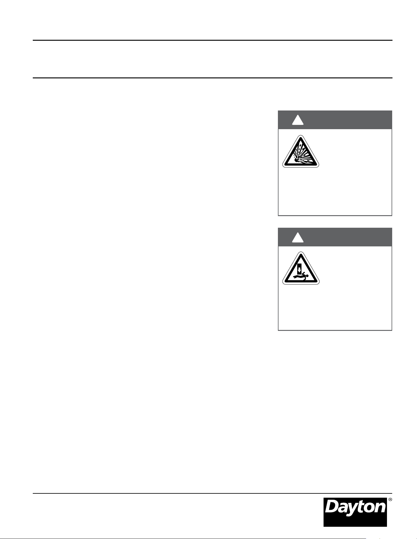
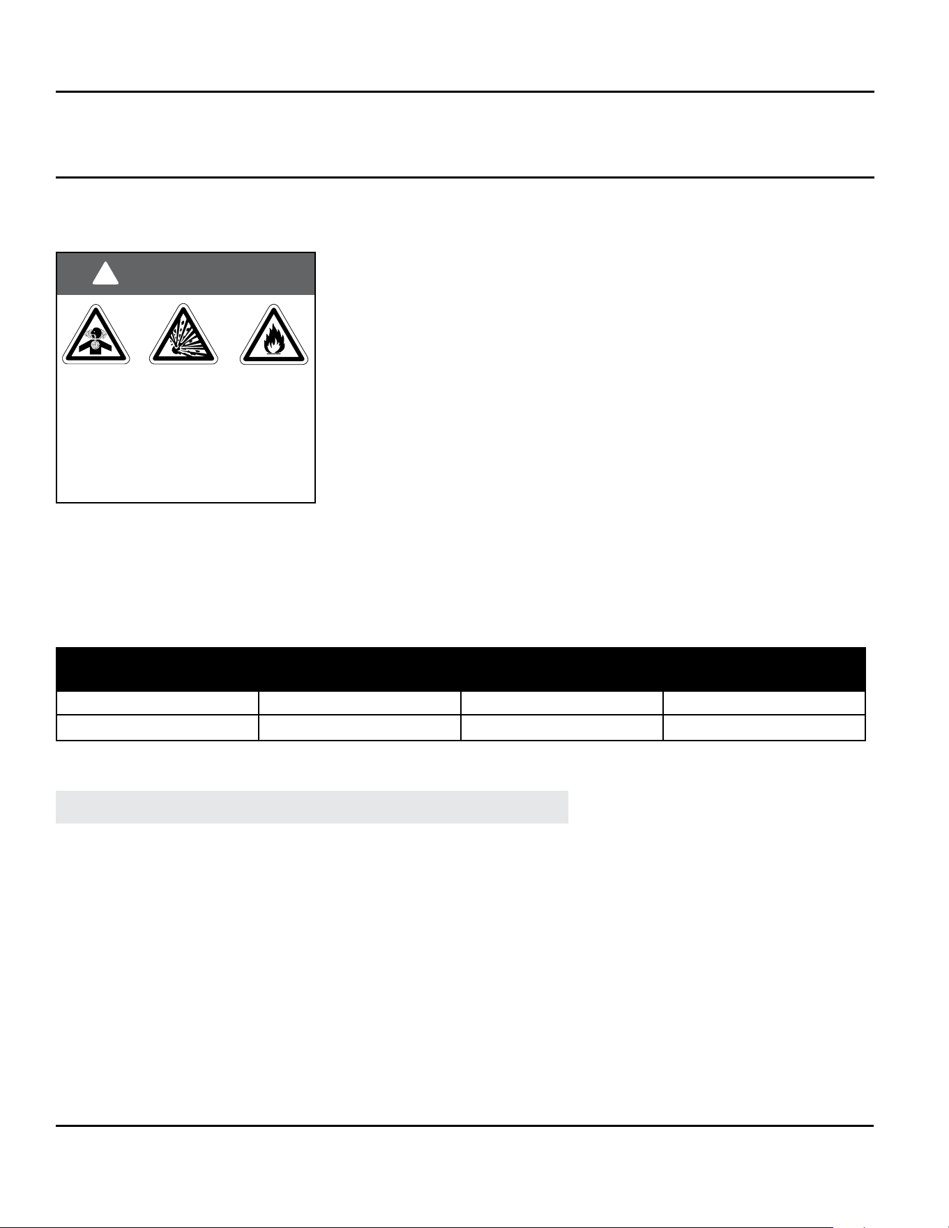
Applications
This is not an explosion-proof heater.
No heater may be used in a Class 1
or Class 2 Explosive Environment.
Consult the local re marshal, re
insurance carrier and other authorities
for approval if the proposed installation
is in question.
Do not use this heater
in the home, sleeping
quarters, attached
garages, etc.
Warning indicates a potentially
hazardous situation which, if not
avoided, could result in death or injury.
Caution indicates a potentially
hazardous situation which, if not
avoided, could result in minor or
moderate injury.
Notice indicates a potentially hazardous
situation which, if not avoided, could
result in property damage.
Not for residential use!
Commercial and Industrial
This tube heater is designed and
certied for use in industrial and
commercial buildings such as,
warehouses, manufacturing plants,
aircraft hangars, and vehicle
maintenance shops.
SAFETY
California Proposition 65
This product can expose you to chemicals
including lead and carbon monoxide,
which are known to the State of California
to cause birth defects or other reproductive
harm.
For more information, go to
www.P65Warnings.ca.gov.
WARNING
!
!
Dayton Installation, Operation, Maintenance, and Parts Manual
Models 7D837A thru 7D849A, 7D851A, 7AR79 thru 7AR88
5
Public Garages:
The installation of this heater in public
garages must conform with the
Standard for Parking Structures, ANSI/
NFPA 88A (latest edition), or the Code
for Motor Fuel Dispensing Facilities
and Repair Garages NFPA 30A (latest
edition) and must be at least 8 ft.
above the oor.
Aircraft Hangars:
The installation of this heater in aircraft
hangars must conform with the
Standard for Aircraft Hangars, ANSI/
NFPA 409 (latest edition). The heater
must be installed at least 10 ft. above
the upper wing surfaces and engine
enclosures of the highest aircraft which
might be stored in the hangar. In areas
adjoining the aircraft storage area, the
heaters must be installed at least 8 ft.
above the oor. The heaters must be
located in areas where they will not be
subject to damage by aircraft, cranes,
moveable scaffolding, or other objects.
High Altitude:
The installation of this tube heater
is approved, without modications,
for elevations up to 6,000 ft. above
MSL (sea level). Contact Dayton for
installations above these elevations.
Electrical:
The heater, when installed, must be
electrically grounded in accordance
with the National Electrical Code ANSI/
NFPA 70 (latest edition). Under no
circumstances is either the electrical
supply line or gas supply line to provide
any assistance in the suspension of the
heater.
Venting:
Venting must be installed in
accordance with the requirements set
forth in this manual and with the
NFPA 54/ANSI Z223.1 National Fuel
Gas Code (latest edition).
Standards, Certifications, and Government Regulations
The installation of this tube heater must comply with all applicable local, state,
and national specications, regulations, and building codes (contact the local
building inspector and/or re marshal for guidance) before installing the heater
system.
In the absence of local codes, the installation must conform to the latest edition
of the National Fuel Code ANSI Z223.1 (NFPA 54).
Refer to the following Standards and codes for application specic guidelines:
This unit complies with or is certied
by one or more of the following
organizations or standards:
• CSA International (CSA).
• American National Standards (ANSI
Z83.20b).
• National Fuel Gas Code (NFPA 54/
ANSI Z223.1).
• Occupational Safety and Health Act
(OSHA).
Dayton Installation, Operation, Maintenance, and Parts Manual
Dayton Tube Heaters
®
7D837A thru 7D849A, 7D851A, 7AR79 thru 7AR88
6
Fire Hazard. Always
maintain published
clearances to
combustibles. Failure
to comply with the
stated clearances to combustibles
could result in personal injury, death,
and/or property damage.
This heater should be
installed so that the
minimum clearances
to combustibles,
as marked on the
heater, will be maintained from
vehicles parked below. If vehicle
lifts are present, ensure that these
clearances will be maintained from
vehicles parked below. If vehicle
lifts are present, ensure that these
clearances will be maintained from
the highest raised vehicle.
WARNING
!
This is not an
explosion-proof
heater. Do not
store or use
ammable objects,
liquids, or vapor in the vicinity of
the heater. Where there is the
possibility of exposure to ammable
vapors or highly combustible
materials, consult the local re
marshal, re insurance carrier, and
other authorities for approval of the
proposed installation.
WARNING
!
WARNING
!
Clearances to Combustibles
For maximum safety, the building
must be evaluated for hazards before
installing this heating system. A critical
safety factor before installation is the
clearances to combustibles.
Clearance to combustibles is dened
as
the minimum distance that must be
maintained between the tube surface
or reector and combustible materials
.
It also pertains to the distance that
must be maintained from moving
objects (e.g. overhead doors, cranes,
vehicle lifts, etc.) around the tube
heater.
If you are unsure about the proposed
installation, consult your local re
marshal, re insurance carrier, or other
qualied authorities for the approval of
the proposed installation.
Safety Signs and Labels
It is important to provide warnings to
alert individuals to potential hazards
and safety actions. ANSI Z83.20 and
CSA 2.34, require you to post a sign
“specifying the maximum permissible
stacking height to maintain the
required published clearances from
the heater to combustibles” near the
heater’s thermostat or, in the absence
of such thermostats, in a conspicuous
location.
All safety labels must be maintained
on this appliance. Contact Grainger if
replacement labels are needed.
The following is a partial list of items to
maintain clearances from:
• Gas and electrical lines
• Combustible and explosive materials
• Chemical storage areas
• Areas of high chemical fume
concentrations
• Vehicle parking areas
• Vehicle lifts
• Hoists or cranes
• Storage areas with stacked materials
• Lighting
• Sprinkler heads
• Overhead doors and tracks
• Dirty, contaminated areas
• Plastics
Hazards
Dayton Installation, Operation, Maintenance, and Parts Manual
Models 7D837A thru 7D849A, 7D851A, 7AR79 thru 7AR88
7
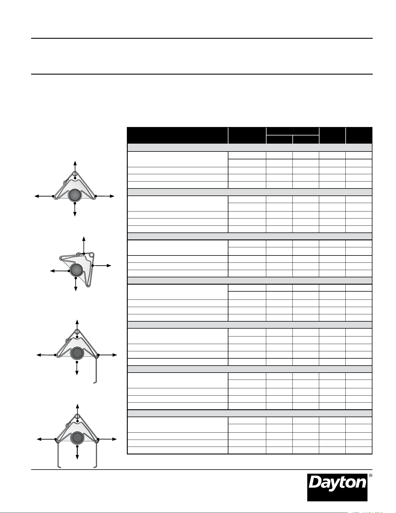
For the safe installation of this unit, the clearance to combustibles data below (Figure 1.1) contains clearances that must be
maintained. Check the heater’s rating plate to verify the minimum clearance to combustibles and gas type for your model heater.
Minimum end clearance for all models is 12 inches. *Heaters mounted on an angle between 0° and
45° must maintain clearances posted for both 0° and 45° mounting angles, whichever is greater.
0° Mounting
Angle
Top
Side
Side
Below
45° Mounting
Angle
Top
Front
Behind
Below
0° w/ 1 Side
Shield
Top
Front
Behind
Below
0° W/ 2 Side
Shields
Top
Side
Side
Below
Clearances to Combustibles
Figure 1.1 • Clearances to
Combustibles Data
Model No.
Mounting
Angle *
Side
Top BelowFront Behind
Dayton - 5VD67A, 5VD68A (20’ min. to 40’ max.)
50,000 BTU/H [N, P]
7D - 837A,838A
0° 9 9 6 47
45° 39 8 10 47
0° w/ 1 side shield 0° 29 8 6 47
0° w/ 2 side shields 0° 9 9 6 47
20 ft. from burner 0° 7 7 6 30
Dayton - 5VD69A, 5VD70A (20’ min. to 40’ max.)
75,000 BTU/H [N, P]
7D - 839A,840A
0° 9 9 6 60
45° 39 8 10 60
0° w/ 1 side shield 0° 29 8 6 60
0° w/ 2 side shields 0° 9 9 6 60
20 ft. from burner 0° 7 7 6 30
Dayton - 5VD71A, 5VD72A, 5VD73A, 5VD74A (30’ min. to 40’ max.)
100,000 BTU/H [N, P]
7D - 841A,842A,843A,844A
0° 14 14 6 66
45° 39 8 10 66
0° w/ 1 side shield 0° 29 8 6 66
0° w/ 2 side shields 0° 16 16 6 66
20 ft. from burner 0° 7 7 6 30
Dayton - 5VD75A, 5VD76A (40’ min. to 60’ max.)
125,000 BTU/H [N, P]
7D - 845A,846A
0° 20 20 6 76
45° 58 8 10 76
0° w/ 1 side shield 0° 42 8 6 76
0° w/ 2 side shields 0° 20 20 6 76
20 ft. from burner 0° 7 11 6 30
Dayton - 5VD77A, 5VD78A, 5VD79A, 5VD80A, 5EAJ0, 5EAJ1 (40’ min. to 60’ max.)
150,000 BTU/H [N, P]
7D-847A,848A,849A,851A, 7AR-79,80
0° 24 24 6 81
45° 58 8 10 81
0° w/ 1 side shield 0° 42 8 6 81
0° w/ 2 side shields 0° 23 23 6 81
20 ft. from burner 0° 11 11 6 44
Dayton - 5EAJ2, 5EAH3, 5EAH6, 5EAH7 (50’ min. to 60’ max.)
175,000 BTU/H [N, P]
7AR - 81, 82, 83, 84
0° 34 34 6 92
45° 63 8 10 92
0° w/ 1 side shield 0° 50 8 6 92
0° w/ 2 side shields 0° 30 30 6 92
20 ft. from burner 0° 11 11 6 44
Dayton - 5EAH4, 5EAH5, 5EAH8, 5EAH9 (50’ min. to 60’ max.)
200,000 BTU/H [N, P]
7AR - 85, 86, 87, 88
0° 41 41 6 94
45° 63 8 10 94
0° w/ 1 side shield 0° 54 8 6 94
0° w/ 2 side shields 0° 30 30 6 94
20 ft. from burner 0° 11 11 6 44
Dayton Installation, Operation, Maintenance, and Parts Manual
Dayton Tube Heaters
®
7D837A thru 7D849A, 7D851A, 7AR79 thru 7AR88
8
INSTALLATION
Design Considerations and Prechecks
Placement of infrared tube heaters
is inuenced by many factors. Aside
from safety factors, considerations
such as the number of elbows that
are allowed, maximum vent lengths,
ducting of combustion air, and
combining vents are a few examples.
This manual, along with national, state,
• Has the building’s heat loss been
evaluated?
• Does the design meet the needs of
the space?
• Have all clearances to combustibles
situations been observed?
• Have recommended mounting
heights been observed?
• Is the supply (burner) end of the
heater located where more heat is
required?
• Is it best to offset the heaters and/
or rotate the reectors towards the
heat zone?
and local codes, addresses these issues.
It is critical that all guidelines and
instructions are followed.
To ensure a properly designed heating
system, a heating layout should be
developed for the correct placement
of the burner control box, radiant
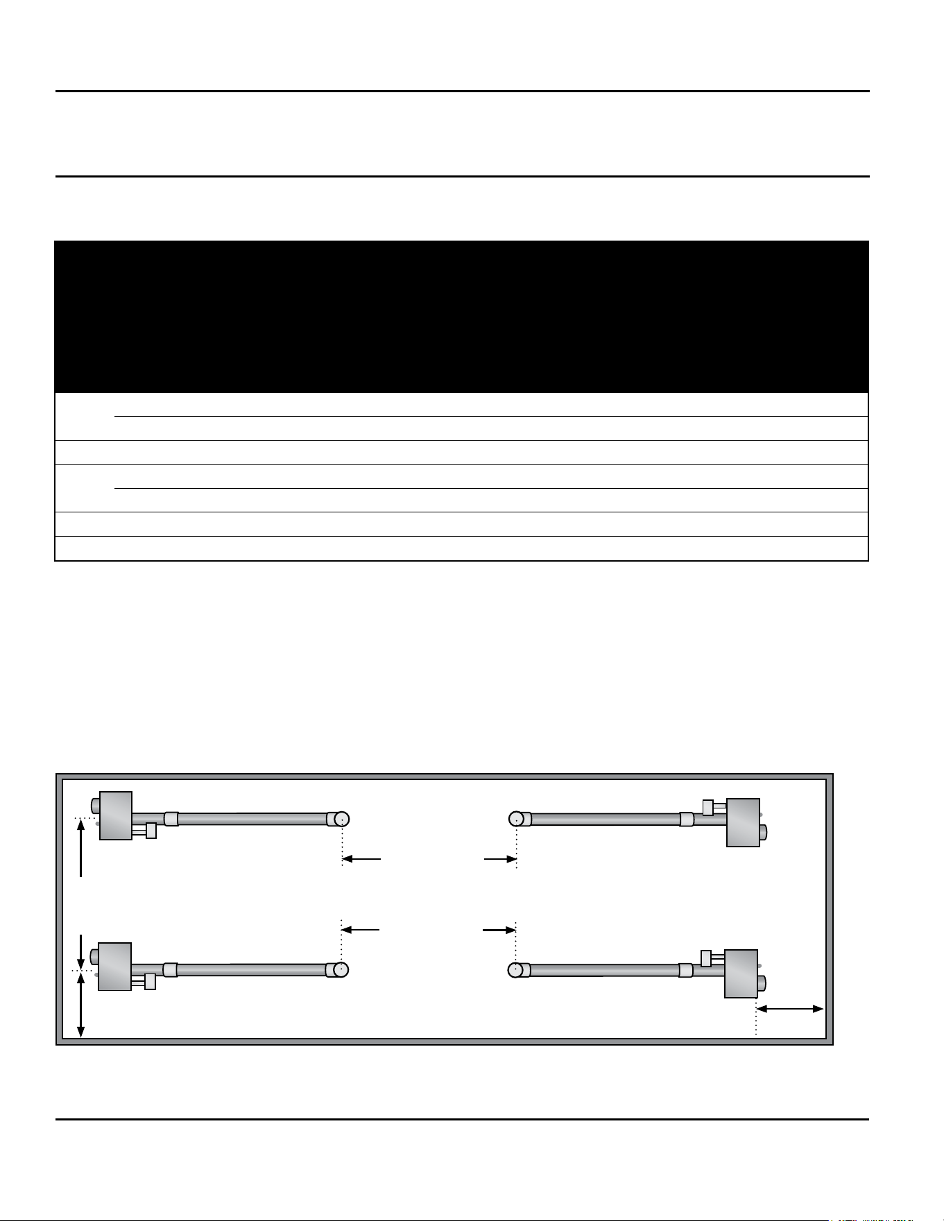
When designing an infrared radiant heating system, consider the following:
Model # BTU/h
Recommended
Mounting Heights
Distance
Between
Heaters
Distance
Between
Heater Rows
Maximum
Distance Between
Heater and Wall
7D837A-7D838A
50,000 9’ to 14’ 10’ to 20’ 20’ to 40’ 16’
7D839A-7D840A
75,000 11’ to 18’ 20’ to 30’ 30’ to 50’ 20’
7D841A-7D844A
100,000 13’ to 23’ 20’ to 30’ 30’ to 50’ 20’
7D845A-7D846A
125,000 14’ to 25’ 20’ to 30’ 30’ to 50’ 25’
7D847A-7D851A,
7AR79-7AR80
150,000 15’ to 35’ 30’ to 40’ 40’ to 60’ 25’
7AR81-7AR84
175,000 17’ to 35’ 30’ to 40’ 40’ to 60’ 30’
7AR85-7AR88
200,000 18’ to 40’ 30’ to 40’ 40’ to 60’ 30’
Heater Installation Chart
tubing, venting, and combustion air
intake ducts. Inspect and evaluate the
mounting conditions, vent locations,
gas supply, and electrical wiring.
Refer to the chart below for the
recommended distances for the model
being installed.
• Are protective guards, side shields,
‘U’ or ‘L’ reector covers needed?
• Does the heater require outside fresh
air for combustion?
• Is the environment harsh or
contaminated (requiring outside air
for combustion)?
• Are chemicals or vapor a
concern (requiring outside air for
combustion)?
NOTE: The effective infrared surface
temperature of a person or object may
be diminished with wind above 5 mph.
The use of adequate wind barrier(s)
may be required.
NOTE: When heated, materials high in
hydrocarbons (solvents, paint thinner,
mineral spirits, formaldehydes, etc.)
can evaporate. This may result in
odors or fumes being emitted into the
environment. To correct this problem,
clean the area and/or introduce
additional ventilation.
Heaters installed and serviced in
accordance with the installation
manual do not emit odors into the
environment. See notice on page 30
additional information.
Dayton Installation, Operation, Maintenance, and Parts Manual
Models 7D837A thru 7D849A, 7D851A, 7AR79 thru 7AR88
9
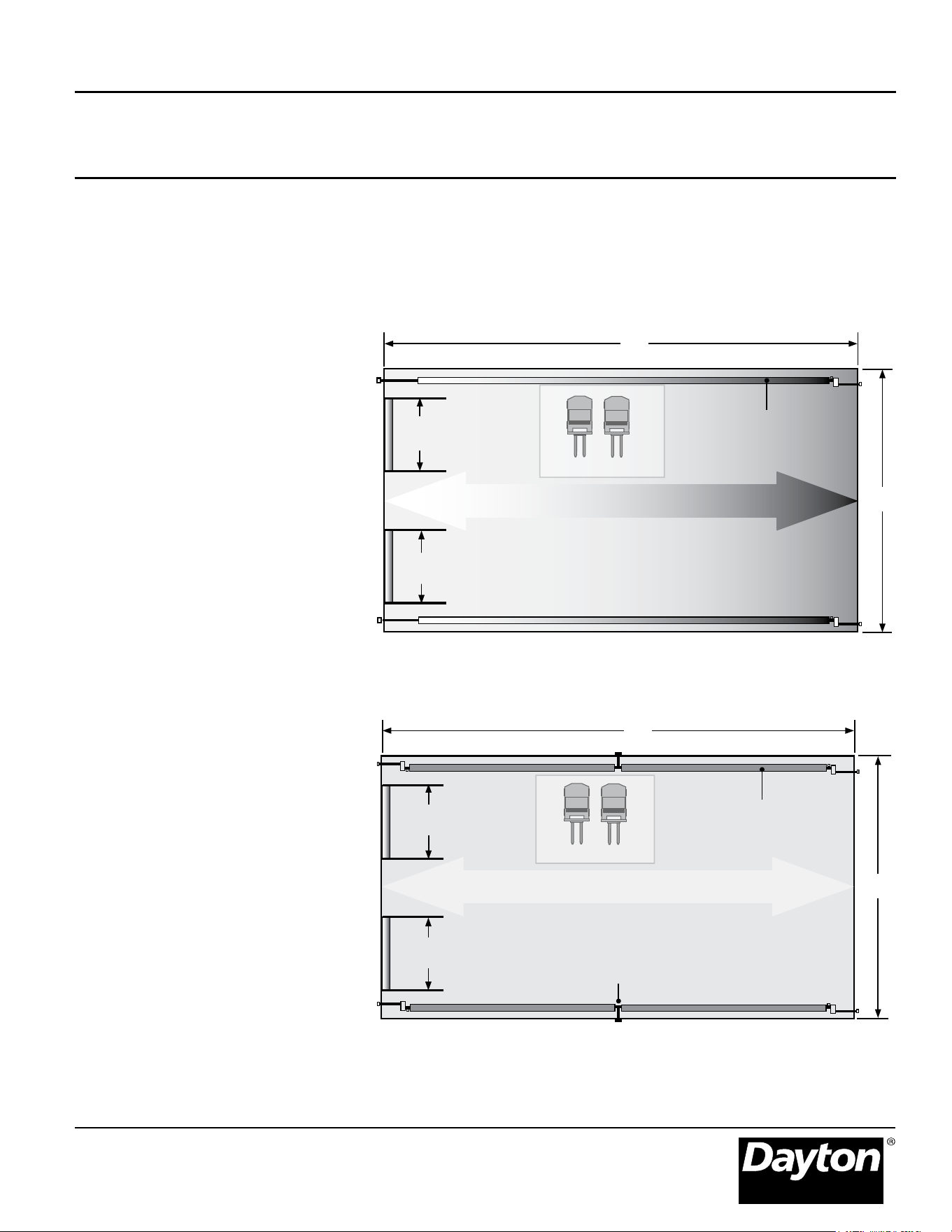
A tube heater system is being installed in 70’ (L) x 40’ (W) space with 12’ ceilings. Two overhead doors are located at one
end and an equipment storage area exists on one side. The calculated heat load is 300,000 BTU/h.
Design Scenario
Figure 2.1 • Poor Design
• Two burners (150,000 BTU/h each)
are placed at one end, opposite the
area of highest demand (overhead
doors).
• Recommended mounting heights
are not observed.
• Produces an uneven heat
distribution.
Figure 2.2 • Good Design
• Four burners (75,000 BTU/h each)
are placed in each corner. Burner
(hotter) ends direct heat to areas of
highest head demand.
• Recommended mounting heights
observed.
• Distributes heat more evenly.
Doors and
Tracks
Doors and
Tracks
Equipment storage
Better Heat Distribution
Sidewall Vent (2 total)
40’
70’
Gas Supply
20’ - 75,000 BTU
(4 total)
Good Design
Doors and
Tracks
Too Cold
Too Hot
Equipment storage
40’
60’ - 150,000 BTU
(2 total)
Doors and
Tracks
70’
Gas Supply
Poor Design
Dayton Installation, Operation, Maintenance, and Parts Manual
Dayton Tube Heaters
®
7D837A thru 7D849A, 7D851A, 7AR79 thru 7AR88
10
Recommended Mounting Heights
NOTE: Factory recommended
mounting heights are listed as a
guideline. If infrared heaters are
mounted too low or too high, they
may result in heat discomfort or lack of
heat. It is generally recommended to
Model
BTU Range
Recommended
Mounting Heights
Coverage Straight
Cong. (LxW)
Coverage U-Tube
Cong. (LxW)
Distance Between
Heater Rows (Ft.)
Dim. A
Distance Between
Heater Rows (Ft.)
Dim. B
Max. Distance Be-
tween Heaters and
Wall (Ft.)
Dim C
20 ft.
50 MBH 10’ - 16’ 20’ x 12’ 12’ x 12’ 10’ - 20’ 20’ - 40’ 16’
75 MBH 12’ - 20’ 22’ x 15’ 12’ x 12’ 20’ - 30’ 30’ - 50’ 18’
30 ft. 100 MBH 13’ - 20’ 33’ x 18’ N/A 20’ - 30’ 30’ - 50’ 20’
40 ft.
100-125 MBH 13’ - 25’ 44’ x 21’ 23’ x 17’ 20’ - 30’ 30’ - 50’ 20’
150 MBH 16’ - 30’ 45’ x 26’ 24’ x 20’ 30’ - 40’ 40’ - 60’ 25’
50 ft.
150-200 MBH 16’ - 30’ 56’ x 30’ N/A 30’ - 40’ 40’ - 60’ 25’
60 ft.
150-200 MBH 17’ - 40’ 67’ x 34’ 34’ x 26’ 30’ - 40’ 40’ - 60’ 25’
Dimension C
Maximum
distance
between
heater
and wall
Dimension A
Dimension B
Distance between
heater rows
Dimension C
Maximum distance between heater and wall
Dimension A
observe the recommended mounting
heights to optimize comfort conditions.
However, certain applications such
as spot heating, freeze protection,
outdoor patio heating, or very high
ceilings may result in the heaters
being mounted outside of the factory
recommended mounting heights.
Clearances to combustibles must
always be maintained.
Figure 2.3 • Recommended Mounting Heights and Distances - see chart above for dimensions.
Dayton Installation, Operation, Maintenance, and Parts Manual
Models 7D837A thru 7D849A, 7D851A, 7AR79 thru 7AR88
11
Hanger Placement and Suspension
Improper suspension
of the heater may
result in collapse
and being crushed.
Always suspend the appliance from
a permanent part of the building
structure that can support the total
weight and force of the heater.
WARNING
!
Failure to maintain
the published
clearances to
combustibles may
result in re and/or explosion,
property damage, serious injury, or
death. Always maintain clearances
and post signs where needed.
Suspension of the heater must
conform to applicable codes
referenced in the Safety section and
these instructions.
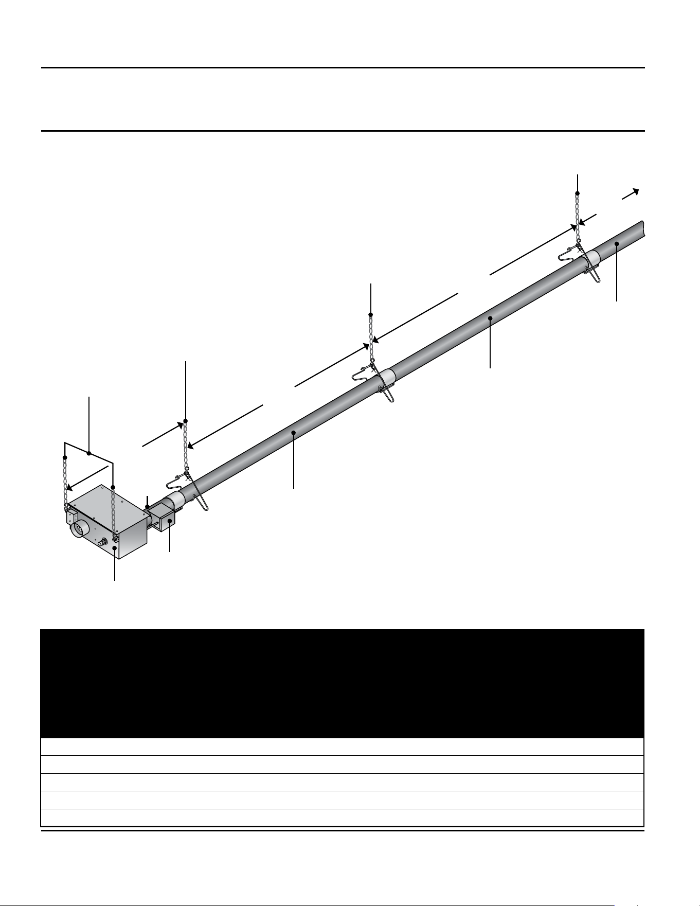
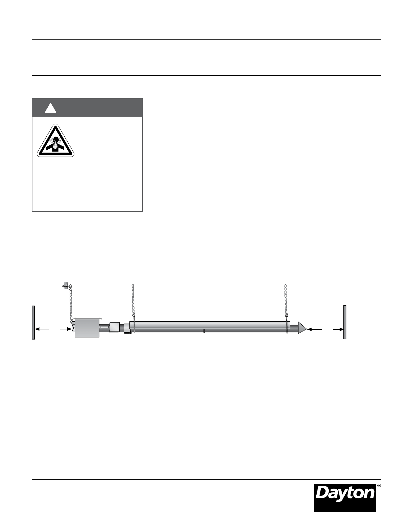
1. Lay radiant tubing out in the
following order. Position tubes in
their approximate locations. Figure
2.4.
• 10 ft. primary combustion
chamber.
• Radiant emitter tubes.
IMPORTANT! 150 MBH models must
use the 10 ft. titanium alloy treated
combustion chamber as the rst tube
connected to the burner control box.
The combustion chamber has an
orange identication sticker located on
the swaged end of the tube.
2. Mark locations for hanging points.
Figure 2.4 Chart.
NOTE: If the available hanging points
do not allow for the recommended
spacing (or if an alternative hanging
method is utilized) then additional
hangers may be necessary.
• The spacing between the burner
control box mounting brackets
and the rst hanger should be
approximately 2’-4”.
• The space between the rst two
hangers placed on the rst tube
should be approximately 8’-10”.
• The space between hangers
thereafter, one per tube, should be
approximately 9’-8”.
WARNING
!
16” Burner
Tube
Dayton Installation, Operation, Maintenance, and Parts Manual
Dayton Tube Heaters
®
7D837A thru 7D849A, 7D851A, 7AR79 thru 7AR88
12
10 ft. Primary Combustion Chamber
Radiant Emitter Tube
2’-4”
8’-10”
9’-8”
9’-8”
Burner Control Box
Radiant Emitter
Tube(s)
Hanging
Point
Burner Control Box
Hanging Points
Hanging
Point
Hanging Point
Igniter/Sensor Box
Hanger Placement and Suspension
Figure 2.4 • Heater Suspension Layout
Heater Mounting Requirements and Weights
NOTE: A sticker identifying the
combustion chamber(s) is located on
the swaged end of the tube(s).
Model
Dimension
Straight Config.
Hanging Points
Control Box
Hanging Points
Shipping Weight
Chain Set Qty.
Straight Config.
Chain Set Qty.
U-Tube Config.
Optional Brass
Knuckles (P/N:
5VD54)
Optional Single
Mount Bracket
(P/N: 5VD85)
U Config. Only.
20 ft. 21’-8” 3 2 120 lbs. 5 6 3 2
30 ft. 31’-4” 4 2 160 lbs. 6 N/A 4 N/A
40 ft. 41’-0” 5 2 190 lbs. 7 8 5 3
50 ft. 50’-8” 6 2 235 lbs. 8 N/A 6 N/A
60 ft. 60’-4” 7 2 265 lbs. 9 10 7 4
Dayton Installation, Operation, Maintenance, and Parts Manual
Models 7D837A thru 7D849A, 7D851A, 7AR79 thru 7AR88
13
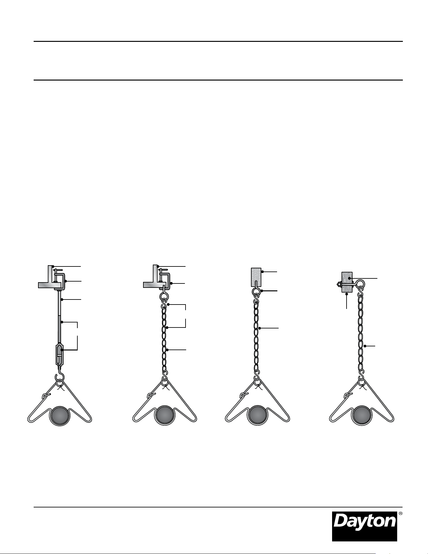
5. S-hook and
#1 double-loop
chain
3. Wood
Beam
3. Concrete
Beam
4. Beam Clamp
4. Screw Hook
4.
Screw
hook
with
locknut
and
washer
5. Threaded Rod
and Turnbuckle
6. Threaded Rod
6. Chain
3. I-Beam
4. Beam Clamp
6. Chain
6. Chain
3. I-Beam
Heater Placement and Suspension
Suspension of the heater must
conform to applicable codes
referenced in the Safety section and
these instructions.
3. Prepare the mounting surface. If
necessary, weld blocks, drill holes,
etc. Figure 2.5.
NOTE: The burner control box
and radiant tubes should be in
straight alignment and level.
Figure 2.5 • Mounting the Hangers
4. Fasten beam clamp, screw hook,
or other type of suspension anchor
to hanging point.
5. Attach and close S-hook and #1
double-loop chain to anchor.
Check that it is securely attached.
NOTE: Threaded rod and
turnbuckles may be used.
6. Attach hangers to chains. Adjust
chain lengths until radiant
tubing is level and equal weight
distribution is achieved.
NOTE: Chains must be straight up
and down. Do not install chains at
an angle as this can result in tube
warpage or separation.
Dayton Installation, Operation, Maintenance, and Parts Manual
Dayton Tube Heaters
®
7D837A thru 7D849A, 7D851A, 7AR79 thru 7AR88
14
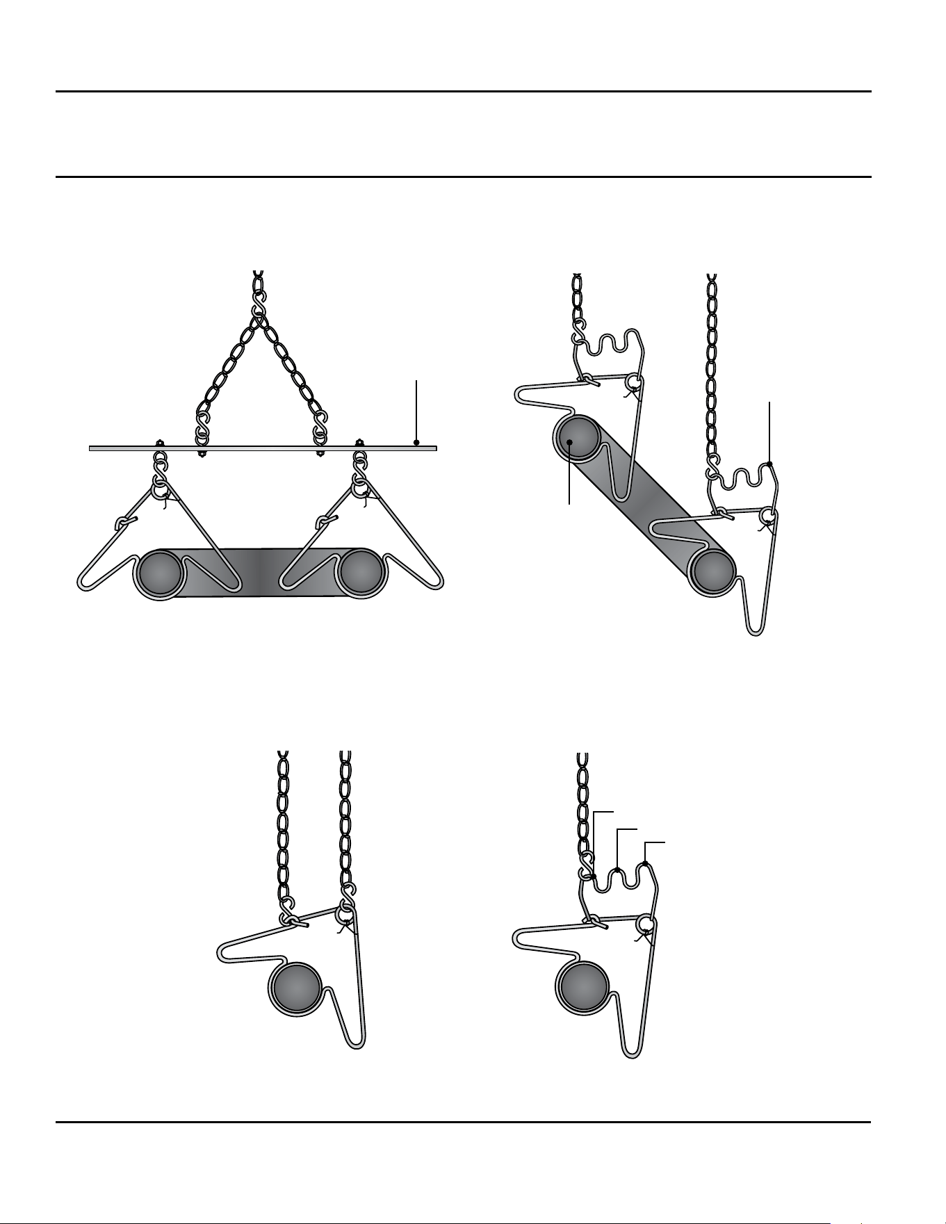
For 45° hanging angle, use two
S-hooks and two #1 double-loop chains.
For variety of hanging angles, use the Brass
Knuckle (P/N: 5VD54) tting with a #1
double-loop chain and S-hook.
45°
30°
15°
U-Tubes can be mounted at a
15°, 30° or 45° angle with two
suspension points using two Brass Knuckle
(P/N: 5VD54) ttings, #1 double-loop chains, and S-hooks.
U-Tubes can be mounted from a single suspension
point using a Single Mounting Bracket (P/N: 5VD85)
with ve S-hooks and #1 double-loop chains.
Figure 2.6 • U-Tube Hanger Mounting Options
Figure 2.7 • Angled Hanger Mounting Options
Exhaust
End
Single Mounting
Bracket
Brass Knuckle
Optional U-Bend or Elbow Accessory Configuration
Dayton Installation, Operation, Maintenance, and Parts Manual
Models 7D837A thru 7D849A, 7D851A, 7AR79 thru 7AR88
15
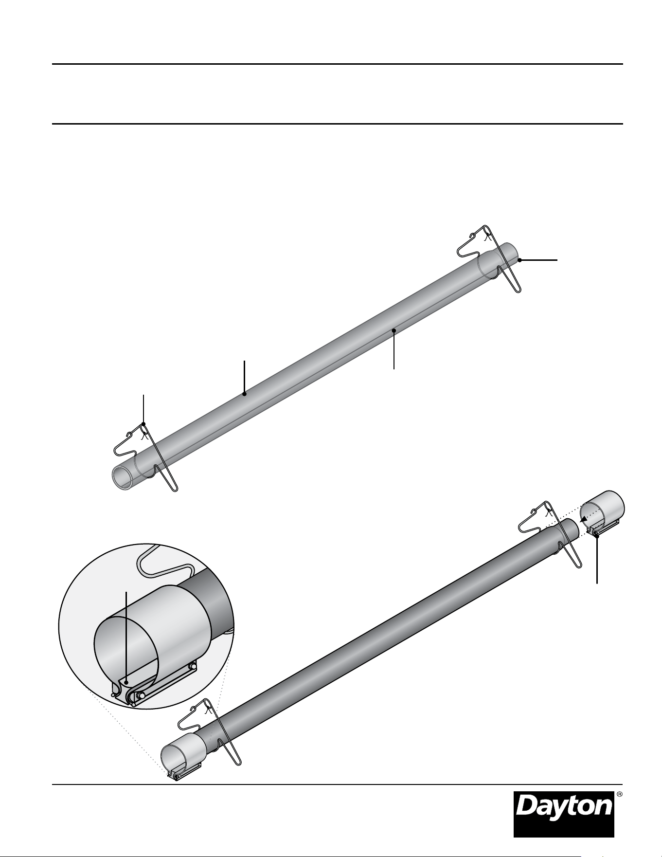
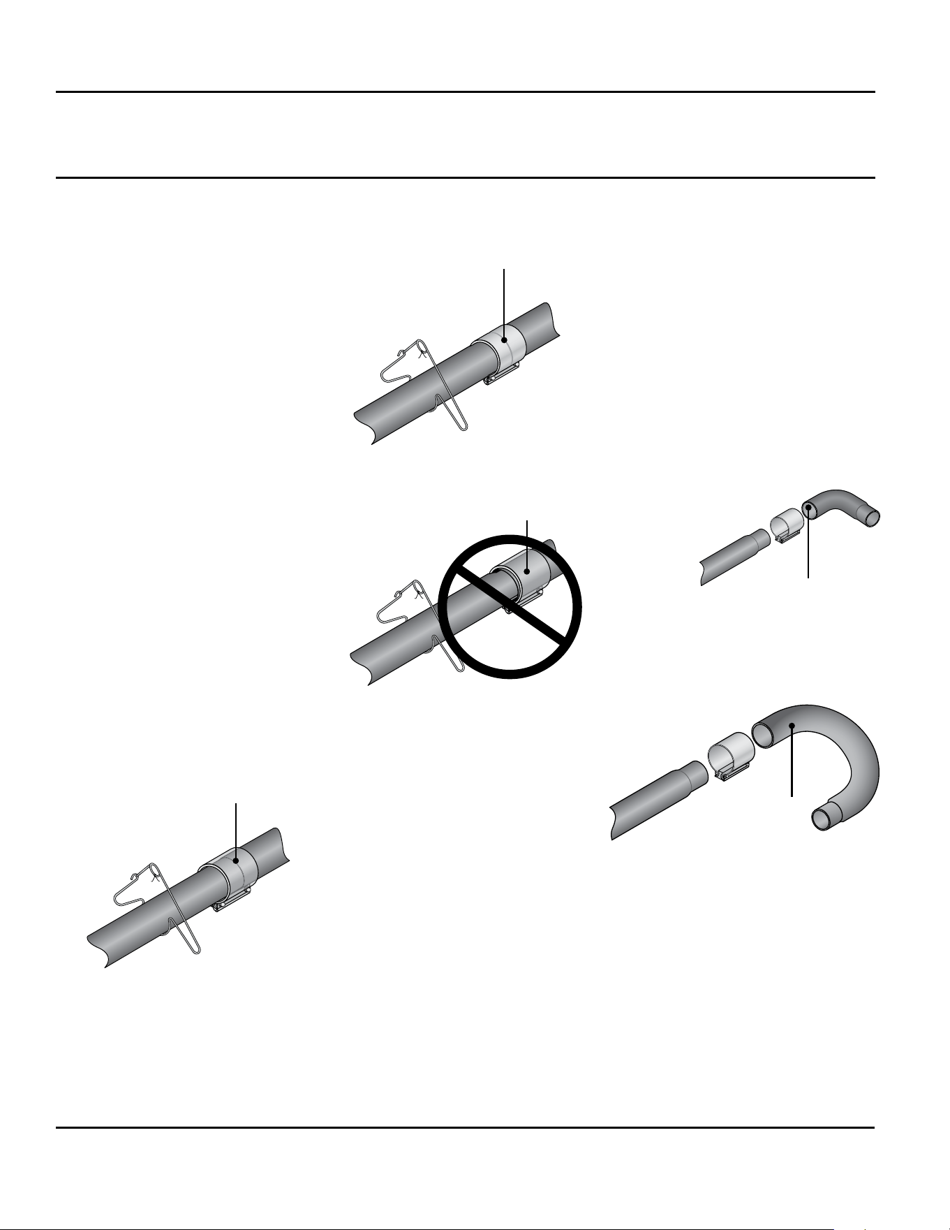
2. Slide tube clamps onto radiant tubes. Figure 2.9.
To install the radiant tubes:
1. Place tubes in hangers with the welded seam facing downward and the
swaged end of the tube towards the exhaust end of the heater system.
Figure 2.8.
Refer to Figure 2.21 on page 22 for tube installation sequence.
Figure 2.8 • Attach Hangers
Figure 2.9 • Attach Tube Clamps
Hanger
Welded seam
faces down
Swaged end
Tube clamp
Radiant tube
NOTE: If the tube clamp comes apart, the spacer
must be reassembled with the spacer’s concave
surface facing against the radiant tube surface.
Concave surface
Radiant Tube Assembly
Dayton Installation, Operation, Maintenance, and Parts Manual
Dayton Tube Heaters
®
7D837A thru 7D849A, 7D851A, 7AR79 thru 7AR88
16
3. Slip-t the radiant tube sections
together until tightly connected
(install swaged end of each tube
towards exhaust end). NOTE: If it
is difcult to mate the tubes, they
may be installed incorrectly.
4. Center tube clamps over the seams
where two radiant tube sections
connect. If necessary, rotate tube
clamps so they will not interfere
with the reector end caps during
expansion and contraction of the
heater while operating.
5. Tighten tube clamp bolts to secure.
When proper compression is
obtained (40-60 ft-lbs. torque), the
tube seam will create a visible mark
on the tube clamp.
NOTE: Excessive torque may
damage the tube clamp.
6. Determine the location of the
burner control box and note the
placement of the mounting chains.
Tubes t snuggly together and the tube
clamp is centered over the seam.
Tubes are not t snuggly together and
the tube clamp is not centered over the
seam.
The tube clamp is tight when proper
torque is achieved (normally when seam
becomes visible).
Correct Tube Connection
Incorrect Tube Connection
90 ° Elbow
Bend
180°
U-Bend
Figure 2.11 • Optional Tube
Connections
(P/N: 3F835)
(P/N: 3TZ71)
Radiant Tube Assembly
Optional U-Bend or Elbow
Accessory Configurations
A 180° U-Bend or 90° accessory tting
may be installed in the radiant tube
heater system.
Refer to chart on page 17 for minimum
distance requirements from the burner
control box.
When Installing a U-Bend or Elbow
Accessory Fitting:
•
The top clearance of an uncovered
(no reector) U-bend or elbow
accessory tting to combustibles is 18
inches.
• If operating the heater unvented,
separate the intake air to the heater
from its exhaust products a minimum
of 4 feet. Further separation may be
necessary. Combustion air may also
be supplied.
Figure 2.10 • Tube Connections
• A maximum of one 180° U-Bend or
two 90° elbows can be installed on a
heater.
• Omit one 36” section of turbulator
bafe. Refer to Bafe Assembly
section.
Dayton Installation, Operation, Maintenance, and Parts Manual
Models 7D837A thru 7D849A, 7D851A, 7AR79 thru 7AR88
17
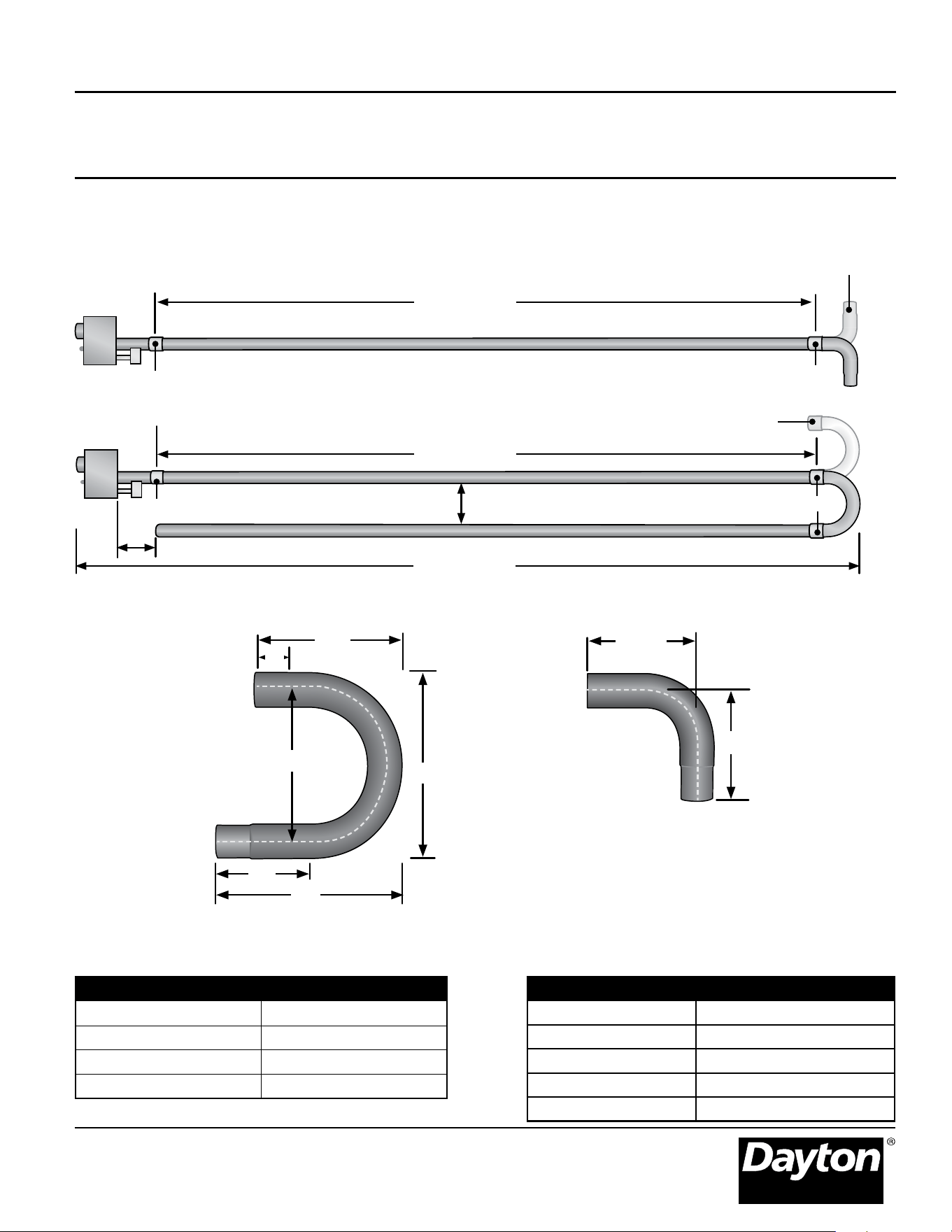
12.5”
Radiant Tube Assembly
Figure 2.12 • Elbow and U-Bend Clearances
Minimum Distance from Burner Control Box to
U-Bend or Elbow Accessory
Overall Dimensions for Heaters Configured
with U-Bend (P/N: 3F835)
Models Dimension A
50-100 MBH 10 ft.
125 MBH 15 ft.
150-175 MBH 20 ft.
200 MBH 25 ft.
Model Dimesion B
20 ft. 13’-0”
30 ft. N/A
40 ft. 22’-8”
50 ft. N/A
60 ft. 32’-4”
Figure 2.13 • U-Bend and Elbow Dimensions
P/N: 3F835
P/N: 3TZ71
16”
16”
6”
20”
10”
20”
12.5”
Dimension A
U-Bend can be set in both directions
12”
Elbow can be set
in both directions
Tube Clamp
Tube Clamp
Dimension A
Dimension B
8”
Tube Clamp
Tube Clamp
Dayton Installation, Operation, Maintenance, and Parts Manual
Dayton Tube Heaters
®
7D837A thru 7D849A, 7D851A, 7AR79 thru 7AR88
18
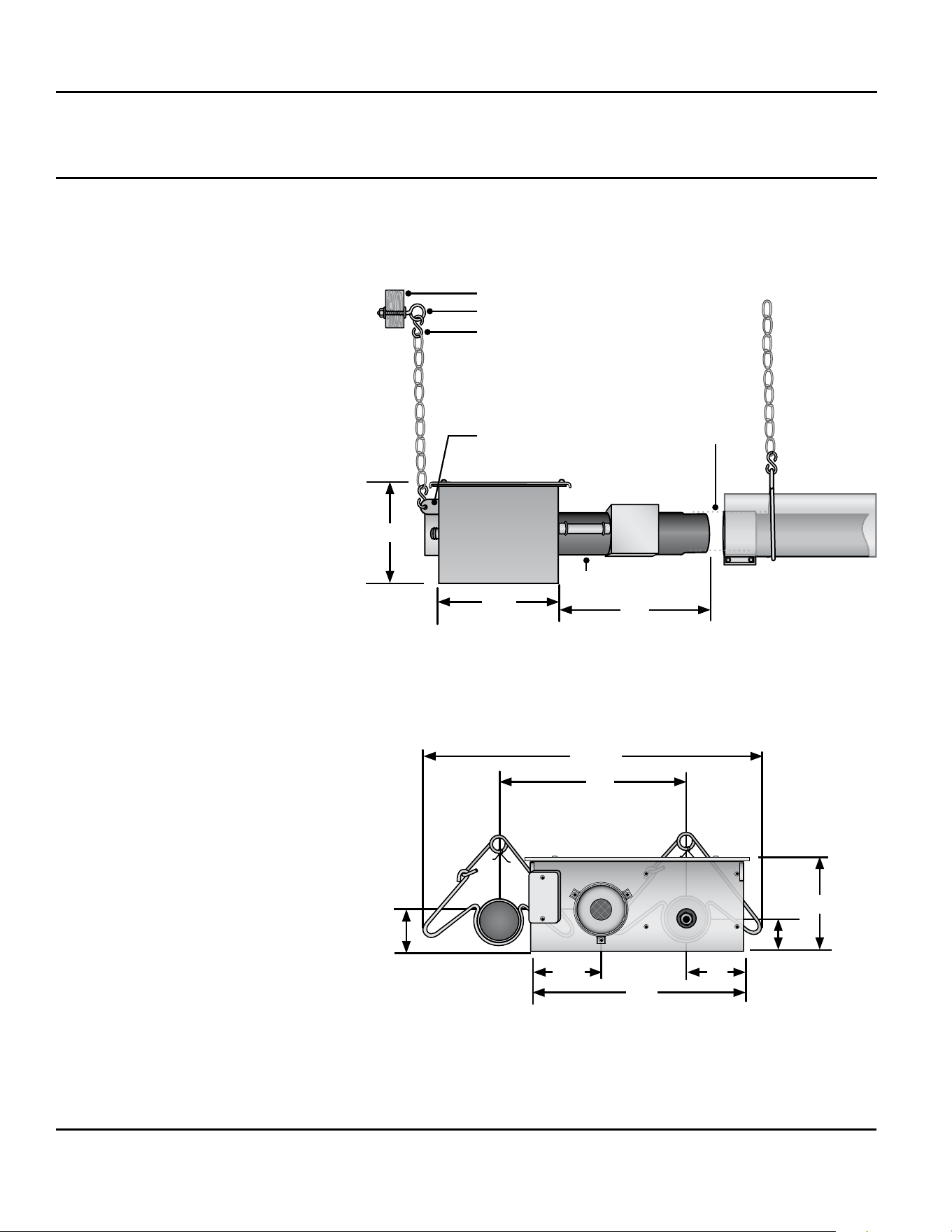
Suspending the burner control box
must be done in accordance with
applicable codes listed in the Safety
section and these instructions.
The burner control box must be in
straight alignment with the radiant
tubes and level.
1. Determine the mounting chain
locations for hanging the burner
control box.
2. Fasten beam clamp, screw hook or
other type of suspension anchor to
hanging point.
3. Attach and close S-hook and #1
double-loop chain to anchor.
Check that is securely connected.
4. Attach chain assemblies and
S-hooks to mounting brackets on
the burner control box. Adjust
chain lengths until level and in
straight alignment with the radiant
tubes. The burner sight glass will
be visible from the oor.
Figure 2.14 • Burner Control Box Assembly • Side View
Figure 2.15 • Burner Control Box with U-Bend • End View
Burner Control Box Suspension
29.6”
16”
5.5”
5”
18”
3.5”
3”
8.1”
1
2
3
4
Burner Sight Glass
(bottom side of the tube)
Burner Control Box tube is in
straight alignment with 10’
Primary Combustion Chamber
12”
16”
8.1”
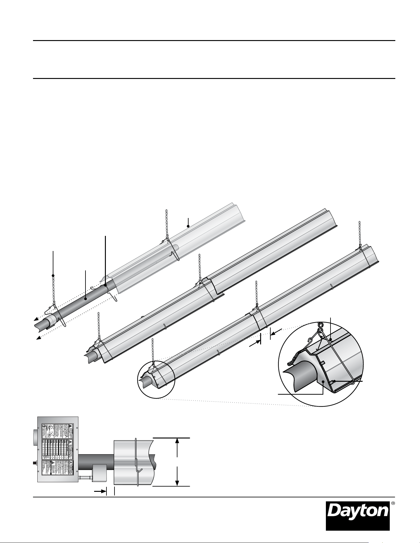
To install the reflectors:
1. Attach reector center supports
onto radiant tubes.
2. Slide each reector section through
the hangers and adjust the reector
tension spring into the V-groove
on the top of the reector.
The reectors should overlap
approximately 4”.
Figure 2.16 • Reflector Assembly
Reflector Assembly
3. To prevent the reectors from
shifting, secure the reector
sections together using sheet metal
screws except at the expansion
joint. Figure 2.21. NOTE: Installer
to provide sheet metal screws.
4. Attach reector end caps, with
polished side inward, to each end
of the reector run.
Reectors, and reector accessories,
direct infrared energy to the oor
level. The reector assembly depends
on the heater conguration, proximity
to combustibles and the space
surrounding the heater.
Before you begin assembly, determine
if the use of reector accessories are
necessary. Figure 2.18.
Reector
4”
Overlap
Reector Center
Support
Radiant
Tube
Hanger and
Chain
Reector End Cap
Reector Tension
Spring
Clips
Figure 2.17 • Width of Installed Reflector - Top View
13.75”
Dayton Installation, Operation, Maintenance, and Parts Manual
Models 7D837A thru 7D849A, 7D851A, 7AR79 thru 7AR88
19
1”
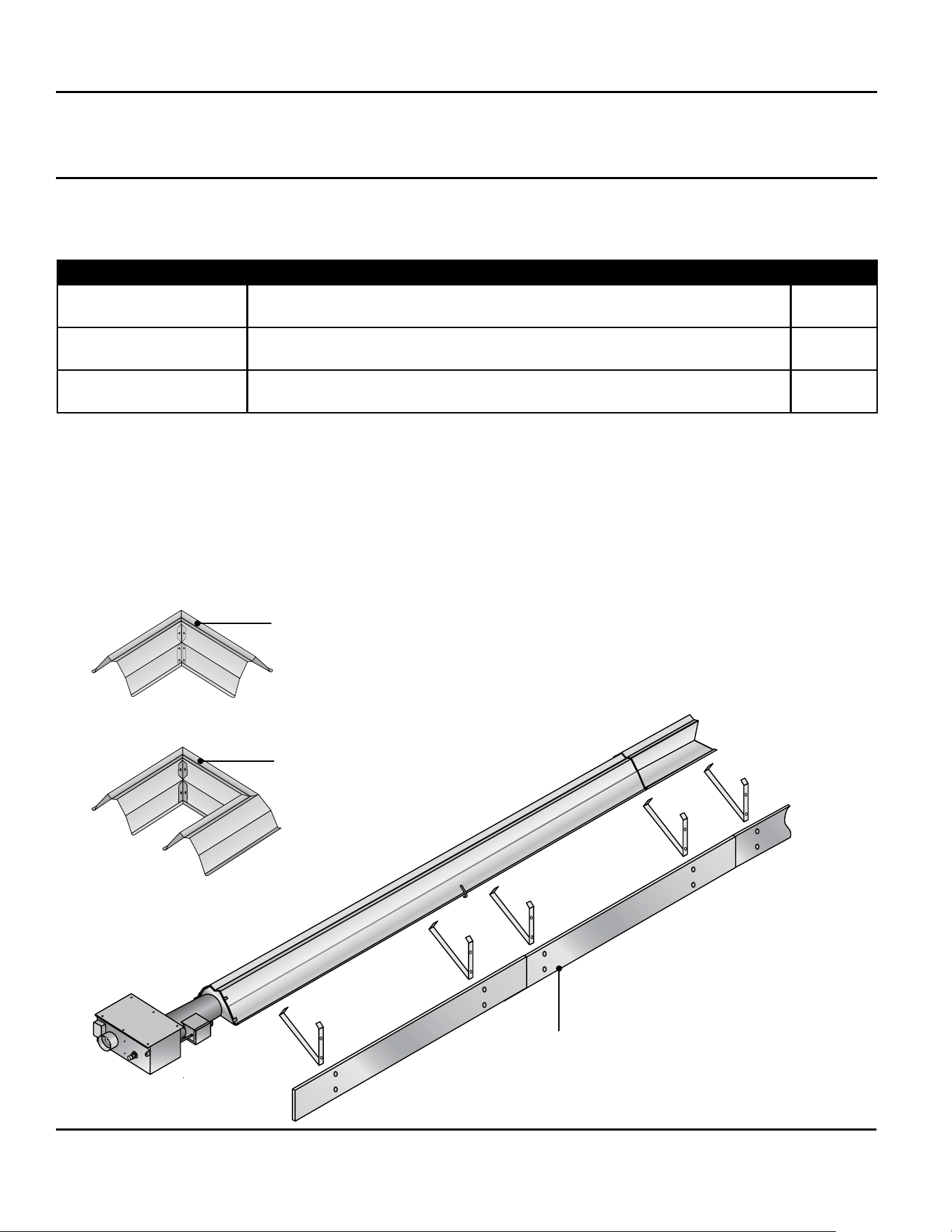
Figure 2.18 • Reflector Shield Accessories
Side shield extension (P/N: SSE)
Directs infrared rays downward, away
from sidewalls and combustibles.
Elbow reector (P/N: 5VD83)
Used over a 90° elbow radiant
tube.
U-shaped reector (P/N: 5VD84)
Used over a ‘U-shaped
radiant tube.
Reflector Assembly
Common Optional Accessories
Reector Accessories Description Part #
Elbow Reector* 90° bend, highly polished aluminum reector elbow. Designed to t atop one
elbow accessory tting.
5VD83
U-Reector* 180° bend, highly polished aluminum reector U-Bend. Designed to t atop
one U-Bend accessory tting.
5VD84
Side Shield Reector *^
Highly polished side shield extension used to direct infrared rays downward,
away from side walls and combustibles.
SSE
t
* Reectors cannot be rotated when used with this accessory.
^ Refer to the Clearances to Combustibles chart on page 7 for minimum distances to combustibles when side shield
extension(s) are used. extension(s) are used.
t Accessory is available through Grainger Sourcing.
Additional accessory options are available in the W.W. Grainger catalog.
Dayton Installation, Operation, Maintenance, and Parts Manual
Dayton Tube Heaters
®
7D837A thru 7D849A, 7D851A, 7AR79 thru 7AR88
20
Baffle Assembly and Placement
Figure 2.19 • Assembling the Baffles
Figure 2.20 • Inserting the Baffles
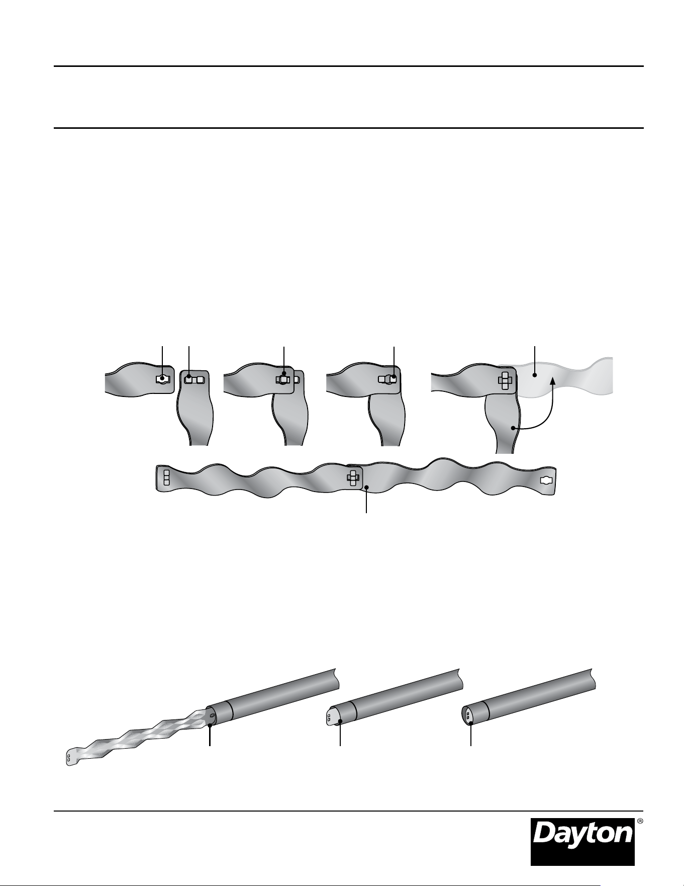
To insert the baffles:
1. Insert bafes with the keyhole end
rst.
2. Rotate bafe assembly so that it is in
the vertical position.
To assemble the baffles:
NOTE: Bafes may be inserted into the
tube while being assembled.
1. Determine the number of bafes
needed for your model number.
Remove one 36” bafe section if
heater is installed with an elbow or
U-Bend accessory.
2. Install the bafe tabs at a 90° angle
to the bafe keyhole.
Figure 2.19.
3. Insert one bafe tab into keyhole
and slide completely to one side
until both bafe tabs appear in the
keyhole.
4. Adjust the tabs to the center of the
keyhole and rotate the bafe 90° to
lock the bafe sections together.
5. Repeat this process with remaining
bafe sections to complete
assembly.
3. Slide bafe assembly into the last
radiant tube section, furthest from
burner control box.
NOTE: Bafe assemblies longer than
10’ will continue to be fed into next
tube section.
2
Bafe keyhole
Bafe tabs
3
4
Completed connection
IMPORTANT: Bafe assembly must be
ush with the end of the last tube
section and in the vertical position.
321
Dayton Installation, Operation, Maintenance, and Parts Manual
Models 7D837A thru 7D849A, 7D851A, 7AR79 thru 7AR88
21
Final Heater Assembly
Figure 2.21 • Secured Reflector Joints and Baffle Location
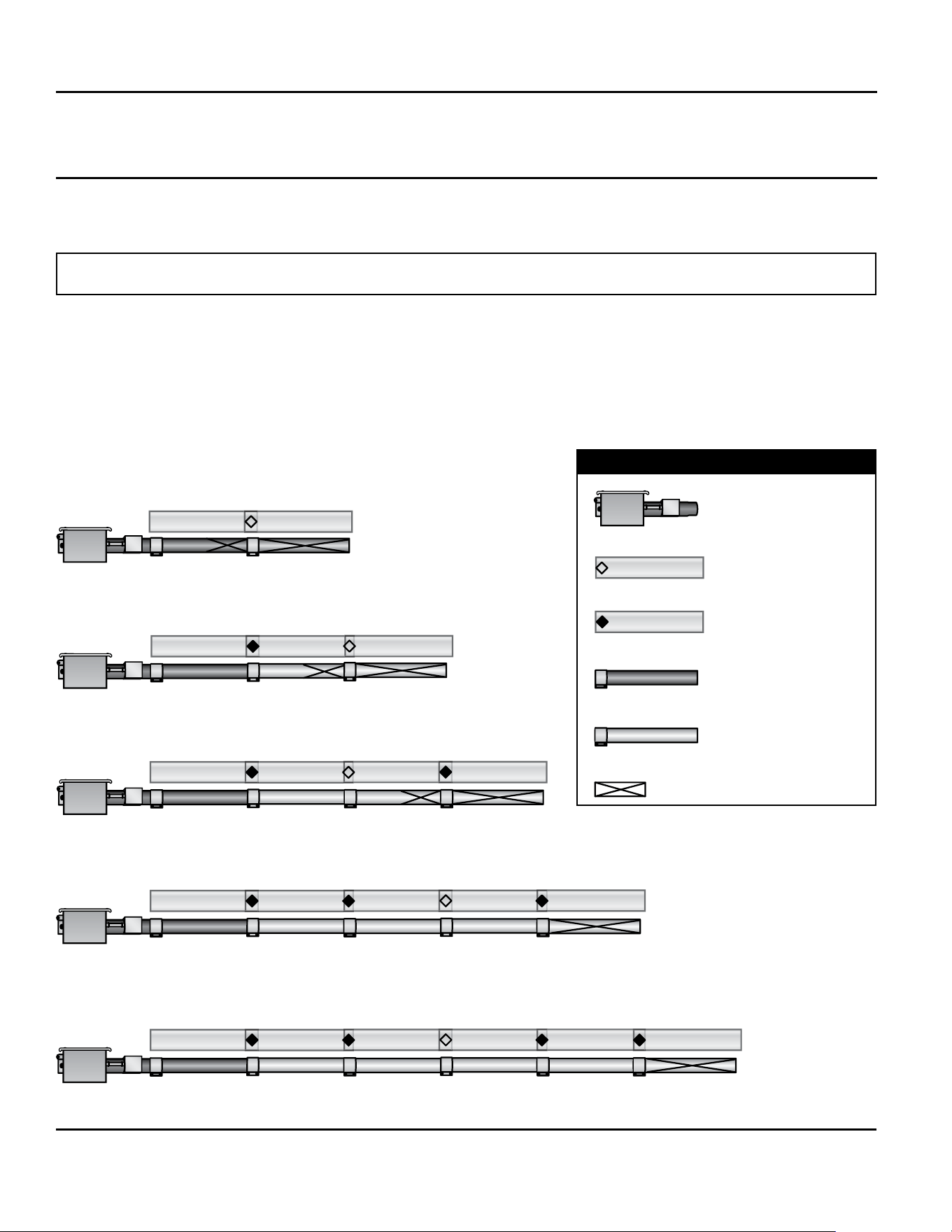
Different inputs and models utilize different bafe lengths. Remove all enclosed bafe sections from box and retain with
applicable heater. Reference shipping label for proper bafe size.
Each 36” bafe section must be assembled with other bafes and placed in the radiant tube section furthest from the
burner. Important: Omit one section of bafe if heater is congured with a U-Bend or Elbow accessory tting.
NOTICE
20 Foot
50 Foot
30 Foot
40 Foot
Burner Control Box
with 16” Burner Tube
Key
Expansion Joint on
Reectors
Secured Joint on
Reectors
Primary Combustion
Chamber Tube with
Clamp
Radiant Tube with
Clamp
Bafe Location
60 Foot
Dayton Installation, Operation, Maintenance, and Parts Manual
Dayton Tube Heaters
®
7D837A thru 7D849A, 7D851A, 7AR79 thru 7AR88
22
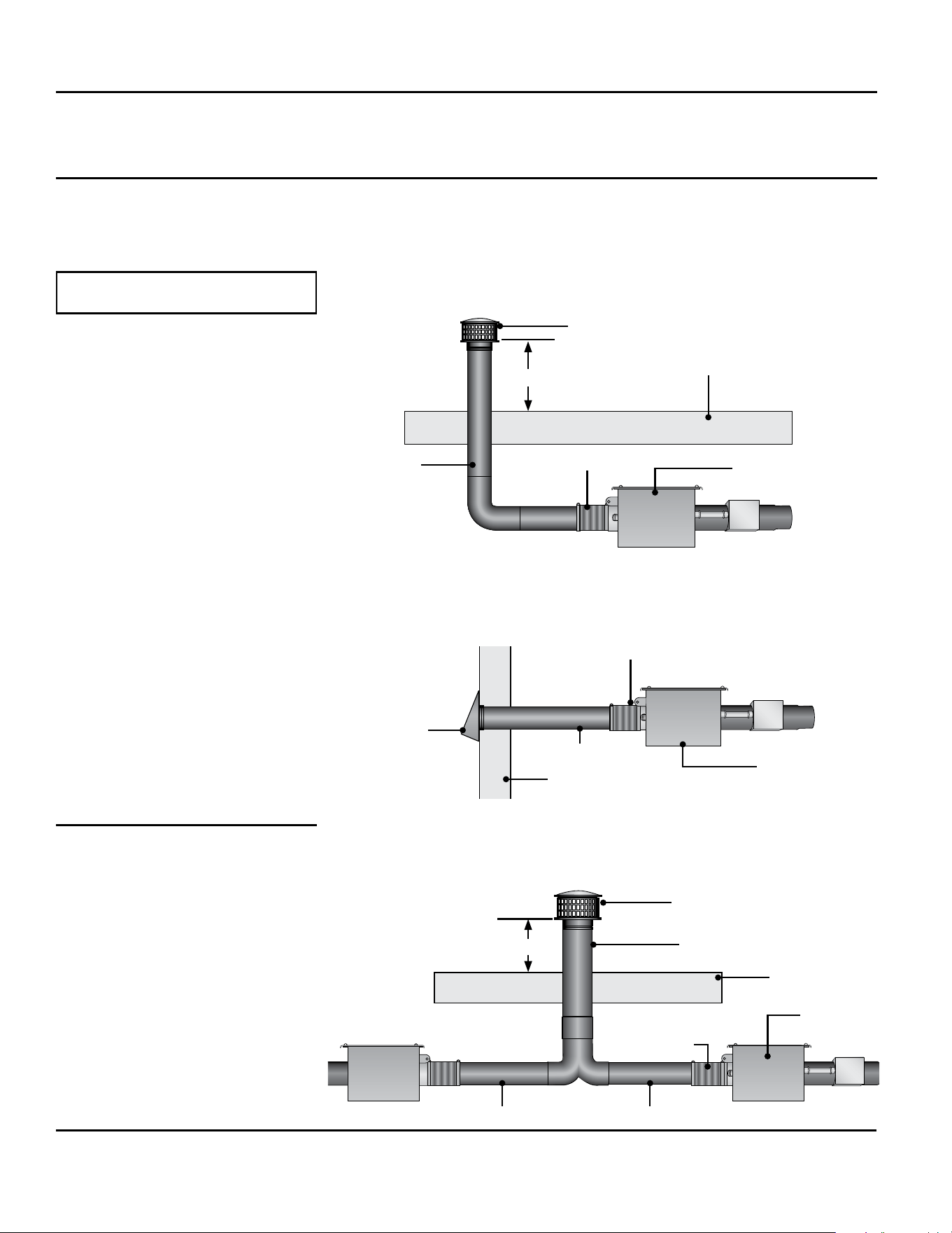
The heating system must be vented as
described here to properly direct ue
gases from the unit to the outside
atmosphere. The venting can terminate
vertically through the roof (up) or
horizontally through a sidewall
(sideways).
Follow these guidelines and all
applicable codes for all models prior to
installing the vent material. Local codes
may vary.
In the absence of local codes:
United States: Refer to NFPA 54/
ANSI Z223.1 (latest edition),
National Fuel Gas Code.
Canada: Refer to CAN/CGA B149.1
and B149.2 Installation Codes for
Gas Burning Appliances.
If the heater is replacing existing
equipment and using an existing vent
system, inspect the venting for proper
size and horizontal pitch as directed in
these instructions and the latest edition
of the National Fuel Gas Code, ANSI
Z223.1 (NFPA 54) or CSA B149.1
Installation Code. When an existing
Category I heater is removed or
replaced, the original venting system
may no longer be sized to properly vent
the attached appliances.
Determine that there is no blockage or
restriction, leakage, corrosion, or other
deciencies that can cause hazards. The
vent pipe should be corrosion-resistant
galvanized steel of a thickness that
meets the National Fuel Gas Code.
Minimum thickness for connectors
varies depending on the pipe diameter.
Never vent the heater with PVC or
plastic pipe.
Dayton Installation, Operation, Maintenance, and Parts Manual
Models 7D837A thru 7D849A, 7D851A, 7AR79 thru 7AR88
23
Venting
Replacing Existing Equipment
WARNING
!
!
WARNING
!
!
Gas-red heaters must
be vented. A built in
power exhauster is
provided. Additional
external power
exhausters are not
required or permitted.
Insufcient ventilation and/or
improperly sealed vents may release
gas into the building which could
result in health problems, carbon
monoxide poisoning, or death.
Improper venting may result in re,
explosion, injury, or death.
Do not vent this appliance into
another heater’s vents or through a
masonry chimney.
Do not use dampers in the heater
vent pipe.
Single wall vent pipe must not pass
through any unoccupied attic, inside
wall, concealed space, or oor.
Un-insulated single wall vent pipe
must not be used outdoors for
venting appliances in regions where
winter design temperature is below
freezing.
WARNING
!
!
If replacing an existing
heater, vents may
require re-sizing.
Improperly sized
venting systems can
result in vent gas
leakage or condensation. Refer to the
National Fuel Gas Code ANSI Z223.1
(NFPA 54) or CSA B149.1 - latest
edition. Failure to follow these
instructions can result in serious injury
or death.

The venting system may terminate
horizontally through a sidewall or
vertically through the roof, and may be
individually or commonly vented.
Conguration of the vent termination
determines the category type. All
model heaters must be installed in
accordance with the requirements of
this section, as well as the requirements
of its category determination, as
described in this manual. To determine
your applications category type, review
“Vertical Venting (Category I)” and
“Horizontal Venting (Category III)”
sections of this manual.
When possible, avoid venting through
an unconditioned space. Venting
through an unconditioned space
promotes condensation. When venting
through an unconditioned space is
unavoidable, or if the unit is installed in
an area that is prone to condensation,
insulate venting runs greater than 5 feet
to minimize the production of
condensation. Inspect for leakage prior
to insulating the venting and only use
insulation that is non-combustible with
a temperature rating of not less than
550°F. Install a tee tting at the low
point of the vent system and provide a
drip leg with a clean out cap as shown
in Figure 2.22.
When venting pipe passes through a
combustible interior wall or oor, a
metal thimble with a diameter 4 inches
greater than the vent pipe diameter
must be used. If there is 6 feet or more
of vent pipe prior to passing through
the combustible wall or oor, then the
metal thimble need only be 2 inches
greater than the vent pipe diameter. If a
metal thimble is not used, all clearances
to combustibles from the vent pipe
must be 6 inches. When permitted,
type B vent or Duravent PVP venting
may be used for the last section of vent
pipe to reduce the required clearances
to combustibles when passing through
a combustible wall or oor. When
using type B vent or Duravent PVP
venting, follow the manufacturer’s
recommended clearances to
combustibles. Any material used to
close or insulate the opening must be
non-combustible.
Dayton Installation, Operation, Maintenance, and Parts Manual
Dayton Tube Heaters
®
7D837A thru 7D849A, 7D851A, 7AR79 thru 7AR88
24
General Venting Requirements
All Model Requirements
• Exhaust vent pipe must be 4 inch
nominal size unless common venting.
For vent pipe sizes when common
venting, see pages 27-28.
• Use vent pipe material that is
corrosion-resistant galvanized steel of
a thickness that meets the National
Fuel Gas Code.
• Do not exceed a maximum vent
length of 20 feet.
• Maintain a minimum vent length of 3
feet.
• Maintain a minimum of 12 inches of
straight pipe from the ue outlet
before any directional changes are
made in the venting system.
• Have all vent pipe seams or
connectors sealed with high
temperature silicone sealant approved
for at least 550°F (eld supplied) and
fastened together with at least three
(3) corrosion resistant sheet metal
screws (eld supplied).
• Maintain a 6 inch clearance around all
single wall vent pipe from any
combustible materials. For double-
wall type B vent or Duravent PVP
venting, follow the vent
manufacturer’s clearances to
combustibles.
• The equivalent length for a 4 inch 90°
elbow is 5 feet.
• Avoid using more than two 90°
directional changes in the venting
system.
• Suspend and secure all horizontal
runs in a manner consistent with local
codes and in such a way that the vent
system is supported to prevent
sagging.
• Vent termination must maintain a
minimum distance of 6 feet from any
mechanical air supply inlet.
• The vent terminal must be installed to
prevent any blockage by snow and
protect building material from
degradation by ue gases.
• Consult NFPA ANSI Z223.1 Gas Vent
Termination criteria for vents that
terminate on a roof pitch that exceeds
9:12.
• Canada: Vents must terminate a
minimum of 3 feet from a window or
door that may be opened, and a
non-mechanical air supply inlet or
combustion air inlet into the building.
An appliance that operates with a
non-positive vent static pressure and
with a vent gas temperature that avoids
excessive condensate production in the
vent is said to be ‘Category I’. The
heater is considered a Category I
appliance if the venting system meets all
of the following criteria:
• The vent system terminates vertically
(up).
• The length of the horizontal portion
of the vent run is less than 75% of
the vertical rise length. (e.g.- If the
vertical vent height is 10 feet, the
horizontal run is less than 7 1/2 feet).
• The vent terminates a minimum of 5
feet above the vent connection on
the unit.
• Horizontal venting sections of the
vent pipe must be installed with an
upward slope from the appliance at a
pitch of 1/4 inch per foot.
For vertical vent termination, the
venting must comply with all parts of
this section, in addition to the
requirements of the general venting.
Category I (Vertical) venting is venting
at a non-positive pressure. An
appliance vented as a Category I is
considered a fan-assisted appliance
and the vent system does not have to
be ‘gas tight’. It is recommended that
the venting system is installed with a
tee, drip leg, and clean-out cap as
shown in Figure 2.22.
Dayton Installation, Operation, Maintenance, and Parts Manual
Models 7D837A thru 7D849A, 7D851A, 7AR79 thru 7AR88
25
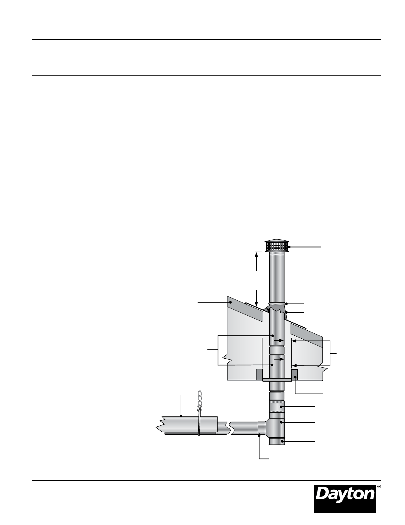
Vertical Venting (Category I)
Vent Locations and Clearances:
• Separate air intake duct from vent
pipe by a minimum of 4 feet by
placing vent pipes higher than
adjacent air intake ducts.
• Utilize a listed type B vent termination
cap.
• The vent terminal must extend a
minimum of 2 feet above the roof.
• Vent caps should be located a
minimum of 2 feet away from
adjoining structures.
Figure 2.22 • Rooftop Venting - Side View
All vertically vented heaters that are
Category I must be connected to a
chimney or vent complying with a
recognized standard, or lined masonry
(or concrete) chimney with a material
acceptable to the authority having
jurisdiction. Venting into an unlined
masonry chimney is not permitted.
Refer to the National Fuel Gas Code
and page 24 of this manual.
Use a listed vent terminal to reduce
down drafts and moisture in the vent.
Heater
#8 Sheet Metal Screws (eld supplied)
1 in. Minimum
Clearance -
Use Attic
Insulation Shield
(Field Supplied)
B to C Adapter
Clean Out Tee Fitting
Clean Out Cap
*Consult the NFPA ANSI Z223.1 Gas Vent Termination criteria if roof pitch exceeds 9:12
24 in.
Min*
Vent Cap
Roof
Adjustable Roof Flashing
Storm Collar
Double-Wall B Vent
Fire Stop Spacer
One continuous section of double-wall
B vent or Duravent PVP vent may be
used to pass through a combustible
wall or barrier, or the installer may
continue to use single-wall vent
provided a combustible wall thimble is
used which provides adequate
clearances to combustibles.
All horizontal Category III vents must
be terminated with a Simpson-
Duravent sidewall vent cap (P/N:
SWD-4 for 4” venting and P/N: SWD-6
for 6” venting).
IMPORTANT! Once all silicone sealant
has fully cured according to
manufacturer’s instructions, the
installer must perform a leak test on
the complete venting system. A
solution of soap and water may be
used to test the venting inside the
occupied space. Once the installer has
veried the venting system is
completely sealed and free of leaks,
the heater may be placed into
operation.
An appliance that operates with a
positive vent static pressure and with a
vent gas temperature that avoids
excessive condensate production in the
vent is said to be “Category III”. The
heater is considered a Category III
appliance if the venting system meets
all of the following criteria:
• The vent system terminates
horizontally (sideways).
• The vent terminates vertically, but the
length of the horizontal portion of
the vent run exceeds 75% of the
vertical rise length. (e.g.- If the vertical
vent height is 10 feet, the horizontal
run is greater than 7 1/2 feet).
• The vent terminates below 5 feet of
the vent connection on the unit.
• Horizontal venting sections of the
vent pipe must be installed with a
downward slope from the appliance
at a pitch of 1/4 inch per foot.
Vent enclosed spaces and buildings
according to the guidelines in this
manual and applicable national, state,
provincial, and local codes.
The venting system must be provided
by the installer and should be
comprised of single-wall venting
materials with a thickness of no less
than 26 gauge. All joints must be
sealed with a high temperature silicone
sealant approved for at least 550°F
using a minimum bead of 1/4” x 1/4”,
and fastened with at least three
corrosion resistant #8 sheet metal
screws evenly spaced.
Dayton Installation, Operation, Maintenance, and Parts Manual
Dayton Tube Heaters
®
7D837A thru 7D849A, 7D851A, 7AR79 thru 7AR88
26
Horizontal Venting (Category III)
Vent Locations and Clearances:
• Vent must terminate a minimum of 4
feet below, 4 feet horizontally from,
or 1 foot above any window or door
that may be opened or gravity air
inlet into the building.
• Vent must terminate a minimum of 3
feet above any forced air inlet that is
located within 10 feet.
• The bottom of the vent terminate
must be located a minimum of 12
inches above grade level and must
extend beyond any combustible
overhang. Vents adjacent to public
walkways must terminate a minimum
of 7 feet above grade level.
• The vent cap must be a minimum of 6
inches from the sidewall of the
building.
• Vent must be a minimum of 36 inches
below or extend beyond any
combustible overhang.
Never join two sections of double wall
vent pipe within one horizontal vent
system as it is impossible to verify that
inner pipes are completely sealed.
Figure 2.23 • Sidewall Venting Requirements
Building Overhang*
36 in.
min.*
6 in.
min.*
Sidewall
B to C Adapter
Wall
Thimble
Sidewall
Vent Cap
Heater
¼ in. downward
pitch per foot
Double-Wall
B Vent
Single-Wall Vent
* Vent must extend beyond any
combustible overhang if the
vent is less than 36 in. below
the combustible overhang.
The common vent system and all
attached appliances must be Category I
and must be on the same control
device.
The vent connector should be routed in
the most direct route from the units to
the common vent.
Where two or more vent connectors
enter a common gas vent or chimney
ue, the smaller connector shall enter at
the highest level consistent with the
available head room or clearance to
combustible material.
Restrictions within the common vent
such as elbows should be minimized.
Each elbow installed within the
common portion of the vent carrying
system reduces the maximum common
vent capacity by 10%. Refer to NFPA 54
IFEC tables 11.2 and 11.3 for capacity.
The vent connector capacities allow for
the use of two 90° directional changes.
For each additional required elbow, the
vent connector capacity is reduced by
10%.
The common vent cross sectional area
must be equal to or greater than the
largest vent connector cross sectional
area.
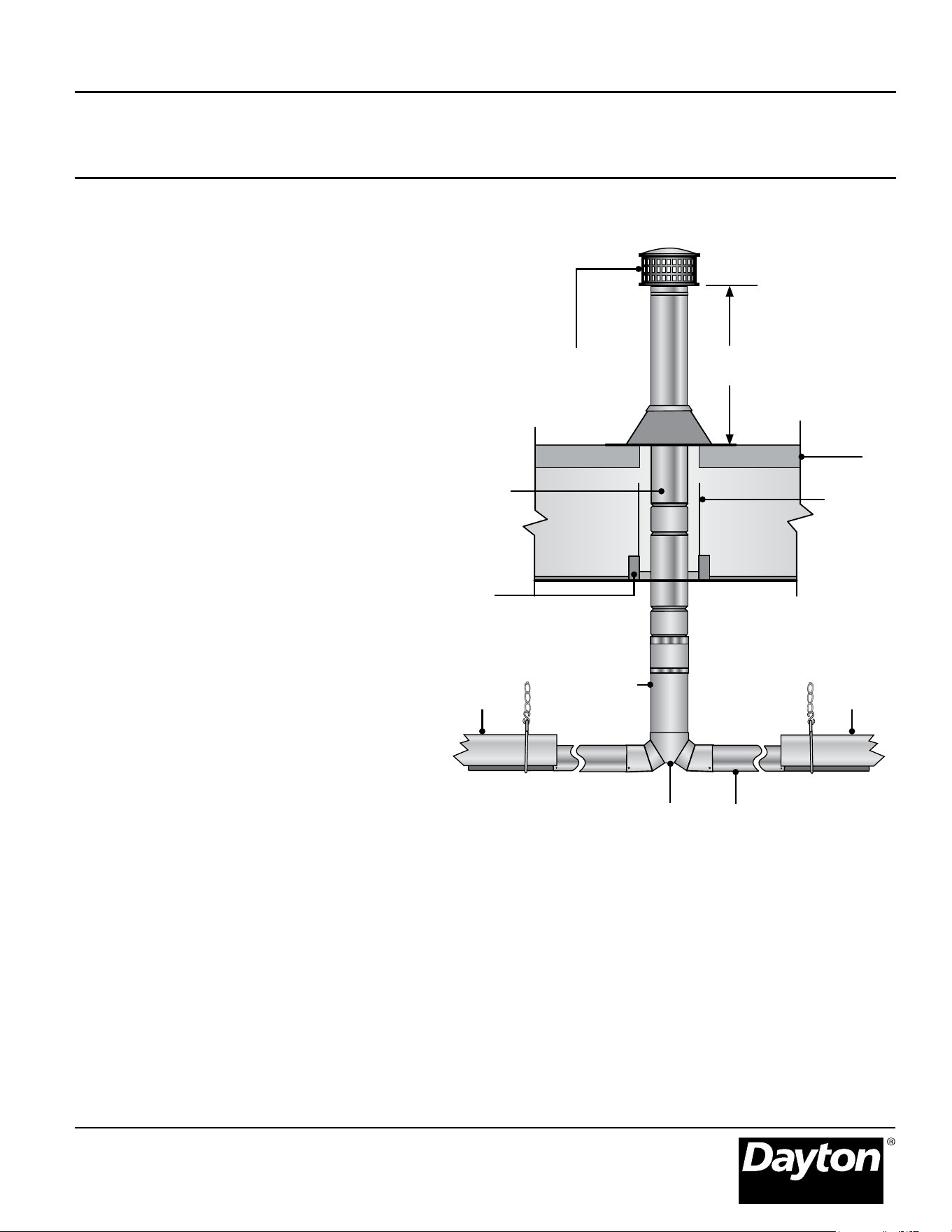
**Consult the NFPA ANSI Z223.1 Gas Vent Termination criteria if roof pitch exceeds 9:12.
Rooftop Vent Cap
Roof
Dual Exhaust Assembly
Heater
Firestop Spacer
Double-Wall B Vent
24 in.
Min.**
Heater
Single-Wall Vent Pipe
6” Single-Wall
Vent Pipe
Use Attic
Insulation
Shield
(Field Supplied)
Dayton Installation, Operation, Maintenance, and Parts Manual
Models 7D837A thru 7D849A, 7D851A, 7AR79 thru 7AR88
27
Common Venting (Category I)
Figure 2.24 • Common Rooftop Venting - Side View
• A staggered arrangement or a dual
exhaust assembly (P/N: Y) must be
used when joining two heaters to a
common vent so that by-products of
one heater do not ow into the
adjoining vent of the other heater.
• A Category III appliance may be
common vented only if the
appliances are on the same control
device so that they may only be
operated at the same time to prevent
the backow of exhaust gases into a
non-operational appliance. The
venting system must follow all
guidelines for Category III venting as
listed on page 26.
• 6” diameter double-wall type B-vent
and 6” vent cap (P/N: SWD-6) must
be used.
• The vent connector should be routed
in the most direct route from the
units to the common vent.
• Where two or more vent connectors
enter a common gas vent or chimney
ue, the smaller connector shall enter
at the highest level consistent with
the available head room or clearance
to combustible material.
• Restrictions within the common vent
such as elbows should be minimized.
Each elbow installed within the
common portion of the vent carrying
system reduces the maximum
common vent capacity by 10%. Refer
to NFPA 54 IFEC tables 13.2(a)
through 13.2(e) for capacity.
• The vent connector capacities allow
for the use of two 90° directional
changes. For each additional required
elbow, the vent connector capacity is
reduced by 10%.
• The common vent cross sectional area
must be equal to or greater than the
largest vent connector cross sectional
area.
Dayton Installation, Operation, Maintenance, and Parts Manual
Dayton Tube Heaters
®
7D837A thru 7D849A, 7D851A, 7AR79 thru 7AR88
28
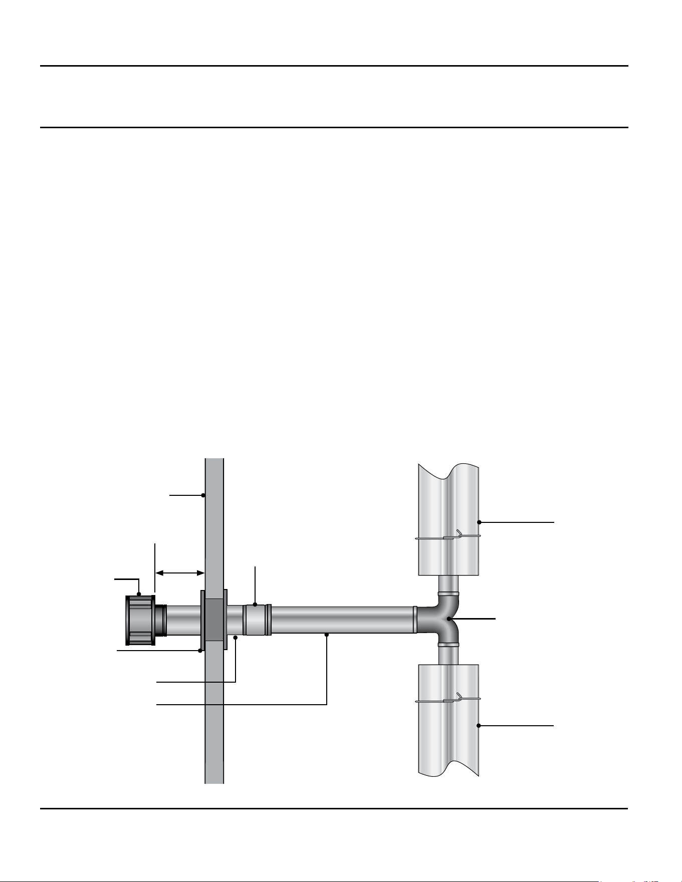
Common Venting (Category III)
Figure 2.25 • Common Sidewall Venting - Top View
Double-Wall B Vent
Heater
Heater
Dual Exhaust Assembly
Sidewall
Sidewall
Vent Cap
Wall Thimble
B to C
Adapter
6” Single Wall Vent
6 in.
Min.
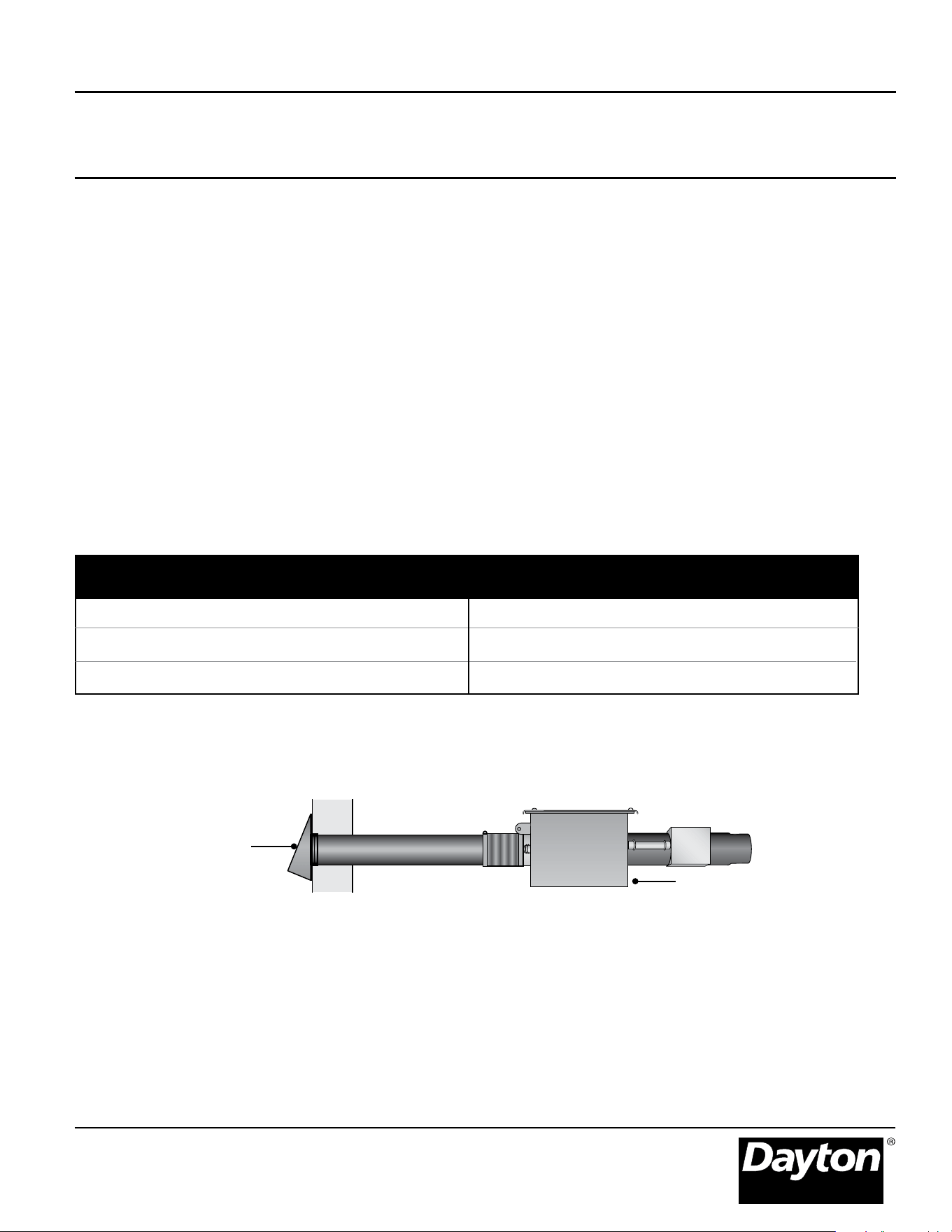
Optional Unvented Operation
When installing in an unvented
configuration:
• A factory vent cap/diffuser (P/N:
3F839) must be used.
• Where unvented heaters are used,
natural or mechanical means must be
provided to supply and exhaust a
minimum of 4 CFM/1,000 BTU/h
input of installed heaters.
NOTE: Gravity or mechanical means
may be used to accomplish the air
displacement. Local codes may
require that the mechanical exhaust
system be interlocked with the
electrical supply line to the heaters,
enabling both to function
simultaneously.
Figure 2.26 • Minimum End Clearance for Unvented Heater
31 cm
31 cm
12”
12”
• The minimum clearance between the
air intake and the exhaust terminal is
4 feet.
NOTE: When installing in a U-tube
conguration, use extra caution to
separate vent gases from heater
intake.
• Exhaust openings for removing the
ue products must be located above
the level of the heater(s).
Dayton Installation, Operation, Maintenance, and Parts Manual
Models 7D837A thru 7D849A, 7D851A, 7AR79 thru 7AR88
29
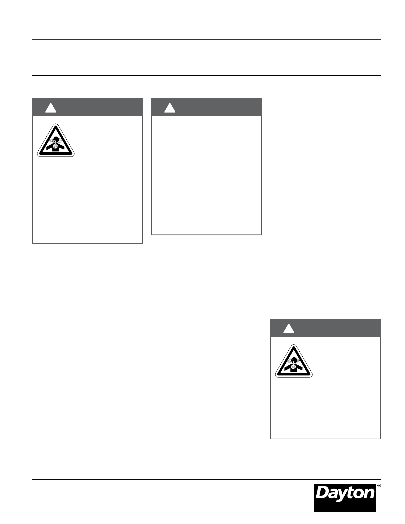
WARNING
!
!
Not for residential
use.
The use of unvented
tube heaters in
residential indoor
spaces may result in property damage,
serious injury, or death. Use unvented
operation in commercial and industrial
installations with proper ventilation
rates only.
Combustion Air Requirements
NOTICE
This heater has a factory preset air
orice for proper combustion air
supply. If using combustion air intake
from indoors, the required volume of
the space must be a minimum of
50 ft
3
/1000 BTU/h of installed heater
input unless the building is of unusually
tight construction. If the building has
air inltration rates of less than 0.40 air
changes per hour, outside combustion
air is typically needed unless the sheer
size of the building allows otherwise.
Non-contaminated air for
combustion must be ducted to the
heater if chlorinated or uorinated
contaminants, high humidity, and
other contaminants such as sawdust or
welding smoke are present in the area
where the heater is installed, or if the
building has a negative pressure.
Combustion air intake may be located
on either the sidewall or the roof.
Figures 2.27 - 2.29.
Dayton Installation, Operation, Maintenance, and Parts Manual
Dayton Tube Heaters
®
7D837A thru 7D849A, 7D851A, 7AR79 thru 7AR88
30
Roof Intake Cap
Roof
18” Min.
Burner
Control Box
Flexible Air Inlet Boot
4” pipe
Wall
Air Intake
Cap
Flexible Air Inlet Boot
4” pipe
Burner
Control Box
Roof
Flexible Air
Inlet Boot
Roof Intake Cap
18” Min.
6” pipe
4” pipe4” pipe
Burner
Control Box
Figure 2.27 • Vertical Outside Air Supply for Single Heater
Side View
Figure 2.28 • Horizontal Outside Air Supply for Single Heater
Side View
Figure 2.29
Vertical Outside Air Supply for Common Heater • Side View
Note: Common
intake heaters
must share the
same thermostat.
Dayton Installation, Operation, Maintenance, and Parts Manual
Models 7D837A thru 7D849A, 7D851A, 7AR79 thru 7AR88
31
Air Intake Cap
Burner Control Box
Guidelines:
4 in. 20 ft. 4 in.(single)/6 in.(dual) 20 ft.
5 in. 30 ft. 4 in.(single)/8 in.(dual) 30 ft
6 in. 40 ft.
Air Intake Duct Size Max. Intake Length Duct Size Max. Intake Length
Single Heater Intake Dual Heater Intake
Consult factory for longer intake lengths.
Limitations for length and size of combustion air intake duct
Combustion Air Requirements
General Requirements
• No more than two 90° elbows are
allowed.
• Allow for expansion. Use a 4” exible
hose to connect the duct to the
burner control box.
• Do not draw air from attic space.
• In humid environments, use insulated
duct, PVC pipe, or DWV (drain waste
vent) to prevent condensation on the
outer surface.
• Separate air intake duct from vent
pipe a minimum of 4’. Also, place
pipe higher than adjacent air intake
duct.
• A factory approved wall intake cap
(P/N: 3F837) must be used with
horizontal outside intake ducts. The
wall intake cap (P/N: 3F837) must be
installed to prevent blockage. Locate
the intake where dirt, steam, snow,
etc. will not contaminate or clog the
intake screen.
Figure 2.30 • Combustion Air Intake
Dayton Installation, Operation, Maintenance, and Parts Manual
Dayton Tube Heaters
®
7D837A thru 7D849A, 7D851A, 7AR79 thru 7AR88
32
WARNING
!
!
Improperly connected gas lines may
result in re, explosion, poisonous
fumes, toxic gases, asphyxiation, or
death. Connect gas lines in
accordance to national, state,
provincial, and local codes.
Gas Supply
IMPORTANT! Before connecting the
gas supply to the burner control box:
• Verify that the heater’s gas type (as
listed on the rating plate) match that
of your application.
• Check that the gas piping and
service has the capacity to handle
the total gas consumption of all
heaters being installed, as well as
any other gas appliances being
connected to the supply line.
• Check that the main gas supply line
is of proper diameter to supply the
required fuel pressures.
Note: Check manifold pressure at the tap on the gas valve. Readings will be above atmospheric pressure.
Pressure Equivalents: 1 Inch W.C. = .058 oz/sq. in. = 2.49 Mbar
Type of Gas
Required
Manifold Pressure
Minimum
Inlet Pressure
Maximum
Inlet Pressure
Natural 3.5 Inches W.C. 5.0 Inches W.C. 14.0 Inches W.C.
Propane 10.0 Inches W.C. 11.0 Inches W.C. 14.0 Inches W.C.
• If utilizing used pipe, verify that its
condition is clean and comparable to
a new pipe. Test all gas supply lines
in accordance with local codes.
• Test and conrm that inlet pressures
are correct. Refer to the rating
plate on the burner control box for
required minimum and maximum
pressures (see chart below). The gas
supply pipe must be of sufcient
size to provide the required capacity
and inlet pressure to the heater
(if necessary, consult the local gas
company). Do not exceed the
maximum allowed pressure for the
heater, the space or the gas piping
system.
Manifold Pressure
Gas Connection
This heater must be installed and
serviced by trained gas installation
and service personnel only.
Dayton Installation, Operation, Maintenance, and Parts Manual
Models 7D837A thru 7D849A, 7D851A, 7AR79 thru 7AR88
33
The installation must conform with local
building codes or, in the absence of
such codes, the National Fuel Code
(NFPA 54) and in conjunction with ANSI
Z21.24/CSA 6.10 “Connectors for Gas
Appliances”.
IMPORTANT! The heating system will
expand and contract during operation.
Allowances for expansion must be
made between the connection to the
heater and the gas supply. Excessive
bending, kinks, twists, or vibration must
be avoided. A exible gas connection of
approved type is required. Flexible
stainless steel gas connectors installed
in one plane, and without sharp bends,
kinks, or twists is recommended.
WARNING
!
!
Failure to install, operate,
or service this appliance
in the approved manner
may result in property
damage, injury, or death. Only trained,
qualied gas installation and service
personnel may install or service this
equipment.
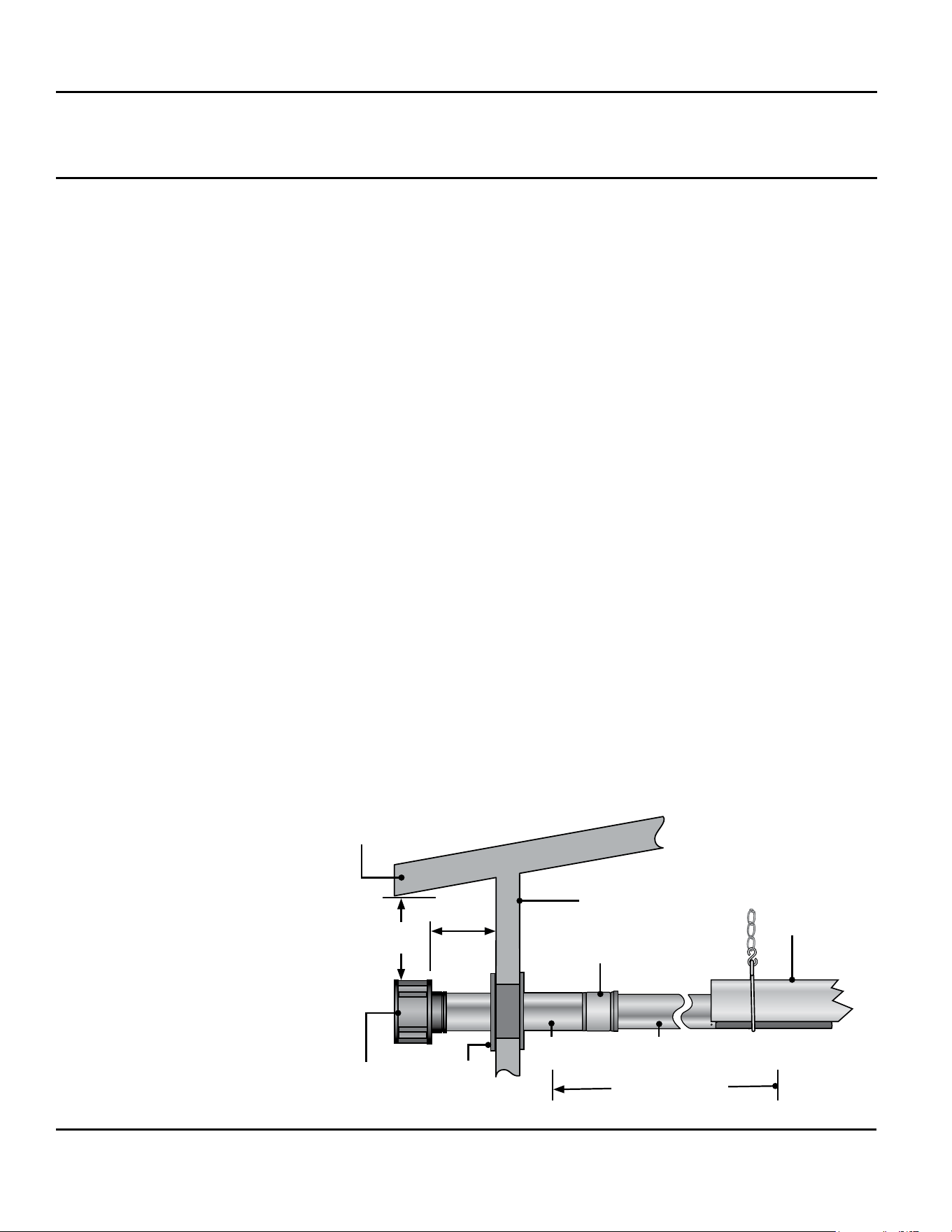
To connect the gas:
The gas pipe and connection must be
supported independently. Do not
install gas supply line in a manner that
bears the weight of the heater.
Connect the main gas supply line with
an approved exible connector (Figures
2.31 & 2.32) or, if national or local
codes require rigid piping, a swing
joint. See the safety messages at the
beginning of this section.
The gas outlet must be in the same
room as the appliance and accessible.
It may not be concealed within or run
through any wall, oor, or partition.
When installing the heater in a
corrosive environment (or near
corrosive substances), use a gas
connector suitable for the
environment. Do not use the gas
piping system to electrically ground the
heater.
1. Install a sediment trap / drip leg if
condensation may occur at any
point of the gas supply line. This will
decrease the possibly of loose scale
or dirt in the supply line entering the
heater’s control system and causing
a malfunction.
NOTE: High pressure gas above 14”
W.C. (water column pressure) requires
a high pressure regulator and ball
valve.
2. Form the stainless steel exible
connector into a smooth C-shape
allowing 12 in. between the exible
connector’s end nuts. Figure 2.31.
3. Attach the ball valve to the gas
supply pipe. Apply pipe compound
to NPT adapter threads to seal the
joint. Use only a pipe compound
resistant to the actions.
NOTE: Provide a 1/8 in. NPT plugged
tapping accessible for test gauge
connection immediately upstream of
gas connection to the heater (provided
on ball valve).
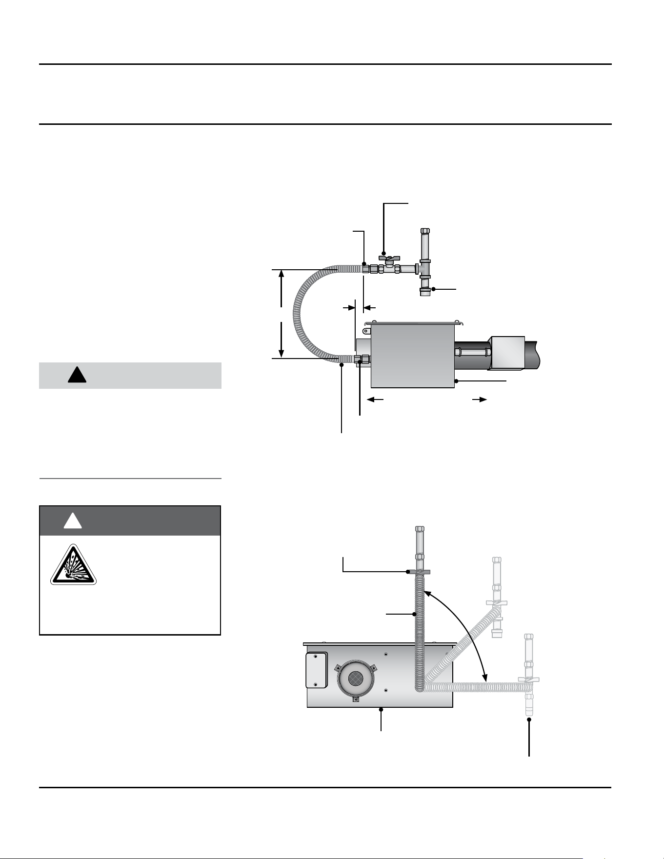
12”
Stainless Steel Gas Connector, formed
into smooth C-Shape
Adapter
2” max displacement
Drip Leg/
Sediment Trap
Heater Movement
Adapter
Burner
Control Box
Ball Valve / Inlet Tap
Ball Valve/Inlet Tap
Remove cap to clean
sediment trap
Horizontal
Burner Control Box
Stainless Steel
Gas Connector
Dayton Installation, Operation, Maintenance, and Parts Manual
Dayton Tube Heaters
®
7D837A thru 7D849A, 7D851A, 7AR79 thru 7AR88
34
WARNING
!
!
Testing for gas leaks
with an open ame or
other sources of
ignition may lead to a
re or explosion and cause serious
injury or death. Test in accordance
with NFPA or local codes.
4. Attach the exible connector to the
adapter and burner control box
inlet. Seal the joints.
NOTE: Excessive torque on the manifold
may misalign the orice. Always use
two wrenches to tighten mating pipe
connections.
5. Final assembly must be tested for
gas leaks according to NFPA or
local codes.
Figure 2.32 • Flexible Gas Connection End View
Figure 2.31 • Flexible Gas Connection Side View
Gas Supply
CAUTION
!
When using a stainless steel exible
connector, do not attach the connector
nuts directly to the gas pipe supply.
Connector nuts must be installed to an
approved adapter.
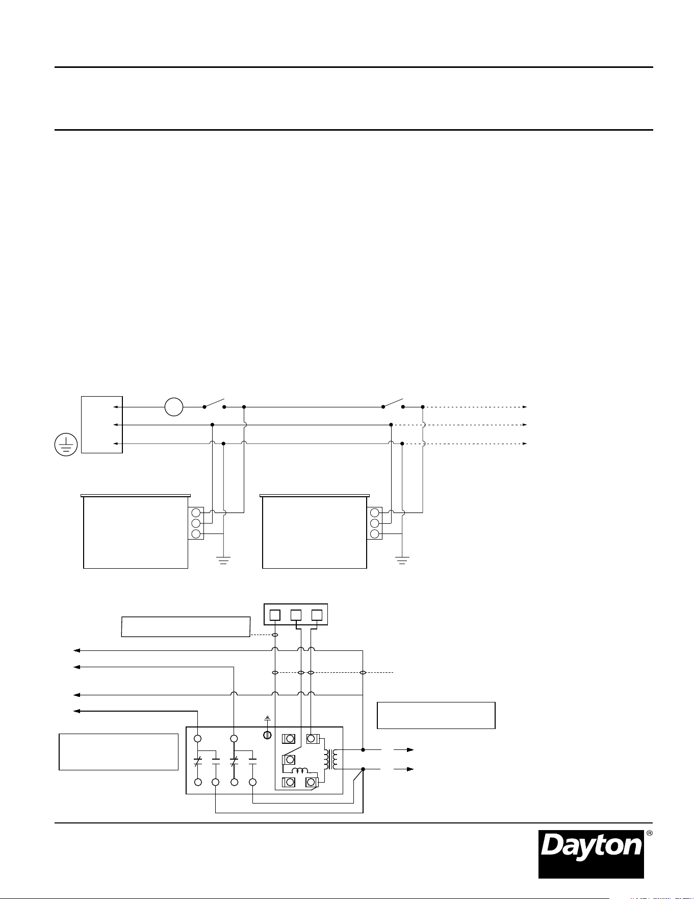
120V-60 Hz.
Supply
NOTE: Up to 4 line voltage tube heaters can be
wired to most thermostats.
T
L1
Neutral
Ground
Heaters on the same vent must
share the same thermostat.
Additional heaters
Multiple Burner Box
(if applicable)
Burner Box
Dayton Installation, Operation, Maintenance, and Parts Manual
Models 7D837A thru 7D849A, 7D851A, 7AR79 thru 7AR88
35
Electrical Requirements
• Verify that the heater’s voltage (as
listed on the rating plate) matches
that of your application.
• Heaters operate on 120 volts,
60Hz., single phase. The maximum
amperage requirement is 4.8 amps
starting current; 1.1 amps running
current per heater.
• Observe proper electrical polarity.
Figure 2.33 - Field Wiring 120V Connection(s)
• The heater must be grounded
in accordance with the National
Electrical Code ANSI/NFPA70 (latest
edition).
• It is recommended that the
thermostat be installed on the hot
side of a fused supply line and have
sufcient amp rating for the heater(s)
that it controls.
• Clearances to combustibles must
be maintained between electrical
apparatus and wiring. See clearance
data on page 7.
• Wiring must not be run above or
below the heater or exposed to the
radiant output.
• Installations utilizing a 24 volt
thermostat require a relay
transformer. Figure 2.34.
Figure 2.34 - General Thermostat Wiring Diagram with Combination Relay Transformer
G W R
24V 24V
Common required for thermostats
that require constant power.
TO HEATER BRANCH #1
TO HEATER BRANCH #2
115V
115V
WHITE
WHITE
VIOLET
BLACK
RED
RED/YELLOW
COIL
W
W
B
G
Y C
R
L2
L1
115V
POLE
#2
POLE
#1
BY OTHERS
NOTE: This Transformer Relay
will handle up to 3 tube heaters
per branch (6 tube heaters total)
NOTE: Brown and Yellow wires
are normally not used.
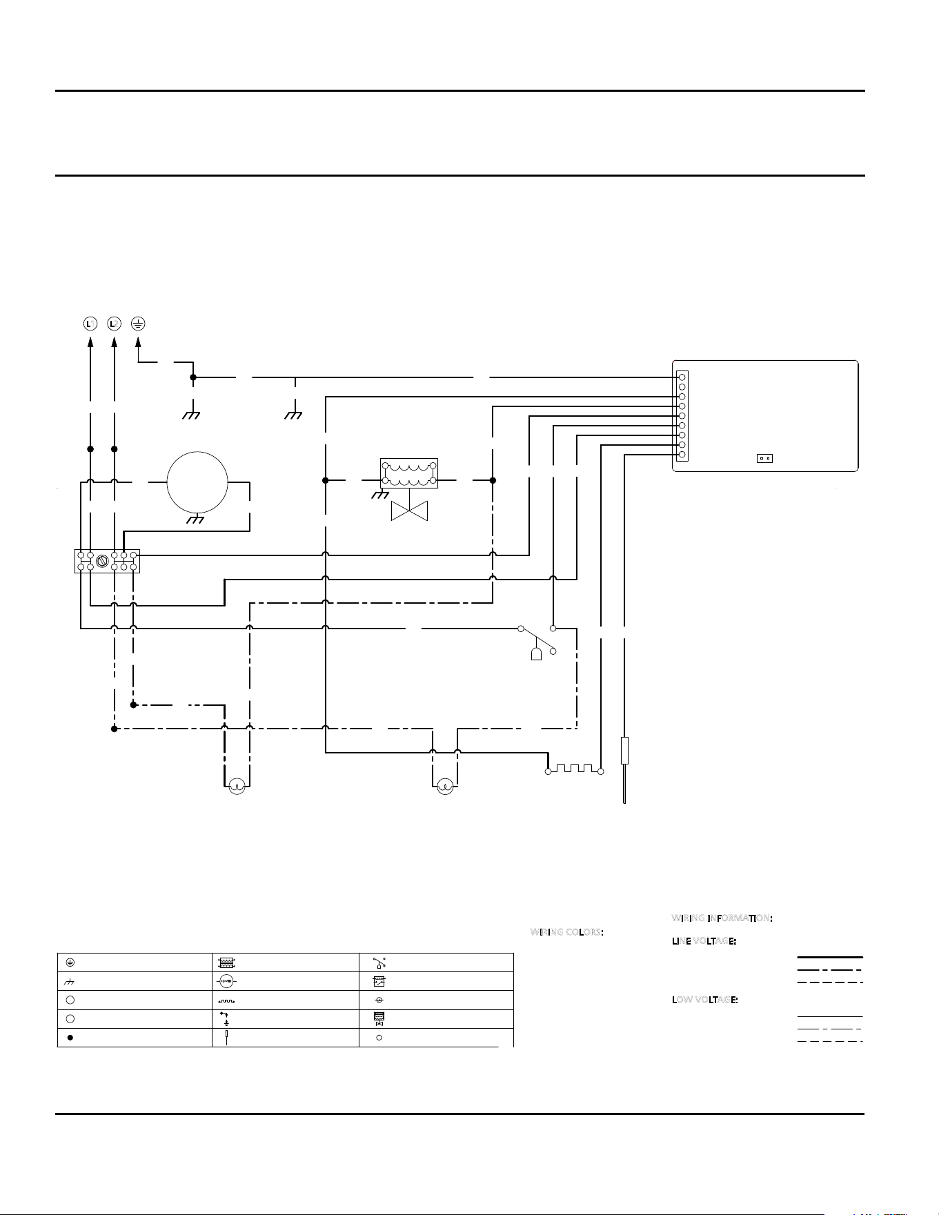
Dayton Installation, Operation, Maintenance, and Parts Manual
Dayton Tube Heaters
®
7D837A thru 7D849A, 7D851A, 7AR79 thru 7AR88
36
Internal Wiring Diagram
If any of the original wire as supplied with this appliance must be replaced, it must be replaced with wiring material having
a rating of at least 600 V, 105°C.
L2
L1
BLOWER
EARTH GROUND
CHASSIS GROUND
LINE VOLTAGE
NEUTRAL
WIRE NUT
TRANSFORMER
BLOWER MOTOR
HOT SURFACE IGNITER
SPARK IGNITER
INDICATOR LIGHT
GAS VALVE
FLAME SENSOR
PRESSURE SWITCH
S.P.S.T. RELAY
FACTORY STANDARD
FACTORY OPTION
FIELD INSTALLED
FACTORY STANDARD
FACTORY OPTION
FIELD INSTALLED
QUICK-CONNECT TERM.
BK....................BLACK
R.......................RED
Y.......................YELLOW
BL......................BLUE
W......................WHITE
BN....................BROWN
O......................ORANGE
G.......................GREEN
PR.....................PURPLE
GY.....................GRAY
PK......................PINK
G
BK
O
W
BRBK
G
G
G
W
BK
BK
W
BK
BK
W BK
W
R
W
BKBK
BK
BK
BK
G
BK
BK
VALVE
INDICATOR
LIGHT
P.S.
INDICATOR
LIGHT
COMPONENT CODES
WIRING COLORS:
LINE VOLTAGE:
LOW VOLTAGE:
WIRING INFORMATION:
L2L1
IGNITER
FLAME
SENSOR
PRESSURE
SWITCH
GAS VALVE
BLOWER
IGNITION
MODULE
F.C. TEST PINS
GROUND
NETURAL
VALVE
L2 (NEUTRAL)
THERMOSTAT
L1
SIC1
PROBE
Dayton Installation, Operation, Maintenance, and Parts Manual
Models 7D837A thru 7D849A, 7D851A, 7AR79 thru 7AR88
37
WARNING
!
!
LIGHTING PROCEDURES:
1. Verify that service lid is secured.
2. Open (turn on) gas supply to the
heater.
3. Close (turn on) electrical circuit
(typically thermostat).
4. If the heater fails to light, turn off
gas, open electrical circuit (set
thermostat to lowest setting or to
off). Wait ve (5) minutes before
repeating above steps.
SHUTDOWN PROCEDURES:
1. Open (turn off) electrical circuit.
2. Close (turn off) gas supply to the
heater.
3. Wait ve (5) minutes before
relighting heater.
This heater is not
equipped with a pilot
ignition system.
Do not attempt to light the system
manually.
OPERATION
Starting Circuit
Upon a call for heat, the fan is
energized. Once operational static
pressure is achieved, the differential
switch will close initiating the ignition
sequence. After a 5-second delay, the
hot surface igniter is energized for 45
seconds and the control allows the gas
valve to open.
The trial for ignition is 8 seconds. If
ame sense is not established within
8.5 seconds, the heater will attempt
two (2) additional ignition sequences
before proceeding to soft lockout. Soft
lockout automatically retries after one
(1) hour or the control can be reset by
briey interrupting the power source.
Sequence of Operation
Running Circuit
After ignition, the ame rod monitors
the burner ame. If sense of ame is
lost, the control immediately acts to
reignite the gas-air mixture (identical to
the starting sequence). If ame sense is
not established within 8.5 seconds, the
heater will attempt two (2) additional
ignition sequences before proceeding
to soft lockout. The control can be
reset by briey interrupting the power
source.
Dayton Installation, Operation, Maintenance, and Parts Manual
Dayton Tube Heaters
®
7D837A thru 7D849A, 7D851A, 7AR79 thru 7AR88
38
Routine Inspection
WARNING
!
!
Personal injury or death may result if
maintenance is not performed by
properly trained gas installer or
service personnel. Contact the
installing distributor or place of
purchase for service. Do not operate
heating system if repairs are
necessary.
WARNING
!
!
At least once per year, the heating
system should be inspected and
serviced by trained gas installation and
service personnel only. This inspection
should be performed at the beginning
of the heating season to ensure that all
heater components are in proper
working order and that the heating
system operates at peak performance.
Particular attention should be paid to
the following items.
• Blower Motor: Annual oiling of the
blower motor with SAE 20 oil will
extend bearing life signicantly.
Ensure that the squirrel cage in the
blower is kept clean. If dirt
becomes a problem, installation of
outside air intake ducts for
combustion is recommended.
• Vent pipe system: Check the
outside termination and the
connections at the heater. Inspect
the vent exhausts for leakage,
damage, fatigue, corrosion, and
obstructions. If dirt becomes a
problem, installation of outside air
intake ducts for combustion is
recommended.
• Combustion air intake system
(when applicable): Check for
blockage and/or leakage. Check
the outside termination and the
connection at the heater.
• Heat exchangers: Check the
integrity of the heat exchangers.
Replace if there are signs of
structural failure. Check for
corrosion and/or buildup within the
tube exchanger passageways.
• Burner: Check for proper ignition,
burner ame, and ame sense.
Flame should extend directly
outward from burner without
oating or lifting.
• Wiring: Check electrical
connections for tightness and/or
corrosion. Check wires for
damage.
• Gas Connection: Inspect the
integrity of the gas connection to
the heater. Check for leaks,
damage, fatigue, or corrosion. Do
not operate if repairs are necessary
and turn off gas supply to the
heater. Contact service personnel.
• Reectors: To maintain effective
infra-red heating, always keep both
sides of the reector clean.
Maintenance can vary signicantly
depending on the environment.
Dirt and dust can be vacuumed or
wiped with a soap and water
solution. Use metal polish if the
reectors are severely dirty.
Contact service personnel if repairs are
necessary. Do not operate unit.
WARNING
!
!
WARNING
!
!
Allow heater to cool
prior to servicing.
Disconnect power
to heater before
servicing.
Use protective
glasses when
cleaning the heater.
MAINTENANCE
Dayton Installation, Operation, Maintenance, and Parts Manual
Models 7D837A thru 7D849A, 7D851A, 7AR79 thru 7AR88
39
Symptom Possible Cause Corrective Action
Thermostat closed, fan doesn’t operate. • Blown fuse.
• Faulty thermostat.
• Loose or disconnected wire.
• Faulty fan.
• Replace.
• Replace.
• Repair as required.
• Lubricate, repair or replace.
Thermostat closed. Fan operates. Switch
does not close.
Note: If hot surface igniter is
energized, the indicator light is faulty.
• Loose or disconnected wire.
• Box lid or gasket not in place.
• Plugged pressure switch lines.
• Plugged or restricted exhaust vent.
• Bafe location incorrect.
• Faulty pressure switches.
• Repair as required.
• Put in place.
• Clean as necessary.
• Remove foreign matter.
• Re-position bafes at vent end.
• Replace only. Do not adjust.
Thermostat closed. Fan operates. Pressure
switch closes. No hot su
rface
igniter.
• Faulty hot surface igniter.
• Faulty circuit board.
• Replace.
• Replace.
Thermostat closed. Fan operates.
Pressure switch closes. Hot surface
igniter energizes. Valve does not open.
• Disconnect gas valve wires.
• Faulty circuit board.
• Faulty gas valve.
• Repair as required.
• Replace.
• Replace.
Thermostat closed. Fan and hot surface
igniter operate. Ignition occurs, burner
cycles off in less than 60 seconds.
• Low gas pressure.
• Bafe improperly positioned.
• Faulty exhaust pressure switch.
• Restricted ue vent.
• No electrical ground.
• Reversed polarity.
• Provide required gas pressure.
• Re-position bafe at vent end.
• Replace.
• Remove foreign matter.
• Connect electrical ground to junction box.
• Repair.
Thermostat closed. Fan and hot surface
igniter operate. After 45 seconds hot
surface igniter shuts off. No ignition.
• Closed gas supply.
• Dirty or restricted orice.
• Faulty valve. Disconnected wire.
• Inlet pressure exceeds 14 Inches W.C.
• Open all gas connections.
• Remove. Clean with a soft object.
• Replace or repair.
• Lower inlet pressure.
Loss of heater efciency. • Low gas pressure.
• Dirty or restricted orice.
• Foreign matter inside burner.
• Unit cycles on and off.
• Reector is dirty or not in place.
• Clogged fan blower.
• Provide required gas pressure.
• Remove. Clean with a soft object.
• Clean as necessary.
• Check previous symptom.
•
Clean with aluminum cleaner and soft cloth.
• Clean.
Radiant tube leaking burnt gases. • Loose tube connections.
• Holes or cracks in radiant tubes.
• Ensure that tubes are fully connected
and clamped properly.
• Replace.
Condensation. • Stack length is too long.
• Light gauge ue stack used.
• Contaminated combustion air.
• Shorten stack length.
• Minimum of 26 ga. vent pipe required.
• Provide fresh air inlet duct.
Tube bowing. • Insufcient combustion air.
• Over red.
• Contaminated combustion air.
• Heater unable to expand properly.
•
Provide 1 sq. in. of free air for every 5,000 BTU/h of input.
• Check gas pressure and orice size.
• Provide fresh air inlet duct.
• Remount with exible inlet or vent pipe.
Tube corroding. • Contaminated combustion air. • Provide fresh air inlet duct.
Visual inspection of burner operation
not possible.
• Dirty or sooted sight glass.
• Unit mounted upside-down.
• Remove, clean or replace.
• Mount correctly.
Stack sooting. • Insufcient combustion air.
• Improper gas.
• Dirty fan or blockage.
• Provide 1 sq. in. of free air for every
5,000 BTU/h of input.
• Correct with proper gas input (or clean).
Odor or fumes in space
(normal during rst ring and
will subside after initial burn off,
approximately 20 minutes).
• Vaporized solvents decomposing when
contacting radiant tubes.
• Evaporation of oils, solvents at oor level.
• Fork lifts.
• Loose tube / vent connections.
• Provide proper ventilation.
• Provide proper ventilation.
• Tighten tube clamps to 50-100 ft-lb.
• Seal vent pipes.
Troubleshooting Guide
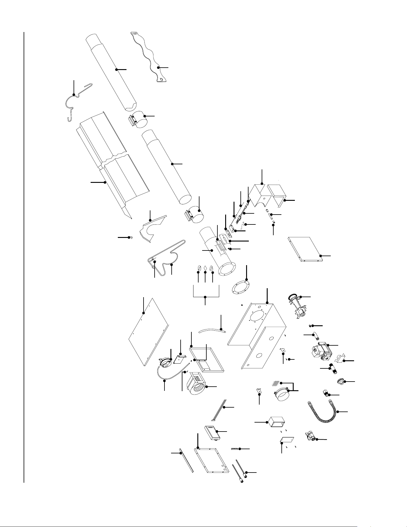
Dayton Installation, Operation, Maintenance, and Parts Manual
7D837A thru 7D849A, 7D851A, 7AR79 thru 7AR88
For Repair Parts, call 1-800-323-0620
24 hours a day - 365 days a year
Please provide following information:
-Model number
-Serial number (if any)
-Part description and number as shown in parts list
Repair Parts Illustration for Dayton Tube Heater
65
66
62
1
36, 37
18
52, 53
35
22
51
39
42
27
17
24
59
63
20
47
54, 55, 56, 57
41
46
23
17
43
25
68
58
2
60
6
5
4
38
9
8
10
11
12
34
31
14
15, 16
14,
70
15,32
21
13, 33
26
61
48
49
50
19
40
67
45
44
3
28
7
64
69
29
30
40

41
• Conversions from natural gas to LP gas require the use of one TP-241 and one TP-204-Size and TP-114-Size.
• Conversions from LP gas to Natural gas require the use of one TP-240 and one TP-204-Size and TP-114-Size.
• Conversions between different BTU’s sizes are not allowed.
Dayton Installation, Operation, Maintenance, and Parts Manual
Repair Parts List for Dayton Tube Heater
7D837A thru 7D849A, 7D851A, 7AR79 thru 7AR88
Ref.
No.
Description Part No. Quantity Ref.
No.
Description Part No. Quantity
1 Control Box Cover TP-1 1 36 Burner (50-100 MBH models) TP-3072 1
2 Flange Gasket TP-5 1 37 Burner (125-200 MBH models) TP-201B 1
3 Conduit Coupling TP-9 1 38 16” Burner Tube w/ Flange (ttings included) TP-380 1
4 Conduit 4” x 1/2” TP-10 1 39 Gas Orice - Consult Factory TP-204 1
5 Hot Surface Igniter Box TP-11 1 40 Hot Surface Igniter Holder TP-205 1
6 Hot Surface Igniter Box Cover TP-12 1 41 Pressure Switch Mounting Bracket TP-207 1
7 8 x 1/2” Self-drilling Screw TP-13 4 42 Gas Valve Mounting Bracket TP-208B 1
8 Sight Glass Gasket TP-14 1 43 1/2” x 3” Pipe Nipple TP-212 1
9 Sight Glass TP-15 1 44 Hot Surface igniter Wiring Harness TP-214 1
10 Sight Glass Washer TP-16 1 45 Pressure Switch Barb TP-217 1
11 Sight Glass Kit TP-17 1 46 Vinyl Pressure Sensing Tube (exhaust) TP-218 1
12 4” Wire Hanger with Tension Spring TP-19B 3-7 47 Vinyl Pressure Sensing Tube (burner) TP-219 1
13 120” Aluminum Reector TP-20C 2-6 48 Hot Surface Igniter Holder Gasket TP-221 1
14 4” Standard Tube Clamp TP-21B 2-6 49 Flame Rod TP-222 1
15 120” ALUM Combustion/Radiant Tube TP-26A 2-5 50 Flame Rod Wire TP-222A 1
16
120” AL-TI Combustion Tube (150-200MBH Models)
TP-26B 1 51 Gas Manifold TP-223 1
17 Control Box Mounting Bracket TP-31B 2 52 Gas Valve Assembly - Natural Gas TP-240 1
18 1/2” Shut-off Ball Valve/ Inlet Tap TP-33B 1 53 Gas Valve Assembly - Propane Gas TP-241 1
19 Silcone Carbide Hot Surface Igniter TP-50A 1 54 Differential Pressure Switch (50-100 MBH) TP-264B 1
20 Fan Blower TP-55A 1 55 Differential Pressure Switch (125-150 MBH) TP-264E 1
21 36” Interlocking Heat Bafe TP-65I 2-5 56 Differential Pressure Switch (175 MBH) TP-264D 1
22 2” x 4” Outlet Box TP-66 1 57 Differential Pressure Switch (200 MBH) TP-264F 1
23 2” x 4” Outlet Box Cover TP-67 1 58 Divider Panel w/ Pressure Switch Mtg. Tabs TP-301 1
24 Control Box Gasket (per foot) TP-70 6 59 Left End Panel with Light Holes TP-302 1
25 Rubber Grommet TP-76 1 60 Right End Panel TP-303 1
26 Reector Center Support TP-82 2-6 61 Ignition Plate Gasket TP-321 1
27 Stainless Steel Flexible Gas Connector TP-83 1 62 120V Amber Operational Indicator Light TP-328 2
28 1/2” Female/Male Flare Fitting TP-84 1 63 1/4” Terminal Block TP-329 1
29 1/4” x 1/4” Brass Atmos. Barb Fitting TP-97 1 64 Green Self-tap Screw TP-331 1
30 Aluminum Reector End Cap TP-105 2
65
Potted Circuit Board TP-351A 1
31 Reector End Cap Clip (pkg. of 8) TP-106 1
66
Circuit Board Wiring Harness TP-352A 1
32 60” ALUM Radiant Tube TP-111 1
67
Hot Surface Igniter Plate TP-383A 1
33 60” Aluminum Reector TP-112 1
68
Burner Control Box Outer Shell TP-804 1
34 Reector Tension Spring TP-113 1
69
Globar Holder Spring Clip TP-206 1
35 Plastic Air Orice w/ Screen - Consult Factory TP-114 1
70
Stainless Steel Tube Clamp (150-200MBH Models)
TP-220 1
Dayton Installation, Operation, Maintenance, and Parts Manual
Dayton Tube Heaters
®
7D837A thru 7D849A, 7D851A, 7AR79 thru 7AR88
42
Date Maintenance Performed
Replacement Parts Required
Maintenance Log

Dayton Installation, Operation, Maintenance, and Parts Manual
Models 7D837A thru 7D849A, 7D851A, 7AR79 thru 7AR88
43
Notes

Dayton Installation, Operation, Maintenance, and Parts Manual
Dayton Tube Heaters
®
7D837A thru 7D849A, 7D851A, 7AR79 thru 7AR88
44
Dayton One-Year Limited Warranty. Dayton Radiant Tube Heaters, Models 7D837A thru 7D849A, 7D851A, 7AR79 thru 7AR88
covered in this manual, are warranted by Dayton Electric Mfg. Co. (Dayton) to the original user against defects in workmanship
or materials under normal use for one year after date of purchase. Any part which is determined to be defective in material or
workmanship and returned to an authorized service location, as Dayton designates, shipping costs prepaid, will be, as the exclusive
remedy, repaired or replaced at Dayton’s option. For limited warranty claim procedures, see PROMPT DISPOSITION below. This limited
warranty gives purchasers specic legal rights which vary from jurisdiction to jurisdiction.
Additional Limited Warranty. In addition to the above mentioned one-year warranty, Dayton warrants the original purchaser an
additional 4-year extension on the combustion chamber, radiant tubes and stainless steel burner. This 4-year extension excludes
electrical/purchased components.
General Conditions. Dayton will not be responsible for labor charges for the analysis of a defective condition of the heater or for
the installation of replacement parts. The warranties provided herein will not apply if the input of the heater exceeds the rated input
at time of manufacturing or if the heater in the judgement of the Company has been subjected to misuse, excessive dust, improper
conversion, negligence, accident, corrosive atmospheres, excessive thermal shock, excessive vibration, physical damage to the
heater, alterations by unauthorized service personnel, operation contrary to Dayton’s instructions or if the serial number has been
altered, defaced or removed. Dayton shall not be liable for any default or delay in the performance of these warranties caused by
contingency beyond its control, including war, government restriction or restraints, strikes, re, ood, short or reduced supply of raw
materials, or parts. The warranties herein shall be null and void if the heater is not installed by a competent heating contractor and/
or if the heater is not installed according to Dayton’s instructions, normal industry practices and/or if the heater is not maintained
and repaired according to Dayton’s instructions. Normal product degradation and wear (rust, oxidation, etc.) does not constitute a
material defect and applicable warranty claim.
Limitation of Liability. To the extent allowable under applicable law, Dayton’s liability for consequential and incidental damages is
expressly disclaimed. Dayton’s liability in all events is limited to and shall not exceed the purchase price paid.
Warranty Disclaimer. Dayton has made a diligent effort to provide product information and illustrate the products in this literature
accurately; however, such information and illustrations are for the sole purpose of identication, and do not express or imply a
warranty that the products are merchantable, or t for a particular purpose, or that the products will necessarily conform to the
illustrations or descriptions. Except as provided below, no warranty or afrmation of fact, expressed or implied, other than as stated
in the “LIMITED WARRANTY” above is made or authorized by Dayton.
Product Suitability. Many jurisdictions have codes and regulations governing sales, construction, installation, and/or use of products
for certain purposes, which may vary from those in neighboring areas. While Dayton attempts to assure that its products comply
with as many codes, it cannot guarantee compliance, and cannot be responsible for how the product is installed or used. Before
purchase and use of a product, review the product applications, and all applicable national and local codes and regulations, and be
sure that the product, installation, and use will comply with them.
Certain aspects of disclaimers are not applicable to consumer products: e.g., (a) some jurisdictions do not allow the exclusion
or limitation of incidental or consequential damages, so the above limitation or exclusion may not apply to you: (b) also, some
jurisdictions do not allow a limitation on how long an implied warranty lasts, consequently the above limitation may not apply to you:
and (c) by law, during the period of this limited warranty, any implied warranties of implied merchantability or tness for a particular
purpose applicable to consumer products purchased by consumers, may not be excluded or otherwise disclaimed.
Prompt Disposition. Dayton will make a good faith effort for prompt correction or other adjustment with respect to any product
which proves to be defective within limited warranty. For any product believed to be defective within limited warranty, rst write or
call dealer from whom the product was purchased. Dealer will give additional directions. If unable to resolve satisfactorily, write to
Dayton at address below, giving dealer’s name, address, date and number of dealer’s invoice, and describe the nature of the defect.
Title and risk of loss pass to buyer on delivery to common carrier. If product was damaged in transit to you, le claim with carrier.
LIMITED WARRANTY
Manufactured for Dayton Electric Mfg. Co.
Lake Forest, IL 60045 U.S.A.
